

Page 1

VICTOR Jr. CNC CYLINDER HEADS
®
For Chrysler 426-572 HEMI
Catalog #61169, 61175, 61179, 61189
INSTALLATION INSTRUCTIONS
PLEASE study these instructions carefully before beginning this installation. Most installations can be accomplished with common tools and
procedures. However, you should be familiar with and comfortable working on your vehicle. If you do not feel comfortable performing this
installation, it is recommended to have the installation completed by a qualified mechanic. If you have any questions, please call our Technical
Hotline at: 1-800-416-8628, 7:00 am - 5:00 pm, Pacific Standard Time, Monday through Friday.
IMPORTANT NOTE: Proper installation is the responsibility of the installer. Improper installation
will void your warranty and may result in poor performance and engine or vehicle damage.
DESCRIPTION: These Victor Jr. cylinder heads are designed for high
output 650+ hp Chrysler 426-572 engines. They feature fully CNC’d
combustion chambers and CNC blended seats for optimal air flow
performance. These cylinder heads also feature a revised exhaust
valve angle to accommodate larger intake valves. They also feature
brass tubes installed in exhaust pushrod holes to allow maximum
clearance with minimal port intrusion.
NOTE: Complete cylinder heads, #61175 and #61179, are
assembled and prepared for installation right out of the box. Bare
cylinder heads w/ valves, #61189, are shipped with reamed and
machined valve stem guides, as well as a valve job to match the
included intake and exhaust valves. Customer must supply their
own valve springs, retainers, valve stem seals and valve locks.
Bare heads, 61169, are shipped with reamed and semi-finished
valve stem guides and seats. Bare heads will require final sizing
and a valve job to match the specific valves being used.
IMPORTANT NOTES: READ BEFORE BEGINNING INSTALLATION!
For a successful installation, the Edelbrock Victor Jr. Cylinder Heads
require some components other than original equipment parts. To
complete your installation, you will need the following items:
q Head Gaskets (Min. Bore 4.375”): Edelbrock #7347 or Fel-Pro
#1104
q Intake Manifold Gaskets: Fel-Pro #1234
q Exhaust Gaskets: Fel-Pro #1462
q Edelbrock Head Bolt Kit: Edelbrock #8513 or ARP 145-3901
CHECKING PISTON-TO-VALVE, VALVE-TO-BORE AND PISTON-TOHEAD CLEARANCES: Prior to installation, it is highly recommended
that valve-to-piston clearances are checked and corrected to minimum
specs, if necessary. These cylinder heads have larger-than-stock
valve sizes and will not work with the valve pockets in stock pistons,
especially if a high lift cam is used. The use of aftermarket pistons
and/or custom machining to your pistons is required. Actual valve-topiston clearance should be specified by your camshaft manufacturer.
Valve-to-bore clearance should also be checked, and the top of the
bore notched for clearance, if necessary (Min Clearance 0.030”).
ACCESSORIES: Although Edelbrock Cylinder Heads will accept
OEM components (valve covers, intake manifold, etc.), we highly
recommend that premium quality hardware be used with your new
heads. Continue to next column for hardware recommendations.
Head Bolts or Studs: High quality head studs or head bolts with
hardened washers must be used to prevent galling of the aluminum
bolt bosses. Edelbrock head bolt kit, #8513, includes all bolts which
must be used with these cylinder heads.
Rocker Arms and Valve Train: These heads are designed to use
stock offset rocker arm and valve train components.
CAUTION: Before installing rocker shafts, check for burrs or
other obstructions on the machined saddles where the shaft sits.
Remove any burrs and clean saddles thoroughly, if necessary.
Valve Covers: Edelbrock Victor Jr. CNC Chrysler cylinder heads
will accept factory style, Gen 2, HEMI valve covers and valve cover
gaskets.
Intake Manifold: Although the stock intake manifolds will fit,
the Victor Jr. heads should be matched with an appropriate high
performance manifold. Follow the manifold or gasket manufacturer’s
recommendations for installation.
Exhaust Headers: Although the stock exhaust manifolds/headers
will fit these Victor Jr. cylinder heads, it is highly recommended
to match these heads with appropriate high performance exhaust
headers. Follow the header manufacturer’s recommendations for
installation procedures.
Spark Plugs: Use 14mm x 3/4” reach gasketed spark plugs. Heat
range will vary by application.
NOTE: Use anti-seize on the plug threads to prevent galling in
the cylinder head, and torque to 10 ft./lbs. Do not overtighten
sparkplugs! If short reach plug is used, poor performance and
possible engine damage may occur.
Spark Plug Tube O-rings Edelbrock has included lower spark plug
tube O-rings with PN 61175 & 61179 cylinder heads. The purpose
of these O-rings is to help seal the spark plug tube from leaking oil
into the cylinder when checking or changing spark plugs. It is still
expected that a small amount of oil can enter the chamber even with
the lower O-ring installed, but the volume will be greatly reduced.
These O-rings get installed into the head in the machined groove down
by the spark plug threads. The O-rings must be lightly oiled prior to
test fitting the spark plug tube with the valve cover off of the head.
The tube should push into the lower O-ring with light force. If a lot of
force is required to push/twist the tube through the lower O-ring there
Catalog #61169, 61175, 61179, 61189
Rev. 11/13/14 - QT
Page 1 of 2
©2014 Edelbrock LLC
Brochure #63-61169
Page 2
is an issue. Stop the process, assess the problem and try again. If
spark plug tubes install successfully, remove the tubes and install the
valve cover. Following valve cover installation, insert the spark plug
tube using the OE O-ring for the spark plug tube seal at the valve cover
interface (not included with heads).
NOTE: The use of these lower spark plug tube O-rings is not
required. Simply remove and discard if not using.
INSTALLATION: Installation is the same as for original equipment
cylinder heads. Consult service manual for specific procedures, if
necessary. Be sure that the surface of the block and the surface of the
head are thoroughly cleaned to remove any oily film before installation.
Use alcohol or lacquer thinner on a lint-free rag to clean. Apply oil or
suitable thread lubricant to head bolt threads and the underside of
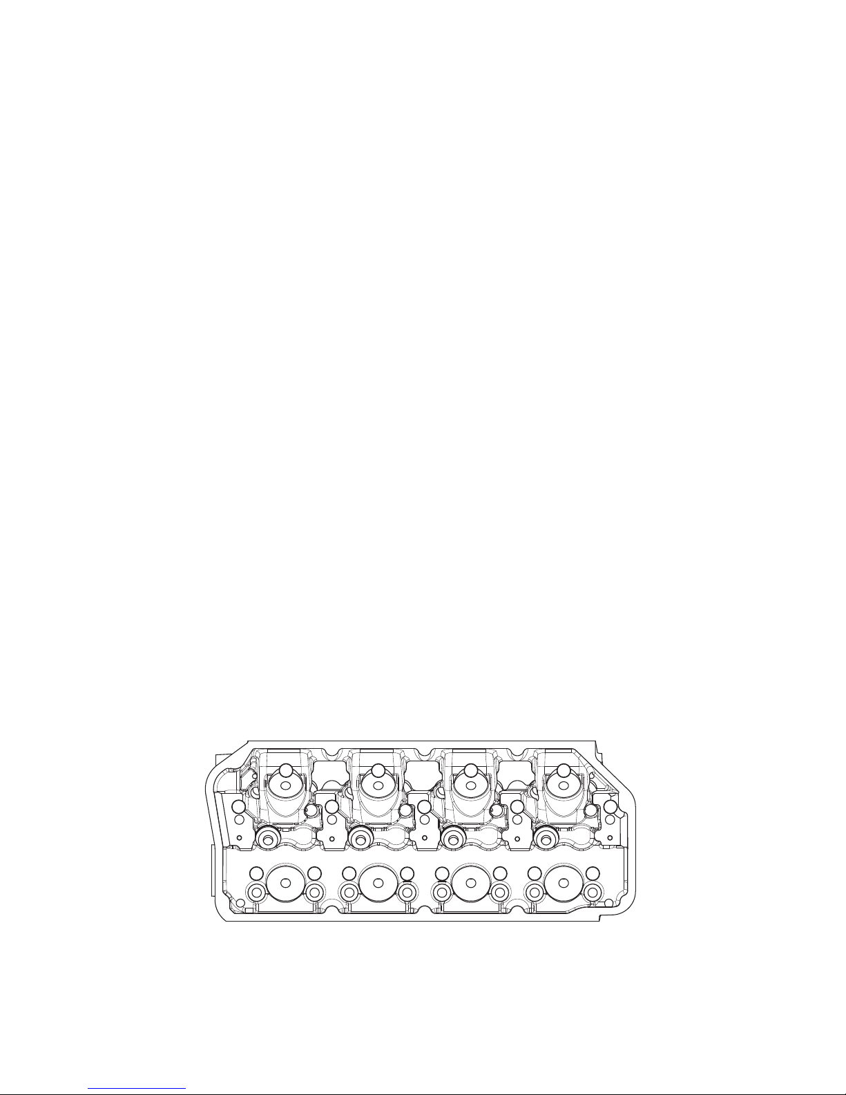
bolt heads and washers. Torque cylinder head bolts in three steps
following the factory tightening sequence (See Figure 1).
SPECIFICATIONS:
Head Bolt Torque: See Figure 1, or use head bolt
manufacturer’s specifications
Deck Thickness: 5/8”
Combustion Chamber Volume: 170 cc
Valve Size (Except for 61169): Intake - 2.320”
Exhaust - 1.940”
Valve Seats: Hardened ductile iron, non-
interlocking, compatible with
unleaded fuel
Valve Spring Diameter: 1.540”
Valve Spring Installed Height: 1.880”
Valve Spring Seat Pressure:
Hydraulic Roller Cam 151 lbs. @ 1.880”
Flat Tappet Cam 133 lbs. @ 1.880”
Valve Spring Open Pressure
Hydraulic Roller Cam 414 lbs. @ .600” Lift
Flat Tappet Cam 349 lbs. @ .600” Lift
Max. Valve Lift: .700”
Coil Bind 1.120”
Replacement Valve Springs: #5821 - Hydraulic Roller Cam
#5792 - Flat Tappet Cam
Victor Jr. Cylinder Head Bolt Torque Spec
(Torque specs below only apply if using ARP Ultra-Torque Fastener Assembly
Lubricant; included with head ARP head bolt kits. If using other fastener
lubricant(s), please use manufacturer’s recommended torque specs.)
First Pass: Torque all bolts, in sequence, to 25 ft./lbs.
Second Pass: Torque all bolts, in sequence, to 40 ft./lbs.
Final Pass: Torque all bolts, in sequence, to 80 ft./lbs..
NOTES: A head bolt re-torque is recommended after initial start-up
and cool-down (allow 2-3 hours for adequate cooling).
Fig. 1 - Cylinder Head Bolt Tightening Sequence
13
17
16
9
12
5
1
8
4
3
7
6
2
10
11
15
14
Edelbrock LLC • 2700 California St. • Torrance, CA 90503
Catalog #61169, 61175, 61179, 61189
Rev. 11/13/14 - QT
Exhaust Side
Tech Line: 1-800-416-8628
Page 2 of 2
©2014 Edelbrock LLC
Brochure #63-61169
 Loading...