

Page 1

Pro-Tuner Users Guide
Edelbrock Corporation
2700 California Street
Torrance, CA 90503
Toll Free Tech Line: 800-416-8628
Office: 310-781-2222
Tech e-mail: edelbrock@edelbrock.com
Page 2

2
Table of Contents
Part I
Part II
Part III
Introduction
Kit Contents
Installation and Setup
................................................................................................................................... 101 Engine Management Concepts
.......................................................................................................................................................... 12Strategies and Methods
................................................................................................................................... 152 Vehicle Installation
.......................................................................................................................................................... 22Fuel System Installation
.......................................................................................................................................................... 30ECU and Main Harness Installation
.......................................................................................................................................................... 36Component and Sensor Installation
......................................................................................................................................................... 37Distributor and Ignition
......................................................................................................................................................... 41Intake Air Temperature Sensor (IAT)
......................................................................................................................................................... 42Engine Coolant Temperature Sensor (ECT)
......................................................................................................................................................... 43Manifold Absolute Pressure Sensor (MAP)
......................................................................................................................................................... 45Idle Air Control Valve (IAC)
......................................................................................................................................................... 46Fuel Pressure Sensor (optional)
......................................................................................................................................................... 47Oil Pressure Sensor (optional)
......................................................................................................................................................... 48Mass Air Flow (MAF) Sensor (optional)
......................................................................................................................................................... 50Throttle Position Sensor (TPS)
......................................................................................................................................................... 51Main Wiring Harness and Engine Wiring
......................................................................................................................................................... 54Oxygen Sensors
......................................................................................................................................................... 59Malfunction Indicator Light
................................................................................................................................... 603 Installing and Configuring the Software
.......................................................................................................................................................... 62System Requirements
.......................................................................................................................................................... 64Installing the Software
.......................................................................................................................................................... 70Installing the Communications Hardware
......................................................................................................................................................... 72USB/Serial Converters
.......................................................................................................................................................... 80Connecting to the Vehicle
.......................................................................................................................................................... 87Application Settings and Preferences
5
7
10
Part IV
Basic Tuning with the Pro Tuner System
................................................................................................................................... 901 Setup Wizard
.......................................................................................................................................................... 94Scaling Setup - Custom Load and RPM Axis
................................................................................................................................... 962 Screens, Indicators and Tools
.......................................................................................................................................................... 99Dashboard
.......................................................................................................................................................... 101MAPs
.......................................................................................................................................................... 104Details
.......................................................................................................................................................... 105Status Bar
.......................................................................................................................................................... 106About
.......................................................................................................................................................... 107System Information
................................................................................................................................... 1083 Tuning Maps
.......................................................................................................................................................... 116Base Fuel Map
.......................................................................................................................................................... 118Volumetric Efficiency Map
89
Page 3

.......................................................................................................................................................... 121Spark Advance Map
.......................................................................................................................................................... 124Target Air/Fuel Ratio Map
.......................................................................................................................................................... 128Accel / Decel Fuel Settings
.......................................................................................................................................................... 132Closed Loop Compensation (CLC) map
.......................................................................................................................................................... 135ECT Fuel Trim Table
.......................................................................................................................................................... 136A/C Load Compensation
.......................................................................................................................................................... 138IAT Fuel Trim Table
................................................................................................................................... 1394 3D Chart Manipulation
.......................................................................................................................................................... 140EDIT Chart Point
.......................................................................................................................................................... 142ROTATE
.......................................................................................................................................................... 144ZOOM chart
.......................................................................................................................................................... 145MOVE view
.......................................................................................................................................................... 146RESET View
................................................................................................................................... 1475 Logging and Data Viewing
................................................................................................................................... 1516 Initial Start Up and Idle Tuning
................................................................................................................................... 1557 TPS Set Points
................................................................................................................................... 1588 Ignition Sync Offset
................................................................................................................................... 1609 OFFLINE Mode
.......................................................................................................................................................... 164OFFLINE LOAD
.......................................................................................................................................................... 165OFFLINE SAVE AS
.......................................................................................................................................................... 167OFFLINE SAVE
.......................................................................................................................................................... 168OFFLINE SAVE and USE ONLINE
.......................................................................................................................................................... 169View Logger Data
3Contents
Part V
Part VI
Advanced Tuning with the Pro Tuner System
................................................................................................................................... 1721 Warm Up Fine Tuning
................................................................................................................................... 1742 Idle Fine Tuning
................................................................................................................................... 1773 Toggle Closed Loop
................................................................................................................................... 1784 VE Estimator Tool
................................................................................................................................... 1805 Adaptive Fuel "AutoTuning" Capabilities
................................................................................................................................... 1836 Oil Pressure Warning Set Points
................................................................................................................................... 1847 Coolant Fan Output
................................................................................................................................... 1858 Coolant Fan Set Points
................................................................................................................................... 1869 Fault Detection and Troubleshooting
................................................................................................................................... 18910 Reset ECU to last programmed setup
Features Available with Pro option only
................................................................................................................................... 1911 Additional Maps
................................................................................................................................... 2032 Flight Recorder
................................................................................................................................... 2063 Virtual Engine Simulator
................................................................................................................................... 2084 Base Fuel Pressure Set Point
................................................................................................................................... 2105 Adaptive Air "AutoTuning" Capabilities
171
190
Part VII
Appendices
................................................................................................................................... 2151 Engine Controller Pinout Sheets
214
3
Page 4

4
................................................................................................................................... 2182 Frequently Asked Questions (FAQs)
................................................................................................................................... 2193 Trouble Codes/Faults
................................................................................................................................... 2224 Maintenance Procedures
.......................................................................................................................................................... 223TPS Replacement
................................................................................................................................... 2255 Glossary
................................................................................................................................... 2326 Additional Resources/Service
Page 5

1 Introduction
Introduction 5
Visit us at: http://www.edelbrock.com
Edelbrock Pro-Tuner Series Electronic Fuel
Injection (EFI)
"Total Engine Management"
That’s the slogan for Edelbrock’s Pro-Tuner EFI Systems, powered by Mototron Electronic
Control Units (ECU).
Pro-Tuner EFI Systems include everything needed to convert any engine to powerful
electronic fuel injection; with user programmable features and full ignition control as well
as fuel delivery. Two performance levels are available: Victor and Super Victor. Both
versions include an Edelbrock Victor or Super Victor EFI intake manifold, fuel rails,
throttle body, wiring harness, injectors, Pro-Tuner software, sensors, fuel pump
regulator, and Mototron ECU with Power PC, 32-bit micro controller.
Victor Systems include a Mototron ECM for semi-sequential injection, while Super Victor
Systems feature fully sequential operation and individual cylinder adjustment of spark
and fuel for complete optimization, plus a software upgradeable Mototron PCM with
advanced features - and expandability for exciting future options. Through your laptop
computer, all critical aspects of engine tuning are adjustable to suit your application. The
simplified user interface allows a tuner to dial-in the behavior of the state of the art
control strategies running within the ruggedized Engine Control Module (ECM).
The proprietary Mototron ECU is extremely durable. It’s completely sealed making it
waterproof and ideal for not only competition vehicles but for marine as well. Once up
and running, Edelbrock’s Pro-Tuner EFI software offers easy-to-use, yet sophisticated
tuning control with user-friendly pull down menus and screens.
Page 6

6
Available separately, Edelbrock offers a Pro USB key which allows access to enhanced
tuning parameters for more experienced calibrators. A Basic USB key is included
standard.
Before reading this manual and installing your new system, it is important to understand
that your Edelbrock EFI system is more than fuel injection. It is an Engine Management
System. In addition to controlling the fueling of your engine, the system will also be
controlling ignition, idle airflow, monitoring sensor health, and running other optional
actuator outputs.
While every effort is made to simplify the installation and calibration process, the most
important tool is the knowledge and experience of the person tuning the engine. Just as
with carbureted engines; the tuner must know the fueling and ignition limits of the
specific engine he or she is calibrating to avoid engine damage and provide the best
reliability and drivability possible. In addition to reading this manual, there are many
other sources of engine management theory, as well as experienced tuners and
Edelbrock experts available to assist with questions that you have. See the “Additional
Resources” section of this manual for more sources of EFI information. It is highly
recommended that the Tuner educate themselves as much as possible in the area of
electronic engine control and calibration theory and technique.
If you run into problems, you may contact our EFI Technical Hotline at 800-416-8628
from 7:00 am to 5:00 pm PST Monday through Friday. You may also contact us by email
at: EFItech@edelbrock.com
READ THROUGH ENTIRE MANUAL BEFORE BEGINNING
•
SYSTEM INSTALLATION!
THIS CONTROL SYSTEM IS INTENDED FOR OFF-ROAD
•
APPLICATIONS ONLY. THE USER ASSUMES ALL RESPONSIBILITY
FOR THE INSTALLATION AND APPLICATION OF THE SYSTEM AND
MUST COMPLY WITH ALL APPLICABLE RULES AND REGULATIONS
GOVERNING USAGE AND EMISSION REQUIREMENTS.
Page 7

2 Kit Contents
Kit #3670 Contents:
Part No. Description Qty.
22-3601 Firewall Bulkhead Plate Kit 1
38-1515 Bulkhead Plates 2
68-0410 Self-Tapping Screws 4
72-1516 Grommet 1 3/4" O.D. 1
24-0301 Ignition Amplifier Kit 1
Introduction 7
Visit us at: http://www.edelbrock.com
68-0410 Self-Tapping Screws 3
37-3517 Victor Pro-Tuner Kit 1
37-0004 RS485 Comms Cable 1
37-0006 USB Software Key (Basic Key) 1
37-0007 Controller ECM (48 Pin) 1
72-1517 ECM Rubber Grommet 3
82-0111 ECM Mounting Washers 3
82-3519 ECM Mounting Bushing 3
38-1600 Mounting Bracket for 48 pin PCM 1
68-4005 1/4-20 x 7/8" PCM Socket Head Screw 3
37-3545 Main Engine Harness w/ 2-Power Relays 1
N/A Padded J-Clamps 4
37-3546 Distributor Harness 1
37-3547 Fuel Pump Harness 1
63-3670 Instruction Sheet - Quick Start Guide 1
63-3615 Instruction Sheet - Distributor 1
63-0507 CD-ROM 1
37-3518 MAT Sensor GM (AC Delco #12160244) 1
72-9952 MAT Sensor Grommet 1
37-1520 Serial to USB Converter 1
63-91147Serial to USB Converter Instructions 1
Page 8

8
37-3548 Malfunction Indicator Light w/ Clip 1
37-7119 1 Bar Map Sensor (Remove Orange Rubber) 1
38-3601 Gen III Map Sensor Bracket 1
37-3528 60 lb/hr High Impedance Injectors 8
67-1570 Injector O-ring Lube 1
37-3529 MSD Distributor w/ Cam Sync MSD PN 23451 1
37-3543 Temperature Sensor 1
37-3542 Oxygen Sensor Switching 1
52-9710 Oxygen Sensor Bung 1
Page 9

Kit Contents 9
Kit #3690 Contents:
Part No. Description Qty.
22-3601Firewall Bulkhead Plate Kit 1
38-1515 Bulkhead Plates 2
68-0410 Self-Tapping Screws 4
72-1516 Grommet 1 3/4" O.D. 1
24-0301Ignition Amplifier Kit 1
68-0410 Self-Tapping Screws 3
37-3523Victor Pro-Tuner Kit 1
37-0004 RS485 Comms Cable 1
37-3524 USB Software Key (Pro Key) 1
37-0005 Controller PCM (80 Pin) 1
72-1517 PCM Rubber Grommet 3
82-0111 PCM Mounting Washers 3
82-3519 PCM Mounting Bushing 3
38-1601 Mounting Bracket for 80 pin PCM 1
68-4005 1/4-20 x 7/8" PCM Socket Head Screw 3
37-3550Main Engine Harness w/ 2-Power Relays 1
N/A Padded J-Clamps 4
37-3546 Distributor Harness 1
37-3547 Fuel Pump Harness 1
63-3670 Instruction Sheet - Quick Start Guide 1
63-3615 Instruction Sheet - Distributor 1
63-0507 CD-ROM 1
37-3518 MAT Sensor GM (AC Delco #12160244) 1
72-9952 MAT Sensor Grommet 1
37-1520 Serial to USB Converter 1
63-91147Serial to USB Converter Instructions 1
37-3548 Malfunction Indicator Light w/ Clip 1
37-7119 1 Bar Map Sensor (Remove Orange Rubber) 1
38-3601 Gen III Map Sensor Bracket 1
37-3528 60 lb/hr High Impedance Injectors 8
67-1570 Injector O-ring Lube 1
37-3529 MSD Distributor w/ Cam Sync MSD PN 23451 1
37-3543 Temperature Sensor 1
37-3542 Oxygen Sensor Switching 1
52-9710 Oxygen Sensor Bung 1
Page 10

10
3 Installation and Setup
Installation and Setup
In this section, you will have access to information on how to physically install the
system in your vehicle, install the sensors and ECU, and begin the setup process to get
your vehicle on the road!
BEFORE BEGINNING!
Visit us at: http://www.edelbrock.com
A clean and trouble free installation of the Pro-Tuner System is greatly enhanced by
taking the time to organize and plan your installation before beginning. Perform the
following:
· Unpack and inventory the system to ensure that you have all the parts, sensors, and
wiring that are listed on the packing list
· Lay the harness and wiring out on a table or the floor to help visualize the placement of
the sensors, connectors and components
· Take your battery to a local auto parts store and have them test it for proper voltage
and current carrying capacity.
· Be sure your engine is in good mechanical condition. Fouled spark plugs, vacuum
leaks, etc. will prevent you from properly tuning your engine!
3.1 Engine Management Concepts
Visit us at: http://www.edelbrock.com
Engine Management Concepts
In this section, we will discuss the general operation of the Engine Management system,
including strategies, controls and methods used to enable the engine to be efficient,
Page 11

Installation and Setup 11
clean, and reliable.
IMPORTANT!
TO AVOID SERIOUS OR FATAL INJURY, NEVER ATTEMPT
TO WORK WITH THE CALIBRATION LAPTOP COMPUTER
WHILE DRIVING VEHICLE.
NEVER PERFORM CALIBRATION ACTIVITIES ON PUBLIC
STREETS OR HIGHWAYS! DISTRACTION AND/OR
INADVERTENT CALIBRATION CHANGES COULD RESULT
IN SERIOUS ACCIDENTS.
Calibration Introduction
Calibration of an EFI system, presents many challenges and opportunities. The
opportunities are to improve the throttle response, drivability, start ability, fuel economy,
reliability, and reduce emissions of almost any engine. The challenge centers around
optimizing a myriad of variables for every operating condition of the engine to achieve
the desired results. While certain parameters can be “learned” by the engine control
computer through various strategies and algorithms; it ultimately becomes the
responsibility of the calibrator or tuner to decide what the ECM should learn, and to make
critical decisions about how the particular engine he/she is calibrating will behave under
various conditions. Just as it takes time and effort to become a proficient carburetion
calibrator; so it will take as much or more time and practice to become a good EFI
calibrator. Do not become discouraged or intimidated. Start with the basics of fuel and
spark control, then gradually work up to cold starting, transient calibration, idle control,
individual cylinder control, and advanced functions and setups. Always remember to start
with conservative values for spark, fuel, etc. to avoid damaging the engine. (Minimal
spark advance with fueling on the rich side of optimum)
Most tuners agree there is great personal satisfaction when an engine with their own
“optimized” calibration is running well. This calibration guide assumes the reader to be
familiar with general engine tuning and concepts, and experienced in the requirements
and limits of the engine being calibrated. Since each engine and application differ; this
manual does not attempt to dictate detailed tuning specifications (such as dictating "X
degrees of spark advance at 5% load and 800 rpm”) rather; its purpose is to familiarize
the calibrator with the interface software, techniques for tuning various strategies, and
provide background information on how they are used. The user assumes all
responsibility for the application and use of the information and Edelbrock system
software & hardware.
While this guide should prove helpful; it is significantly condensed and simplified to allow
the calibrator to quickly reference specific sections. Depending on your specific system
Page 12

12
and the method of interfacing to the engine; some of the strategies described in this
guide may not be visible or may be pre-calibrated for you. Systems also vary as to their
configuration: mass airflow, speed density or speed-throttle, oxygen sensors, ECU, and
so on – slightly altering the calibration process. Descriptions of the functions are usually
available next to the item or in the header of the map to aid the calibrator. The “HELP”
menu in the calibration software also contains much useful information; as well as the
documentation for your system, and can be selected at any time during software usage.
Always use the documentation for your exact system as the primary reference for system
setup and questions.
Ideally, calibration is performed with the vehicle on a chassis dyno where all loads and
speeds may be calibrated under controlled conditions. In cases where dynamometer
running is not possible, the tuner should enlist the help of another to drive the vehicle
while the tuner makes adjustments with the laptop between runs or make table
adjustments based on recorded logger data. Vehicle calibration should ONLY be done
on a closed road-course or drag strip with helmets and all other proper safety
gear in place. Be aware also that some adjustments may be necessary even
after an engine is dyno tuned. Different engine dynos will load the engine
differently and they do not always accurately simulate vehicle conditions. This
is especially true for transient operation (throttle snaps, etc.).
3.1.1 Strategies and Methods
Strategies and Methods
Control System Concepts
The Engine Management System functions by receiving inputs from various sensors,
making calculations and operational decisions, and sending appropriate instructions to
outputs that control devices and actuators. In order to do this, the Engine Control Module
(ECM) converts the analog inputs to digital signals and processes them within the 32 bit
microprocessor. Outputs are conditioned as required for the assigned purpose.
Visit us at: http://www.edelbrock.com
Your Edelbrock system is capable of three different fuel/timing control strategies.
Modeled speed density uses sensor inputs along with a volumetric efficiency (VE) table
Page 13

Installation and Setup 13
to estimate the airflow through the engine. The air fuel target table is used in
conjunction with this calculated airflow to control the injector pulsewidth. The MAP-N
strategy uses a base fuel map that varies as a function of engine speed and manifold
pressure. The desired base injector pulsewidth is displayed in the table. The Alpha-N
strategy uses a base fuel map that varies with engine speed and throttle position. The
desired base injector pulsewidth is displayed in the table. The Alpha-N strategy works
very well for engines with very large camshafts that exhibit very low idle vacuum. The
table below summarizes the advantages and disadvantages to each control strategy.
Modeled Speed Density MAP-N Alpha-N
Advantages
Disadvantages
· If properly setup, does
not require tuning of
temperature based trim
tables
· Direct measurement of
engine load (assuming
the VE table is accurately
defined)
· Can adjust for changes in
engine tuning
requirements if used with
optional mass airflow
sensor
· If properly setup, will be
more consistent as
operating conditions
change
· Requires an accurate
volumetric efficiency
table
· Fuel control units more
difficult to understand
· Mass airflow sensor (if
used) difficult to retrofit
onto older engines
· Relatively quick and easy to
tune
· Base fuel map in units of
injector pulsewidth
· Very common tuning method
used in many available
aftermarket EFI systems.
· Works well and easy to tune
for boosted applications
· Easy to modify calibration if
larger injectors installed
· Does not work well with
large overlap camshafts due
to low idle vacuum
· Requires temperature based
trim tables
· Indirect measurement of
load
· Calibration could be
inconsistent if trim tables are
not properly tuned
· Works well for large overlap
camshafts Not affected by low
idle vacuum signal
· Relatively quick and easy to
tune
· Base fuel map in units of
injector pulsewidth
· Easy to modify calibration if
larger injectors installed
· Idle mixture affected by
closed throttle TPS voltage
drift
· Requires temperature based
trim tables
· Indirect measurement of load
· Does not work well with idle
air control motors.
· Calibration could be
inconsistent if trim tables are
not properly tuned
The engine management system requires sensor data to maintain efficient operation
under various conditions, and to provide feedback to the ECM regarding the current
operating conditions. The sensors needed for basic operation include: ECT (Engine
Coolant Temperature), IAT (Intake Air Temperature) or (Charge Air Temperature), TPS
(Throttle Position Sensor), CTS (Crankshaft Trigger Sensor), MAP (Manifold Absolute
Pressure) sensor, and O2 (oxygen sensor). Other sensors can be added for additional
control information or data acquisition; however, the sensors listed are the minimum
ones required for basic engine control with this system.
When calibrating an engine, the basic goals are to optimize torque and minimize
fuel consumption at every speed and load point. However, there are limits to how
far one can go with this in actual application. In practice, you will be constrained by other
factors and may be limited to values that insure running quality and reliability. This is
called the “calibration window” for that condition. We will discuss cal windows later on.
As you proceed, It is very important to understand that engines will attempt to run in
Page 14

14
many conditions in which they should not be exposed – such as detonation or excessive
temperatures. It is your job as a calibrator to balance all of the factors for your specific
combination and program the best target values into the ECM that you can while keeping
the engine in a safe operating window. There is a desired order in which an engine
control system should be calibrated. A general order of activities is listed below:
1. Verify correct system installation and insure the method of wire and hose
routing will prevent any chance of wear, fraying, or proximity to high
temperatures. Insure software and communication to the ECM is
functioning properly.
2. Perform preliminary calibration activities: load proper sensor and engine
configuration calibrations and limits, set crank trigger offset (& cam offset if
available), scale sensors and map ordinates. It is preferable if the tuner starts with
a known calibration for a similar combination whenever possible; as it greatly
speeds the setup and calibration process.
3. Calibrate under steady state conditions for every engine speed and throttle
position (load) - while optimizing fuel, ignition timing, and airflow – and
completing the various maps at each point.
4. Optimize starting, warm-up, and idle calibrations for various temperatures and
conditions. (Cold starts, hot restart, etc.)
5. Calibrate transient fueling (acceleration and deceleration) parameters if needed to
optimize fuel during non-steady state conditions.
Fundamental Steady-State Engine Calibration Goals
1. Minimize BSFC at part-throttle operating conditions.
2. Maximize Torque at WOT.
3. Stay within emissions constraints.
5. Stay within EGT limits
6. Minimize drastic or erratic map value changes between cells
The important thing to remember is to balance all of the factors to create the best
compromise between them.
For example: as a calibrator, you may be personally focused on running quality. You may
find that running quality continues to improve as you advance the spark at a particular
operating point. Even though running quality may actually improve as spark is advanced
into the knock region – one should not cross those limits in pursuit of optimizing one
variable, because doing so could cause engine damage.
The best calibration attempts to keep each variable in the middle of the window for every
operating point. While this may not always be possible due to operating conditions or
engine hardware and design; every effort should be made to keep away from the edges
of the window. For example, let’s say you calibrated your engine on the lean side of the
wide open throttle air/fuel window to reduce fuel consumption during the race. While it
may be OK for that specific combination at that time, you would have to ask yourself,
1.Is the calibration robust enough if my crew chief advances the cam 2 degrees?
2.Will the engine be OK if fuel quality varies?
3.Will the engine detonate if lugged in gear?
For these reasons and others, it is desirable to stay in the center of the variable’s window
Page 15

whenever practical.
Further calibration tips are contained within this manual and associated with the Pro
Tuner function or map that they correspond to.
3.2 Vehicle Installation
Installing the Victor System in the
Vehicle
Installation and Setup 15
Visit us at: http://www.edelbrock.com
Installing the Victor system in a vehicle is a straight-forward procedure that is not
difficult; particularly if you have experience replacing intake manifolds and basic
automotive electrical knowledge. During this stage, it is helpful to consult a factory
service manual (if available) as well as your system documentation.
Since specific procedures may vary with application, a factory manual should be used to
identify and assist in installation in those instances. Some items that may be unique
depending on the applications are:
1.Firing order
2.Location of #1 cylinder
3.Proper idle vacuum, RPM and ignition timing
4.Ignition advance curve
For proper system function and warranty coverage, it is very important that all
installation instructions be followed during installation and operation. If you do not
understand a procedure, contact the Edelbrock hotline. If you do not have the necessary
skill or tools to perform any of the operations, consult a professional dealer/installer for
assistance.
CHEVROLET V8
System Components:
System ECU (ECM/PCM)
•
Software
•
Ignition Module
•
Wiring harness w/Fuel pump and Main Power relays
•
Fuel Pump harness
•
Ignition Harness
•
MSD/Edelbrock HEI distributor
•
Page 16

16
Intake Manifold - Fuel Rail Assembly
•
Edelbrock High Flow 60 pph Fuel Injectors
•
Four barrel Throttle Body w/integrated TPS sensor & Idle Air Control valve
•
Heated Oxygen sensor w/mounting bung
•
1 bar Manifold Absolute Pressure (MAP) sensor
•
Intake Air Temperature (IAT) sensor
•
Engine Coolant Temperature (ECT) sensor
•
Firewall bulkhead grommet/cover plate assembly
•
Additional Hardware and Parts needed:
Intake Gaskets / other engine gaskets as required
•
Edelbrock/GM/or equivalent
•
5/16” steel tubing (approximate equal length to fuel pickup in tank)
•
Edelbrock Gasgacinch #9300
•
Loctite 598 OEM High Temperature Silicone gasket (O2 sensor compatible)
•
Radiator Coolant - Teflon paste thread sealant
•
Manifold bolt kit
•
Factory service manual & wiring diagrams
•
Preliminary Checklist:
CAREFULLY STUDY AND UNDERSTAND ALL INSTRUCTIONS.
•
Examine the system components and packaging for shipping damage. (If
•
damaged, contact your dealer immediately)
Check all threaded manifold holes.
•
Check all internal manifold passages with a light and wire, making sure they are
•
clean and unobstructed.
Check automatic transmission shift points before removal of the stock system, and
•
adjust linkage after Edelbrock manifold installation for same shift points if needed.
Determining Hood Clearance
1. CHECK HOOD CLEARANCE BEFORE REMOVING STOCK MANIFOLD.
2. Use modeling clay or putty to make five small cones 2-3” high.
3. Position cones on air cleaner at front, rear, each side, and on center stud.
4. Close hood fully and reopen.
5. The heights of the cones indicate the amount of clearance between the hood and
the air cleaner. Record the measurements.
Page 17

Installation and Setup 17
AFTER MEASUREMENT:
COMPARING HEIGHT OF STOCK INTAKE ASSEMBLY AND VICTOR PRO TUNER
ASSEMBLY.
1. Remove air cleaner from stock assembly.
2. Lay a straightedge across top of carburetor flange front to rear.
3. Measure from bottom of straightedge to manifold/block sealing surface of manifold
at front and rear of engine. Record measurements (A & B).
4. Add “A” and “B” and divide by 2 to get average height.
5. Measure your Victor assembly using the same method.
6. Compare the measurements. If the Victor dimensions are taller, subtract the
difference from the current hood clearance to determine the new hood clearance.
Page 18

18
*CAUTION: You must maintain a minimum of ½” clearance between air cleaner
and hood due to engine torque movement. If you have insufficient clearance, a
low profile air cleaner may solve the problem.
EMISSION CONTROLS:
The Edelbrock Victor and Super Victor Engine Management Systems will not accept stock
emission control systems. Check local laws for requirements before installing this system.
Not legal on pollution controlled applications.
FUEL REQUIREMENTS:
Because the Victor and Super Victor systems use an oxygen sensor, you must use
unleaded fuel only to avoid damaging the sensor. If you use leaded fuel in your
application, do not install the O2 sensor and configure the system for no O2 sensors
through the setup Wizard. Fueling will then be managed open loop.
The driver's side sensor is always the primary sensor. Always plug into the
driver side only when using a single sensor. If using dual sensors, the system
will use the leanest bank's sensor to provide closed loop feedback.
AUTOMATIC TRANSMISSION CHECK:
For best performance, economy, and emissions, the shift points must be checked before
and after the manifold change.
*NOTE: This check should only be performed on the drag strip or test track.
With the shifter in drive, accelerate to wide open throttle from a standing start. Hold in
this position, noting speedometer reading when the transmission makes the 1-2 shift.
Run the test again after the manifold change. The shift point should be the same. If the
shift point is not the same – adjustment is necessary. We recommend use of the
Edelbrock Throttle, Cruise control, & Transmission Kick-down Mounting Bracket #8031 or
#8032 with Vortec heads. The Turbo 350 and Turbo 200 feature a window to
accommodate user adjustment of shift points at WOT (Wide Open Throttle).
Page 19

Installation and Setup 19
The 200R4 and 700R4 transmissions require precise adjustments. We
recommend that you consult a reputable transmission shop for final adjustment
once the Victor system has been installed.
INCORRECT SHIFT POINTS CAN RESULT IN TRANSMISSION DAMAGE!
ENGINE CLEANING:
Always perform the installation with a clean engine and engine compartment. Use utmost
care in the cleanliness of ALL parts during the process.
EXHAUST MANIFOLD HEAT RISER:
If your vehicle is equipped with an exhaust manifold heat riser (typically located on the
passenger side of the vehicle under the exhaust manifold), remove the valve for proper
operation.
HEADERS:
For best performance, headers are recommended. Consult Edelbrock or your exhaust
supplier for recommendations on header, pipe, and muffler specifications for your
combination.
INSTALLING THE EFI INTAKE MANIFOLD:
The procedure for installing your new EFI manifold is nearly identical to installing a
carbureted manifold. Always install new gaskets per manufacturer recommendation and
follow the Edelbrock torque specifications for your particular manifold.
PRE-INSTALLATION
Before installing the induction system, take the following steps to ensure successful
installation and performance:
1. Check all components thoroughly for damage when unpacking.
2. Make sure all throttle linkages open entirely and close freely.
3. Make sure all fuel inlet and vacuum ports are free from packing material.
4. Check the installation kit for proper parts.
REMOVING THE STOCK CARBURETOR AND MANIFOLD
1. Disconnect battery.
2. For ease of installation, keep all parts in order.
CAUTION: Do not remove manifold if engine is hot.
3. Drain radiator coolant (radiator drain plug is typically located on lower right facing
engine).
4. Remove gas cap to relieve pressure. Disconnect fuel line and plug. Replace gas
cap.
5. Disconnect all linkage from carburetor such as throttle, throttle springs,
transmission, cruise control and automatic choke.
6. Tag and remove coil wires and sensor wires.
7. Remove previously marked vacuum lines.
8. Remove radiator hose, thermostat housing and thermostat, if mounted on
manifold.
9. Remove all brackets from the manifold.
10.Loosen or remove valve cover bolts for manifold removal and replacement. It may
be necessary to replace valve cover gaskets if broken, to prevent oil leakage.
Page 20

20
PORT SURFACE CLEANING
1. When cleaning old gaskets from head surfaces, lay rags in the lifter valley and stuff
paper into the ports, to prevent pieces of the old gasket from falling into ports and
combustion chambers or valley.
2. When clean, remove paper, making sure that all particles fall on the rags in the
lifter valley.
3. Remove rags, and wipe surfaces clean with rags soaked in lacquer thinner in order
to remove oil or grease.
NOTE: This procedure is necessary to ensure proper sealing.
INSTALLING FITTINGS, PIPE PLUGS, AND STUDS
Do not over-tighten or cross-thread fittings, pipe plugs, studs, or bolts in your aluminum
manifold. Damage to threads or a cracked mounting boss may result unless caution is
used when installing accessories. Use Teflon sealant on all pipe threads.
GASKET SURFACE PREPARATION
CAUTION: Replace all gaskets as recommended. Do not use race-type nonembossed gaskets for street applications. Due to material deterioration under
street driving conditions, internal vacuum and oil leaks may occur. We
recommend Fel-Pro Printoseal gaskets or equivalent. Do not use Fel-Pro Perma
torque Blue gaskets, which are designed for use on stock cast iron intake
manifolds only.
1. Check gaskets on head surface and manifold to make sure they are correct.
Embossed side faces up. NOTE: In some cases, there may be a different right and
left side gasket. Make sure both are placed correctly.
2. Coat head surface and both sides of gaskets with Edelbrock Gasgacinch #9300.
3. Apply Loctite 598 OEM High Temperature Silicone Gasket around water passages
on head surface.
4. Gaskets and surface will become tacky to the touch within a few minutes. Carefully
place gaskets on head surface, aligning ports and bolt holes.
5. Edelbrock recommends the use of Loctite 598 OEM High Temperature Silicone
Gasket instead of end seal gaskets. Apply a 1/4-inch thick bead of sealant across
each end seal surface, overlapping the intake gasket at the four corners.
NOTE: Use the ONLY recommended O2 SENSOR SAFE sealer . Others may
damage the O2 sensor. This method eliminates end seal slippage and
deterioration. For ease of installation, we recommend using an Edelbrock
Manifold Bolt and Washer Kit.
6. Apply Edelbrock Gasgacinch #9300 or equivalent to port surface of the manifold
and to the head surfaces to ensure a good seal.
7. Apply RTV gasket sealer around water passages on the manifold.
8. Surfaces will become tacky to the touch within a few minutes.
INDUCTION SYSTEM INSTALLATION
1. Carefully position manifold and air valve on engine, centering bolt holes with the
bolt holes in the head.
2. Apply thread sealer or Teflon tape to bolt threads where exposed to water or oil.
3. Hand tighten all bolts.
4. Torque all manifold bolts to Edelbrock specifications.
Page 21

Installation and Setup 21
5. Re-connect throttle linkage and springs, transmission, cruise control, and fuel
lines. Check all linkage for smooth throttle operation from idle to Wide Open
Throttle (WOT).
Note: Do not install with a throttle rod, use a cable actuated throttle.
Throttle rods can transfer engine movement to the throttle and possible
lead to binding.
6. Re-tighten the valve cover bolts.
Page 22

22
3.2.1 Fuel System Installation
Visit us at: http://www.edelbrock.com
Fuel System
FUEL SYSTEM BASICS
Because your Edelbrock Pro Tuner system controls fuel delivery very differently than a
carburetor, some conversions to your fuel system may be necessary. Victor/Super Victor
Pro-Tuner electronic fuel injection requires high and constant fuel volume and fuel
pressure. For this reason, a good primary fuel line is critical. A 3/8-inch (minimum)
HIGH PRESSURE fuel line must be used as the primary fuel line.
The fuel that bypasses the injectors must be returned to the fuel tank via a return fuel
line. If your vehicle is already equipped with a fuel pump bypass line, this line can be
used as the return fuel line. If not, the original primary line may be used as the return
line or a new return line plumbed with 5/16” ID steel or high pressure line.
Many late-model cars are equipped with an additional fuel line which runs to a charcoal
canister mounted on the driver side of the vehicle. This line MUST be re-installed after
the fuel system conversion and MUST NOT be used as the return fuel line.
FUEL SYSTEM PLUMBING
Edelbrock recommends parallel plumbing for performance applications. Parallel plumbing
is accomplished by teeing the feed hose from the pump into both fuel rails and
connecting the two outlets to the fuel pressure regulator. See Fig. 2 below. This gives
twice the capacity of series configuration plumbing. It also reduces the fuel velocity in
the fuel rail when compared to series plumbing. If the fuel velocity is too high it may
cause flow disturbance in the fuel rails. A parallel configuration is recommended to
achieve the best cylinder to cylinder distribution.
Page 23

Installation and Setup 23
Figure 2
FUEL PUMP AND FILTER
The Victor/Super Victor Pro-Tuner system uses a single Edelbrock high-pressure electric
fuel pump which is capable of pumping 50 or more psi (depending upon the pump). The
pump relay will prime the system on key-up and shut down the pump if it does not
receive an engine-run signal from the ECU, as in the case of a stall. This safety
precaution is necessary when using a high-pressure fuel system. It is very important that
the fuel flow capacity of the EFI pump exceed your peak demand by 20-25% to avoid
engine damage due to loss of pressure. Electrical connectors should face the front of
vehicle when mounting. Consult your Edelbrock representative for assistance in pump
selection. A high pressure/high volume EFI fuel filter should be mounted between the
engine compartment and the fuel pump. A high quality inlet filter should also be
installed to protect the fuel pump from contamination. See Fig. 2. Consult your
Edelbrock representative for assistance in filter selection. Use the mounting instructions
for the pump and filters that you are using.
RECOMMENDED FUEL PUMP AND REGULATOR KITS
Page 24

24
Up to 600 HP
Edelbrock P/N 35943 - Kit includes fuel pump #3594 and regulator #1728
Up to 800 HP
Edelbrock P/N 17903 - Kit includes fuel pump #1790 and regulator #1729
Up to 1500 HP
Edelbrock P/N 17943 - Kit includes fuel pump #1794 and regulator #1729
FUEL PRESSURE REGULATOR
Fuel pressure is as important as fuel volume, particularly in fuel injection. The Victor/
Super Victor Pro-Tuner system requires that the fuel pressure regulator maintains a
constant pressure at the injectors. It is recommended that Manifold Absolute Pressure
references the regulator diaphragm to maintain constant pressure across all 8 injectors,
regardless of fluctuating manifold pressure (vacuum) level. The fuel that is not injected is
returned to the fuel tank via the return fuel line. Recommended pressure settings vary
with application. Consult your Edelbrock representative for pressure recommendations. A
typical regulator installation is shown in Figure 3.
FUEL LINE SIZES
A high pressure EFI system does not need the same size lines as a low pressure
carbureted engine. A 3/8" diameter (-6 AN) is adequate for engines to at least 750 HP.
A 1/2" diameter line should be used on engines over 750 HP.
RETURN FUEL LINE
There are three options for installing a bypass return line.
1. Use the 5/16 rubber fuel line provided with the system as the fuel return line.
Figure 3
Page 25

Installation and Setup 25
2. Use the vehicle’s existing primary line as the fuel return line with modification to
the pick up as described below.
3. Use the vehicle’s existing return line (if so equipped) as the fuel return line. This
option applies only to vehicles previously equipped with fuel injection. If the
vehicle is not already equipped with a return line, some fuel tank modifications are
required for routing the return line through the sending unit plate back into the
tank. The first two methods listed below require some welding and should be done
by a professional radiator or fuel system repair shop.
RUBBER RETURN LINE METHOD
Drill a 5/16-inch hole in the sending unit plate adjacent to where the main line enters the
tank. This will be the hole for your return line. Insert a short length of 5/16-inch hard
line (available at most radiator shops) into the hole and weld it to the sending unit plate.
The hard line should extend through the hole 1 to 2 inches on each side of the plate.
Connect a length (at least 4 inches) of 5/16-inch rubber return line hose to the hard line
that will extend into the tank. Connect the rubber line to the fuel pickup line using tie
wraps.
BULKHEAD FITTING METHOD
Drill a 9/16-inch hole in the sending unit plate adjacent to where the main line enters the
tank. This will be the hole for your return line. Insert a #6 AN bulkhead fitting (available
at most radiator shops) into the hole, the narrow end of the fitting on the inside of the
plate. Apply a rubber washer or RTV sealant and fasten the fitting to the plate with the
Figure 4
Page 26

26
nut. Connect a length (at least 4 inches) of flexible return line (rubber or braided hose)
to the fitting end. Connect the return line to the fuel pickup line using tie wraps.
NOTE: THIS METHOD REQUIRES NO WELDING OF THE FUEL SYSTEM.
NOTE: Whichever method you use to install the return fuel line, be careful to keep
the end of the line away from the fuel pickup, as shown. Otherwise, aerated return
fuel can be drawn into the pickup.
HARD RETURN LINE METHOD
Drill a 5/16-inch hole in the sending unit plate adjacent to where the main line, enters
the tank. This will be the hole for your return line. Insert a length of 5/16-inch hard line
(available at most radiator shops) into the hole and weld it to the sending unit plate. The
hard line should extend through the hole 1 to 2 inches on the outside of the plate. On the
inside of the plate, the hard line should follow the contours of the fuel pickup line. Bend
the end of the return line away from the sock on the end of the fuel pickup line.
Figure 5
Page 27

Installation and Setup 27
Figure 6
Solder or weld the return hard line to the fuel pickup line.
Page 28

28
Figure 7 - Completed return line installation
FUEL SYSTEM INSTALLATION
1. Disconnect the vehicle battery.
2. Drain the fuel tank.
3. Remove all lines from the tank and carburetor.
4. Remove the fuel tank if sender plate is inaccessible. While fuel tank is removed
from vehicle, it is recommended that it be professionally cleaned in order to
remove any rust or dirt that may have accumulated inside which could damage the
injectors.
5. Remove the sending unit from the fuel tank. Refer to RETURN FUEL LINE METHODS
above for installing the bypass fuel return line.
6. Install the high pressure fuel line next to the original line, which may now serve as
the return line. Use large radius bends. Avoid exhaust components, sharp edges,
and possible wear points. Mount the lines firmly and high in the underbody to
insure that they will not be exposed to ground clearance obstacles or road debris
hazards that could catch or damage the line.
7. If you do not use the original fuel as the return line, route the return line directly
alongside the provided primary fuel line.
8. Mount the fuel pump between the tank and the fuel filter as low and as close to the
fuel tank as possible. The pump is directional. Electrical connectors should face the
front of vehicle. The fuel pump needs to be at or below the level of fuel in the tank.
Page 29

Installation and Setup 29
9. Mount the fuel filter between the fuel pump and the engine.
10.Re-install the modified sending unit plate to the clean fuel tank.
11.Reinstall the fuel tank.
12.Attach the primary line and return line to the sending unit plate on the tank.
13.Re-attach all other fuel lines at the tank (vapor purge lines, etc., if so equipped).
14.Secure the primary and return fuel lines with the provided tie-wraps, or with Adel
clamps if available.
15.Re-attach all fuel lines to the induction system once it has been installed.
NOTE: REMOVE FUEL SENDING UNIT FROM TANK BEFORE MODIFYING. ALL
WELDING AND SOLDERING OF THE FUEL SYSTEM MUST BE PERFORMED BY
A PROFESSIONAL RADIATOR OR FUEL SYSTEM REPAIR SHOP.
INJECTOR INSTALLATION
DO NOT INSTALL FITTINGS WITH RAIL INSTALLED. TORQUE APPLIED TO
THE ASSEMBLY COULD DAMAGE PARTS AND CAUSE FUEL LEAKS!
1. Fasten fuel rail stands (if applicable) to manifold per Edelbrock instructions;
making sure the stands are parallel with the injector bosses in the manifold.
2. Lightly grease the injector O-rings at the top and bottom of injector per Figure 5.
using supplied o-ring lube.
Figure 8
3. Install the top of each injector into the fuel rail; carefully inserting the injector to
avoid pinching or damaging the sealing O-ring. Orient the injector so that the
connector is facing outward. (The outside of the rail has the Edelbrock logo on the
side).
4. Carefully insert the rail w/injectors into the manifold, insuring that each injector
enters the manifold straight and lower O-rings do not get pinched or damaged.
5. Align mounting holes in rail with the rail mounts.
6. Install with hardware provided.
7. Remember to attach the coated injector harness clips to each rail mount, orienting
so the clip is above the mounting hole.
Page 30

30
NOTE: If O-rings are damaged even slightly, they MUST be replaced before
pressurizing system!
Injectors should not bind in the ports. You should be able to rotate
them slightly.
A typical rail installation is illustrated in Figure 9.
3.2.2 ECU and Main Harness Installation
ECU and Main Harness
Figure 9
Visit us at: http://www.edelbrock.com
Page 31
Installation and Setup 31
Installing the Main harness and ECU
To install the system harness, you should first layout the harness in your vehicle to
determine the best layout and routing for your application. Of primary concern, is the
mounting location of the Engine Control Module (ECM/PCM), relays, interface connectors,
and system fusing.
You may choose to mount the ECM inside the passenger compartment similar to OEM
practice. However, the ruggedized ECM also gives you the option of mounting it under
hood. Layout the harness with the appropriate injector connectors corresponding with the
injectors on the engine. Within the available length of the harness, determine potential
mounting locations for the ECM and relays.
Improper installation may cause system
failure and void your warranty.
To mount the ECM and relays correctly, the following rules should be followed:
1. Keep ECM, components, and wiring as far away from heat and exhaust parts as
possible. You may need to install heat shields over certain areas in the engine
compartment to prevent excessive heat from reaching the electrical components.
2. Mount the ECM and relays using only the grommets, bushing's, and washers
provided. Use the Edelbrock ECU mounting bracket shown below for proper
mounting and flexible orientation. These parts are specially engineered to insure
proper isolation of the ECM. Locate the fuse pack so that it can be accessed
conveniently. The fuse pack is shown in Figure 10 below:
Page 32

32
Figure 10
3. Insure that the ECM case does not touch or rub against anything,
particularly metal or wiring. The case MUST be isolated from grounds and
voltage sources.
4. Do not mount hardware in such a manner as to cause stress on the harness. Do
not pull, stretch, or kink wires and connectors. Minimize effect of engine torque
movement on short sections of harness. Improper installation can cause
intermittent wire or connector failure or total loss of connection.
5. Route harnessing to avoid sharp edges, heat, and wear points. Clamp harnessing
with approved clamps and clips. - Do ALL installation work with the vehicle battery
disconnected.
6. A typical PCM under-hood mounting installation is shown in Figure 11.
Page 33

Installation and Setup 33
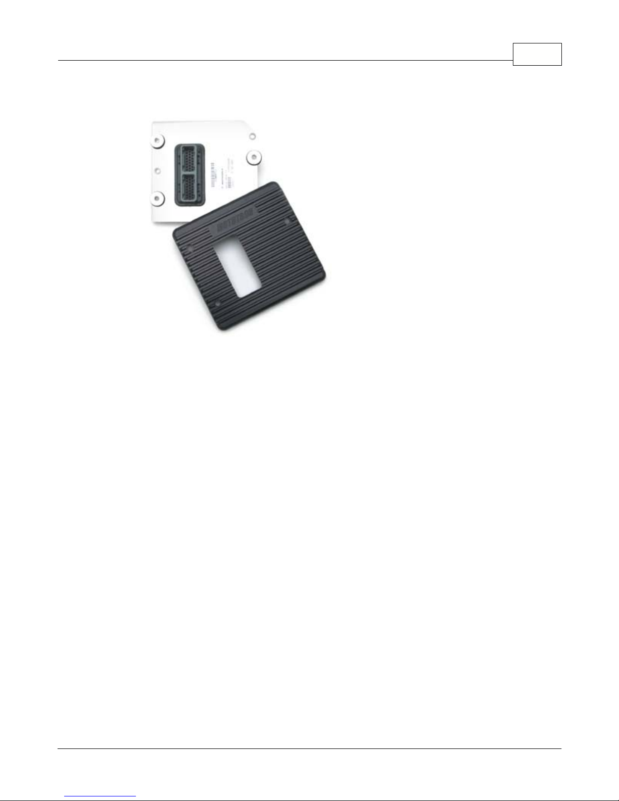
Figure 11 - 80 pin Super Victor PCM
The ECM (48 pin) or PCM (80 pin) controllers mount using specially designed bushing's
and isolation grommets.
When installing the mounts, first install the rubber grommets into the 3 mounting holes.
Insert the bushing from the BACKSIDE of the grommet. Finally, mount to the desired
surface using the provided retaining washer on the top side of the grommet and a 6mm
X 1.0 or ¼-20 screw. Figure 12 below shows the 48 pin ECM with mount installed without
the top retaining washer yet added.
Page 34

34
Figure 12
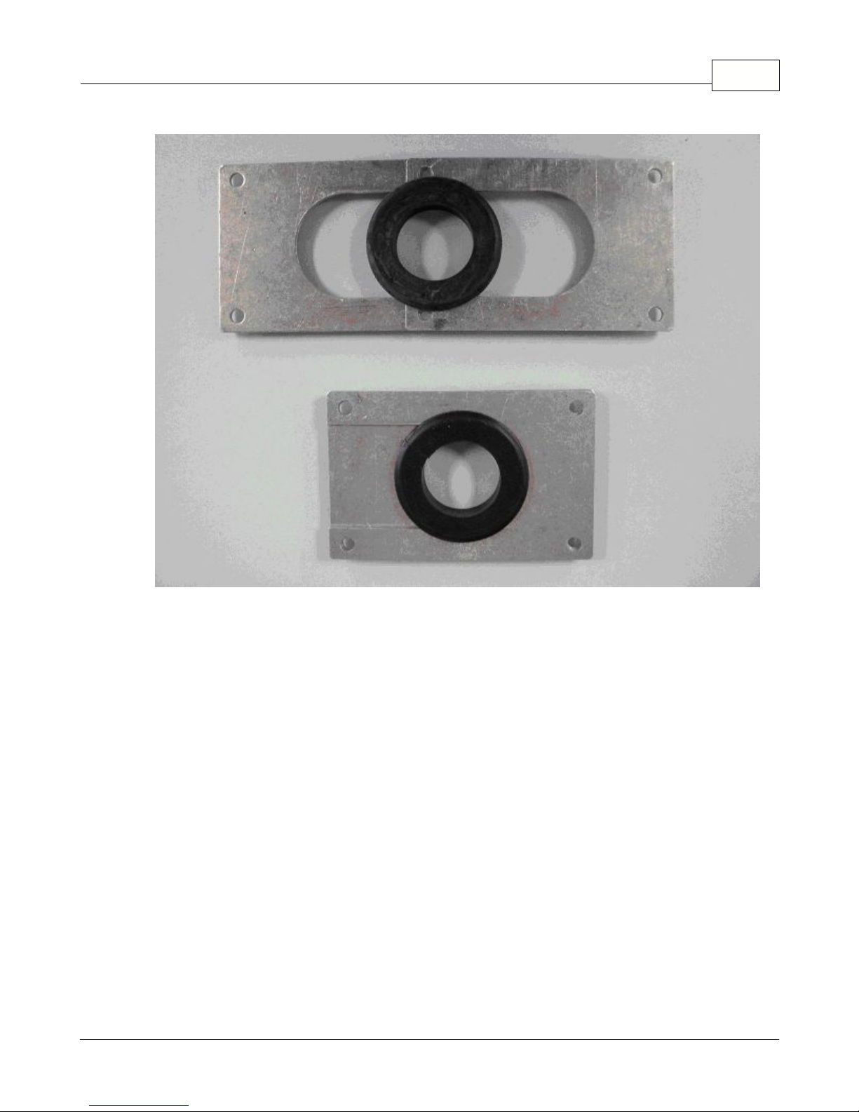
To mount the ECM or PCM inside the vehicle, a hole will have to be made in the firewall
for the harness and connectors to pass through. A firewall bulkhead grommet and cover
plate is included to seal the hole and support the harness where it passes through the
firewall, or you can make your own.
1. To run the harness into the passenger compartment, select the appropriate
location for the harness to pass through for your vehicle – making sure you have
access from the inside of the vehicle and that no components are in the way or can
be damaged during the process.
2. Use the grommet and cover plate assembly as a template. Mark the outline on the
firewall. - Using a hole saw, nibbler, or chassis punch, create a 2” x 2-3/8”
rectangular hole in the firewall – being sure to center the hole in the template
outline. De-burr all edges when finished.
3. Carefully work the harness through the firewall, passing the 32 pin (PCM only)
connector through first, followed by the other connectors. The ECU connector
covers may need to be temporarily removed in some cases to get them through
easily. - Install the firewall plate with the screws provided by slicing the O-ring and
wrapping it around the main harness bundle. Slide each side over the grommet
and harness until the mounting holes line up as in figure 8. Fasten to the firewall.
Use of a silicone sealant between the plate and the firewall is optional. See Figure
13.
Page 35
Installation and Setup 35
Figure 13
Before proceeding further with harness installation, install and mount all sensors and
components.
Page 36

36
3.2.3 Component and Sensor Installation
COMPONENT AND SENSOR OVERVIEW:
The diagram below identifies the location of the major components of the Pro-Tuner
electronics. Not shown below is the air temperature sensor as it is normally mounted in
the air cleaner base.
Page 37

3.2.3.1 Distributor and Ignition
Distributor and Ignition
Installation and Setup 37
Visit us at: http://www.edelbrock.com
The Pro-Tuner Distributor with Cam-Sync is designed for use with our Victor Pro-Tuner
EFI systems for the Small Block and the Big Block Chevrolet. The distributor includes an
adjustable hold down collar (to accommodate various deck heights and custom intake
manifolds), a large distributor cap, and the mechanical advance is locked out. It is
equipped with a steel distributor drive gear. The Pro-Tuner distributor also features a
Magnetic Crank Pickup and uses a Hall-Effect Cam-Sync Pickup with LED indicator for the
Camshaft Sensor. The Cam Sync has a 12” lead and a 3-prong Weatherpak connector.
The crank trigger has an 8” lead and 2-prong Weatherpak connector.
Page 38

38
DISTRIBUTOR KIT CONTENTS
· 1 Pro-Tuner Distributor
· 1 Rotor (MSD #8421) Installed
· 1 Distributor Cap (MSD #8408) Installed
· 1 Wire Retainer
· 2 1.5” Long, Self Tapping Screws
· 1 Distributor Gasket
· 2 O-Rings
· 1 Tube of Assembly Lube
IMPORTANT INSTALLATION NOTES
· DO NOT use a Solid-Core type spark plug wire set, such as copper core, etc. You must
use a suppression type spark plug wire. Failure to use the correct wires will cause
electrical interference with the Engine Control Module.
· When installing the distributor, make sure to disconnect the vehicle’s battery BEFORE
beginning the installation.
· If the drive gear is ever replaced, you must use a MSD #8531 distributor drive gear
due to the .500” diameter drive shaft.
· HALL-EFFECT PICKUP LED OPERATION: The LED is on whenever the magnet is NOT in
front of the pickup. The LED Turns off when the magnet passes over the center of the
pickup (approximately 40°)
· This Distributor has a steel drive gear, check with your camshaft manufacturer for cam
compatibility with this gear.
· A white dot is located on the distributor base directly under the #1 cylinder
post. See figure 14 below for proper orientation.
INSTALLATION PROCEDURE
1.Loosen the adjustable slip collar, Install the Distributor into the engine without the
gasket installed, make sure the oil pump shaft is fully engaged, slide the slip the collar
down to sit against the manifold. Tighten the collar and remove the distributor. Tighten
the set screws on the collar and install the gasket.
2.Rotate the crankshaft in the direction of normal rotation until cylinder #1 is coming up
on the compression stroke. Stop turning when the crankshaft is at 22° BTDC.
3.Install the distributor, with gasket and cam gear lubricated, so that the rotor comes to
rest pointing at what will be the #1 terminal on the cap. Position the cap such that #1
is in the Location shown on the drawing below. You may need to remove and reinsert
the distributor a few times to get the alignment correct. Make sure that the distributor
seats down completely and has fully engaged the oil pump drive. You may need to
rotate the oil pump shaft to ensure it is engaged properly.
4.Lift the rotor by hand to make sure that there is adequate end play. Lack of end play
indicates that the rotor shaft is bottomed out on the oil pump shaft. If there is no end
play readjust the Slip Collar as mentioned above.
5.Align Distributor cap clips parallel with the firewall, Hall Effect sensor should be
pointing toward the forward drivers side of the engine. See Figure 14.
6.Tighten Distributor hold down clamp.
Page 39

Figure 14
Installation and Setup 39
INSTALLATION PROCEDURE O-RING SEALS
The Pro-Tuner Distributor features an o-ring groove in the uppermost bottom land of the
housing in order to seal the oil gallery. The o-ring should only be installed if the block
has been modified. See Distributor Specifications for procedure.
CHECKING THE DISTRIBUTOR DRIVE GEAR MESH
It is recommended to check for proper gear mesh between the drive gear on the
camshaft and the drive gear on the distributor. In order to check the mesh, coat the
distributor gear with the supplied assembly lube and install the distributor into the
engine. Rotate the engine several revolutions and remove the distributor. The mesh
pattern in the lube should be even and in the middle of the gear. Adjust the slip collar to
obtain the proper mesh, if necessary.
CHECKING THE OIL PUMP TO DISTRIBUTOR SHAFT OVERLAP
After checking the drive gear mesh. it is very important to have the proper overlap
between the the distributor shaft and the oil pump shaft.
The tongue of the distributor shaft should sit into the oil pump shaft groove by a
minimum of 1/4”. Check this measurement according to the procedure below:
1.Measure the distance between the base of the slip collar and the tip of the distributor
shaft.
2.Using a straight edge, measure the distance from the intake manifold distributor flange
to the top of the oil pump intermediate shaft.
3.Subtract the measurement from Step 1 from the measurement taken in Step 2. This
difference is the overlap. If there is too much, or not enough clearance, a shorter or
longer oil pump drive shaft will be required.
4.Lightly tighten the hold down clamp so that the distributor can still be turned to
determine final setting when checking the timing.
5.Re-attach the distributor cap. Make sure the rotor is still pointing to #1.
6.Install your spark plug and coil wires and connect the distributor to the wiring harness.
Page 40

40
Make sure to install the spark plug wires one at a time and verify they are in the
correct position. A wire retainer is supplied to secure the wires to the cap. Align the
retainer with the mounting bosses, and use the supplied 1.5” self-tapping screws to
secure the retainer.
ROTOR PHASING
Rotor phasing is defined as the alignment between the rotor tip and the distributor cap
terminal when the spark occurs. This position can be very important to your engine’s
performance. If the alignment is incorrect, the spark will jump to the next closest
terminal, or another ground resulting in a misfire and loss of power. In applications with
extreme cylinder pressures, such as with nitrous or forced induction, correct rotor
phasing increases in importance. More voltage is required to ionize the plug gap and if
rotor phasing is off, the spark is more apt to find an easier path to ground rather than
the correct cap terminal. This may result in severe engine damage.
CARE AND MAINTENANCE
Periodically, visually inspect the cap terminals and rotor tip for wear and look for traces
of carbon tracking where spark scatter occurs. Check your spark plug wires for burns or
tears. It is also recommended to periodically test the resistance of the wires. See for an
exploded view of the distributor and its parts.
Figure 15
Page 41

3.2.3.2 Intake Air Temperature Sensor (IAT)
Intake Air Temperature Sensor
Installation and Setup 41
Visit us at: http://www.edelbrock.com
Installing / Replacing the Intake Air Temperature (IAT) sensor
The Intake Air Temperature sensor is a thermistor device which measures air
temperature. This sensor must be installed into the air cleaner base. Drill the air cleaner
base with a 3/4” drill, deburr any sharp edges, install the sensor grommet, then slide the
air temp sensor into the grommet. This sensor is usually placed in the rear of the base
for best appearance.
Page 42

42
3.2.3.3 Engine Coolant Temperature Sensor (ECT)
Engine Coolant Temperature Sensor
(ECT)
Visit us at: http://www.edelbrock.com
Installing / Replacing the Engine Coolant Temperature (ECT)
sensor
The engine coolant temperature sensor is a thermistor device which measures coolant
temperature. It should be screwed into the coolant passage of the intake manifold near
the thermostat housing to measure coolant before it exits the engine on its way to the
radiator. It has 3/8 NPT pipe thread and comes with a thread sealant pre-applied.
Page 43

3.2.3.4 Manifold Absolute Pressure Sensor (MAP)
Manifold Absolute Pressure (MAP)
Installation and Setup 43
Visit us at: http://www.edelbrock.com
Installing / Replacing the Manifold Absolute Pressure (MAP)
sensor
The MAP sensor measures pressure in the intake manifold. (A pressure below
atmospheric is typical in a running engine, and is sometimes called vacuum when the
value is referenced to atmospheric baseline.) The manifold pressure is low (highvacuum) in a light load condition, while in a high load condition – the pressure will rise
(low vacuum). Manifold pressure provides the ECM information that helps the system
determine the load on the engine so the appropriate output changes are calculated and
executed.
The MAP sensor must have an unobstructed signal to the intake manifold plenum: either
at the throttle body below the throttle blades, or in the plenum itself. A small bracket is
supplied to mount the MAP sensor to one of the 4 throttle body hold down bolts/studs. A
Page 44

44
small length of vacuum line (not supplied) should be installed between the MAP sensor
and the vacuum port reference location. Replacement of sensor should be done using the
original mounting hardware.
Note: If the MAP sensor has an orange ribbed sleeve on the reference port,
remove it prior to installation. It is not necessary for proper operation.
Page 45

3.2.3.5 Idle Air Control Valve (IAC)
Idle Air Control Valve
Installing / Replacing the Idle Air Control valve (IAC)
Installation and Setup 45
Visit us at: http://www.edelbrock.com
The Idle Air Control (IAC) valve is controlled by the ECM and tailors airflow to help
maintain a set point speed at idle. The behavior of the valve can be calibrated for your
combination through the laptop Pro Tuner software. The IAC comes installed on your
system throttle body. Replacement of the valve is through removal of the 2 mounting
screws, remove old valve, replace gasket, and install new valve.
Page 46
46
3.2.3.6 Fuel Pressure Sensor (optional)
Fuel Pressure Sensor
Visit us at: http://www.edelbrock.com
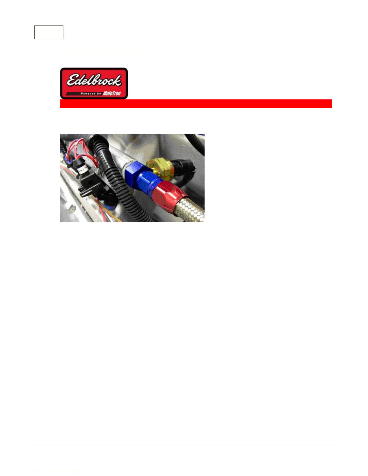
Figure 16
Installing / Replacing the optional Fuel Pressure Sensor
An optional fuel pressure sensor may be used with your system to provide additional
information to the ECU and for readout on digital smart gauges and displays over the
CAN network. It is also used by the system for automatic fuel pressure compensation if
the sensor is in the system. The pressure sensor should be mounted in the fuel rail or
crossover line prior to the fuel regulator. In all cases, but especially if the rail is drilled
and tapped for the 1/8” NPT thread: cleanliness is a must to avoid contamination of the
fuel system and potential engine or injector damage. After machining and during
assembly/disassembly – clean the rail assembly and associated lines thoroughly. Make
sure there are no chips, particles, or overhanging burrs that could break loose.
A typical sensor installation is shown in figure 16.
Page 47

3.2.3.7 Oil Pressure Sensor (optional)
Oil Pressure Sensor
Installation and Setup 47
Visit us at: http://www.edelbrock.com
Figure 17
Installing / Replacing the optional Oil Pressure Sensor
An optional Oil pressure sensor may be used with your system to provide additional
information to the ECU and for readout on digital smart gauges and displays over the
CAN network.
The sensor also enables the low pressure warning limit array. This table allows you to set
the minimum oil pressure for your engine over the RPM range. If the pressure drops
below your calibrated value, the MIL (Malfunction Indicator Lamp) will light to alert the
driver of the condition.
The sensor should be installed as close to an engine oil gallery as
possible and away from exhaust heat.
The sensor features a 1/8”NPT thread and can be used in addition to standard oil
pressure sender units. Use every precaution to prevent dirt or debris from entering
lubrication system during installation. A typical sensor installation is shown in figure 17.
Page 48

48
3.2.3.8 Mass Air Flow (MAF) Sensor (optional)
Mass Air Flow (MAF) Sensor
Visit us at: http://www.edelbrock.com
Figure 18
Installing / Replacing the optional Mass Airflow (MAF) Sensor
Your Victor or Super Victor System has the capability to run a GM digital Mass Airflow
sensor (MAF). A MAF sensor will feed the ECM airflow information which is used in the
control calculations and used to auto-calibrate the Volumetric Efficiency map.
The MAF can be used only for the auto-cal OF VE during dyno testing, or it can be run all
of the time; constantly adjusting for changes in airflow due to wear or engine
modifications. The sensor that should be used is a 1999-2002 GM # 25318411 or the
25341604
tuning session, be sure to turn the sensor off by selecting "none" in the MAF section of
the setup wizard. This will prevent Mass Airflow sensor faults during later operation.
In high horsepower applications, your system is capable of running two of these sensors
in parallel to keep restriction to a minimum. Consult your Edelbrock representative for
information regarding adding and using a second sensor.
The mounting of the sensor is very important to accurate measurement and operation.
The sensor should be mounted as far away from the throttle body as possible (a
minimum of 12”) and between the air filter and throttle body. All tubing and bends
should be smooth with even cross-sectional area. Allow a minimum of 8” of straight
tubing in front of the sensor so that airflow is entering as straight as possible into the
sensor. Follow the factory method of plumbing where possible. Figure 18 shows a sensor
85 mm sensor from the '02 Corvette Z06
. If the sensor is only enabled for the
Page 49

with a recommended sensor inlet tube installed.
Installation and Setup 49
Page 50

50
3.2.3.9 Throttle Position Sensor (TPS)
Throttle Position Sensor (TPS)
Visit us at: http://www.edelbrock.com
The Throttle Position Sensor (TPS) comes installed on your throttle body and should
require no mechanical adjustment. Scaling of the sensor is accomplished through the
Setup Wizard.
When replacing the sensor, the TPS scaling of the min and max values should be
recalibrated through the Setup Wizard. It is also a good idea to reset the TPS
calibration in the setup wizard or from the TOOLS menu (SUPER only) a second
time after the engine idle is tuned in and your final throttle blade setting is
reached.
Page 51
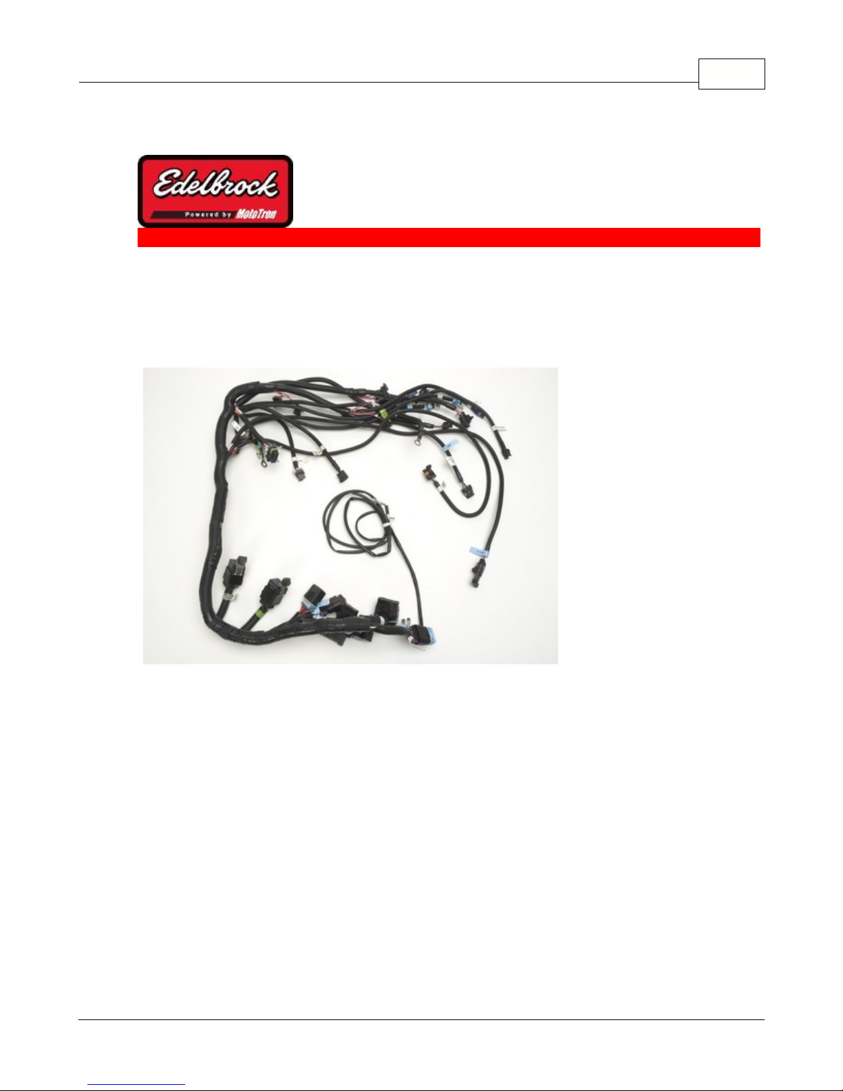
3.2.3.10 Main Wiring Harness and Engine Wiring
Main Wiring Harness and Engine
Wiring
Installation and Setup 51
Visit us at: http://www.edelbrock.com
Figure 19
Once all sensors have been placed, the harness can be routed and connected to each.
Lay the harness out and become familiar with each connection. Do not rush the harness
installation. Take some time to plan the routing of each branch. This will improve both
the look and reliability of the installation. See Figure 19. Before installing the harness,
be sure vehicle battery is disconnected. For all GM applications, odd numbered injectors
go along the driver side fuel rail and should be retained by the clips at each rail mount
screw. Bend the clamp as required to hold the conduit. Even numbered injectors, along
with the TPS, ECT, and MAF sensor connector branch go along the passenger side rail
and should be retained the same way. Route & retain wiring to protect it from heat and
vibration and for a clean, professional looking installation. A little extra time spent
routing the harnessing can make a big difference. This includes spark plug wire routing
as well. Plug in injectors and sensors into the connectors labeled for each. On a GM
engine model, the 1,3,5,7 cylinders are front-to-back on the driver side; while the
2,4,6,8 cylinders are on the passenger side.
It is important that the system has reliable power and ground connections. Attach the
Page 52

52
ground wires, fuel pump harness and ignition harness ground black leads to the same
point using clean & paint-free bell housing bolt connection. Alternatively, you may
connect the system grounds to the same point on the engine as the battery negative
lead. Insure that the engine/transmission is grounded to the chassis and body as well.
See Figure 20 for system Grounding at bell housing. Note Negative battery cable and
paint removed from bell housing under terminal contact area.
Figure 20
If space is confined, an alternative method is to run system power to a firewall mounted
insulated hot-stud and a single 6/8 gauge wire to the starter solenoid.
Connect ignition key-switch lead to the operator ignition switch. The switch should
•
be capable of maintaining uninterrupted +12V power to the system in the “On”
position, “Crank” position, as well as the transition between the two. Many older
vehicles (pre 1974) have ignition switches that bypass power from a ballast
resistor during crank and these systems typically have a momentary “dropout”
between the Run and Crank positions.
These types of ignition switches ARE NOT COMPATIBLE with your Edelbrock
Pro-Tuner system.
If you have such a switch; it must be replaced with a newer non-interruptible
version for proper operation.
Connect remaining wires, including fuel pump and ignition harnesses. Unused
•
connectors should be coiled and secured away from dirt, debris, and heat.
Page 53

Installation and Setup 53
Once all connections are made. Verify that all fuel lines and fittings are tight.
•
Reconnect vehicle battery. If you have questions regarding wiring and connections;
refer to the wiring diagrams included in the help section and your vehicle wiring
schematics.
Turn key switch to “On” or “Run” position. The fuel pump will turn on and run for
•
approximately 4 seconds. It will then shut off. Turn key switch off for 15 seconds.
Turn on again and inspect the system for fuel leaks.
Set fuel pressure regulator to desired pressure (if regulator is an adjustable type)
•
while pump is running. Repeat key-off and key-on cycle as many times as required
to purge air, set pressure, and verify fuel system is leak free. Fuel pressure should
be rechecked at idle after engine has been configured.
Do not crank the engine until the system has been configured
using the Setup Wizard in your Pro-Tuner software.
Page 54

54
3.2.3.11 Oxygen Sensors
Oxygen Sensors
Visit us at: http://www.edelbrock.com
Figure 21
Installing / Replacing Oxygen Sensor(s)
The exhaust gas oxygen content is determined by the oxygen sensor. The sensor signals
the ECU, which compensates when the air/fuel mixture is either rich or lean. If the
exhaust system is already configured for an oxygen sensor port, simply replace existing
sensor with the Edelbrock 4 wire sensor. Route and secure wire and connector away from
exhaust heat. Allow enough slack for exhaust pipe movement.
If your exhaust system does not have an O2 port, you will need to weld the included
threaded bung into the exhaust pipe. See Figure 21.
It is recommended that the O2 sensor installation be performed by
a professional muffler shop.
1. Double check header gaskets, replacing if necessary.
2. Drill a 1/2-inch to 9/16-inch hole in the driver-side header collector reducer, as
close to the engine as possible in the header collector (1" to 3" forward of flange
minimum)
NOTE: Before drilling, make sure the O2 sensor will be mounted at a slight
downward angle in the top half of the exhaust pipe and within reach of the harness
connector. Check to insure adequate clearance for the sensor, taking into
consideration engine movement.
Page 55

Installation and Setup 55
3. Fit the provided fitting into the hole in the exhaust pipe and weld into place.
4. Once it has been welded into place, clean the threads in the center of the fitting. If
your exhaust is coated tap bung threads to ensure a good ground for the 02
sensor.
5. Thread the O2 sensor into the fitting. A high-heat anti- seize compound has been
applied to the sensor threads.
NOTE: The O2 sensor has 18mm x 1.25 spark plug threads.
6. Attach the O2 sensor to the main system harness driver side connector. Refer to
the MAIN SYSTEM HARNESS section of this manual
NOTE: UNLEADED FUEL MUST BE USED ONCE THE O2 SENSOR HAS BEEN
INSTALLED.
COATED HEADERS: Use a digital OHM meter to measure the resistance between
cylinder head bolt and the body of the installed 02 sensor. The reading should be
less than 2 OHMS. If it is more, you need to provide a ground to the 02 sensor
mount.
Wideband (UEGO) Installation
A wideband oxygen sensor is an optional feature which allows very accurate AFR
measurements across a wide range of air/fuel ratios. The appropriate sensor must be
chosen in the setup wizard. With the 48 pin ECM the sensor and conditioning module are
a plug-in installation. To install a wideband/s in the 80 pin PCM controller, follow the
instructions below:
**IMPORTANT**
If you decide to use a single or dual MotoTron or Edelbrock wideband oxygen
sensor (UEGO) with external 0-5V conditioning - instead of the standard heated
switching style (HEGO) with your 80 pin PCM, you must move 2 wires to
different pins in the PCM connector.
While this procedure is straight forward, it is critical that the procedure is followed
exactly to insure proper connection and prevent damage to your wiring harness.
The wideband sensor installs into the exhaust collector exactly the same way as the
standard O2 sensor. The sensor bung should be welded as close to the engine as the
collector allows to insure adequate heat is present at the sensor during idle and light load
conditions.
Connect the conditioning module to the sensor per the kit instructions. Next, the
module’s output needs to be connected to the PCM/ECM. The module plugs into the same
connector/s on the engine harness as the standard switching style oxygen sensor. For
the 48 pin ECM, no other modifications are necessary.
For the 80 pin PCM however, 2 wires need to be moved in the PCM connector. To move
the wires, follow the steps below:
(NOTE: to unplug the connectors from the ECM/PCM, simply squeeze the connector
releases on each side of the connector to release it from the ECM/PCM and pull straight
out). See Figure 22.
Page 56

56
1) Locate the “A” connector on the PCM harness plugs. It is the largest of the 3
connectors and contains 32 pins. The pins are numbered on the bottom side. Remove
from PCM.
2) The cover of the connector must now be removed. Cut the tie-strap holding the
harness bundle to the cover.
3) Four lock tabs retain the cover to the connector. Press 2 tabs on the same side;
unlocking one side at a time – and remove the cover.
4) Note the backside of the connector and the numbers in each corner to help identify pin
numbers. Note also the blue plugs sealing the connector where no wires are present.
With small pliers, grab the plug firmly and pull the plug from the number A7 position. If
2 sensors are installed, also pull the plug from the number A10 position. Save the plugs
for re-installation. See Figure 23.
Figure 22
Page 57

Installation and Setup 57
Figure 23
5) Before the signal wire/s can be relocated, they must be unlocked from the connector.
On one end of the connector there is a white tab and on the other end is 2 white tabs.
With a small screwdriver – push in on the single white tab as shown. You will feel it
unlock as the dual white tabs on the other end protrude out. Now the terminals are
unlocked. See Figure 24.
Figure 24
6) At this point it is important to handle the connector and wires gently to avoid damage
or having a wire pull partially out without realizing it. Locate the wire in A13 (it will be
the same color as the wire in your driver O2 sensor connector). With great care, pull
the wire STRAIGHT out of the connector. Do not jerk the wire or it may pull out of
the terminal, leaving the terminal stuck in the connector. A good method is to install
some soft rubber onto the jaws of a needle-nosed pliers and grasp the wire close to the
connector to aid in pulling the wire & terminal straight out. With the soft-jawed pliers you
must use extreme caution not to squeeze too hard and crush the delicate wire. For
installers who do the conversion often, a special pin removal tool is available to make the
task easier.
7) Relocate the loose wire/terminal from A13 to the A7 position. Push the wire all of the
way in. You should feel it seat into position. To be sure, check the underside of the
connector and note if the shiny terminal in A7 is fully seated. Install a blue plug into A13
to seal the connector.
8) If 2 sensors are used, a second wire must be moved. Using the same procedure, pull
the wire/terminal from A2 and insert it into A10. Install a blue plug in A2 to seal the
connector.
9) Check the underside of the connector to be sure ALL wires are still fully seated. While
gently squeezing the wires into the connector to keep the wires seated; use the side of a
screwdriver to push in on the dual white lock tabs on the side of the connector. When the
lock is snapped into place – recheck the underside to insure all terminals have been
captured fully seated. See Figure 25.
Page 58
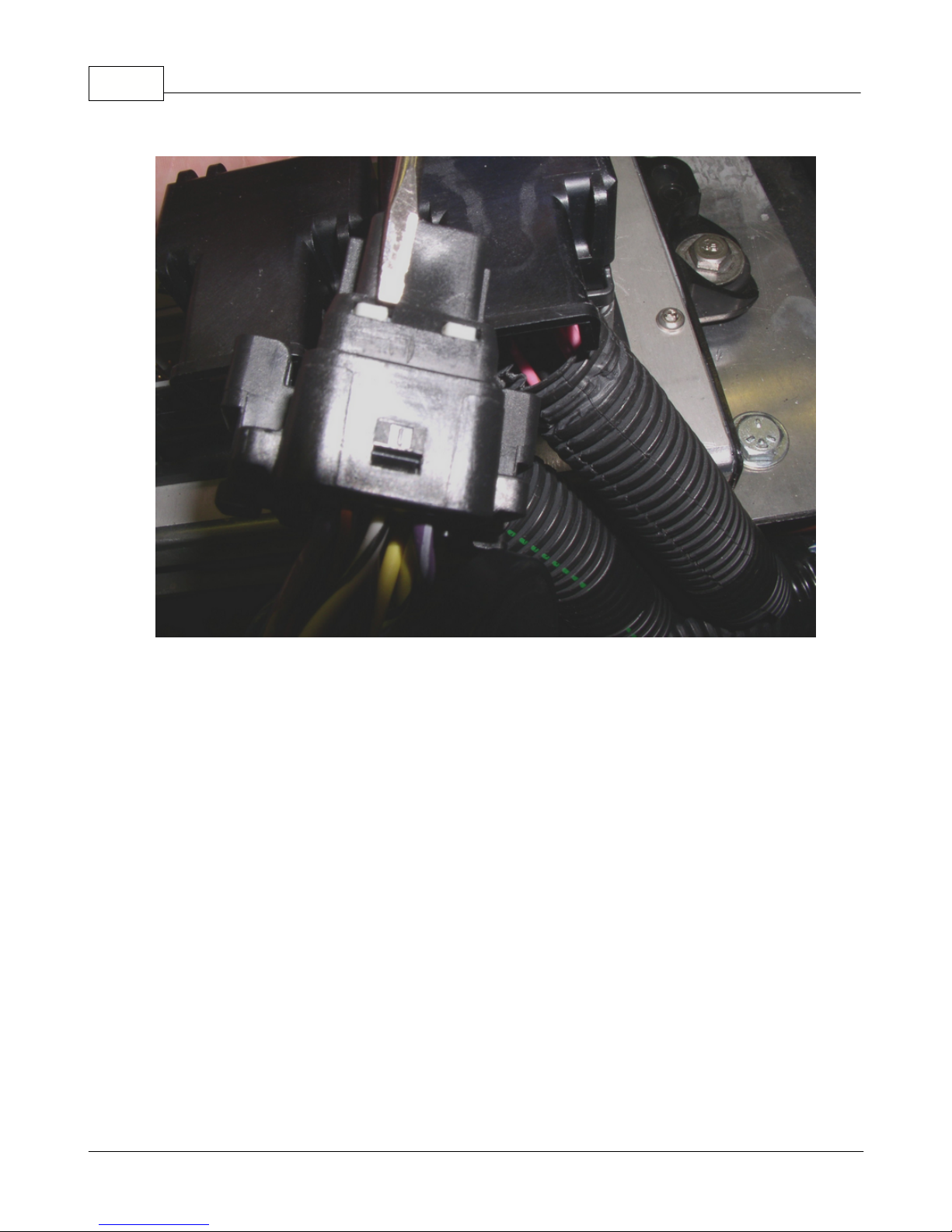
58
Figure 25
Plug the connector/s back into the PCM. Reinstall the connector cover and re-strap the
harness bundle to the cover.
To return to the switching style sensor, reverse the procedure to put the wires
in their original location. Check the wiring schematics for guidance if needed.
Page 59

3.2.3.12 Malfunction Indicator Light
Malfunction Indicator Light
Installation
To mount the Malfunction Indicator Light (MIL), drill a 5/16" hole in a suitable panel.
Insert the MIL into the hole with the orange light facing toward you. Locate the MIL
circuit in the engine harness. It is near the expansion connector. See picture below.
Installation and Setup 59
Visit us at: http://www.edelbrock.com
Connect one wire of the MIL to the orange/white wire labeled "MIL" in the harness.
Connect the other MIL wire to a key-on 12V power source. Polarity does not matter. See
diagram below.
Page 60
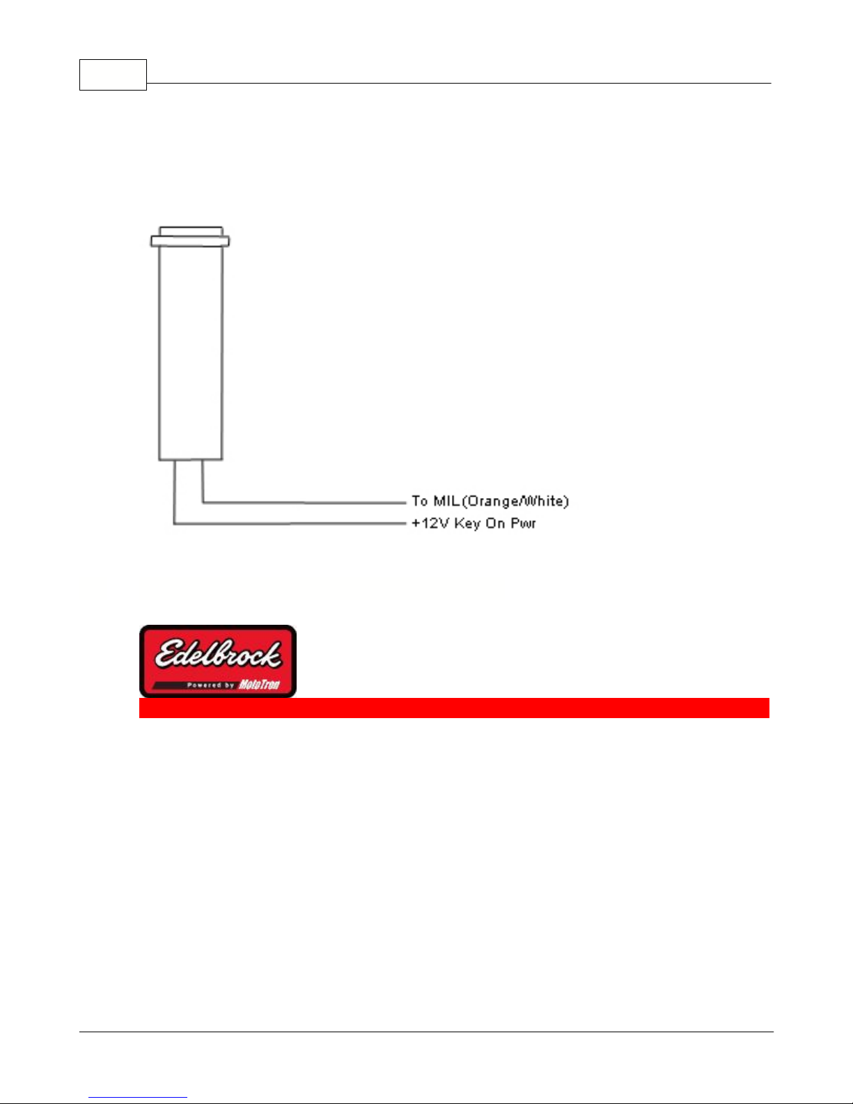
60
3.3 Installing and Configuring the Software
Installing and Configuring the
Software
Visit us at: http://www.edelbrock.com
Page 61

Installation and Setup 61
Installation and configuration of the software is much like any other Windows based
application. It uses Install Shield and will prompt you for choices during the installation.
In most cases choosing the "NEXT" button will give you the recommended default values.
Page 62

62
3.3.1 System Requirements
Visit us at: http://www.edelbrock.com
System Requirements
Listed below are minimum requirements for the software, hardware and operating
system for the Pro Tuner Laptop installed software:
Hardware:
1. Pentium Processor 500 MHz or better
2. One Serial Port and one USB port
OR
3. Two USB ports (using the optional USB to Serial Adapter)
4. 128 Mb or more of memory (RAM)
5. 250 Mb of free disk space
Operating System:
1. Microsoft Windows 2000 with all Microsoft updates and patches applied
OR
2. Microsoft Windows 2000 Professional with all Microsoft updates and patches
applied
OR
3. Microsoft Windows XP Home Edition with all Microsoft updates and patches applied
OR
4. Microsoft Windows XP Professional Edition with all Microsoft updates and patches
applied
IT IS HIGHLY RECOMMENDED THAT YOU OBTAIN/USE A LAPTOP WITH THE NEWEST
POSSIBLE MICROSOFT OPERATING SYSTEM AND THE FASTEST PROCESSOR SPEED WITH
AS MUCH RAM AS POSSIBLE. THE PERFORMANCE OF YOUR PRO-TUNER SOFTWARE WILL
BE MUCH IMPROVED WITH A HIGH PERFORMANCE PC; IN ADDITION, MICROSOFT
DISCONTINUES SUPPORT OF THE OLDER OPERATING SYSTEMS - WHICH MAY CAUSE
SOFTWARE RELATED PROBLEMS WITH THE PRO-TUNER INTERFACE. LATER MICROSOFT
Page 63

Installation and Setup 63
OPERATING SYSTEMS ALSO HAVE IMPROVED HANDLING OF PERIPHERALS, USB PORTS,
AND BETTER STABILITY THAN WIN98SE SYSTEMS.
Page 64

64
3.3.2 Installing the Software
Installing the Software
Software installation steps:
1. Insert the CD in the CD drive
2. The installer should Auto Play. Once you see the installer welcome screen, go to
step 3. Some virus protection programs do not allow Auto Play, so if that is the
case:
1. Double click on "My Computer"
2. Double click on the CD ROM drive icon
Visit us at: http://www.edelbrock.com
3. Double click on the EDELEFI_2_3_4_X.msi file on the CD ROM (the numbers
may be different, depending on version and build )
3. You will see installer start and prepare your computer for installation:
Page 65

Installation and Setup 65
4. Once the computer is ready, the installation will start:
5. Click NEXT >
Page 66

66
6. The license agreement is displayed. CAREFULLY READ THIS AGREEMENT. IT
WILL EXPLAIN YOUR RIGHTS AND LIABILITIES IN THE USE OF THIS
PRODUCT!
7. Click NEXT > once you have read and understand the license agreement
8. Choose the folder in which you want the Edelbrock Victor Pro Tuner software
installed.
IT IS HIGHLY RECOMMENDED YOU ACCEPT THE DEFAULT LOCATION
PRESENTED IN THE INSTALLER.
To accept the default, just click NEXT >
Page 67

Installation and Setup 67
9. The installer will now ask one more time to confirm the installation process. This
will allow you to cancel the installation if you wish:
Page 68

68
10.To proceed, click "Install"
11.The installer will proceed to install the necessary files on your computer ... the
status will be displayed during the install:
12.Once the install is completed, click the FINISH button and you are ready to use
your new software!
Page 69

Installation and Setup 69
Page 70

70
3.3.3 Installing the Communications Hardware
Connecting the Laptop to the Vehicle
Inventory:
1. Laptop running Windows 2000 or newer OS with at least 128 Mb of memory and a
500 MHz processor. The computer speed and memory will greatly affect the
performance of the application. Run the latest Microsoft Operating System and
most powerful PC possible to avoid windows related issues such as USB port driver
problems.
2. Computer Connection cable
Visit us at: http://www.edelbrock.com
3. USB Key (or "dongle") The key will be either a "Base" system key or a "Pro" level
key. The key is required for the software to connect to the ECU.
Connection:
Before hooking up the laptop, be sure the following conditions are met:
Page 71

Installation and Setup 71
1. The laptop is booted and ready
2. The USB Key is plugged into an available USB slot on the computer
3. The Computer Connection cable is plugged into the Interface connector on the
harness
4. The Computer Connection cable is plugged into the PC's serial port
5. The ignition key is in the ON position
Once everything is hooked up to the PC and the harness, look for an LED light (steady)
on the gray colored interface module (part of the Computer Connection cable). This
indicates a powered connection and the PC is ready to communicate. As the computer
communicates to the vehicle ECU, a few cables may have additional red and green LEDs
that will blink. This indicates data is flowing back and forth between the PC and the ECU.
Note: Avoid repeated unplugging or disconnect of the USB adapter or
serial cable. Microsoft windows will occasionally not reconnect properly. If
you have trouble reconnecting after plugging in hardware, or after
hibernation. Rebooting the machine will usually clear it up.
Page 72
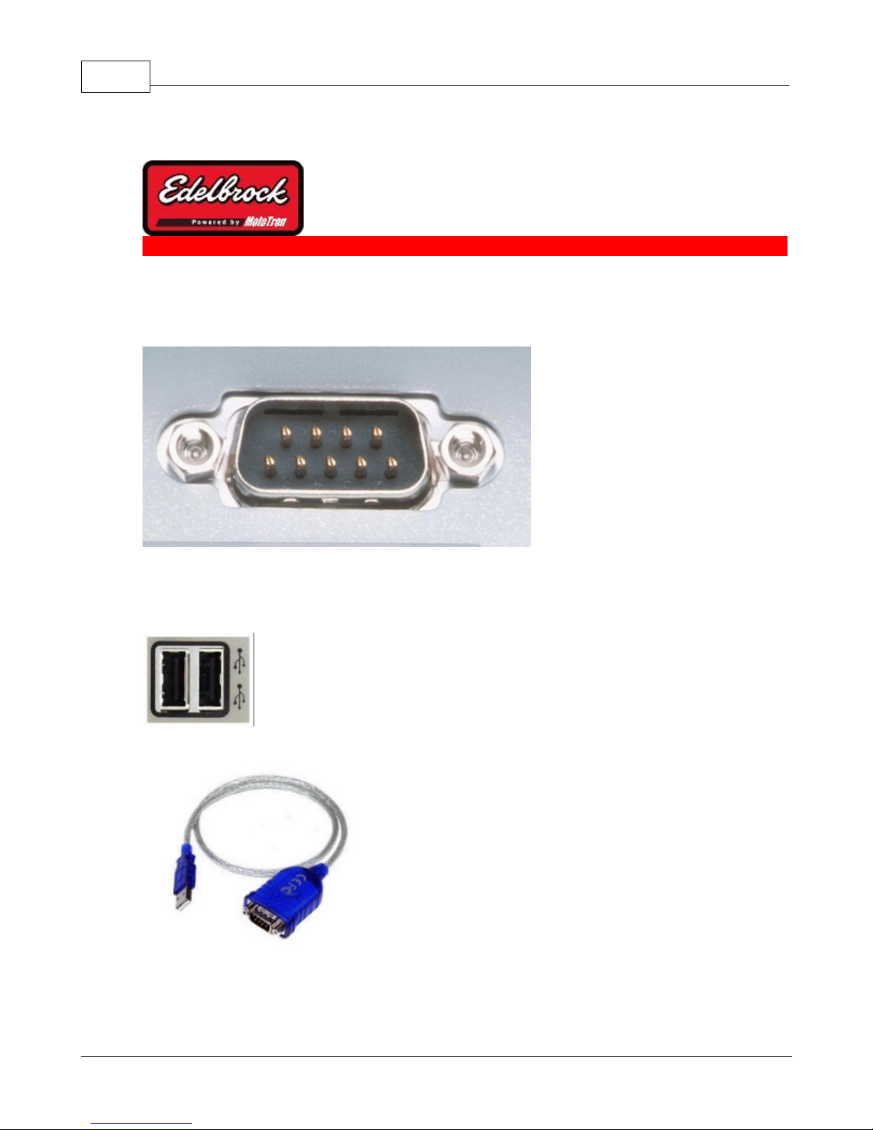
72
3.3.3.1 USB/Serial Converters
USB to Serial Converters
Some laptops may not have a serial port (pictured below)
Visit us at: http://www.edelbrock.com
Serial Port
However, you can use one of the PC's USB ports and a USB/Serial Adapter (not included)
that is readily available from many sources, including local consumer electronics stores.
USB Ports
Typical USB/Serial Adapter
Follow the Serial/USB Adapter manufacturer's instructions to install and configure the
device for your PC. Once the software has been successfully installed, and the device is
Page 73

Installation and Setup 73
plugged in, if you run the Edelbrock Pro Tuner software installation for the first time,
the connection wizard will automatically detect and configure to use the appropriate
device.
If you already have the Pro Tuner software installed, you can manually add the new
device to the list of communication ports for Pro Tuner by performing the following:
1. First, we need to know which port was configured by the adapter manufacturer for
use with that particular device. This is a function of Microsoft Windows, so we will
first RIGHT CLICK on "My Computer" and then choose "MANAGE".
Page 74
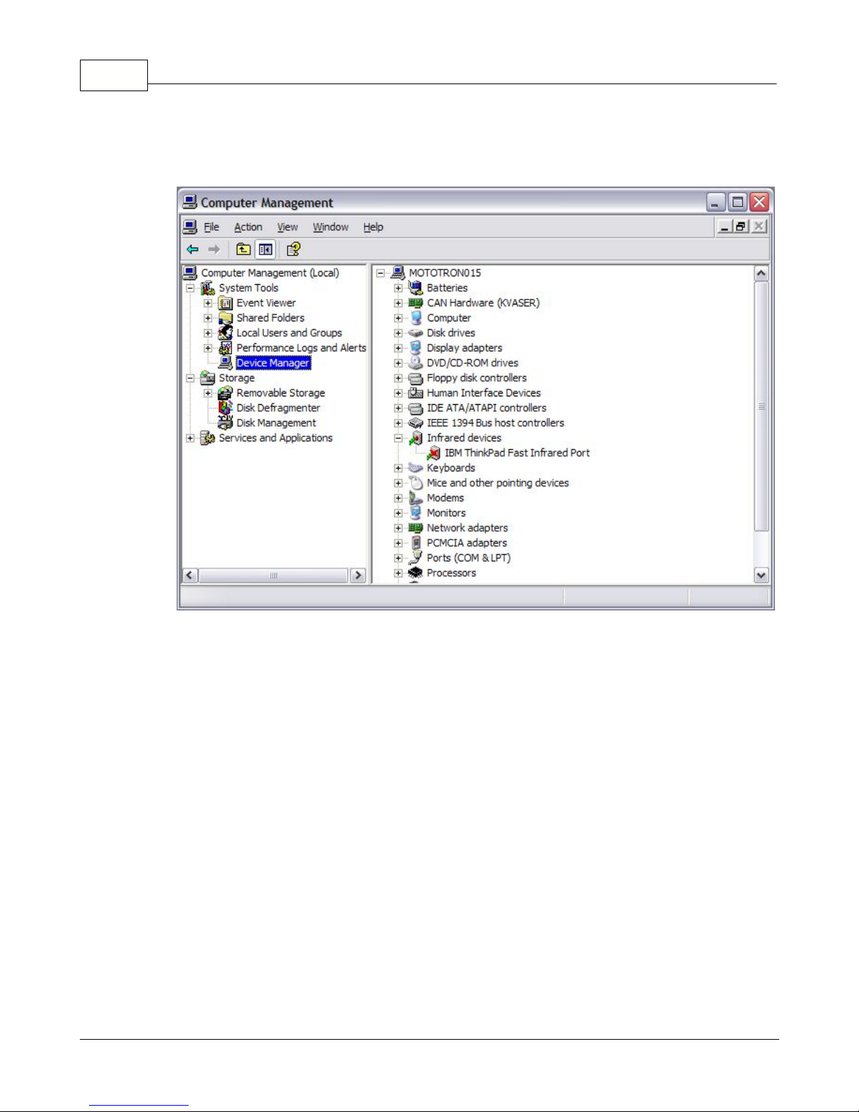
74
2. Now choose "DEVICE MANAGER" to get a list of the installed and active devices
for your PC.
3. Click on the "PORTS" Icon to expand the list of communications ports. You should
see your USB to Serial Adapter in the list of ports. Often times, it will be assigned
to COM4 if you don't have a lot of other devices attached to your PC. In this
example, we see the "Prolific USB-to-Serial Com Port" on COM8.
Page 75

Installation and Setup 75
4. Make a note of the COM port assignment and close the Computer Management
window.
5. Now, RIGHT click on the MotoServer icon (the satellite dish) in the System Tray
(lower right hand corner of your screen)
6. A menu will appear for MotoServer. Choose "Ports..."
7. A list of the configured ports will appear. To add the port that the USB/Serial
Adapter manufacturer's software configured, click on "Edit Names".
Page 76

76
8. When you click "Edit Names", you will be presented a choice of pre configured
ports. If the COM port you need is in the list, simply select that port and then click
"OK". If it does not exist, click "Add" to add your new port.
9. When you click "Add", you will be asked what kind of port is to be added. Select "
Serial" and the click "Next".
10.Type your new COM port name and number in the space provided. In this example,
we will call the port "COM8" and put "8" in the Port text box, since that's what we
noted earlier in the Device Manager.
Page 77
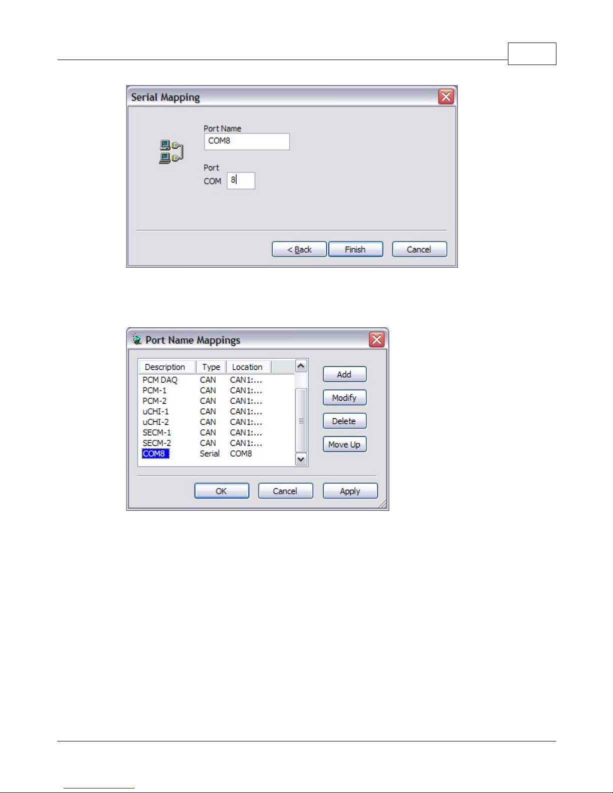
Installation and Setup 77
11.The new port name then appears in the Port Name listing.
Make sure the new port is selected and then choose "OK" (or "Apply" if you have
more ports to add).
12.You will now be back at the Port Configuration window. Choose "Add " and then
select the Type and Location with the drop down lists.
Page 78

78
Be sure the Access Level is set to "4".
13.Click "OK" and you will see the new Port Added to the Ports List.
14.From now on, the Pro Tuner system will check to see if communications cable is
plugged into any of the devices listed in the Ports Configuration List every time you
start the program. You can add a large number of pre configured ports as
necessary to support your needs.
Page 79

15.Click "OK" to complete the set up.
Installation and Setup 79
Page 80

80
3.3.4 Connecting to the Vehicle
Visit us at: http://www.edelbrock.com
Connecting to the Vehicle
Once you have successfully installed and configured your software and communications
cables, you are now ready to start communicating with the Vehicle ECU.
Steps:
1. Start the Edelbrock EFI Application by double clicking on the Icon on your desktop:
Edelbrock EFI
2. The application will start up and when it loads completely you will have a dialog
that looks like:
Page 81

Installation and Setup 81
Be sure the ignition key is in the ON position and your USB key is installed
in an available USB port on your laptop. To connect directly to the ECU, click on
"Connect directly to your Vehicle's ECU" and then click on "OK ". To go into
OFFLINE mode click "Open an existing calibration" file and the OFFLINE Control
Panel will be displayed. More information about OFFLINE can be found later on in
the HELP in the OFFLINE mode help section.
3. If this is your first time connecting to the ECU, you will be led through several
steps that determine the correct port for your software to communicate with on
your computer.
Page 82

82
Click NEXT
Click NEXT
Page 83

Installation and Setup 83
The computer has now found the proper port. Click NEXT.
The computer is now ready to attempt to "talk" to the ECU. Click NEXT.
Page 84

84
Once a connection is established successfully, click NEXT.
Click NEXT to get the final results dialog.
Page 85

Installation and Setup 85
Click FINISH.
4. The software will now connect to the ECU and bring up the DASHBOARD screen:
Page 86

86
Page 87

3.3.5 Application Settings and Preferences
Application Settings and Preferences
Use this control panel to customize the application settings to your preferences. This
control panel allows you to choose preferred units and default paths for files on your
computer.
To choose your desired units, go to "TOOLS" menu and choose "Application Settings".
You will see the following Control Panel:
Installation and Setup 87
Visit us at: http://www.edelbrock.com
Choose your desired units of measure for each category (Temperature, MAP, Pressure
(such as oil pressure, fuel pressure, etc.), Volume, and A/F ratio). Once you have chosen
your desired units, you can also set your Storage preferences or apply your choices by
choosing either the Apply button (which will simply apply the changes) or the OK button
(which will apply the changes and close the control panel). If you choose to change
Storage Settings, click on the "Storage" tab and you will then see:
Page 88

88
Navigate to the desired storage location for calibration files and click "Apply" or "OK".
You will then be advised with the following:
Close all application windows and then restart the application. This will apply your new
choices to the gauges, tables, MAP's and controls.
Page 89

4 Basic Tuning with the Pro Tuner System
Visit us at: http://www.edelbrock.com
Basic Tuning with the Pro Tuner
Installation and Setup 89
System
The Pro Tuner System is extremely powerful; however, a significant effort has been made
to simplify the way information is presented to you to allow you to concentrate on the
reason you bought the system - mainly reliability, horsepower, and drivability.
It is very important that you understand the basic principles of the system so that you
can effectively use the PC software to configure and run your combination.
Page 90
90
4.1 Setup Wizard
Initial Setup Wizard with Laptop
Connected
The Setup Wizard functionality is used to make fundamental changes to your system
configuration, such as new fuel injectors, different distributor or coil, new sensors, etc. It
is also a good way to setup a "bare" system for first time use.
1. To start the wizard, go to TOOLS in the top menu of the main application.
2. Choose "Setup Wizard"
3. The wizard will start up and you will be asked to make various choices to set up
your system. If this is NOT your first time into the wizard, it will go to the last
thing you successfully executed (a BOOKMARK). At that point, you can go directly
to the area that you need to make changes to without stepping through the rest of
the wizard.
4. Assuming this is the first time through, you will first see this screen:
Visit us at: http://www.edelbrock.com
Page 91
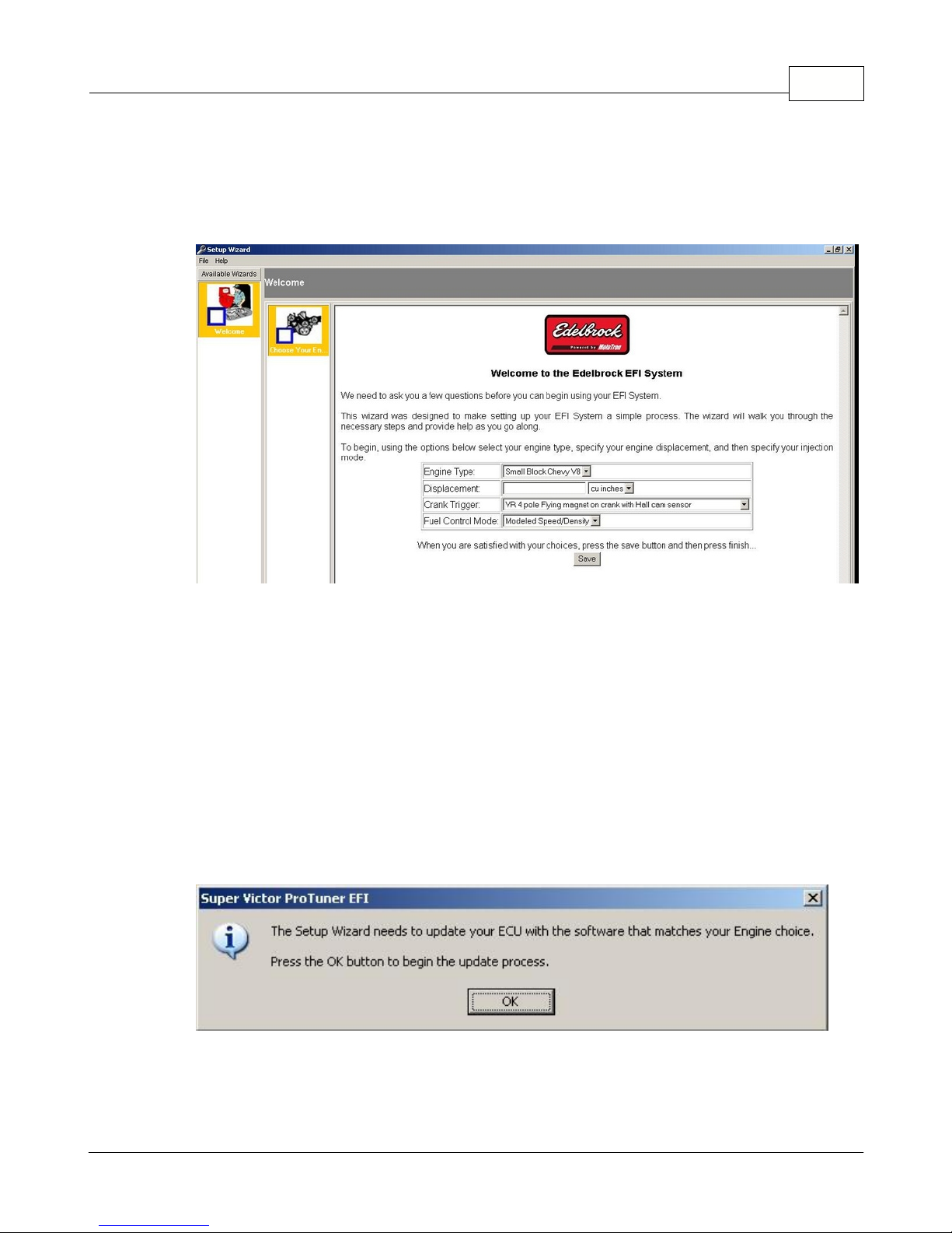
Basic Tuning with the Pro Tuner System 91
5. Click NEXT and watch the status bar at the bottom of the screen as it establishes a
new connection to the ECU and configures it for programming.
6. The next screen will show you the Engine Setup wizard to help you configure your
basic engine parameters:
7. Choose your basic engine type and then enter it's displacement in cubic
inches (default) or liters (chosen via the drop down)
8. Choose the type of crank trigger you are using in your kit
9. Select your fueling control method: Speed/Density or Alpha-N(Speed/
Throttle). Note: You may also choose MAP-N (Speed/Pressure), but you must
select Alpha-N and the system will then program the ECU and give you the MAP-N
option in the following screen. MAP-N uses similar lookup tables and trim tables as
Alpha-N.
10.Click "SAVE" to commit your changes.
11.The "FINISH" button will then replace the "NEXT" button. Click "FINISH" if
you are satisfied with your choices.
12.The ECU will now be reprogrammed with your "base" system setup. Please
click OK to continue.
13.The wizard will prepare the ECU:
Page 92

92
14.The wizard will then program the ECU. Please wait for it to finish completely:
15.When programming is completed, you will be presented with the next wizard
section to configure/choose your sensors. The WELCOME section will show a
CHECK MARK to show that it has been completed:
Page 93
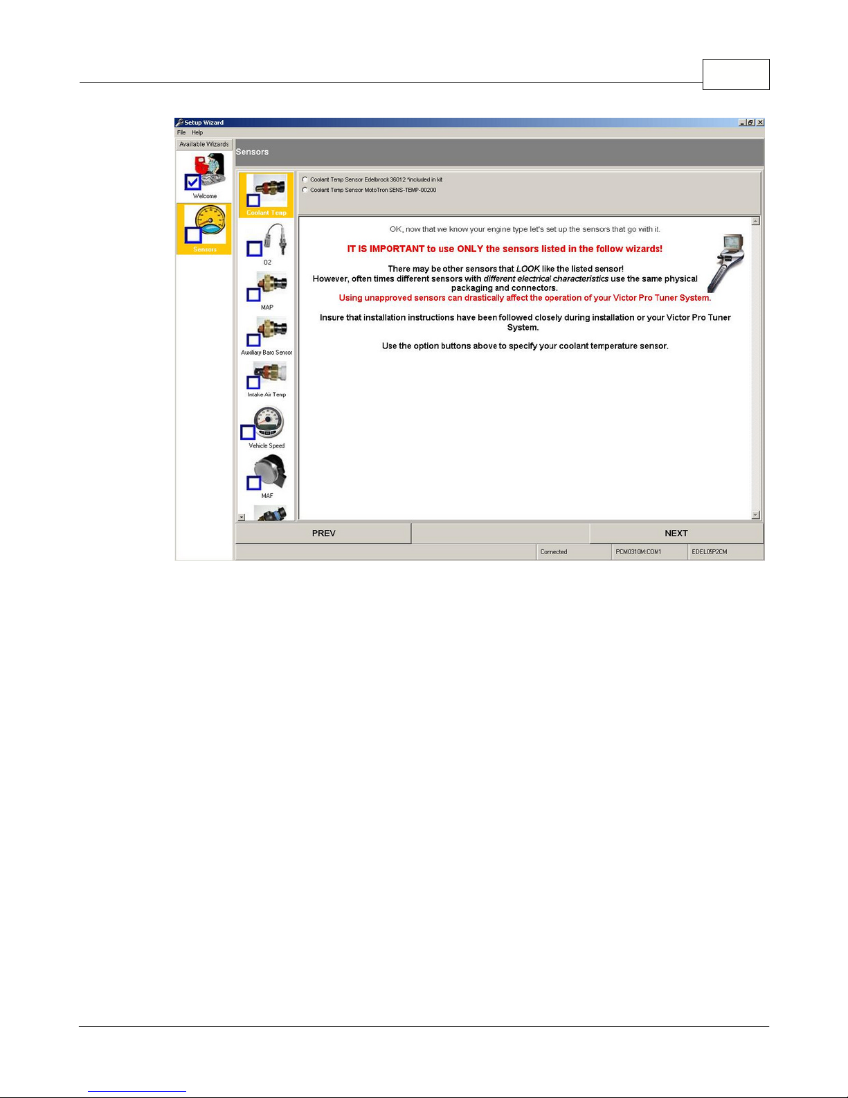
Basic Tuning with the Pro Tuner System 93
16.Continue to progress through the various section and choices, using the NEXT
buttons and FINISH buttons (as they are presented) to configure your system.
17.Once you have finished all the sections, the wizard will save your changes/choices
and reprogram the ECU a final time before exiting.
Note:
Only for users who select the MAP-N tuning strategy from the Wizard setup:
Once the Wizard programming steps are completed, you must load the supplied MAP-N file into your ECU. To do this,
go to the file menu and select "Load Calibration from Disk". Navigate to the installed calibrations folder located at
/Program Files/Edelbrock/EFI/ECUFiles/Cals. The MAP-N calibration file for the P/N 3670 Kit is identified as
EDEL07E1EB_V004XDC_MAPN.hcal. The MAP-N calibration for the P/N 3690 Kit is identified as
EDEL07P1EB_V004XDC_MAPN.hcal. Choose the appropriate calibration for your kit to load into the ECU.
Page 94

94
4.1.1 Scaling Setup - Custom Load and RPM Axis
Scaling Setup - Custom Load and
RPM Axis
If desired, the setup wizard can be used to define custom load and RPM axis. These 2-D
tables define the breakpoints of any Pro-Tuner tables that vary as a function of engine
load or speed. The breakpoints do not have to be linear or evenly spaced. You can
define more closely spaced breakpoints at lower engines speeds and wider spaced ones
at higher speeds where the engine will likely spend less time. To customize your load or
RPM axis, begin by selecting "Custom" from the following menu selections in the wizard.
Visit us at: http://www.edelbrock.com
Custom Scaling selection for load ordinate:
Custom Scaling selection for RPM ordinate:
Page 95
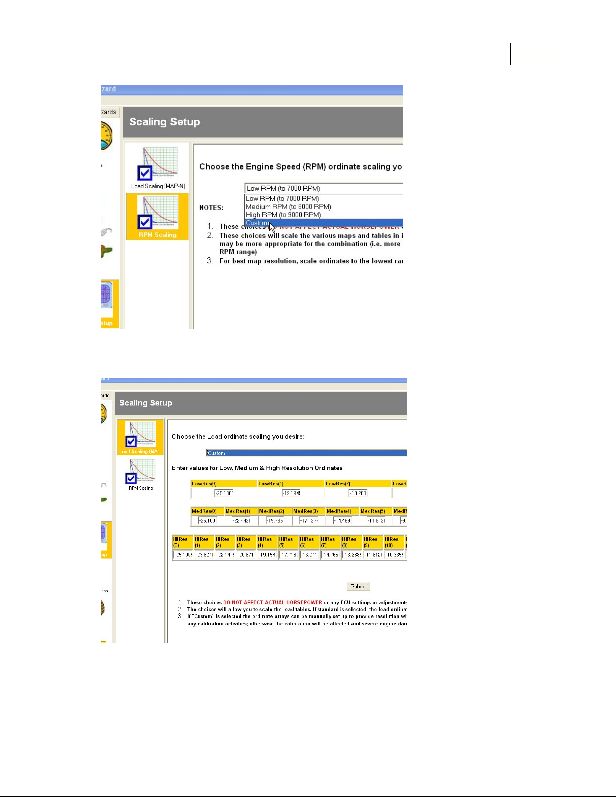
Basic Tuning with the Pro Tuner System 95
Custom tables for load ordinate:
Custom tables for RPM ordinate:
Page 96

96
Enter your desired load or RPM axis breakpoints in the above tables. Use the tab key to
move from one location to another. When finished hit the "Submit" button. Three
different resolution levels must be defined. Depending on the particular table in the
software, the resolution can be high, medium or low. Examples of high resolution
breakpoints are the base fuel and spark maps.
4.2 Screens, Indicators and Tools
Screens, Indicators and Tools
In this section, the various graphical screens, indicators and tools will be discussed in
detail. In general, there are some consistent concepts in the way that the software
presents information and allows you to manipulate various parameters. The application
has a main or "home" view that includes a window that allows you to see various gauges
and displays with a simple click of a tab. This is referred to as the DASHBOARD.
Visit us at: http://www.edelbrock.com
Page 97

Basic Tuning with the Pro Tuner System 97
By clicking on the TABS along the top of the screen, you can see several other functions
available for quick reference.
At the bottom of the main screen, you will see a Status Bar. Watch this area for alerts,
current activity, Faults, and user information.
AT ANY TIME YOU CAN HIT THE 'F1" Key and activate help for the
function that you are working with!
By holding your mouse pointer over a gauge, text box, or indicator, often times you will
get a "Tool Tip Help" bubble that gives you a brief description of what you are looking
Page 98

98
at.
Several specialized tools are available as Menu Options and can be activated by selecting
them from the drop down menu bar at the top of the window.
Page 99

4.2.1 Dashboard
Dashboard TAB
Basic Tuning with the Pro Tuner System 99
Visit us at: http://www.edelbrock.com
The DASHBOARD Tab is considered the "HOME" screen. From here you can monitor
most critical engine functions quickly at a glance.
The function of most of the gauges are self-explanatory, however there are a couple of
Page 100

100
important point to note:
Certain gauges will not appear in all configurations. For example, the optional oil
•
and fuel pressure gauges may or may not be on the screen, depending on your
configuration (set in the Setup Wizard).
The scaling of gauges (including the Tach) will adjust based on your Setup
•
Wizard choices.
The scaling and labeling of the gauges and some map ordinates will change based
•
on your USER PREFERENCES picked from the APPLICATION SETTINGS
portion of the menu bar.
 Loading...