

Page 1
PN 72700
12-Volt 10-lb./15-lb. Nitrous Bottle Heater
Installation Instructions
Please read these instructions carefully before you begin installation.
1. Secure the Edelbrock bottle heater around the bottle using the Velcro straps. Mount the heater
around the bottom section in a manner so that the end gap is at the top of the mounted bottle,
making sure that the electrical connections are free. Do not cover the bottle label.
2. Place thermostat assembly under one of the velcro straps. Position it between the bottl e surface
3. Mount the relay assembly in an area close to the bottle in a location that will be as moisture free as
4. Route the red wire from the bottle heater to the blue wire on the relay.
5. Connect the black wire from the heater to a chassis ground. Remember to leave enough wir e for
6. Connect one(1) wire from the thermostat to the black wire on the relay assembly.
7. Connect the other wire on the thermostat to a good ch assis ground. Remember to leave enough
8. Route the red wire on the relay harness, (that i ncludes the inline fuse) directly to the positive side
9. Mount the bottle heater on-off toggle switch in the passenger compartment. Place it in a
Important Note: Please ensure that the bottle heater is installed snugly with no
ripples. The bottle heater must completely contact the bottle
and the strap, ensuring the thermostat is in full contact with the bottle. This is your bottle
temperature reference signal and it must be installed correctly or damage may occur.
possible. Keep the relay assembly away from high traffic areas.
the relay.
bottle removal and replacement before and after filling.
wire for bottle heater movement during bottle removal and replacement before and after filling.
battery post or starter solenoid post that the battery cable attaches to. This is done to ensure that
the maximum current draw is done through the relay and not the switch. Failure to attach this wire
directly to either of these two locations can result in possible electrical failure. Use appropriate
connector to splice into power wire (minimum 12-gauge wire).
convenient and visible location. Ensure that during the installation, the lighted portion of the switch
is working and easily visible.
Features:
Durable, Long-Lasting Heating Element
Velcro® Straps for Easy Installation
Dual Thermostat Cartridges for Reliability
All Electrical Hardware Included
.
Hard or blunt impacts can damage
1
Page 2
10. Connect terminal #1 from the toggle switch to an “ignition-switched” +12 volt source. We
recommend that you connect this wire to the switched-on power of the vehicle’s nitrous system
arming switch. This ensures that the heater can only be activated when the nitrous system is
armed.
11. Connect terminal #2 from the toggle switch to the white wire on the relay.
12. Connect terminal #3 to a good chassis ground.
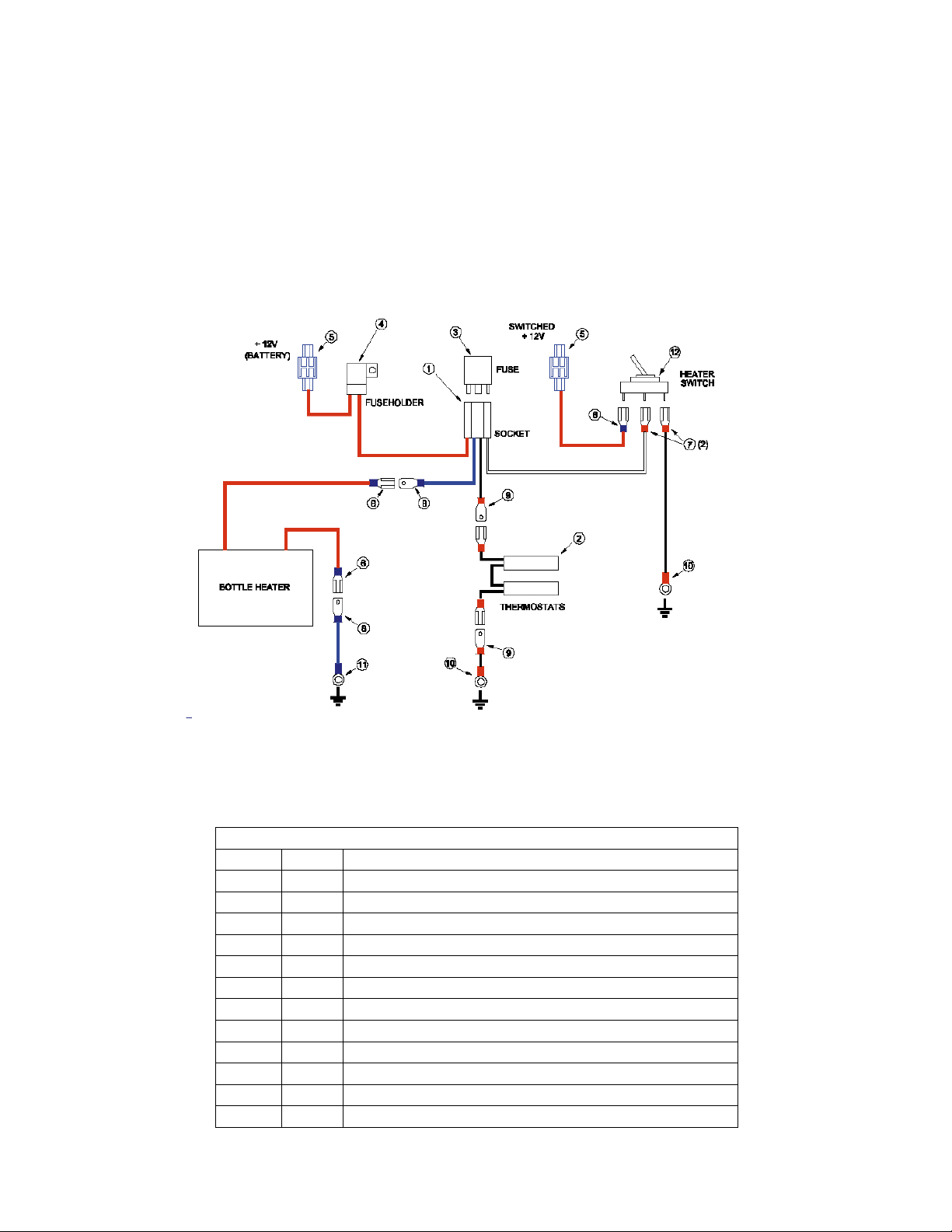
Wiring Diagram
Hardware Includes:
Item Qty. Description
1 1 Nitrous Relay Receptacle
2 1 Thermostat Assembly
3 1 Relay, SPDT, with Diode
4 1 Fuse, ATO, 25 Amp
5 2 Crimp-on Splice Connector
6 3 Crimp-on Disconnect Terminal, Female, Blue
7 2 Crimp-on Disconnect Terminal, Female, Red
8 2 Crimp-on Disconnect Terminal, Male, Blue
9 2 Crimp-on Disconnect Terminal, Male, Red
10 2 Crimp-on Ring Terminal, Red
11 1 Crimp-on Ring Terminal, Blue
12 1 Switch, Toggle, Power, Lighted
2
Page 3

To Test Bottle Heater for Correct Operation:
This Edelbrock heater should never be used with the thermostats installed. The thermostats must
always be in contact with the surface of the bottle in order for the thermostats to properly sense the
bottle temperature. The thermostats have a cut-in and cut-out setting at 85º F
+/- 5º F. Failure to follow this important warning will result in the temperature of the bottle to rise to
unsafe temperatures and the pressure within the bottle to rise to levels that could lead the bottle
Pressure Relief Device to rupture, causing the bottle contents to empty.
1. Turn ignition key to the “run” position.
2. Turn the vehicle’s nitrous system toggle switch to the “on” position.
3. Turn the bottle heater toggle switch to the “on” position.
4. A “click” should be heard from the heater’s relay when first activated as long as the thermostats are
below 85º F.
5. Heater should now start to warm up. It may take a few seconds for the heater to heat up to correct
operating temperature.
6. When bottle temperature reaches near 85-90º F, the thermostats will cut off the ground to the relay,
de-activating the heater. When temperature drops below 85º F, the relay will be grounded through
the thermostats, re-activating the heater.
Troubleshooting
Heater Takes a Long Time to Heat Up.
1. Be sure thermostat touches bottle and is positioned between end gap of heater. Heater wil l
IMPORTANT WARNING
not operate correctly if thermostat comes in contact or is too close to the heater element
itself.
2. Inspect all ground connections. Check for shorts.
Bottle Heater Does Not Get Hot.
1. Ensure that there is power through the relay. Temporarily place black wire from relay to
ground. This will bypass the thermostat and will activate the rela y to supply power to the
heater. If this does not activate the heater, check below items. Ensure all electrical
connections are made as shown in diagram.
2. Check for bad inline fuse. Replace with a 25 amp. fuse.
3. Check toggle switch.
4. Check all wires for shorts.
5. Check all ground connections.
6. Check thermostat. When temperatures are below 85° F, there will be continuity on the
thermostat wires. When there is no continuity below 85° F, replace thermostat.
3
Page 4

Caution
1. The bottle heater surface can achieve temperatures in excess of 400 degrees. Do not attempt to
handle, adjust, or remove from the bottle while the heater is in operation.
2. Do not touch heater surface while in operation. Severe burns to the skin can result.
3. Do not rest or lie heating element against flammable or temperature sensitive materials, objects,
paints, or coatings as they could be caused to ignite due to the excessively high temperatures.
4. Do not operate this heater unless installed properly and securely attached to a nitrous cylin der as
damage to the heater could result.
5. Do not operate this heater when attached to a nitrous cylinder that has a closed cylinder valve as
this could cause high in-cylinder pressures and cause the pressure relief device t o open an d release
the bottle’s contents.
6. Do not operate this heater for extended periods of time.
7. Do not expose heater to an open flame as this can cause the heating element to fail.
8. Do not rest the heating element against a vehicle’s structural member of any hard surface while
attached to the bottle as this could damage the internal element windings within the heater.
9. Do not attempt to remove the bottle from the bottle moun ting in the vehicle without first removing
the bottle heater. Contact with the bottle mounting brackets could cause damage to the internal
wiring within the heater.
Always refer to your Nitrous System Owner’s Manual or Instructions for safety precautions when performing
any service on your Nitrous System.
Edelbrock Corporation shall not be liable for any and all consequential damages occasioned by
the breach of any written or implied warranty pertaining to this sale in excess of the purchase
price of the product sold.
Edelbrock Corporation
2700 California Street
Torrance, CA 90503
Toll-Free Tech Line: 1-800-416-8628, 7 am - 5 pm, Monday-Friday, PST
E-Mail: edelbrock@edelbrock.com
2000 Edelbrock Corporation Rev. 8/00
4
 Loading...