

Page 1
©2002 Edelbrock Corporation
Rev. 10/02
Brochure No. 63-0126
Catalog #70206
Page 1 of 4
150HP Upgrade System
for the 70205 80HP LT-1 Nitrous System
Catalog #70206
INSTALLATION INSTRUCTIONS
Please study all instructions carefully before you install your new 150HP Upgrade System. If you have any questions or problems,
please call our Technical Hotline at: 1-800-416-8628, 7:00 a.m. to 5:00 p.m., Monday through Friday, Pacific Standard Time or
e-mail us at edelbrock@edelbrock.com.
Jet Map Information: Edelbrock engineers have conducted extensive dyno testing with the Edelbrock LT-1 Performer EFI Nitrous
System to ensure the horsepower increase is as intended. On a typically stock LT-1 engine, you can expect the following approximate
power gain:
Nitrous/Fuel Jetting
Approx.
HP Gains Final Air/Fuel Ratio
.068 .042 150 13.5/1
The dyno tests were conducted at Edelbrock using a stock LT-1 engine. These tests were conducted with 950 psi nitrous bottle
pressure.
INSTALLATION INSTRUCTIONS
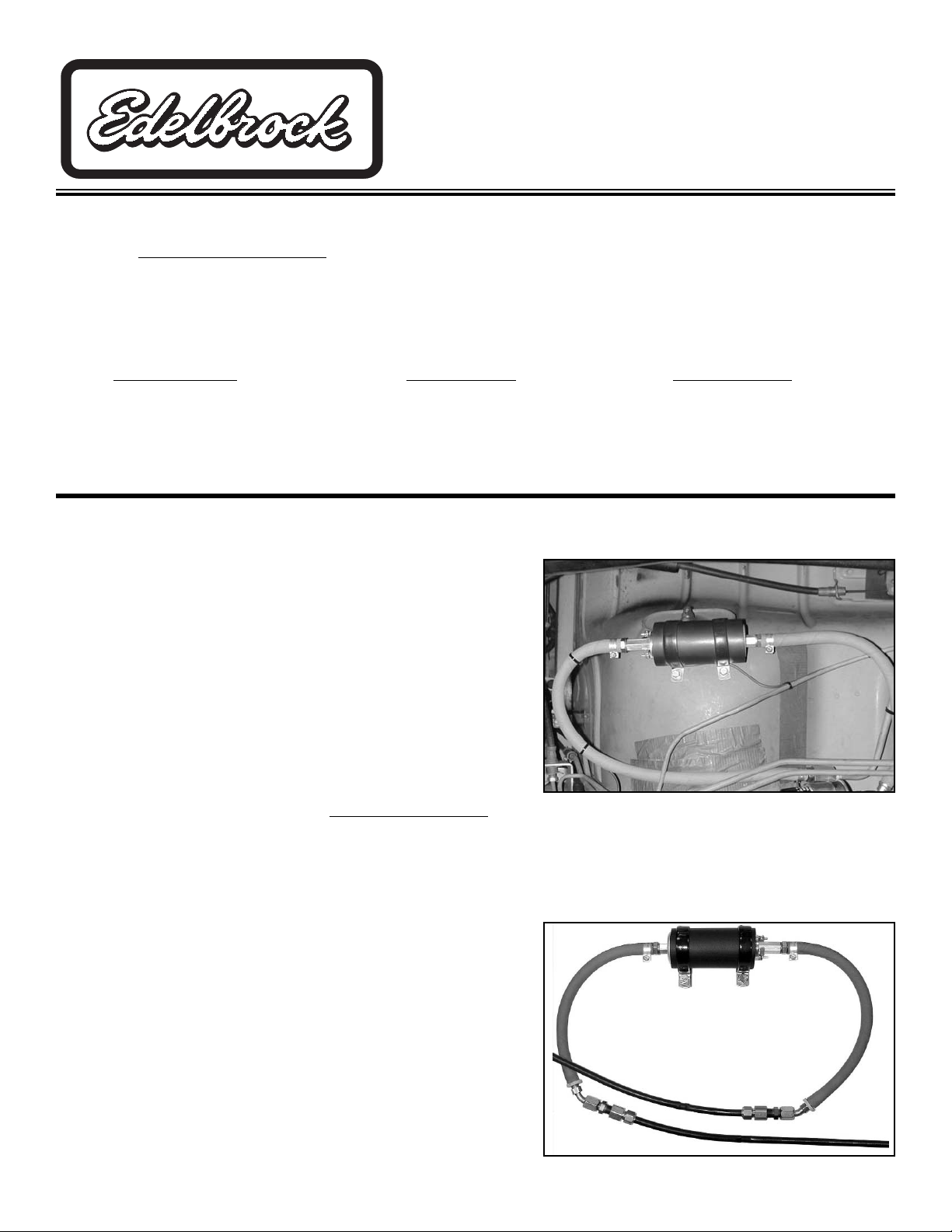
Fuel Pump Installation (Camaro, Firebird)
Warning: Before performing any of these steps, relieve the pressure in the fuel system.
1. Locate the fuel filter on the under-carriage of the car. Disconnect the
hard fuel line from the filter.
2. Install the male O-Ring to -6AN male adapter fitting into the outlet of
the fuel filter.
3. Mount the fuel pump to the under-carriage of the vehicle. Cut the
supplied fuel line to size as pictured.
4. Install the hose fittings and tighten all hoses down with the supplied
hose clamps.
5. Install the female O-Ring to -6AN male adapter to the end of the steel
fuel line. Secure fitting to hose with supplied hose clamp and connect
hard fuel line to this fitting. Check the fuel system for leaks by turning
the ignition key to the “On” position. Do not start the engine
. Inspect all fittings and lines for leaks. Also check wires from
time to time for damage or leaks.
Fuel Pump Installation (Impala)
Warning: Before performing any of these steps, relieve the pressure in the fuel system.
1. Locate the fuel lines under the vehicle. These should be 2 black plastic
lines located on the driver’s side of the vehicle by the frame rails.
Determine which line is the main feed line by following them back to
the fuel filter.
2. Determine the mounting location of the fuel pump and mount the
pump. Be sure the pump will be mounted above the lowest parts of
the car and out of danger from road debris. The pump must be
mounted between the fuel filter and engine.
3. Be sure where you decide to cut the line is close to the booster pump.
Cut the plastic fuel line using a sharp razor blade or other similar
cutting tool.
®
Page 2
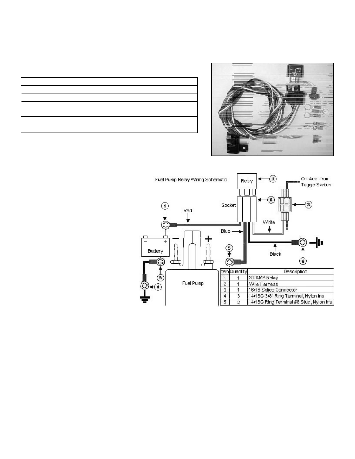
Fuel Booster Pump Electrical Components Bill of Materials
Item # Quantity Description
1 1 ea. 30 amp relay
2 1 ea. Wire harness with integral relay/fuse holder
3 1 ea. 16/18g splice connector
4 1 ea. 14/16g 3/8” ring terminal, Nylon insulated
5 1 ea. 14/16g ring terminal #8 stud, Nylon insulated
6 1 ea. 15 amp ATO blade fuse
©2002 Edelbrock Corporation
Rev. 10/02
Brochure No. 63-0126
Catalog #70206
Page 2 of 4
Fuel Booster Pump Electrical System Installation Procedures
1. Determine the location of the Fuel
Booster Relay and Fuse Holder Wire
Harness. Most common installations
locate these components inside the
driver’s compartment and close to the
fuse panel under the dash. You can also
mount the relay and fuse holder and
harness close to the battery. However,
these connectors are water-resistant, not
water-proof, so care is required when
mounting this assembly under the hood
of your vehicle.
2. The wire harness attached to the relay
and fuse holder includes 8 feet of colorcoded wires to make the electrical
system installation as easy as possible.
We recommend that you do not cut any
lengths of wires from the wire harness or complete the wiring of the fuel booster pump until all of the mechanical components
are securely mounted in their permanent locations.
3. Use the Fuel Pump Relay Wiring Schematic located above along with the Origin and Destination Map on next page to determine
the proper routing for the wires and their locations. Take caution as to not interfere with operating linkages, heat sources,
brackets, etc. Pay particular attention to sharp edges along the route of your wire harness as they can chafe the wire and cause
your system to fail.
4. Once all components have been securely mounted, decide the location of the relay and fuse holder. Secure them with fasteners
(not included with kit) such as sheet metal screws, nuts and bolts, etc. Allow for some slack in the red wire that connects the
relay and fuse holder together.
5. When mounting your relay and fuse holder, make sure the mounting surface is strong enough to support servicing the relay and
fuse. Also, ensure you allow for some slack in the wire that joins the fuse holder to the relay mount. This will avoid any potential
loss of power due to stress on the wire harness. Be sure to cover the fuse with the fuse mount housing.
4. Install the supplied compression fitting adapters to the cut plastic fuel line. Using the supplied fuel line, cut lengths that will
reach from the booster pump to the hose barbs on the compression fittings.
5. Install cut fuel lines and secure using the supplied hose clamps.
6. Check the fuel system for leaks by turning the key to the “On” position. Do not start the engine
. Inspect all fittings and lines
for leaks. Also check wires from time to time for damage or leaks.
Page 3

©2002 Edelbrock Corporation
Rev. 10/02
Brochure No. 63-0126
Catalog #70206
Page 3 of 4
Knock Sensor By-Pass Relay Installation
1. Determine the location of the Knock Sensor By-Pass Relay. This should be as close to the ECM as possible. Since the connectors
are water-resistant, not waterproof, mount the relay in a location with minimal chance of exposure to water.
2. The wire harness attached to the relay includes 4 feet of color-coded wires to make the electrical system installation as easy as
possible. We recommend that you do not cut any lengths of wires from the wire harness or complete the wiring of the nitrous
system until all of the mechanical components are securely mounted in their permanent locations. Do not exceed the 4 feet of
wire to the ECM and the knock sensor, this could send a faulty signal and the system would not work at optimal power. You can
extend the white and black wires beyond the 4 feet if necessary.
3. Once all of the system components have been mounted, route the un-cut wires from the harness to each location allowing
enough wire length on each circuit to not interfere with operating linkages, heat sources, brackets, etc. Pay particular attention
to sharp edges along the route of your wire harness as they can chafe the wires and cause your system to fail.
4. After you have accounted for the routing of your wires, follow the Knock Sensor By-Pass Relay Wiring Schematic above and use
the Wire Schematic Origin and Destination Map below as a guide for which electrical connectors are used in each circuit. Note
that the one wire from the ECM to the Knock Sensor needs to be cut and intercepted with the relay. This wire on 1994-1997
Camaros, Firebirds, and Impalas is located on the BLUE terminal in pin location #22. It is a blue wire. On 1993 Camaros and
Firebirds, this wire in located on the GREEN ECM connector C terminal in pin location C8. It is a dark blue wire. Try to keep the
Knock Sensor By-Pass Relay as close to this wire as possible.
5. Once you have decided the location of the relay, secure them with fasteners (not included with kit) such as sheet metal screws,
nuts and bolts, etc.
Wire Color System Origin Destination Terminal Used
Red Main Booster Relay Harness Bat. Volt. Signal 3/8” Ring
Pump Bat. Volt.
Blue Fuel Pump Power Relay Harness Fuel Booster Pump #8 Ring
Black Fuel Pump Ground Fuel Booster Pump Chassis Ground #8 Ring / 3/8” Ring
White Relay Power Relay Harness Arming Switch Splice Conn.
Black Relay Ground Relay Narness Chassis Ground 3/8” Ring
Knock Sensor By-Pass Relay Components Bill of Material
Page 4

©2002 Edelbrock Corporation
Rev. 10/02
Brochure No. 63-0126
Catalog #70206
Page 4 of 4
Wire System Origin Destination Terminal
Red K.S. By-Pass Output of ECM Relay Harness Butt Conn.
Blue K.S. By-Pass Relay Harness Knock Sensor Butt Conn.
Black Sensor Ground Relay Harness Non-Grounded Splice Conn.
Side of Microswitch
White Relay Ground Relay Harness Arming Switch Splice Conn.
Edelbrock Corporation
2700 California Street
Torrance, CA 90503
Tech Line: (800) 416-8628
Tech Fax: (310) 972-2730
Tech E-Mail: edelbrock@edelbrock.com
 Loading...