

Page 1
©
2007 Edelbrock Corporation
Brochure No. 63-641580
Catalog #641580, 541583, 641590, & 641593
Rev. 10/07 - AJ/mc
Page 1 of 4
RUSSELL COMPLETE FUEL SYSTEM KIT
FOR CARBURETED VEHICLES
Catalog #641580 & #641583 for Edelbrock Thunder Series
AVS Carburetors
Catalog #641590 & #641593 for Holley or BG Demon Carburetors
INSTALLATION INSTRUCTIONS
Please study these instructions carefully before installing your new complete fuel system kit. If you have any questions, please call
our Technical Hotline at: 1-800-416-8628, 7:00 am to 5:00 pm, Monday - Friday, Pacific Standard Time or e-mail us at
Edelbrock@Edelbrock.com.
❑ 1 Edelbrock Fuel Pump #1791
❑ 1 Russell 8” 60-micron ProFilter with clamp
❑ 1 Edelbrock Electric Fuel Pump Relay Kit #1795
❑ 1 Russell Fuel Feed Line Kit (641580 / 641583
kits include 3” filter)
❑ 2 Russell Carburetor Adapter Fittings (641590 /
641593 kits only)
❑ 2 Russell adapter fittings for fuel pump (3/8” x -6
AN adapter)
❑ 3 Russell straight hose ends
❑ 1 Russell 90° hose ends
❑ 1 Russell 45° hose end
TOOLS &
SUPPLIES RECOMMENDED
❑ Basic hand tools ❑ AN Wrenches
❑ Miscellaneous hardware for mounting components ❑ Pipe thread sealant
❑ Drill motor & bits ❑ Multimeter or test light
❑ Wire crimpers or soldering equipment ❑ Wire strippers
❑ Extra wire (Red & Black, 12 gauge & 18 gauge) ❑ Wire terminals & connectors
❑ 10A inline fuse
❑ 1 Russell -6 Tube Seal hose clamp with cover
❑ 20 ft. Russell -6 hose
❑ 10 Russell -6 cushion clamps
❑ 12 Cable ties
❑ 1 Edelbrock fuel pump block-off plate with
gaskets & hardware for small-block Chevrolet
❑ 1 Edelbrock fuel pump block-off plate with
gaskets & hardware for big-block Chevrolet &
Ford/Chrysler/AMC engines
❑ 10 ft. Russell 3/16” Wrap-It wire protective sleeve
❑ 10 ft. Russell 5/16” Wrap-It wire protective sleeve
KIT CONTENTS
WARNING!!!
Gasoline and gasoline fumes are extremely flammable. Work in a well-ventilated area away from open flames,
sparks, or other sources of ignition. Try to contain gasoline when connections are loosened, and clean up any
spills immediately. Failure to do so can result in a fire or explosion.
IMPORTANT NOTE:
Proper installation is the responsibility of the installer. Improper installation will void warranty and may result in
poor performance and engine or vehicle damage.
Page 2
©
2007 Edelbrock Corporation
Brochure No. 63-641580
Catalog #641580, 541583, 641590, & 641593
Rev. 10/07 - AJ/mc
Page 2 of 4
1. DISCONNECT BATTERY ground(-) to prevent short that
could damage electrical components or ignite gasoline
or gasoline fumes. Stainless steel braid on hose
included in #641580 and #641590 kit will conduct
electricity.
2. Allow engine to cool. Relieve any residual fuel system
pressure.
3. Remove all fuel system components and plumbing
between fuel tank outlet and carburetor inlet, noting
routing of hoses and lines. Cap off fuel tank outlet.
4. If needed, install appropriate supplied block-off plate
onto fuel pump mounting boss on engine block using
supplied gasket and hardware.
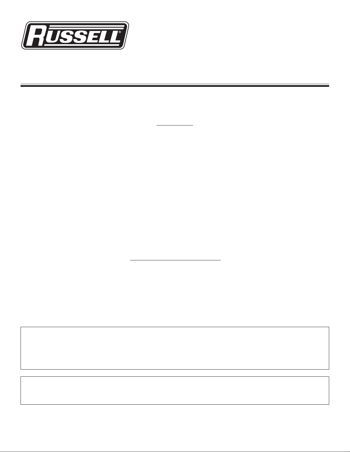
FUEL PUMP & 8-1/4” PROFILTER
5. Install supplied Russell adapter fittings into inlet and
outlet of Edelbrock electric fuel pump, using pipe thread
sealant
(See Fig. 1)
.
6. Create mounting location for fuel pump and large
Russell filter. Filter goes between tank and pump.
Pump should be as close to fuel tank as possible, and as
low as possible without being exposed to exhaust heat,
suspension or driveline movement, or road hazards.
Use fully-clamped pump mounting bracket as template
for drilling mounting holes. NOTE: fabrication of an
additional mounting bracket may be required
(See Fig. 1)
.
7. Mount fuel pump in desired location. Mount filter with
supplied clamp
(See Fig. 1)
.
INSTALLATION PROCEDURE
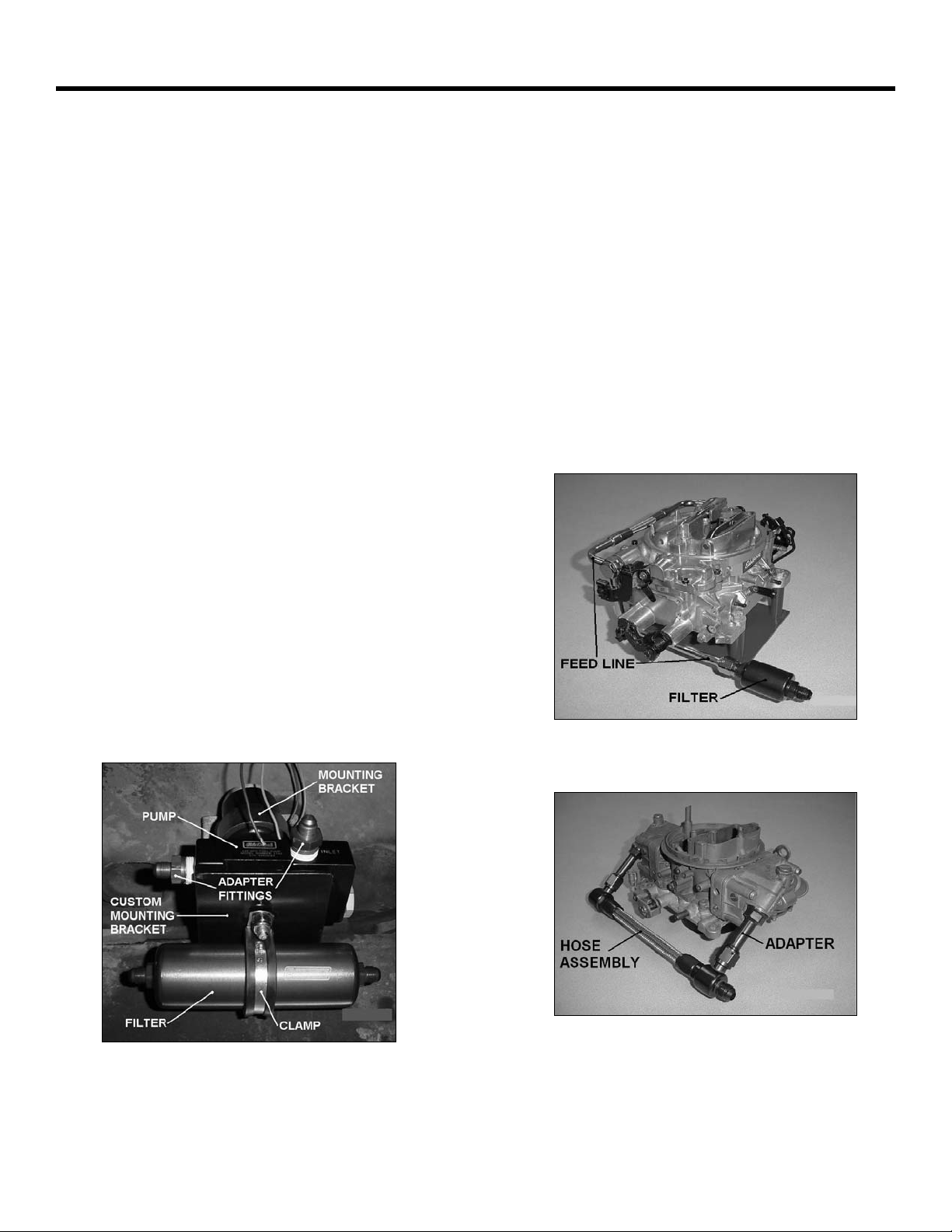
CARBURETOR FEED LINE
641580/641583 Edelbrock Thunder Series AVS:
8a. Install supplied Russell carburetor fuel feed line using
supplied banjo bolts and washers
(See Fig. 2)
.
8b. Install small Edelbrock filter onto feed line inlet
(See Fig. 2)
.
NOTE: An additional Russell adapter fitting or hose
assembly may be required to relocate filter if application
has inadequate clearance.
641590/641593 Holley/Demon:
9. Select appropriate carb bowl inlet adapters; lube threads
and install using supplied shim sealing washers. Install
lower flex hose assembly onto adapters
(See Fig. 3)
.
Fig. 1
Fig. 2
Fig. 3
Page 3

©
2007 Edelbrock Corporation
Brochure No. 63-641580
Catalog #641580, 541583, 641590, & 641593
Rev. 10/07 - AJ/mc
Page 3 of 4
HOSE ASSEMBLY
10. Select appropriate Russell hose ends for each section
and temporarily screw them onto their respective
adapter fittings to determine hose length. Use supplied
Russell hose clamp with cosmetic socket cover to
attach hose to barbed hard line coming off fuel tank.
NOTE: Route hoses away from exhaust system and
hazards such as driveshaft, exposed electrical
connections (641580/641590 kit), and suspension
pinch points. Do not expose hose to road hazards by
routing below framerails. Also, some motorsports
sanctioning bodies have regulations on fuel hose
routing. Consult appropriate rulebook if vehicle will be
used in competition.
11. Mark supplied Russell hose at point to cut and wrap
hose over cut point with masking or strapping tape to
minimize fraying. Allow enough slack in length for hose
expansion, movement of components, and smooth
bends. Hold hose in vise and cut with a pneumatic
cutoff wheel, heavy-duty shears, or hacksaw. Cut hose
as straight and square as possible
(See Fig. 4)
.
Remove tape after cutting hose.
12. Unscrew red socket from hose end and hold in vise.
Push hose into socket, turning counter-clockwise, until
hose is seated on step in socket
(See Fig. 5)
. Make a
mark on hose at end of socket.
13. Apply assembly lube (motor oil, etc.) to threads on hose
end and in socket. Insert hose end nipple into
socket/hose and start threads by hand (clockwise). Turn
hose end with wrench until there is less than 1/16”
between nipple hex and socket
(See Fig. 6)
. Make
sure socket did not move on hose by observing mark
made in Step 16.
14. Repeat Steps 15, 16, & 17 for other end of hose.
15. Flush hose with solvent or hot soapy water and blow out
with compressed air or let air dry
(See Fig. 7)
. Install
hose. Use supplied cushion clamps and/or cable ties to
secure hose
(See Fig. 8)
.
FUEL PUMP RELAY
16. Mount Edelbrock fuel pump relay at suitable location
under hood (e.g. radiator support, inner fender, firewall)
away from extreme heat
(See Fig. 9)
.
17. Run one large (12 gauge) red relay wire back to red lead
wire on fuel pump. Wire can be routed underneath
along with other wires, hardlines, etc., or through
interior. A 10A inline fuse is recommended on this
circuit (not supplied). NOTE: Route wires so that any
possible cutting, chafing, snagging, pinching, or burning
from suspension, driveline, or exhaust components will
be avoided. Cover wires with supplied Russell Wrap-It
protective sleeve, and use supplied cable ties to secure
wires.
Fig. 4
Fig. 5
Fig. 6
Fig. 7
Page 4

©
2007 Edelbrock Corporation
Brochure No. 63-641580
Catalog #641580, 541583, 641590, & 641593
Rev. 10/07 - AJ/mc
Page 4 of 4
Edelbrock Corporation, 2700 California St., Torrance, CA 90503
Tech Line: 800-416-8628
E-Mail: Edelbrock@Edelbrock.com
Fig. 8
Fig. 9
18. Connect other large (12 gauge) red relay wire to
positive(+) battery terminal.
19. Connect small pink relay wire to 12V switched (key-on)
power supply (e.g. terminal in fuse box or splice on
ignition switch).
20. Connect black relay wire and black fuel pump lead wire
to good chassis, engine, or battery ground.
SET-UP & OPERATION
21. Turn ignition on, but DO NOT START ENGINE. Check
system thoroughly for leaks. Turn ignition off
immediately if a leak is present and repair leak. Factory
preset fuel system pressure for edelbrock fuel pump
(1791) is 6.5 psi. The fuel system pressure can be
externally adjusted from 5 psi to 10 psi. refer to
Edelbrock fuel pump 1791 instructions for further
details.
22. Start engine and evaluate system operation. Re-adjust
fuel pressure if needed.
23. After a few driving cycles, re-check for and repair any
leaks present. Check fuel system pressure and adjust
the fuel pump, if necessary.
 Loading...