

Page 1
EDELBROCK SUSPENSION
Sub-Frame Connectors
For 1994-2002 Mustang GT & 1999-2002 Mustang Cobra
Catalog #5291
INSTALLATION INSTRUCTION
Please study these instructions carefully before installing your new sub-frame connectors. If you have any
questions or problems, contact our Technical Hotline at: 1-800-416-8628 from 7 am - 5 pm, Monday through
Friday, Pacific Standard Time or e-mail us at: edelbrock@edelbrock.com.
Application: Designed for 1994-2002 Mustang GT and 1999-2002 Mustang Cobras. Edelbrock Subframe
Connectors have been designed to add strength to the vehicle by connecting the front subframe from the front
suspension cradle mounting points to the rear suspension trailing arm mounts. The Edelbrock subframe
connector has large welding area to resist flex, heavy wall 1 5/8 diameter tubing for stability, and is contoured
to the floor pan of the vehicle so as not to reduce ground clearance.
Tools Required:
1. Common hand tools
2. Drive-on lift (preferred) or floor jack & stands
3. Soft-backed angle grinder / sander
4. C-clamps or Vice grips
5. MIG welder
Notes:
1. Weld-on subframe connectors should be installed by a professional welder with a proper wire feed or
MIG welder. The installer should have an understanding of welding dissimilar metals. The subframe
is formed from thin gauge sheet metal. The bracket of the Edelbrock subframe connectors are made
form 1/8 thick hot rolled steel that has been laser cut and formed to the required shape allowing for
minimum of gap.
2. Subframe connectors should not be installed on a vehicle with subframe damage due to accident or
vehicles that have weak, unequal rate, or improper springs.
3. Due to high production tolerances and wear from age, some vehicles may require fitting of the
subframe connectors. This may require reshaping of the vehicles floor pan or subframe, or minor
grinding of the subframe connectors.
KIT CONTENTS
Qty. Part # Description
2 68-5710 5/16 - 18 x 1” hex head cap screw
2 23-2057 Nut tab
2 23-2104 Cross member reinforcement plate
1 23-2106 Left seat reinforcement bracket
1 23-2107 Right seat reinforcement bracket
4 68-8702 10mm - 1.50 x 40mm bolt
4 60-0242 10mm - 1.50 nyloc nut
8 82-5592 7/16 Flat washer
2 82-4100 5/16 Flat washer
1 25-4056 Left subframe connector
1 25-4057 Right subframe connector
©2002 Edelbrock Corporation
Page 1 of 3
Rev. 1/02
Page 2
INSTALLATION INSTRUCTIONS
1. Place vehicle on a drive-on style of lift
(preferred) or lift vehicle so as to keep the
suspension loaded with the vehicle weight.
Spring rates must be equal from the left side to
the right side, and the weight of the vehicle must
be supported by the springs during installation
as if the vehicles were on its wheels. If vehicle
is support by its wheels, tire pressures must be
equal, check sidewall of tire for recommended
pressure. Vehicle must not be in a twist or bind
during installation; this condition would cause
the chassis to develop a preload.
2. Disconnect the battery. Pull the carpet or all
flammable materials away from the inside floor
pan in the foot wells on both sides of the
vehicles. Remove the 2 rear front seat retaining
bolts.
3. Unbolt any wiring, brake lines, and fuel lines that
are attached to the front or rear subframe near
to where the subframe connectors are to be
welded.
Note: Duct tape can be used to protect exposed
wiring or lines during welding.
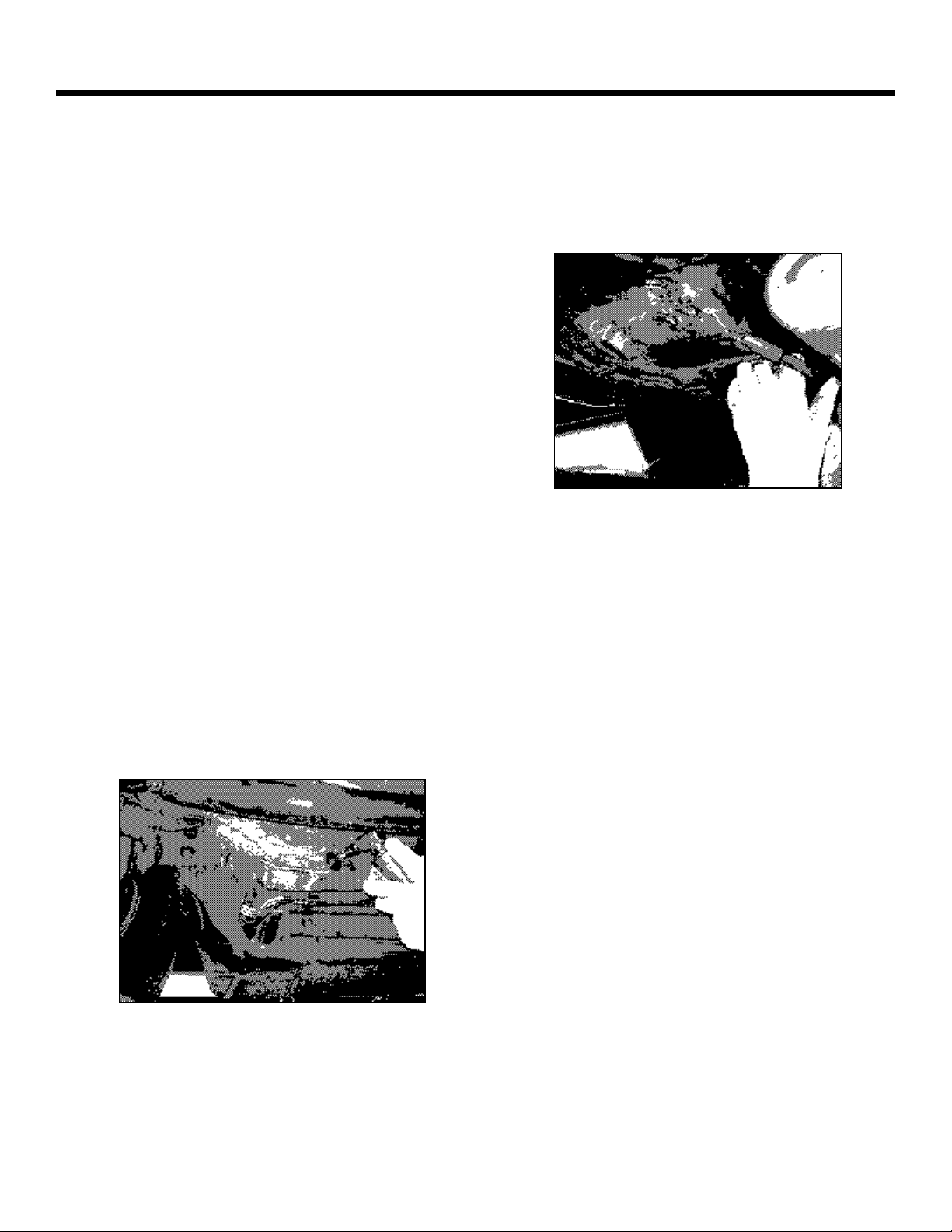
4. Using the subframe connectors as a guide, mark
where there needs to be welding on the floor
pan and using the angle grinder / sander, clean
the area to be welded. The cleaner the area
where the weld is to be, the better and stronger
the weld will be (see Figure 1).
5. Weld all the floor pan pieces that are spot weld
at the factory and will be covered by the
subframe connectors after installation. This will
help the subframe connectors and keep the
factory spot welds from breaking where they
would be inaccessible after installation (see
Figure 2).
Fig. 2
6. Using the supplied nut tab, bolt, and washer
install the Edelbrock Subframe Connectors on
the vehicle. Slip the nut tab through the hole by
the pinch weld near the rear trailing arm location;
align it so the hole in the subframe connector
can be bolted up. Before completely tightening
the bolt, it will be necessary to install the seat
reinforcement brackets. The seat reinforcement
bracket installs with the connector slipping
through the notch in the bracket and the longest
tab of the bracket to the front of the vehicle. Bolt
the seat reinforcement brackets using the
supplied 10mm bolts and washers, going up
from the bottom through the brackets into the
factory nut plates welded to the floor pan. (see
Figures 3 & 4). In the front subframe area, make
sure the connector is seated up against the floor
pan. The gaps between the sheet metal and the
subframe connector should be minimized for
good weld quality. Use C-clamps or locking
pliers to hold the front of the connector in place.
©2002 Edelbrock Corporation
Fig. 1
Page 2 of 3
Rev. 1/02
Page 3

9. Paint the Edelbrock Subframe Connectors at
this time to prevent corrosion. Re-install any
wiring, brake lines, and or fuel lines and mount
them securely. Now is a good time to inspect
the condition of the suspension components,
check for worn, loose, or broken components
and replace accordingly. The Edelbrock
Subframe Connectors will do the most for a
vehicle with good suspension parts.
Fig. 3
Fig. 4
7. Begin welding by tack welding both the front
then the rear of the subframe connector to the
floor pan. Once it is securely tack welded in,
then start to do the final welding. Weld the seat
bracket to the subframe connectors securely. It
may be necessary to lift the connector bar to
meet and close any large gaps between the
connector and the seat reinforcement bracket.
10. Re-install the interior pieces in the front foot
wells; install front seat mount hardware with the
supplied nyloc nuts and washers, onto the ends
of the bolts that are securing the seat
reinforcement brackets. Connect the battery.
Drive vehicle 20-30 miles and re-torque all the
mounting bolts.
Note: Please check our catalog to look into
other Edelbrock Suspension products to further
enhance the handling and performance of your
Mustang, such as coil springs, strut tower brace,
lower trailing arms, and shocks. To order a
catalog, call 1-800-FUN-TEAM.
8. Place the transmission cross member
reinforcement braces inside of the transmission
cross member mounting brackets, (see Figure
5) weld in place.
Fig. 5
©2002 Edelbrock Corporation
Page 3 of 3
Edelbrock Corporation
2700 California Street
Torrance, CA 90503
Tech Line: 1-800-416-8628
E-mail: edelbrock@edelbrock.com
Rev. 1/02
 Loading...