

Page 1
ADJUSTABLE TORQUE ARM
for 1984-2002 Camaro / Firebird
Catalog #5282
INSTALLATION INSTRUCTIONS
Please study these instructions carefully before installing your new adjustable torque arm. If you have any questions,
please contact our Technical Hotline at: 1-800-416-8628, 7:00 am to 5:00 pm, Monday through Friday, Pacific
Standard Time or e-mail us at edelbrock@edelbrock.com. Please fill out and mail your warranty card.
IMPORTANT NOTE: Proper installation is the responsibility of the installer.
Improper installation may result in poor performance and engine or vehicle damage.
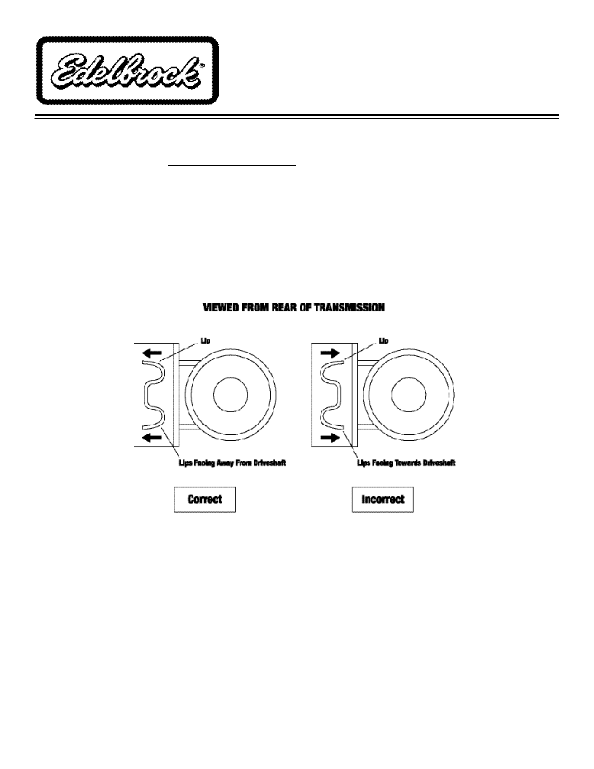
Application: This torque arm is designed to fit 1984-2002 Camaro and Firebird with 1) US built, GM corporate 10 bolt
rear ends that have 7 ½" or 7 5/8" ring gear and, 2) with front torque arm locator lips facing away from driveshaft
(See Fig. 1).
Fig. 1
PREPARATION CHECKLIST, TOOLS, AND EQUIPMENT REQUIRED:
❑ 4 Post drive on vehicle lift recommended, or ❑ Drill with &/32 drill bit or grinder (to remove
❑ Floor jack and 4 properly rated jackstands rivets)
❑ 13mm, 15mm, 21mm, &15/16” sockets and wrenches ❑ 1-1/8” crows foot wrench (to properly
❑ Torque wrench re-torque adjuster sleeve jam nuts)
❑ Magnetic angle finder gauge ❑ Thread locking compound
©2005 Edelbrock Corporation
Brochure No. 63-0482
Page 1 of 3
Catalog #5282
Rev. 12/05 - DA/mc
Page 2

BEFORE YOU GET STARTED
Before you begin the installation of your new adjustable
torque arm, it is very important that you inspect several
components on your vehicle for safety reasons, to
eliminate potential problems and to ensure your new
torque arm will work properly for a long time to come:
1. Inspect the motor mounts and the transmission
mount. Worn, weak or broken mounts will cause
the torque arm to not function properly and can
cause damage to your vehicle. Stock OE
transmission mounts in Camaros and Firebirds are
very weak and known to fail. If you have a broken
or weak transmission mount, it will cause the
torque arm to actually lift the tail end of the trans.
up. This could cause severe wheel hop, driveline
misalignment and possible damage to the
transmission, drive shaft, u-joints, rear axle,
torque arm, and/or floor pan of vehicle. We highly
recommend using a good quality polyurethane
transmission mount like Energy Suspension #33-
1108. Using the Energy Suspension transmission
mount is good insurance that your transmission
stay solid and the torque arm will work to its full
potential.
has a job and relies on the other components to do
their jobs. The installation of a high performance
torque arm alone will not mask worn or inferior
components. Use of an adjustable panhard rod
like Edelbrock (#5222) will allow you to re-center
your rear axle if your cars ride height has been
altered. We would like to stress the importance of
having a good solid chassis and suspension
system. Using Edelbrock products can help make
your car much safer as well as more fun to drive.
NOTE: Do not make any adjustments to your new
torque arm prior to installation. Your new torque arm
comes adjusted to stock configuration. Pinion angle
adjustments are very tricky and should only be done by
someone with a good understanding and the knowledge
of how to make proper adjustments. If adjustments are
made to pinion angle, it is very important that the rod
ends sit straight up and down and not angled between
the differential bracket, and that you have a minimum of
1" of thread engagement in the adjuster sleeve and rod
ends or it could cause the part to fail. Improper
adjustment, defective, worn, or inadequate suspension
components as mentioned above could cause torque
arm to fail causing damage or injury. Edelbrock Corp. is
not responsible for any damage or injury.
2. Inspect the rear suspension bushings. We strongly
recommend using either Edelbrock (#5274) lower
trailing arms with a spherical ball on one end and
polyurethane bushings on the other, Edelbrock
(#5204) trailing arms with polyurethane bushings
on both ends, or other high quality trailing arms
that use high quality polyurethane bushings. We
also recommend the use of an Edelbrock or other
high quality panhard rod to replace the stock OE
piece that uses sponge rubber bushings. The
lower trailing arms and panhard rod secure the
rear axle under the car. Upgrading to stronger
high quality tubular trailing arms and panhard rod
with polyurethane bushings will increase the
overall strength, eliminate the sponge feel of
rubber bushings and further increase the function
potential of the torque arm. Worn out trailing arm
or panhard rod bushings can contribute to or
cause torque arm or other suspension component
failures. Remember each suspension component
A drive on vehicle lift is recommended for proper and
easy installation.
Before you start, check and record current pinion angle.
(NOTE: Vehicle should be on level surface and in correct
ride position to obtain correct information.)
INSTALLATION INSTRUCTIONS
1. If you are not using a drive on lift, raise vehicle and
support under the frame so the rear end can be
raised and lowered, if needed.
2. Remove the two large bolts that attach the stock
arm to the differential and remove stock torque
arm. Inspect bolts and replace, if necessary. (Use
only OE bolts and OE style lock nuts)
3. Unbolt and remove the front bushing bracket
assembly from the transmission.
©2005 Edelbrock Corporation
Brochure No. 63-0482
Page 2 of 3
Catalog #5282
Rev. 12/05 - DA/mc
Page 3

4. Drill or grind off the rivet heads (See Fig. 2)and
disassemble bracket assembly and discard the
factory rubber bushing.
7. Apply supplied grease to the inside of the new
front bushing and slip onto the torque arm with
the part number on the bushing facing the rear of
the vehicle.
8. Position the polyurethane bushing in the inner
bracket and install the outer bracket, then (using
thread locking compound) install the upper bolt
and tighten both bolts and stud to factory
specifications.
9. At this time, torque the rear differential attaching
bolts to 97 ft. lbs.
10. After driving the vehicle 10-20 miles, it is very
important to re-torque all hardware OE
differential bolts (97 ft.lbs.). Pre-installed bolts
that attach the torque arm to the differential
bracket (150-160 ft. lbs.). Rod end jam nuts (90
ft. lbs. using 1-1/8" crows foot on torque
wrench).
Fig. 2
5. Re-install the inner bracket onto the transmission
with only the lower bolt and stud at this time. (Use
thread locking compound).
6. Install the new torque arm onto the rear end with
the factory OE bolts. (Use thread locking
compound on threads). Do not torque at this
time!). Due to production tolerances, it may be
necessary to file or grind the lower rear corner of
the differential casting to allow the differential
bracket to sit flush against the housing (Fig. 3).
NOTE: To maintain safe and trouble-free operation,
suspension and chassis components should be
periodically checked for condition, and hardware
should be checked with a torque wrench to factory
recommended specifications.
OTHER SUSPENSION UPGRADES FOR F-BODIES
AVAILABLE FROM EDELBROCK:
Strut tower brace, tubular lower trailing arms,
trailing arm relocation brackets, tubular
panhard rod, sub-frame connectors, coil
springs, adjustable front coil over assembles,
and shocks.
©2005 Edelbrock Corporation
Brochure No. 63-0482
Fig. 3
Page 3 of 3
Edelbrock Corporation
2700 California Street
Torrance, CA 90503
Toll-Free Tech Line: 1-800-416-8628
Tech E-Mail: edelbrock@edelbrock.com
Catalog #5282
Rev. 12/05 - DA/mc
 Loading...