

Page 1
©
2008 Edelbrock Corporation
Rev. 3/08 - AJ/mc
Catalog #5213, #5214
Brochure #63-5213
Page 1 of 2
Edelbrock Anti-Hop Bars
for 1964-1972 GM A-Body (Catalog #5213)
& 1978-1987 GM A/G Body (Catalog #5214)
INSTALLATION INSTRUCTIONS
Please study these instructions carefully before installing your new anti-hop bars. If you have any questions, contact our
Technical Hotline at: 1-800-416-8628, 7 am to 5 pm, Monday-Friday, Pacific Standard Time or e-mail us at
Edelbrock@Edelbrock.com.
Tools and Supplies Required:
❑ Jackstands ❑ Torque Wrench (70 lb. min.)
❑ Tire Chocks ❑ Drill Motor
❑ 1/4” Drill Bit ❑ Grease Gun
❑ Floor Jack ❑ Thread Lock Compound
❑ 7/16” & 3/4” Sockets and Wrenches
Caution: Installation requires being under raised vehicle. Support vehicle on level and stable ground using proper load
rated stands.
Note: Differential fill plug will not be accessible after installation. Check/change differential fluid before installation. The
right anti-hop will have to be removed to check fluid. After install, a fill plug style rear cover could be added.
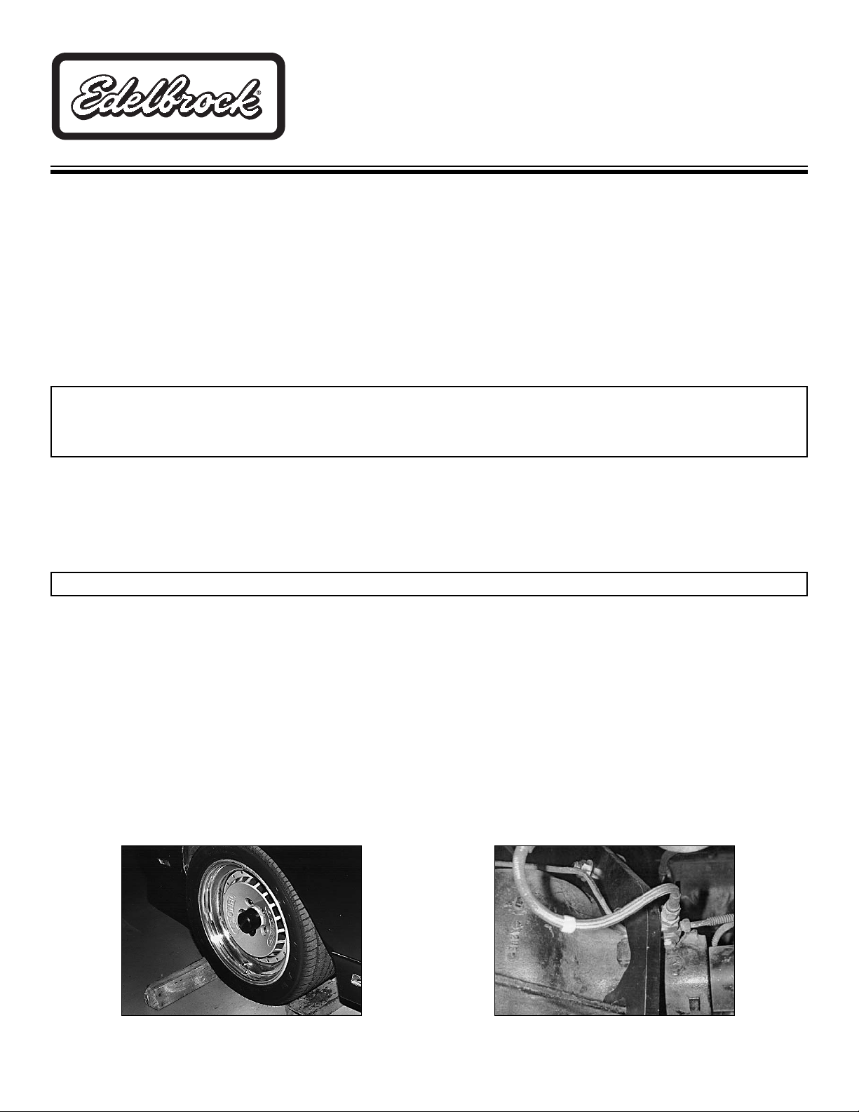
1. Place vehicle on level stable ground (i.e. concrete or driveway). Chock front wheels at front and rear of tire
(Fig.1).
2. Raise rear of vehicle and support so to keep rear suspension loaded with vehicle weight. Removing rear tires is not
required but can be helpful.
3. During installation it is critical to maintain pinion angle. To do this, use floor jack to support pinion area of rear end
housing. NOTE: An angle finder can be used to measure pinion angle.
4. Remove left upper trailing arm bolt from rear end bushing and loosen front trailing arm bolt. Rotate trailing arm up
and out of way. On 1978-1987 A/G cars, remove brake line distribution block bolt.
5. Remove pressed-in O.E.M. rubber bushing with caution so as to not damage rear end housing.
6. Install left anti-hop bar with grease fitting facing rear of vehicle. (Left bar in #5213 will be stamped with #25-4027
and #5214 will be stamped with #25-4038). Minor moving of brake line may be required on some years and models.
On #5214 use 5/16” bolt, nut and bracket to relocate line
(Fig. 2).
IMPORTANT NOTE:
Proper installation is the responsibility of the installer. Improper installation will void warranty and may
result in poor performance and engine or vehicle damage.
INSTALLATION INSTRUCTIONS
Fig. 1
Fig. 2
Page 2
©
2008 Edelbrock Corporation
Rev. 3/08 - AJ/mc
Catalog #5213, #5214
Brochure #63-5213
Page 2 of 2
Edelbrock Corporation, 2700 California St., Torrance, CA 90503
Tech Line: 1-800-416-8628
E-Mail: Edelbrock@Edelbrock.com
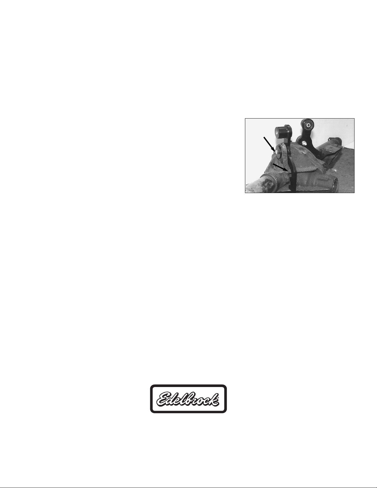
7. Locate anti-hop bar on steel bushing and 1/2"
(Fig. 3)
snug at this time.
8. Install upper trailing arm on anti-hop bar urethane bushing.
9. Drill 1/4" hole through axle housing web using anti-hop bar as guide. NOTE: Make sure to have at minimum 1/4" of
material between bolt hole and web edge,
(Fig. 2).
10. Install 1/4" bolt, washer and nyloc nut. Tighten bolt to 20 ft/lbs.
11. Use thread lock compound on upper trailing arm and steel bushing bolts and torque to 70 ft/lbs.
12. Remove right upper trailing arm bolt from rear end bushing and loosen front trailing arm bolt. Rotate trailing arm up
and out of way.
13. Remove pressed in O.E.M. rubber bushing with caution so as to not damage rear end housing.
14. Install right anti-hop bar with grease fitting facing rear of vehicle. (Right bar in #5213 is marked #25-4028, #5214 is
marked #25-4039).
15. Locate anti-hop bar on steel bushing and 1/2 bolt
(Fig. 3)
, snug at this
time.
16. Install upper trailing arm on anti-hop bar urethane bushing.
17. Drill 1/4" hole through axle housing web using anti-hop bar as guide.
NOTE: Make sure to have minimum of 1/4" of material between bolt hole
and web edge.
18. Install 1/4" bolt, washer and nyloc nut torque to 10 ft/lbs.
19. Use thread lock compound on upper trailing arm and steel bushing bolts
and torque to 70 ft/lbs.
20. Although Edelbrock anti-hop bar bushings are prelubed, you may want to lub the bushings. Install zerk fitting covers
to prevent dirt and corrosion of the zerk fittings.
Check hardware tightness after 10 miles and on a regular basis.
Note: To further upgrade your suspension, use other Edelbrock suspension, springs and shocks. See an Edelbrock
dealer or go to our website at www.edelbrock.com.
Fig. 3
Steel Bushing
and Bolt
Grind here,
if needed.
 Loading...