

Page 1
©
2006 Edelbrock Corporation
Rev. 9/06 - DA/mc
Catalog #5204 & #5205
Brochure #63-5204
Page 1 of 2
Edelbrock Lower Trailing Arms
Vehicle Applications: See Below
Catalog #5204 & #5205
INSTALLATION INSTRUCTIONS
Please study these instructions carefully before installing your new Trailing Arms. If you have any questions, contact our
Technical Hotline at: 1-800-416-8628, 7 am to 5 pm, Monday-Friday, Pacific Standard Time or e-mail us at
Edelbrock@Edelbrock.com.
Vehicle Applications:
Catalog #5204 - 1982-2002 Camaro/Firebird &
1978-1988 GM A/G-Body
Catalog #5205 - 1964-1972 GM A/G-Body
Tools and Supplies Required:
❑ Floorjack ❑ 18mm socket and combination wrench (3/4” for #5205 only)
❑ Jackstands ❑ Torque wrench
❑ Tire chocks ❑ Blue Loctite™
❑ Lug wrench ❑ Grease gun
NOTE: Edelbrock Trailing Arm hardware kits are available - Hardware Kit #5215 fits 5201 & 5204; #5217 fits #5205
(Optional - stock hardware may be re-used if in satisfactory condition).
REMOVAL OF STOCK TRAILING ARMS
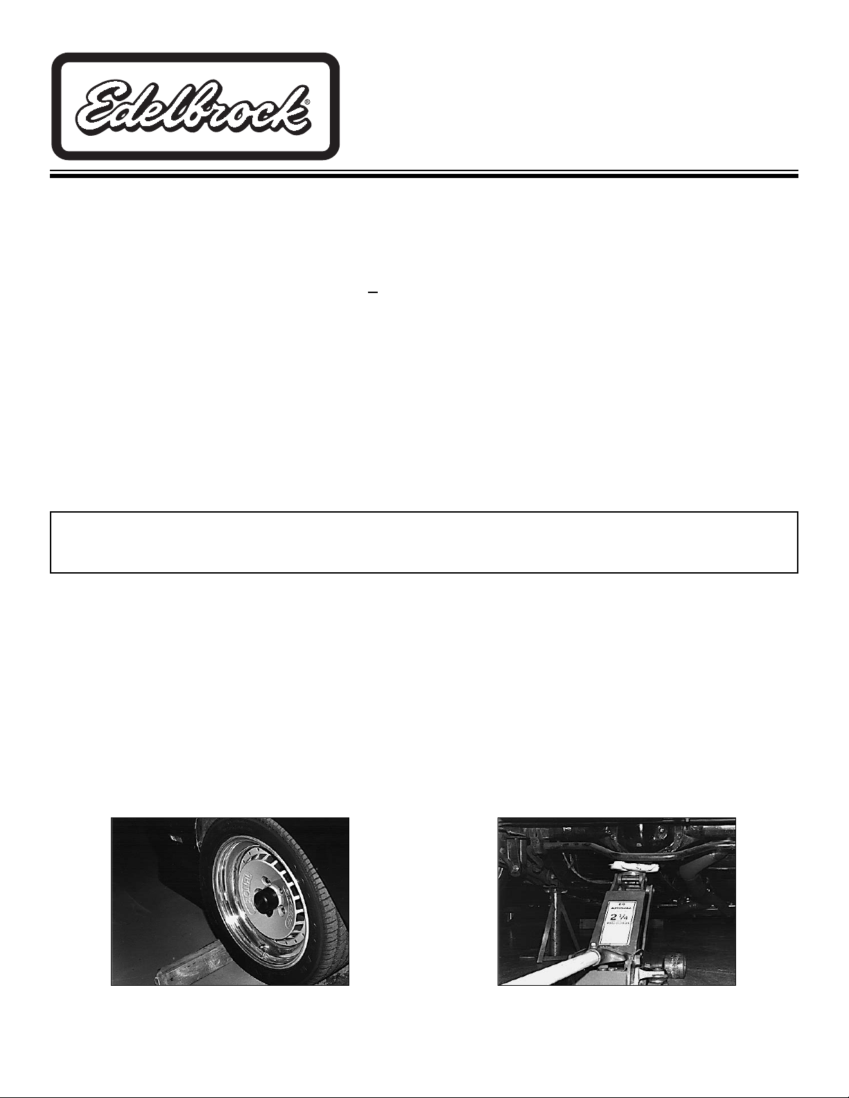
1. Place car on level surface and place tire chocks in front of and behind front tires
(Fig. 1).
2. Support rear of the car on jack stands and remove the rear wheels.
3. Place a floor jack under the differential and lift up slightly to remove tension from the trailing arm bolts - make sure
not to lift the car off the jackstands
(Fig. 2).
KEEP FLOOR JACK UNDER CAR DURING THE COMPLETE REMOVAL AND INSTALLATION PROCEDURE
CAUTION
- DO NOT REMOVE BOTH TRAILING ARMS AT THE SAME TIME OR THE AXLE WILL ROTATE AND THE
TRAILING ARM INSTALLATION WILL BE MUCH MORE DIFFICULT.
IMPORTANT NOTE:
Proper installation is the responsibility of the installer. Improper installation will void warranty and may
result in poor performance and engine or vehicle damage.
Fig. 1
Fig. 2
Page 2
©
2006 Edelbrock Corporation
Rev. 9/06 - DA/mc
Catalog #5204 & #5205
Brochure #63-5204
Page 2 of 2
Edelbrock Corporation, 2700 California St., Torrance, CA 90503
Tech Line: 1-800-416-8628
E-Mail: Edelbrock@Edelbrock.com
Fig. 4
Fig. 5
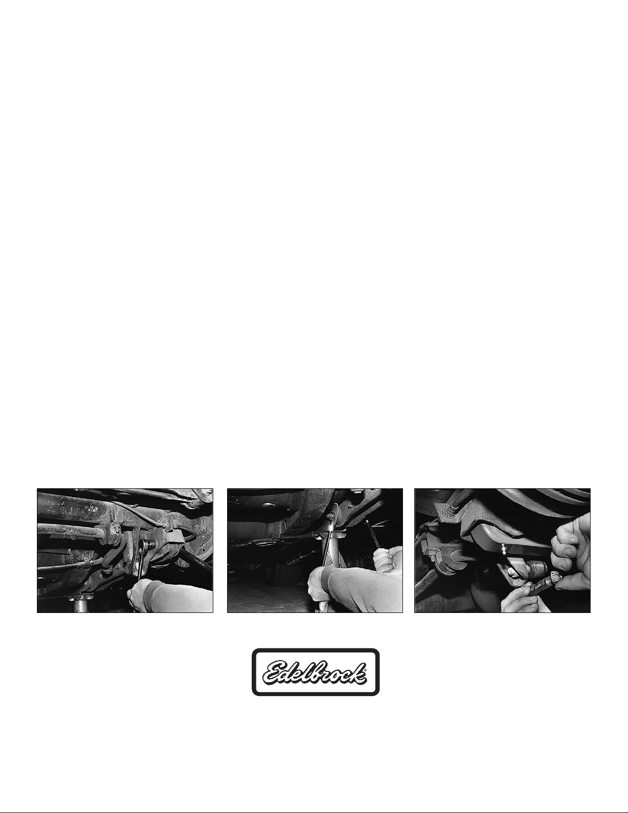
4. If sway bar mounts to trailing arms, remove at this time. Start with either trailing arm and remove the rear bolt
(Fig. 3).
Note: Replace the bolts in same orientation as original.
5. Remove the front trailing arm bolt using a socket with an extension - place the socket through the outer hole in the
frame to loosen the nut
(Fig. 4).
Caution: Be careful not to drop the bolt into the frame - if you do, then remove the bolt through the large hole on
underside of the frame using magnet, etc.
6. Remove the unbolted trailing arm.
7. If you are having difficulty removing the trailing arm bolts, then remove the lower shock bolts and the rear springs to
aid bolt removal.
8. Clean frame at trailing arm pivot area with a wire brush.
INSTALLATION OF EDELBROCK TRAILING ARMS
Edelbrock Trailing Arms are fully assembled, greased, and ready to install.
1. Install new trailing arms with the grease fittings facing down, with sway bar bolt holes towards the rear of car.
2. Install the new trailing arm by locating the front bolt first.
3. Place one drop of blue Locktite™ on clean threads and torque the nut to 70 ft./lbs
(Fig. 5).
4. The trailing arm should then pivot smoothly on the chassis.
5. Install the rear bolt.
6. Place one drop of blue Locktite™ on clean threads and torque the nut to 70 ft./lbs.
7. Re-install sway bar (if removed).
8. Although Edelbrock Trailing Arms are pre-lubed, you may want to finish your installation by
lubing the front and rear bushings with a grease gun. Be sure to replace the dust caps on the zerk fittings to prevent
dirt and corrosion from damaging the fitting.
Re-check all nut and bolt tightness after first 10 miles.
Note: To further upgrade your suspension, use other Edelbrock suspension products such as springs, shocks, torque
arm, panhard rod, subframe connectors, strut tower brace, etc. For more information, go to our website at
www.edelbrock.com.
Fig. 3
 Loading...