

Page 1

©2005 Edelbrock Corporation
Brochure #63-0425
Catalog #4771, #4774, #4778
Revised 11/05 - RS/mc
Page 1 of 3
PERFORMER X INTAKE MANIFOLDS
For Honda/Acura B-Series Engines
Catalog #4771, 4774, & 4778
INSTALLATION INSTRUCTIONS
PLEASE study these instructions carefully before beginning this installation. Most installations can be accomplished with common tools and
procedures. However, you should be familiar with and comfortable working on your vehicle. If you do not feel comfortable performing this
installation, it is recommended to have the installation completed by a qualified mechanic. If you have any questions, please call our Technical
Hotline at: 1-800-416-8628, 7:00 am - 5:00 pm, Pacific Standard Time, Monday through Friday or e-mail us at edelbrock@edelbrock.com
.
IMPORTANT NOTE: Proper installation is the responsibility of the installer.
Improper installation may result in poor performance and engine or vehicle damage.
WARNING: When working around gasoline or with any fuel system, always work in a well-ventilated area. Keep all sparks, open
flames, or other sources of ignition away from the work area. Failure to do so could result in a fire or explosion causing vehicle
or property damage, personal injury, and/or death.
PLEASE complete and mail your warranty card. Be sure to write the model number of this product in the "Part #____" space. THANK YOU.
DESCRIPTION: Designed for Honda/Acura B-Series engines, Performer X Intake Manifolds are optimized for the 3500-8500 RPM range. They
feature 9” long, tapered runners for optimal air flow and a rectangular plenum to accentuate the natural tuning waves of the runners. These
features are ideal for performance street vehicles using a naturally-aspirated or forced induction setup. A 66mm throttle body opening allows the
use of oversized throttle bodies with no machining necessary. The angled throttle body pad improves air-flow and provides a better fit in stock
engine compartments. Manifolds include four (4) partially machined secondary injector bosses, which may be drilled through for applications
requiring a secondary fuel system, such as turbocharged, or alcohol-fueled engines (Use Secondary Fuel Rail Kit #4779). Performer X manifolds
accept all factory emissions components and are a direct replacement for the stock intake manifold, making them 50 state emissions legal.
APPLICATIONS:
INTAKE MANIFOLD APPLICATION
4771 Honda/Acura vehicles using the B18C1 engine. Typically found in 1994-2001 Acura Integra
4774 Honda/Acura vehicles using the B16A (USDM or JDM) or the B18C5 (Type-R) engine. The
B16A is usually found in the Honda Del Sol VTEC or 1999-2000 Honda Civic Si. The B18C5
is original equipment for the Acura Integra Type-R.
4778 Honda/Acura vehicles using a B18 series, non-VTEC engine. These are usually referred to as
the “LS” engine. These engines are commonly found in 1990-2000 Acura Integra GS, RS, or
LS models.
KIT CONTENTS:
❑ 1 Throttle Cable Bracket
❑ 3 Fuel Rail Spacers
❑ 1 MAT Sensor Block-Off Plate
❑ 1 MAT Sensor Block-Off Plate Gasket
❑ 1 Throttle Body to Intake Manifold Gasket
❑ 2 M5 x 12mm Torx Head Screws With Integral Washers
❑ 2 8mm x 1.25 x 40mm Allen Head Bolt
(4774 ONLY)
❑ 2 8mm Washers
(4774 ONLY)
❑ 1 1/8” NPT x 3/8” Hose Barb Fitting
❑ 2 1/8” NPT x 3/16” Hose Barb Fitting
❑ 2 1/8” NPT x 8mm Hose Barb Fitting
❑ 1 1/4” NPT x 8mm Hose Barb Fitting
❑ 1 1/4” NPT x 9mm Hose Barb Fitting
❑ 1 1/4” NPT x 10mm Hose Barb Fitting
❑ 1 3/8” NPT x 17mm Hose Barb Fitting With 1/8” NPT Female
Side Port
❑ 4 1/8” NPT Pipe Plug
❑ 2 1/4” NPT Pipe Plug
❑ 1 3/8” NPT Pipe Plug
❑ 1 12” of 18 Gauge Yellow Wire
(4771 ONLY)
❑ 1 12” of 18 Gauge Blue Wire
(4771 ONLY)
❑ 4 18 Gauge Splice Connectors
(4771 ONLY)
®
Page 2
1. Disconnect the battery and disconnect the air intake tube from
the throttle body. Drain the engine coolant by loosening the
petcock at the bottom of the radiator. Use a drain pan to collect
drained coolant. Keep the coolant clean and free of dirt and
debris, it can be re-used later
NOTE: On some vehicles, it may be necessary to remove the oil
filter (Remember to re-install BEFORE starting engine) to access
the intake manifold support bracket, and to remove the bracket
from the underside of the vehicle. This simplifies the removal of
the stock intake manifold. The support bracket is not necessary
with the Performer X intake manifold.
2. Relieve fuel pressure by loosening the banjo bolt connecting the
fuel line to the fuel filter. Place a shop towel or rag over the
wrench while loosening the banjo to soak up any fuel spray
(See
Fig. 1)
. When loosening or tightening the banjo bolt on the fuel
filter can, use a 19mm
wrench on the hex of the
fuel filter can to
counteract the torque of
loosening or tightening
the banjo bolt. This will
prevent the fuel filter can
and bracket from being
improperly loaded during
loosening or tightening at
the banjo bolt.
3. Disconnect the fuel injector wiring harness from the bracket on
the fuel rail and unplug the harness from the fuel injectors.
Disconnect the Throttle Position Sensor, Manifold Air Pressure
(MAP) Sensor, and Idle Air Control Motor connectors.
NOTE: Always mark connectors before removal. Some sensors
have same plug ends. Also mark the locations of each fuel
injector plug on the harness to prevent improper connection
during re-installation.
4. Disconnect the purge line from the EVAP Purge Valve. Disconnect
the fuel return line from the steel chassis fuel line. Disconnect the
fuel line from the fuel filter.
NOTE: FUEL WILL DRAIN from the detached fuel lines. Use care
to prevent fuel from spilling excessively.
5. Disconnect the coolant lines from the throttle body and manifold
flange.
NOTE: Some coolant will drain from the coolant lines leading into
the intake manifold when they are disconnected.
6. If the intake manifold support bracket was not removed
previously, remove the bolts at the rear of the stock manifold
attaching the manifold to the support bracket. Disconnect the
vacuum lines at the rear of the manifold. Remove the throttle
cable. Remove the factory intake manifold nuts. Remove the
stock intake manifold assembly and set aside. If the manifold
support bracket was not previously removed, finish removing the
bracket.
7. Stuff the open intake ports in the cylinder head with paper towels
to prevent any debris from entering the engine. Thoroughly clean
the gasket surface removing any remaining sealant or gasket
material. The gasket surface must be clean and free of any old
gasket material in order to prevent sealing problems.
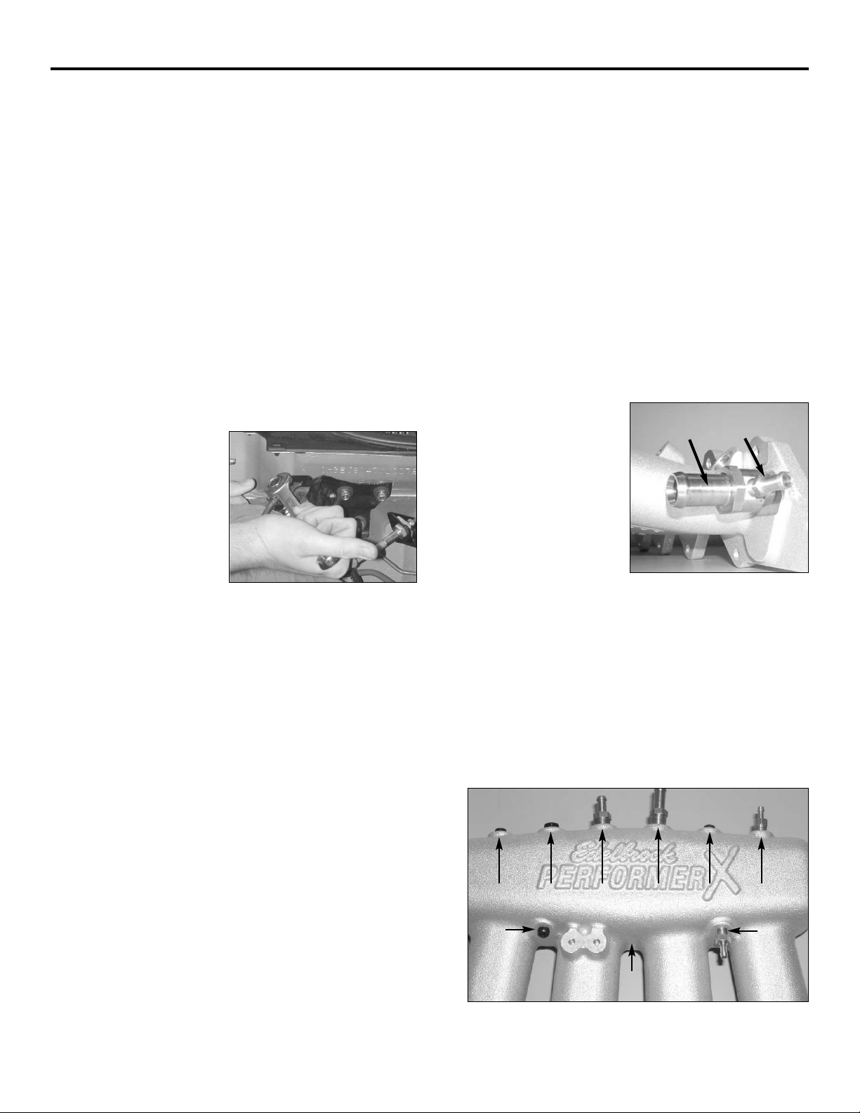
8. Install the water outlet
fitting into the mounting
flange. Install the 1/8”
NPT x 8mm barb into the
water outlet fitting if your
application supplies
coolant to the throttle body
from the intake flange
(See Fig. 2A)
.In
applications where the
throttle body coolant line is
routed from the cylinder head, install a 1/8” NPT pipe plug in the
water outlet fitting instead. Install the vacuum fittings and the
stock Manifold Air Temperature (MAT) Sensor on the back side of
the Performer X intake manifold
(See Fig. 2B)
. Some
applications may use a MAT sensor that is not mounted on the
intake manifold. In those applications, install the supplied block
off plate using the supplied gasket and M5 x 12mm Torx screws.
NOTE: See Fig. 2C on page 3 for fitting descriptions.Use teflon
paste on the threads of fittings before installing them into the
intake manifold. Use additional supplied fittings and plugs as
necessary for your application.
©2005 Edelbrock Corporation
Brochure #63-0425
Catalog #4771, #4774, #4778
Revised 11/05 - RS/mc
Page 2 of 3
INSTALLATION PROCEDURE
Fig. 2B
Fig. 2A
#3 #4 #5 #6 #7 #8
#2
#1
Fig. 1
BEFORE BEGINNING: If you wish to use the Performer X intake manifold with a secondary fuel system, use Edelbrock Secondary Fuel Rail Kit
#4779, and perform the preparation for the secondary fuel rail before beginning the intake manifold installation. The intake manifold must be
removed from the engine in order to install the secondary fuel rail kit.
#9 #11
#10
Page 3

11. Connect all factory sensors, coolant lines, and vacuum hoses.
Connect the factory fuel injector wiring harness to the stock fuel
injectors, and reattach the harness to the fuel rail bracket.
Special Instructions for #4771: In some cases, the idle air
control motor (IAC) wire harness will no longer reach the solenoid.
Use the supplied wires and connectors supplied in kit to extend
the factory wire harness.
12. Connect the stock throttle cable to the Edelbrock bracket and
following the factory service manual, adjust the throttle cable for
proper operation.
13. Connect the fuel supply line to the fuel filter and connect the fuel
return line. Refill the coolant to the factory specified level.
14. Turn the key to the engine “on” position and check for fuel leaks.
Fix any leaks before starting the engine. Start the engine and
check for water and/or fuel leaks. If leaks are present, shut off
engine immediately, and repair any leaks before continuing.
9. Remove Idle Air Control
motor (IAC) from
factory intake manifold
and install onto the
Performer X intake
manifold. Remove the
throttle body (with MAP
sensor attached), and
two throttle body studs
from the factory intake
manifold. Using two throttle body nuts on each stud, and
jamming them, will help get the studs out of the stock intake
manifold
(See Fig. 3)
. Install the two throttle body studs into the
Performer X intake manifold, one on the upper right bolt hole of
the throttle body mounting flange and one on the lower left bolt
hole. Install the throttle body onto the Performer X manifold using
the supplied gasket. Install the supplied throttle cable bracket
onto the Performer X manifold using the stock bolts. Remove the
stock fuel rail / injectors / fuel pressure regulator assembly and
the stock fuel-rail-studs and spacers and install onto the
Performer X manifold using the stock hardware.
NOTE: Inspect all o-rings and seals for wear, and replace if
necessary. Also, make sure each injector can rotate freely in its
bore after being installed, and the fuel rail hold down bolts/nuts
have been fully tightened.
Certain models and years did not use fuel rail spacers (such as
Integra Type-R and late Integra LS models). These applicatons
may require the use of fuel rail spacers in order to install the
Performer X intake manifold. If necessary, use the supplied fuel
rail spacers in those applications.
NOTE: If installing intake manifold 4774 in an application
requiring Edelbrock fuel rail spacers, use spacers with the
supplied 8mm x 1.25 x 40mm allen bolts and 8mm washers.
©2005 Edelbrock Corporation
Brochure #63-0425
Catalog #4771, #4774, #4778
Revised 11/05 - RS/mc
Page 3 of 3
Edelbrock Corporation • 2700 California St. • Torrance, CA 90503
Tech-Line: (800) 416-8628 • E-Mail: Edelbrock@Edelbrock.com
Fig. 3
Fig. 4 - Intake Manifold Tightening Sequence
(Torque nuts to 17 ft./lbs. in two or three steps,
following sequence above.)
#1 3/8” NPT x 17mm Barb (Manifold Water Outlet)
#2 1/8” NPT x 8mm Barb (Throttle Body Coolant Hose) or 1/8”
NPT Pipe Plug (If coolant hose is routed from cylinder head)
#3 1/8” NPT Pipe Plug
#4 1/4” NPT Pipe Plug (FPR
#5 1/4” NPT x 9mm Barb (Purge Valve Hose)
#6 1/4” NPT x 10mm Barb (Power Brake Booster Hose)
#7 1/8” NPT PIpe Plug
#8 1/8” NPT x 3/16” Barb (Vacuum Operated Cruise Control) or
1/8” NPT Pipe Plug (Non-Vacuum Cruise)
#9 1/8” NPT Pipe Plug
#10 Factory MAT Sensor, or Supplied Block-Off Plate
(Underside of Plenum, Not Pictured)
#11 1/8” NPT x 3/16” Barb (Fuel Pressure Regulator Hose)
Fig. 2C
10. Using a factory Honda intake manifold gasket, or equivalent
aftermarket gasket, install the Performer X manifold/throttle
body/fuel rail assembly onto the engine using the factory nuts
(See Fig. 4 for proper torque values and sequence)
.
NOTE: Remember to remove the paper towels or rags before
installing the intake manifold.
1
7
21036
549
8
 Loading...