

Page 1
Street/Strip Camshafts for
Honda/Acura B-Series VTEC Engines
,
Proper installation is the responsibility of the customer. Improper or incomplete installation could result in poor
performance, related component damage, potentially severe engine damage, and will void your warranty. If you do not feel
Catalog # 4730
INSTALLATION INSTRUCTIONS
PLEASE study these instructions carefully before installing your new Street/Strip Camshafts for Honda/Acura B-Series VTEC
Engines. If you have any questions or problems, do not hesitate to contact our Technical Hotline at: 1-800-416-8628
from 7am-5pm PST, Mon-Fri, or via e-mail at: Edelbrock@Edelbrock.com. Please fill out and mail your warranty card.
• Note:
comfortable installing these parts, we recommend having the installation performed by a professional mechanic.
• Description: The Street/Strip camshafts for Honda/Acura B-Series VTEC engines provide best performance up to 9000
RPM. They are ground from chilled iron and nitride hardened for outstanding durability. Due to the increased lift of these
camshafts, changing valve springs is required.
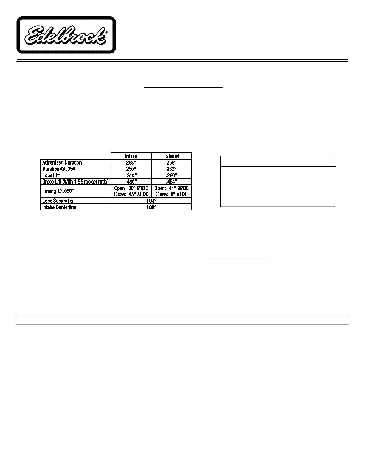
Cam Specifications (Vtec Lobe):
Kit Contents
Qty. Description
❑ 1 Intake Camshaft
❑ 1 Exhaust Camshaft
❑ 1 Container of Assembly Lube
• Recommended Related Products:
Due to the high rpm nature of the Street/Strip Camshafts, a programmable or modified ECU is recommended to overcome
the rev limiter for off-highway race vehicles only. Fine tuning on a dyno is recommended for maximum performance. We
recommend the use of Edelbrock Adjustable Cam Gears, #4721 (silver) or #4723 (red), to adjust cam timing for best
performance. To order a catalog, call (800) FUN-TEAM, or visit www.Edelbrock.com.
• Tools and Additional Parts Required:
1. Edelbrock #4737 - Street/Strip Valve Spring Kit
2. Honda #07AA-PR3020A - Tappet Adjuster Wrench
3. Socket Wrench with 10, 12, 14 & 19mm Sockets
(Long sockets or extentions may be required.)
4. 5/8” Spark Plug Socket Wrench
5. Long Feeler Gauges (.006” & .008”)
6. Adjustable Torque Wrench
7. Automotive Sensor Safe Silicone Sealant
INSTALLATION NOTES
• Note: Make sure your engine is in good running condition before installing the Edelbrock Street/Strip Camshafts. If your
engine is not in good working order, installation of these high performance camshafts could result in premature engine
wear. It is recommended to check the wear of the camshaft journals before installation by checking the oil clearance as
shown in the factory service manual. Checking the camshaft end-play, and rocker arm wear is also recommended.
• Remember: When working on your engine, especially when oil or fuel is present, always work in a well-
ventilated area. Keep all sparks, open flames, or other sources of ignition away from the work area. Failure
to do so could result in a fire or explosion causing vehicle or property damage, personal injury, and/or death.
• Before Beginning: This installation can be accomplished using common tools and procedures. However, you should have
a basic knowledge of automotive repair and modification and be familiar with and comfortable working on your vehicle. If
you do not feel comfortable working on your vehicle, it is recommended to have the installation completed by a professional
mechanic. Keeping your specific vehicle’s Service Manual on hand for reference is helpful.
©2003 Edelbrock Corporation
Rev. 10/03
Page 1 of 4
Catalog #4730
Brochure #63-0210
Page 2
INSTALLATION PROCEDURE
1. Make sure the engine is cool and the vehicle is on level
ground. Set the parking brake. If you have an original
equipment radio with anti-theft protection, make sure to
write down the code before disconnecting the battery.
After installation, you will need this code to restore radio
operation. It is recommended to clean the valve cover, as
well as the area surrounding the valve cover, to avoid
getting dirt or debris into the engine. Disconnect the
negative cable from the battery.
2. Disconnect the PCV hose and ground wire from the valve
cover. Using a 10mm socket, remove the four cap nuts
holding the spark plug wire cover. Remove the spark
plug wire cover and remove the spark plug wire boots
from the spark plugs. Using a 5/8” spark plug socket,
remove the spark plugs. This will make turning the
engine over in step 5 easier. Using a 10mm socket,
remove the remaining eight nuts and washers holding
the valve cover, and carefully lift off the valve cover.
(Note: Inspect the valve cover gasket and rubber
seals surrounding the spark plug holes. If they are
in good condition, they may be re-used). Set the
cover, gasket, and seals aside.
Check that the no. 1 cylinder is still at TDC. If not,
continue to rotate the crankshaft pulley counterclockwise until the no. 1 cylinder is again at TDC.
7. Remove the timing belt tensioner access plug and loosen
the belt tensioner adjusting bolt 1/2 turn using a 14mm
socket. Push on the belt tensioner to remove tension
from the timing belt, then tighten the adjusting bolt to
hold the tensioner in place.
8. You may now slide the timing belt off of the camshaft
sprockets.
9. Remove the cam sprocket bolts and remove the cam
sprockets, being very careful not to lose the cam keys
that locate the sprockets onto the camshafts. You may
now remove the bolt holding the back timing cover using
a 10mm socket. Remove the cover and inspect the seal
between the cover and the cylinder head; if it is in good
condition, it may be re-used.
10. Using the Tappet Adjuster Wrench, loosen the tappet
adjusting screws on all rockers.
3. Loosen and remove the three distributor mounting bolts
using a 12mm socket. Remove the distributor from the
cylinder head and rest it carefully next to the head, you
do not need to unplug the distributor from the wiring
harness. Be careful not to lose the o-ring seal. Inspect
the seal for damage. If it is in good condition, it may be
re-used.
4. Remove the two bolts holding the middle timing belt
cover using a 10mm socket. Remove the middle timing
cover and set aside.
5. Turn the steering wheel so the front tires are pointing to
the left. Now you can access the crankshaft pulley bolt
through the fender liner. Rotate the engine counterclockwise using a 19mm socket until the no. 1 cylinder is
at top dead center (TDC) on the compression cycle. The
no. 1 cylinder is at TDC when the white TDC mark on the
crankshaft pulley is aligned with the pointer on the lower
timing belt cover.
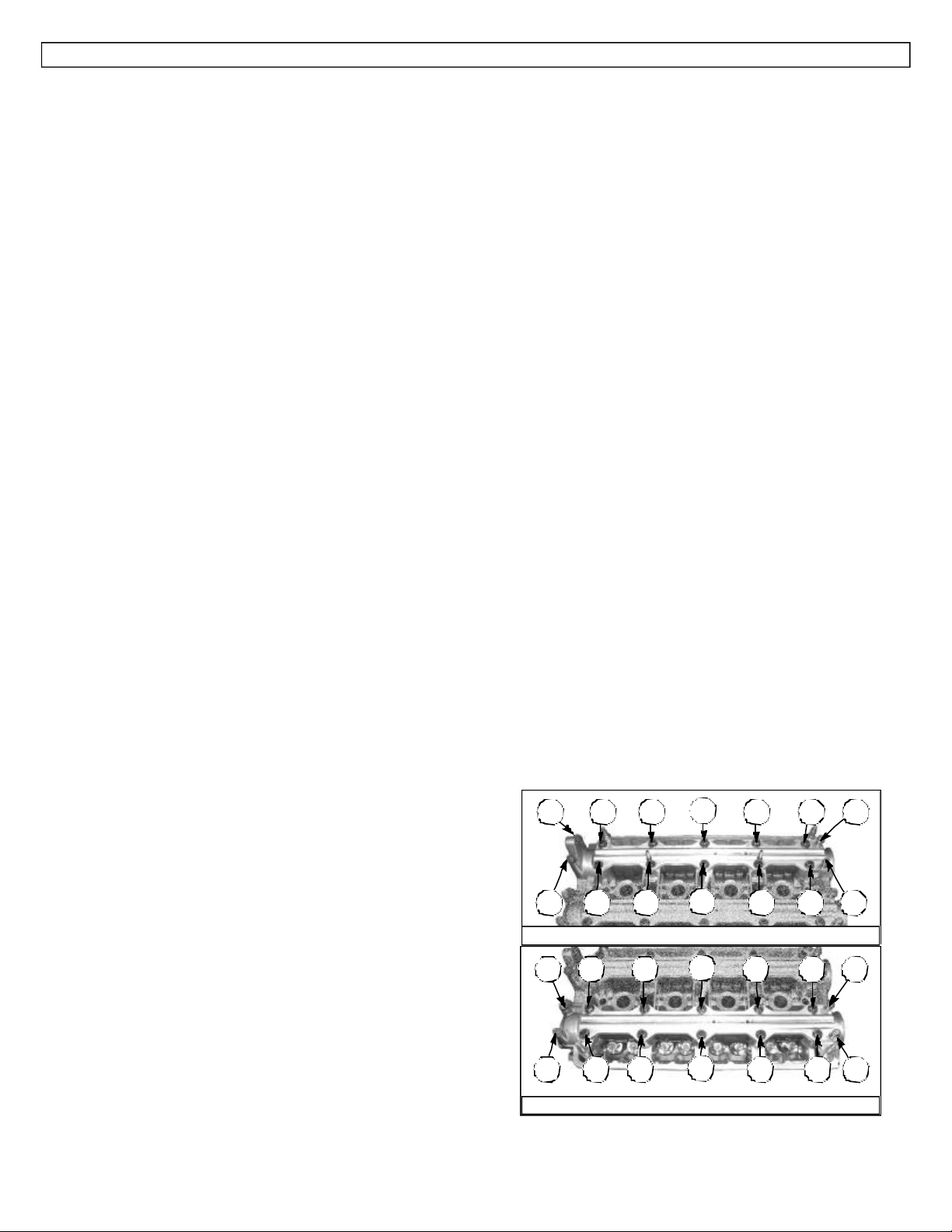
11. Loosen the bolts holding the camshaft holder plates and
camshaft holders (cam caps) using a 12mm socket on
bolts 1-10 and a 10mm socket on bolts 11-14 of each
set of camshaft holder plates (See Fig. 1-A & 1-B). To
prevent any possible warpage of the plates and cam
caps, loosen each bolt 1/3 turn at a time in the sequence
shown. Repeat until all bolts are fully loosened.
1
14 10 6
Fig. 1-A - Intake Cam Plate Torque Sequence
14 10 6
2
1
2
3 7
4 8 12
3 7
4 8 12
11913 5
11913 5
6. Using a 14mm socket, loosen the camshaft sprocket
bolts approximately 1/2 turn. Do not remove the bolts.
©2003 Edelbrock Corporation
Rev. 10/03
Fig. 1-B - Exhaust Cam Plate Torque Sequence
Catalog #4730
Brochure #63-0210Page 2 of 4
Page 3

12. Remove each plate carefully, keeping the intake cam
plate and exhaust plate in order, allowing the bolts to
remain in their positions in the plates. This will allow the
bolts to go back into their original positions and is an
easy way to keep them in order. Set the plates aside.
Carefully lift the cam caps off of the camshafts keeping
them in order. You will notice that each cap is marked
with an arrow and number that corresponds to its
location. The arrows point toward the timing belt, and
they are numbered with no. 1 being closest to the timing
belt and no. 5 being closest to the distributor. Make sure
to keep the bolts that hold the end cam caps in order as
well. (Note: You may need to pry the cam caps
loose before lifting them off. Carefully use a flat
blade screwdriver to pry the cam caps loose. See
Fig. 2). There is an oil seal and dowel pin under the no.
3 cam cap. Inspect the oil seal and replace, if necessary.
Carefully use a flat blade
screwdriver to lift cam caps.
DO NOT pry near the cam
journal surface. Wrap the end
of the screwdriver with tape
to protect the cam caps.
liberal coating of lube to the rocker arm contact surface
and to the journal suface in the cylinder head and on the
cam caps.
16. Set the camshafts into the head with the keyways facing
up. Apply some automotive sensor safe silicone to the
mating surfaces of the no. 1 and no. 5 cam caps (See
Fig. 3). Make sure the cam caps are in order and set
them down on top of the camshafts. Now install the cam
holder plates, and torque bolts #1 - 10 to 20 ft/lbs, and
bolts #11 - 14 to 7 ft/lbs (See Fig. 1).
No. 5 Cam Caps
Apply
automotive
sensor safe
silicone to
the lightened
areas shown.
No. 1 Cam Caps
Fig. 3
17. Install the back timing cover and gasket. Torque bolt to
7 ft/lbs. Install the cam sprockets, making sure to use
the cam keys. Hand tighten the cam sprocket bolts at
this time.
Fig. 2
13. Remove the camshafts one at a time, keeping them in
order. (Note: The oil seals will come out with the
camshafts. Take care not to damage the oil seals).
Now is a good time to inspect the rubber cap near the
end of the exhaust cam, opposite the timing belt. If it is
in good condition, it may be re-used. Make sure the oring sealing surface is clean and dry.
14. Remove the oil seals from the camshafts. If they are in
good condition, they may be re-used. Install the oil seals
onto the new Edelbrock Street/Strip Camshafts with the
spring side facing in towards the camshafts.
15. Apply a liberal coating of assembly lube to the journals
and lobes of the Edelbrock camshafts. Also, apply a
18. Slip the timing belt over the cam sprockets. Loosen the
belt tensioner adjusting bolt to allow it to tighten the belt.
Tighten the tensioner adjusting bolt to 40 ft/lbs. Tighten
the cam sprocket bolts to 40 ft/lbs. Make sure the cam
sprockets are aligned properly (See Fig. 4). If you can
rotate the belt more than 90° by hand, the belt is too
loose. Make sure the tensioner is not stuck by loosening
the tensioner adjusting bolt and pulling up on the
tensioner with a hook or bent wire hanger, then retighten the bolt. Replace the tensioner adjusting bolt
access plug.
Make sure sprockets are aligned
as shown. Stock sprocket “Up”
marks should point up with TDC
mark aligned as shown.
Fig. 4
©2003 Edelbrock Corporation
Rev. 10/03
Catalog #4730
Brochure #63-0210Page 3 of 4
Page 4

19. Rotate the engine 5-6 revolutions to seat the belt. Bring
the engine around to TDC as in step 5. Make sure the
cam sprockets are still aligned properly (See Fig. 4).
20. Replace the middle timing cover. Torque bolts to 7 ft/lbs.
24. Install the spark plugs and wires. Install the wire cover.
Tighten cap nuts to 7 ft/lbs. Connect the PCV hose and
the ground wire. Connect the negative battery cable.
21. Coat the distributor o-ring with clean engine oil, and
install the distributor. Tighten mounting bolts to 17 ft/lbs.
(Note: The distribitor shaft and end of camshaft
are notched to elimiinate the possibility of
installing the distributor 180° out of time).
22. Before installing the valve cover, you will need to adjust
the valves. Set the no. 1 cylinder at TDC as explained in
step 5. Make sure the cam sprockets are aligned
properly (See Fig. 4). Using the tappet adjuster wrench,
adjust the valve lash on the no. 1 cylinder. The intake
valve clearances should be set at .006” and the exhaust
valve clearances at .008”. The feeler gauge should slide
between the rocker arm and the camshaft with a slight
amount of drag. Tighten the lock nut and re-check the
clearance. It should stay at .006” (intake) and .008”
(exhaust). Turn the crankshaft 180° counter-clockwise.
The cams should have rotated by 90°. Repeat the valve
adjustment on the no. 3 cylinder. Rotate the engine 180°
again, and repeat the adjustment on the no. 4 cylinder.
Rotate again by 180° and repeat the adjustment on the
no. 2 cylinder. The valves are now adjusted. After
adjusting the valves, re-torque the crankshaft bolt to 130
ft/lbs.
Apply Here Apply Here
Apply automotive sensor safe
silicone to the corners of the seal
on both ends of the valve cover.
7
3
8
4 2
Fig. 5
5
1
6
23. Thoroughly clean the valve cover mating surface, being
careful not to get any old silicone or dirt into the engine.
Clean off the rubber cap near the exhaust cam, put a thin
coat of automotive sensor safe silicone around it and
install it. Clean the groove in the valve cover and press
the valve cover gasket into the groove in the valve cover.
Apply a bit of automotive sensor safe silicone at the
corners of the gasket that go around the camshafts (See
Fig. 5). Set the valve cover onto the cylinder head and
press down lightly to make sure the gasket is seated.
Install the four nuts and washers that go under the plug
wire cover and the four cap nuts and washers. Tighten
nuts to 7 ft/lbs (See Fig. 6 for torque sequence).
Edelbrock Corporation • 2700 California St. • Torrance, CA 90503
Tech Line: 1-800-416-8628 • Office: (310) 781-2222 • E-Mail: Edelbrock@Edelbrock.com
©2003 Edelbrock Corporation
Rev. 10/03
Fig. 6
• Camshaft Run-In Procedure:
Edelbrock recommends performing a Run-In procedure
after installing new camshafts. Make sure the oil level in
the engine is at the proper level, and the oil is clean. We
recommend using a non-synthetic oil during the break in.
Start the vehicle and immediately bring the engine above
2500 rpm for at least 20 minutes. Vary the engine speed
constantly to help sling oil around the camshafts. After
the run-in, change the oil to remove any assembly lube.
Catalog #4730
Brochure #63-0210Page 4 of 4
Page 5

CAMSHAFT: Street/Strip
Rev. 10/03
Rev. 10/03
CATALOG #: 4730
ENGINE: Honda, B-Series VTEC
RPM RANGE: Idle - 9000 RPM
CAMSHAFT: Street/Strip
CATALOG #: 4730
ENGINE: Honda, B-Series VTEC
RPM RANGE: Idle - 9000 RPM
Advertised Duration: Int. 288° Exh. 266°
Duration at .050” Lift: Int. 250° Exh. 232°
Lift at Cam: Int. .316” Exh. .293”
Lift at Valve: Int. .490” Exh. .454”
Intake Centerline: 100°
Lobe Separation: 104°
Timing at .050” Lift:
Open Close
Intake: 25° BTDC 45° ABDC
Exhaust: 44° BBDC 8° BTDC
Advertised Duration: Int. 288° Exh. 266°
Duration at .050” Lift: Int. 250° Exh. 232°
Lift at Cam: Int. .316” Exh. .293”
Lift at Valve: Int. .490” Exh. .454”
Intake Centerline: 100°
Lobe Separation: 104°
Timing at .050” Lift:
Open Close
Intake: 25° BTDC 45° ABDC
Exhaust: 44° BBDC 8° BTDC
Rev. 10/03
CAMSHAFT: Street/Strip
CATALOG #: 4730
ENGINE: Honda, B-Series VTEC
RPM RANGE: Idle - 9000 RPM
Advertised Duration: Int. 288° Exh. 266°
Duration at .050” Lift: Int. 250° Exh. 232°
Lift at Cam: Int. .316” Exh. .293”
Lift at Valve: Int. .490” Exh. .454”
Intake Centerline: 100°
Lobe Separation: 104°
Timing at .050” Lift:
Open Close
Intake: 25° BTDC 45° ABDC
Exhaust: 44° BBDC 8° BTDC
Rev. 10/03
 Loading...