

Edelbrock 4100, 4200, 4400, 41000 User Manual

©2007 Edelbrock Corporation
Catalog #65903
Page 1 of 2
Rev. 8/07-DA/mc
Brochure #63-65903
Edelbrock Race Header
For 1993-1997 F-Body, 5.7L, LT1
Catalog #65903
INSTALLATION INSTRUCTIONS
Please study these instructions carefully before installing your new Race Header. They provide general guidelines to be
studied and understood before you remove your stock system. Failure to follow these instructions may void your warranty.
If you have any questions, please contact our Technical Hotline at : 1-800-416-8628 from 7 am – 5 pm, Monday
through Friday, Pacific Standard Time or e-mail us at Edelbrock@Edelbrock.com
.
DESCRIPTION: Edelbrock race header components are designed to improve the exhaust efficiency of the F-body, 5.7L
LT1 engines. A performance gain can be expected with the installation of the system. These headers are intended for
racing applications and are not legal for use on pollution-controlled vehicles.
Suggested tools needed for installation: This vehicle has some metric fasteners.
❑ 3/8” ratchet socket set with extensions and a good assortment of metric & SAE sockets
❑ Combination wrenches (metric & SAE)
❑ Universal 12mm and 14mm swivel sockets
❑ Floorjack, jackstands, screwdrivers, pliers, crescent wrench, etc.
❑ Liquid penetrant (GM #1052627 or equivalent); anti-seize compound (GM #5613695 or equivalent)
WARNING: The use of "Thermal Wrap" or any aftermarket coating process will void the warranty
on your Edelbrock
Headers. Those products will cause excessive heat and moisture buildup resulting in corrosion and failure of the header.
NOTE: High Flow Race Y-Pipe #6571 or #65711 can be used with these headers.
INSTALLATION INSTRUCTIONS
NOTE: These race headers come with weld in A.I.R.
and EGR provisions. These can be installed if
desired or as needed to be legal for certain race
classes.
DISASSEMBLY
1. Disconnect battery negative cable from battery.
2. Jack and support vehicle with proper load-rated
jackstands on proper surface.
3. Remove alternator and alternator to exhaust
support bracket.
4. Remove starter motor. Remove spark plugs and
oil filter.
5. Remove exhaust crossover and O2 sensors.
6. Remove exhaust manifolds.
7. Remove oil pressure sensor.
8. Loosen bolts retaining steering rack and pull
slightly forward. Mark steering shaft for
reference and remove steering coupler shaft.
Left Side
1. Remove left engine mount bolt, support and lift
engine approximately 1-1/2”. Unbolt and
remove engine support bracket and engine
mount.
2. NOTE: This is a good time to check the condition
of your engine mounts. Replace worn or broken
mounts. (Polyurethane mounts are available
from Energy Suspension Products). Place one
header bolt, lock washer, and hardened washer
with port gasket in the front bolt hole.
IMPORTANT NOTE:
Proper installation is the responsibility of the installer. Improper installation will void warranty and may
result in poor performance and engine or vehicle damage.
®
©2007 Edelbrock Corporation
Catalog #65903
Page 2 of 2
Rev. 8/07
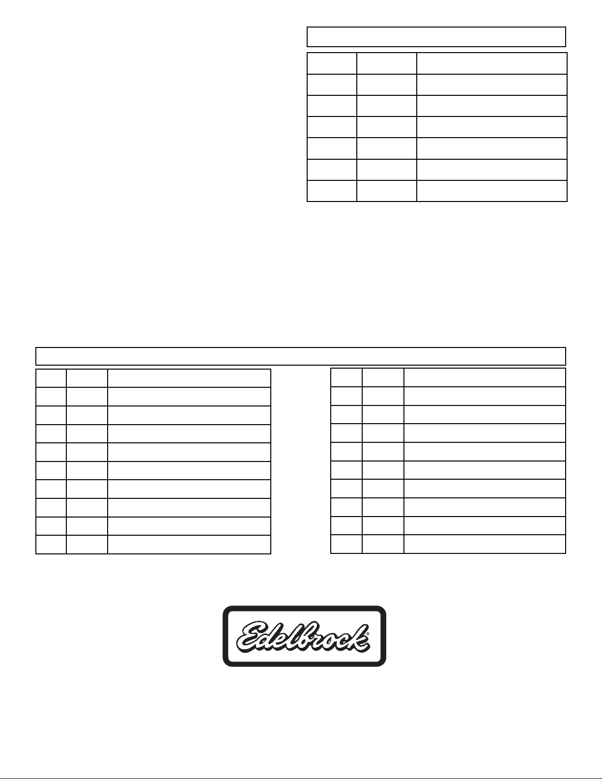
KIT CONTENTS
Edelbrock Corporation, 2700 California St., Torrance, CA 90503
Toll-Free Tech Line: 1-800-416-8628
Office: 310-781-2222
E-Mail: Edelbrock@Edelbrock.com
Qty. Part # Description
❑ 1 25-9808 Header, Left Side
❑ 1 25-9809 Header, Right Side
❑ 2 25-9222 Merge Collector
❑ 1 25-9814 Collector Extension (Left)
❑ 1 25-9815 Collector Extension (Right)
❑ 1 22-6590 Installation Kit
Qty. Part # Description
❑ 2 24-9716 A.I.R. Adapters
❑ 11 36-0710 Header Bolts
❑ 1 36-2860 C/B Bolt 3/8 - 16 x 2-1/4” (for port flange)
❑ 2 52-9710 O2 Sensor Bungs
❑ 2 54-6590 Port Flange Gaskets
❑ 3 56-6569 Heat Sleeves
❑ 4 60-8541 Hex Nut; 5/16”
❑ 4 68-6550 Hex Cap Screw; 5/16”
❑ 2 78-2004 Tie Wraps
Qty. Part # Description
❑ 1 79-9534 Spacer Tube
❑ 2 79-9749 Evac. Tubes
❑ 8 79-9750 Collector Tabs
❑ 1 79-9841 A.I.R. Sub-Assembly
❑ 2 79-9842 A.I.R. Sub-Assembly
❑ 1 79-9888 EGR Sub-Assembly
❑ 8 82-3600 Washer (AN); 5/16”
❑ 12 82-5590 Lock Washers; 3/8”
❑ 12 82-7231 Hardened Washers; 3/8”
#22-6590 - Installation Kit
3. From under vehicle, work header up on to bolt.
Install remaining header bolts and washers.
4. Re-install engine support bracket and engine
mount.
5. Lower engine and install engine mount bolt.
6. Install oil pressure sensor.
7. Re-install steering coupler shaft.
8. Slide steering rack back into location and re-install
and torque steering rack bolts to factory
specifications.
Right Side
1. Install one header bolt, lock washer, and hardened
washer with port gasket into front bolt hole on right
side of engine.
2. Working header up from under vehicle slip on to
bolt installed in Step 1. Install remaining bolts, and
washers.
3. Tighten header bolts from the center out.
4. Install spark plugs and wires.
5. Install starter.
6. Install alternator and support bracket.
 Loading...