

Page 1
INSTALLATION INSTRUCTIONS
Ford 351W Victor EFI Intake Manifold
• Please study these instructions carefully before installing your new intake manifold. If you have any questions or
problems, please call our Technical Hotline at: 1-800-416-8628, 7:00 am – 5:00 pm, Pacific Standard Time, Monday
through Friday or e-mail us at edelbrock@edelbrock.com.
8* - ¼-20 x 1 ¼” stainless socket cap screw 1*- 3/16 - 3/16 - 3/16 vacuum tee fitting
4* - 5/16 -18 x 1 ¼” flange head bolts 1* - 1/8 pipe x 3/8 dia. straight hose fitting
2* - 5/16-18 x 5” flange head bolts 1* - 1/8 pipe x 3/16 dia. Hose
2* - 5/16-18 x 5 ¼” flange head bolts 1* - 3/8 pipe to 3/8 hose fitting
1 - Ford Victor 5.0 throttle bracket 1* - 3/8 pipe male to 3/8 pipe female 90° fitting
1 - base to upper gasket 1* - 10” length of 5/32” dia. vacuum line
1* - plenum cover gasket 2* - 3/8-18 pipe plug
2 ft - ¼” I.D. push lock fuel line 2* - 1/8 pipe plug
* 3887 only
§ DESCRIPTION: The Edelbrock Victor EFI intake manifold is designed for ultra high performance and racing 351W
based engines. Its large short runners are compatible with stroker applications up to 427 C.I. There are no provisions for
EGR or the PCV system. The fuel injector angles and hold-down posts are positioned to work with stock Mustang 5.0l
left and right fuel rails or aftermarket equivalents (aftermarket fuel rails and an adjustable regulator are recommended for
high {400+} horsepower applications). Push-Lok fuel line has been included to make longer fuel rail crossovers.
§ POWER PACKAGE: This manifold is designed for use with either our Victor Jr. (PN 7716) or Victor (PN 7721) cylinder
heads. The manifold port exits are sized to fit within the Fel-Pro 1262 gasket. We recommend our 75mm Throttle Body
PN 3826.
§ ACCESSORIES: Edelbrock offers a full line of chrome and Elite Series Valve covers for SB Ford engines. We also have
water pumps that will increase coolant flow and block pressure in your engine. There are three different models for SB
Fords. See our catalog for details. To order a catalog, call (800) FUN-TEAM.
§ EGR SYSTEMS: This manifold is intended for non-emission, non-EGR, racing applications. Because the EGR plate is
not used the throttle body is relocated. A new throttle cable bracket is included with this kit.
INSTALLATION INSTRUCTIONS
Catalog #3886 Base only & # 3887 Complete
Kit Contents
1) To use standard Mustang 5.0l fuel rails: Cut and remove the stock crossover tubes. Assemble the fuel rails onto the
manifold. Lubricate one end of the supplied Push-Lok hose with a small amount of lubricant (silicon, spray lube or
white grease). Push the hose over the barbs until it stops against the collar. No clamp is necessary. Now determine
the length necessary to reach the opposite rail, cut the hose, lubricate and install. The front crossover tube requires
more planning because of the close proximity of the manifold, the fuel rail ends, and the distributor. We suggest you
fit it on the engine.
2) We recommend the Fel-Pro Printoseal #1262 int ake gasket. For best results, port match the manifold to your heads.
3) Fully clean all traces of old gasket material and sealant from all of sealing surfaces. Apply Edelbrock Gasgacinch to
both the head intake flange and back of gasket. Let dry and install gasket to head.
4) Do not use cork or rubber end seals. Use “sensor safe” silicone sealer instead. Apply a ¼” high bead across each
block end seal surface, overlapping the intake gasket at the four corners. This method will eliminate end seal
slippage and deterioration.
4) For ease of installation and a cleaner look, we recommend using Edelbrock Manifold Bolt and Washer Kit #8524.
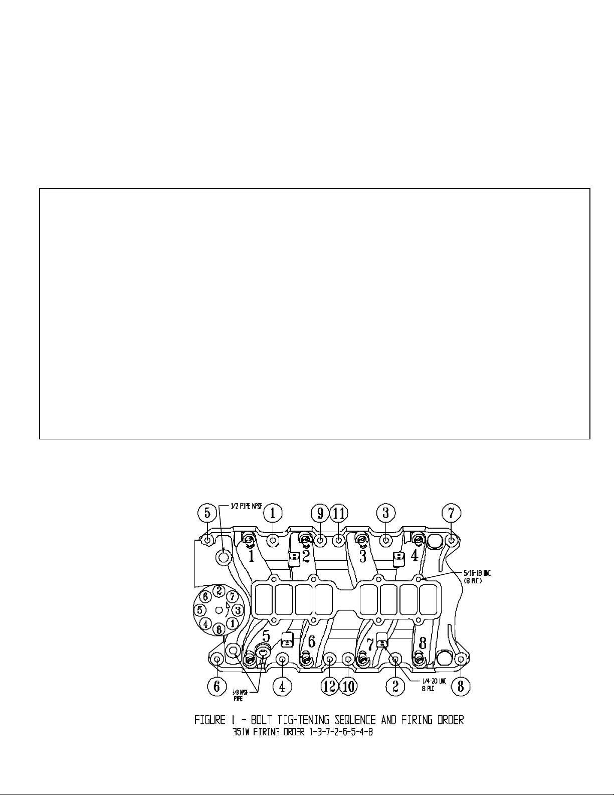
5) The Edelbrock throttle bracket substitutes for the stock EGR plate and throttle bracket. Place it underneath the two
right rear manifold bolts (# 3 & #7 in Figure 1). Some valve covers require the throttle bracket to be trimmed or
spaced up to fit.
6) Manifold Torque: See Figure 1. On early model iron heads, there is no support underneath manifold boltholes
circled 5, 6, 7, and 8. These bolts need to be hand-tightened with a short box end wrench being very careful not to
damage the manifold. Torque all other bolts in the sequence to 15-18 ft -lbs.
7) The stock Mustang heater tube assembly will interfere with the Victor EFI throttle bracket and cable arrangement. If
a heater unit is required, re-route your heater lines with hoses and eliminate the metal tubes.
Page 2
rings.
8) To smooth the crossover, we have eliminated the stock vacuum tree. Install the 3/8 NPT 90° elbow and the 3/8 NPT
to hose fitting in the boss on the back of the plenum. Install the 1/8 NPT to 3/16” hose next to it. Use the vacuum
tubing and the “T” fitting to signal the fuel pressure regulator and the MAP sensor from this source.
9) Install the upper manifold and gasket using the bolts supplied in the kit. The tall bosses that are closest to the
crossover take a slightly longer bolt than the outside holes. The gasket will seal dry, but if you pan to take the upper
on and off frequently, apply it with a light coat of white grease and you can get several uses out of it. Replacement
upper to lower and plenum cover gaskets are available a set (PN 7232).
10) NOTE: When installing the throttle cable, the #4 injector will need to be rotated for clearance.
11) If your vehicle is equipped with an automatic transmission, you must adjust the T.V. (throttle valve) cable. Refer to
your throttle body instructions for this procedure.
12) A re-torque of the manifold bolts is recommended (especially the upper to lower) after several operation cycles. Re-
torque when the engine is cold.
O.E. FUEL LINE REMOVAL AND INSTALLATION
CAUTION: Fuel system is under pressure. Pressure must be released before servicing fuel system components.
1. Remove fuel cap to release fuel tank pressure. Using EFI pressure gauge (T80L-9974-B), release fuel
pressure from fuel pressure relief on fuel rail.
2. Before disconnecting fuel lines, disconnect negative battery cable. To disconnect fuel lines, remove
retaining clip from outside of fuel line coupling.
3. Use Spring Lock Coupling Remover (D87L-9280-A) for 3/8” line or (9D87L-9280-B) for ½” line. Install
spring lock coupling remover on fuel line coupling so it enters cage opening.
4. Push spring lock coupling remover into cage opening to release female fitting from garter spring. Pull
couplings apart. Remove spring lock coupling remover.
5. To install fuel lines, install new O-rings on fuel lines. Use only specified fuel resistant brown OBefore installing, lightly coat O-rings with clean engine oil. Clean fittings and replace garter spring
(if necessary).
6. Fit female fitting to male fitting and push until garter spring snaps over flared end of female fitting. Ensure
lines are locked together and garter spring is over female fitting flared end.
7. Install retaining clip. Ensure horseshoe portion of clip is over coupling. DO NOT install retaining clip over
rubber fuel line. NOTE: Black retaining clip should be installed on fuel supply line and Gray clip on fuel
return line.
§ PLEASE complete and mail your warranty card. Be sure to write the model number of this product in the
“Part #________” space.
THANK YOU.
Brochure No. 63-0002
2001 Edelbrock Corp. Edelbrock Corporation •• 2700 California Street••Torrance, California 90503 Rev. 5/01
 Loading...