

Page 1
INSTALLATION INSTRUCTIONS
FOR 1996-2001 VIPER SHOCKS
Catalog #33505
§ Please read these instructions entirely before beginning. Proper installation is a must to realize the
maximum performance improvements.
IMPORTANT NOTES:
§ Upon initial inspection, some new shocks may have a small amount of oil in the area of the seal. This is a
normal occurrence following manufacture and does not indicate a problem with your shocks.
§ Any time you are working under a vehicle, be sure to use the proper jack stands and tire chocks to prevent
any shifting or slipping of the car. Never use a jack only to support the vehicle while changing shocks.
§ Inspect shock brackets or mounting points before installation to make sure they are not broken or bent.
§ Do not attempt to disassemble these shocks. Return damaged shocks to Edelbrock for any necessary
service or repairs.
INSTALLATION
Step 1 Support Viper by frame with jack stands or
on a lift.
Step 2 Remove all four w heels.
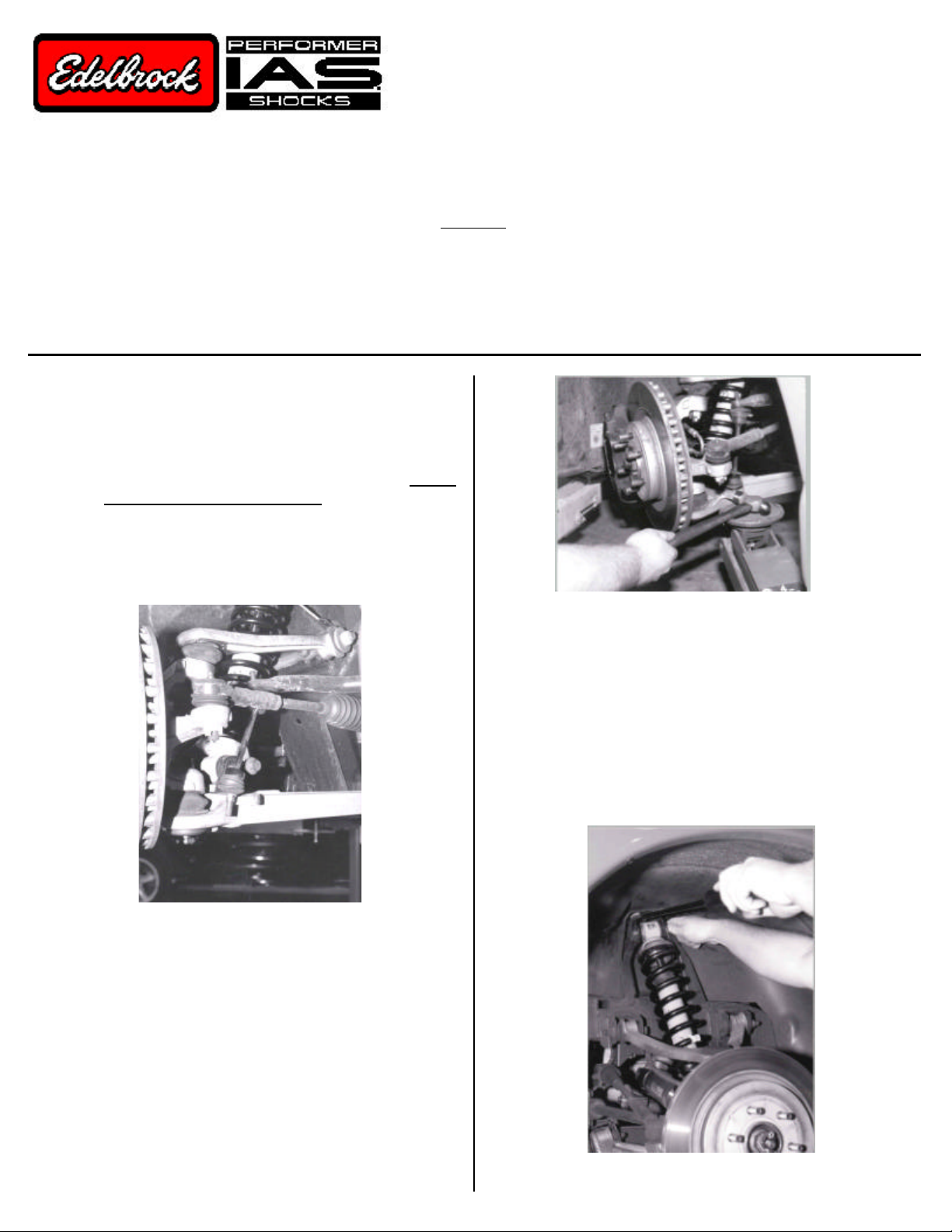
Step 3 Removal of front shocks:
3(a) Loosen upper and lower shock nuts, but do not
remove the bolts at this time. (see Fig. 1).
3(b) If the lower shock nut is to rear, the lower sway
bar end link must be removed in order for the
bolt to have enough clearance for removal.
(see Fig. 1).
Fig. 2
An aluminum block should be placed between arm and
hammer to minimize marking control arm, do not hammer
directly on the arm. It should only require a couple of
sharp taps with a hammer in order to pop from seat. Do
both left and right sides, and remove nuts.
3(d) Remove upper and lower bolts to remove
shock. It may need a little gentle persuasion
with a pry bar (see Fig. 3). Bolt should come
out by hand.
Fig. 1
3(c) Removal of lower sway bar endlink
If the tool for unseating the sway bar from the
lower control arm is not available, the following
procedure can be used. (The sway bar end
link is held in place with a tapered seat). In
order to remove:
3(c)1 Loosen lower sway bar end link nut, do
not remove completely
3(c)2 Place jack under the nut
3(c)3 Jack up and apply pressure
3(c)4 Tap control arm with hammer
(see Fig. 2).
3(e) Shock may be removed through the top.
Fig. 3
Page 2
Step 4 Removal of rear shock Step 6 Disassembly of rear coil springs from shock
4(a) Loosen upper and lower nuts.
4(b) In order to remove bolts, they may need a little
gentle persuasion with a pry bar. Bolt should
come out by hand (see Fig. 3).
4(c) Shock will now come out through the top.
6(a) Compress coil spring (see Fig. 6).
6(b) Move bump rubber down in order to remove
spring seat retainer (see Fig. 6).
6(c) Release coil spring compressor carefully.
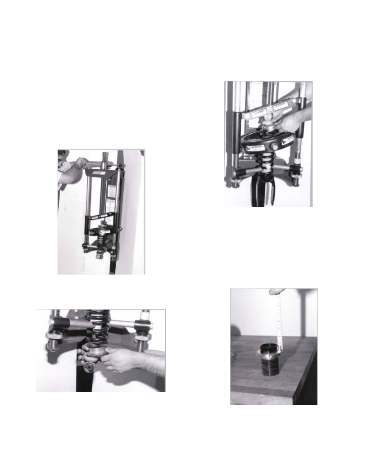
Step 5 Disassembly of front coil springs from
shocks
A coil spring compressor is required to remove the
springs from shocks. All proper safety precautions must
be followed. Consult spring compressor manufacturer
recommended instructions before starting.
5(a) Compress coil spring (see Fig. 4).
Fig. 4
5(b) Move bump rubber up shaft in order to remove
spring seat retainer (see Fig. 5).
Fig. 6
Step 7 Assembly of IAS shocks (Note: Apply anti-
seize compound to threaded collars)
7(a) Adjust all four threaded spring collars
(see Fig. 7).
2 front topped out
2 rear = 5/8” from top of threaded
collar.
Fig. 5
5(c) Release coil spring compressor carefully.
Fig. 7
Page 3
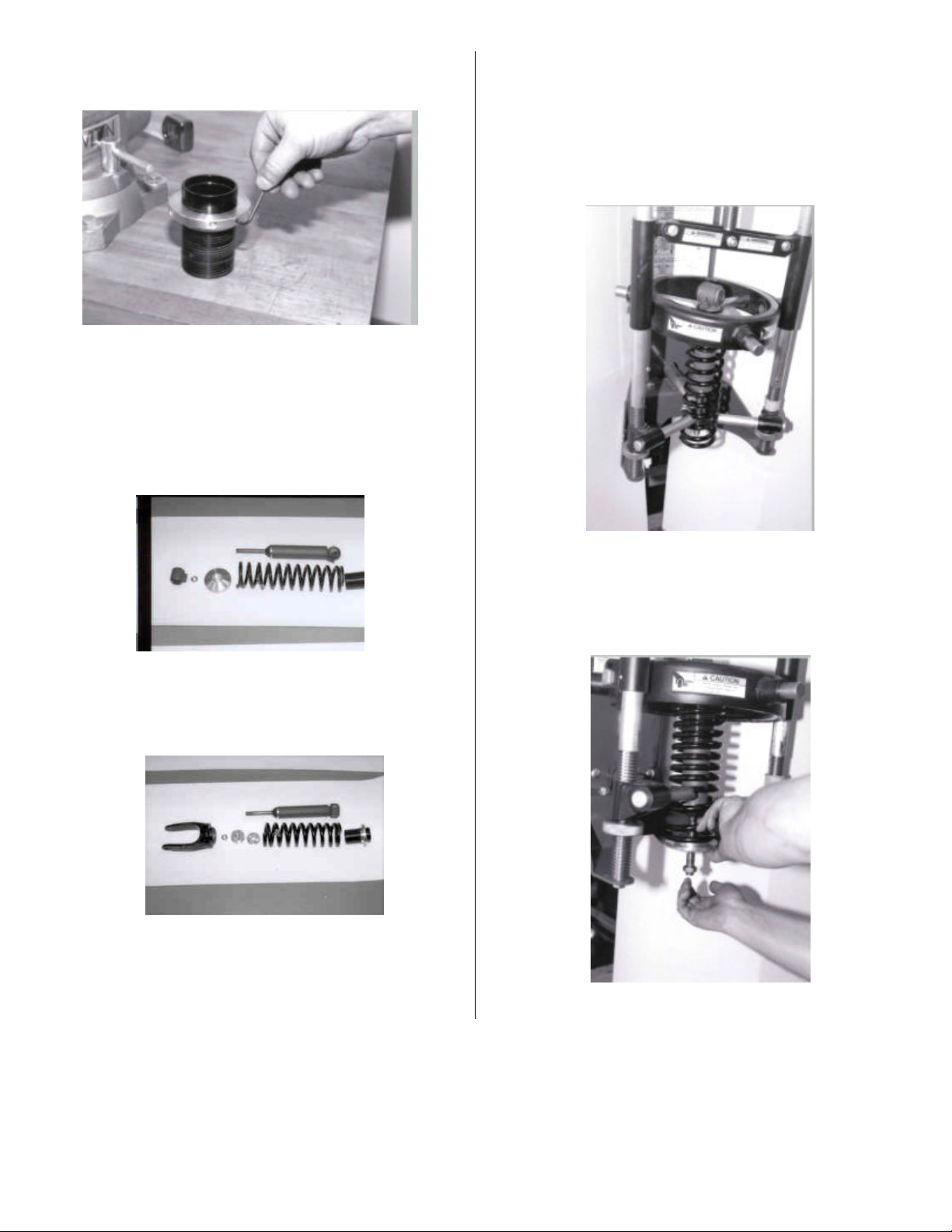
7(b) Install and tighten allen set screw with 1/8 allen
wrench (see Fig. 8).
Step 8 Assembly of Front shocks
8(a) Insert coil spring with flat ground end against
threaded collar seat .
8(b) Put shock and coil spring in spring
compressor (see Fig. 11).
Fig. 8
7(c ) Slide threaded collar onto shock. It should
seat against snap ring. Front shocks are
easily identified by short threads on the piston
rod (see Fig. 9).
Fig. 9
The rears have long threads on Piston rod
(see Fig. 10).
Fig. 11
8(c) Compress coil spring until lower seat has
enough clearance to install lower seat and
9/16 jamb nut (see Fig. 12).
Fig. 10
Fig. 12
Page 4

Screw jamb nut by hand until it hard stops at end of
threads (see Fig. 13).
Step 9 Rear IAS shocks
IAS shock reuses the O.E.M. large black clevis mount
and must be unscrewed from the shock body.
9(a) Mount clevis in vice with soft jaws, aluminum
preferred as not to mark up the clevis.
9(b) Using supplied crowfoot wrench (see Fig. 16)
Fig. 13
8(d) Apply Loctite to threads, screw rod end on by
hand until it hard stops, tighten jamb nut against
rod end with 1” wrench on rod end using a 7/8”
crowfoot wrench torque nut to 70 ft lbs.
(see Fig. 14).
Fig. 14
8(e) After removing from spring compressor, make
sure spring fits correctly in lower spring pocket.
(see Fig. 15)
Fig. 15
Fig. 16
(Top photo – spanner wrench )
(Bottom photo – crowfoot wrench)
loosen shock body from clevis with ½” drive breaker
bar and crowfoot wrench (see Fig. 17).
Fig. 17
(From the factory, the shock body was torqued to the
clevis with Loctite, so it will require a bit of effort to
remove).
9(c ) Once the clevis and shock body are apart, the
threads need to be cleaned to remove any
grease, Loctite or dirt (use brake cleaner or
parts wash), etc.
9(d) Install the threaded collar on to shock seating it
against snap ring on the IAS shock
(see Fig. 18).
9(e) Install short clevis adapter jamb nut with holes
up towards shock body (see Fig. 18).
9(f) Screw clevis adapter nut on piston rod by hand
until threads stop, install 9/16 jamb nut with
Loctite (see Fig. 18).
Page 5

9(g) Clamp supplied spanner wrench (see Fig. 16) in
vise (see Fig. 18) to support threaded adapter
torque nut to 75 ft lbs. with 7/8 socket.
9(i) Assemble shock by screwing the adapter with
Loctite applied into clevis (see Fig. 20),
Fig. 18
9(h) Clamp clevis in vise. Install spring on clevis
spring seat (see Fig. 19).
Fig. 19
Fig. 20
screw the adapter in cl evis until it bottoms (see
Fig. 21), torque to 70 ft lbs. using same spanner
wrench (see Fig. 16).
Fig. 21
9(j) Screw the thin threaded adapter jamb nut with
Loctite applied until it bottoms and torque to 70- ft
lbs. with spanner wrench.
Page 6

Step 10 Installing IAS shocks
Reinstallation is reverse of removal.
10(a) Both front and rear may require a little gentle
persuasion with a long pry bar to push control
arms down in order to install bolts (see Fig. 22
and Fig. 22a). Do not torque nuts at this time.
Front lower bolts may be installed with nuts to
the front. This will make it easier for
reassembly.
10(b) Front sway bar end links may now be
reinstalled. Install both left and right at the
same time. After both sides are in position, the
end link to control arm nuts can be torqued to
16 ft lbs.
10(c) Important: After all four shocks are installed,
place jack or jack stand under control arm –
support vehicle to load suspension at ride
height and torque bolts to:
Front (upper and lower) 80-100 ft. lbs.
Rear (upper) 80-100 ft. lbs.
Rear (lower) 130 ft. lbs.
This must be done to pre-load bushing for their
proper position in order for safe and proper
handling. This is a very important step.
10(d) Install and torque wheels to 90 ft. lbs. After
5-10 miles, re-torque wheels to 90 ft. lbs.
Fig. 22
Fig. 22a
Parts List
Qty. Description Qty. Description
2 #33505 Front shock assemblies 1 Crowfoot wrench (for removal of shock from clevis)
2 #34505 Rear shock assemblies 1 Spanner wrench (for installing and torquing of rear
2 Rear rodend clevis adapters threaded clevis adapter and jamb nut)
2 Rear rodend clevis adapter locknuts 1 Loctite tube
4 Upper coilover spring perch 1 Anti-seize
4 Coilover threaded sleeves 1
Hardware kit
4 - set screws
4 - 9/16 jam nuts
Enjoy the improved ride and handling from your new Edelbrock IAS shocks.
Edelbrock Corporation
2700 California Street
Torrance, California 90503
Office (310) 781-2222
Fax (310) 320-1187
Toll-Free Tech Line (800) 416-8628
Tech E-mail: edelbrock@edelbrock.com
2001 Edelbrock Corporation
PN 84-8152
Revised 2/01
Page 7

INSTALLATION INSTRUCTION
PROOFING FORM
Date:
From:
To:
Part No./
Description:
PN 33505 – Shocks for 1996-2001 Viper
Reviewed by: Date
Reviewed by: Date
Reviewed by: Date
Approved by: Date
No. of copies to be printed:
Received by:
F0505D
2/20/01
Gary Nelson
Jack Mayberry
Date
 Loading...