

Page 1
Catalog #2925.
Rev. 5/07 - RS/mc
©2007 Edelbrock Corporation
Brochure #63-2925
Page 1 of 2
PLEASE study these instructions carefully before beginning this installation. Most installations can be accomplished with common tools and
procedures. However, you should be familiar with and comfortable working on your vehicle. If you do not feel comfortable performing this installation,
it is recommended to have the installation completed by a qualified mechanic. If you have any questions, please call our Technical Hotline at:
1-800-416-8628, 7:00 am - 5:00 pm, Pacific Standard Time, Monday through Friday or e-mail us at Edelbrock@Edelbrock.com
.
IMPORTANT NOTE: Proper installation is the responsibility of the installer. Improper installation
will void your warranty and may result in poor performance and engine or vehicle damage.
DESCRIPTION: The Super Victor Small Block Chevrolet intake manifold is designed for use on competition 302-400 C.I.D. small block Chevrolet
engines operating from 3500-8000 RPM. Features include 2.80 square inch cross section runners designed to match the “flat floor” entry of today’s
23° cylinder heads. It is designed for standard port location 23° Chevrolet cylinder heads. Runners should be port matched to your cylinder heads for
optimal performance.
NOTE: This manifold is designed for competition vehicles only! It is not intended to be used on the street as it does not have provisions for
chokes, emissions equipment, etc. Note that additional coolant outlets (3/8" NPT) are provided at the rear of manifold for custom cooling
system plumbing, if desired. IT IS THE RESPONSIBILITY OF THE END USER TO VERIFY CONFORMITY TO A PARTICULAR RACING
ASSOCIATION’S RULES REGARDING MANIFOLD DIMENSIONS, FITMENT TO A TEMPLATE, ETC.
SUPER VICTOR SMALL BLOCK CHEVROLET
For 302-400 c.i.d. Chevrolet V8
Catalog #2925
INSTALLATION INSTRUCTIONS
EGR SYSTEMS—This manifold will not accept stock EGR (exhaust gas
recirculation) equipment. EGR systems are used on some 1972 and later
model vehicles and only in some states. Check local laws for
requirements.
INTAKE GASKETS—Manifold runners as cast fit well with Edebrock
#7201 intake gaskets. If additional port enlargement is desired, use FelPro #1206 intake gasket or equivalent.
CARBURETOR RECOMMENDATIONS—Use appropriate 4150 series
racing carburetor. See Edelbrock catalog or visit www.Edelbrock.com for
available fuel lines, accesories, and linkage adapters if necessary for
your application. For assistance please contact our Technical Hotline
listed above.
CARBURETOR SPACERS—Both engine dynamometer and in-car tests
have shown additional torque is available by use of a one-inch high open
(not 4-hole) carburetor spacer (#8710 or #8720) on the Super Victor
manifold. This normally requires slight re-calibration of the carburetor
since small losses of fuel signal cause the engine to run somewhat
leaner than without the spacer. A simple jet change is typically all that
needs to be done. If a spread-bore carburetor is to be used, a 1-inch
adapter will provide the necessary height increase (if hood space is
available).
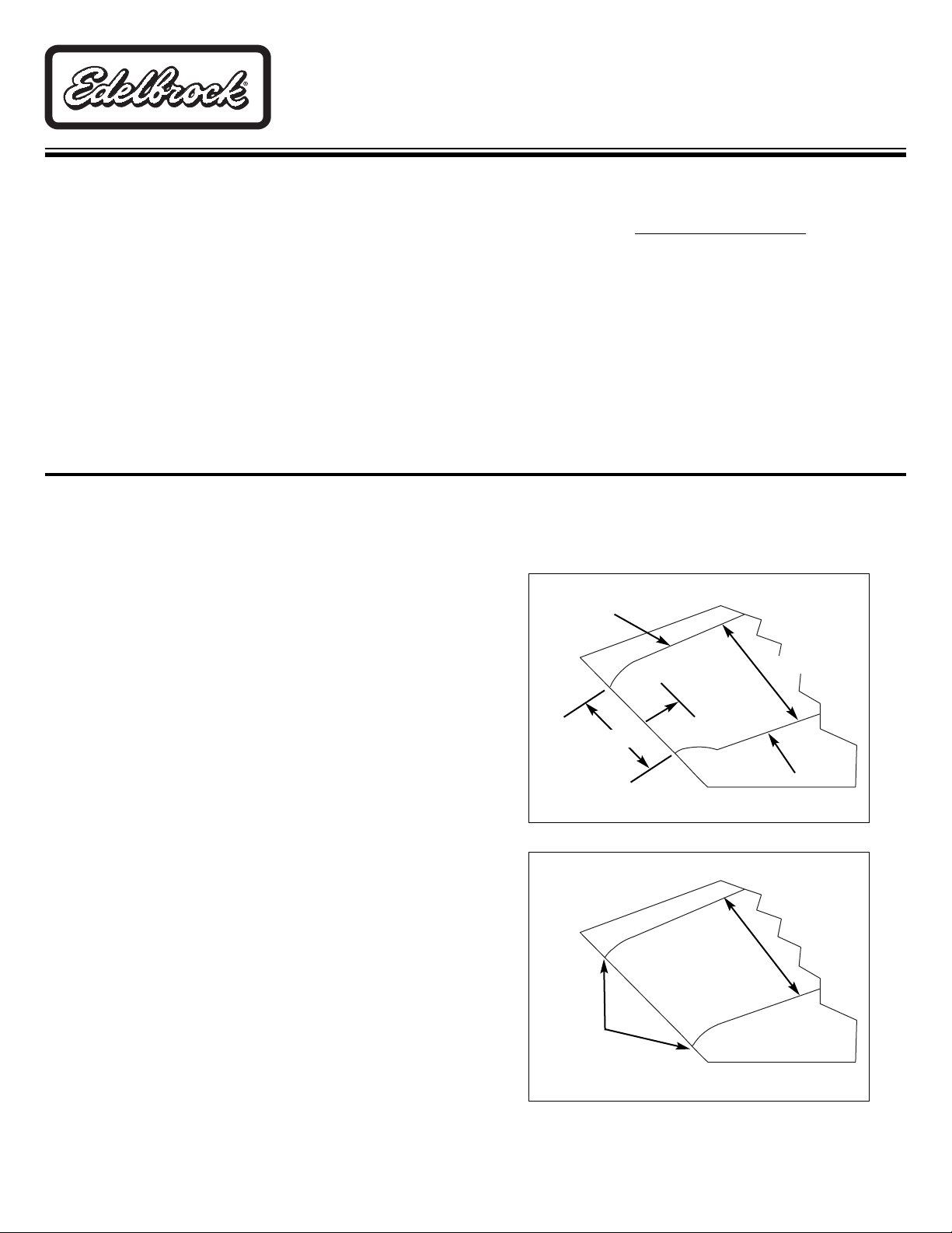
PORT MATCH—Each intake runner should be matched to the cylinder
head port size on all four sides of runner exit. This would be the floor,
roof and each sidewall per the included illustration. Any sharp edges left
from port runner enlargement should be radius-blended to prevent high
rpm air/fuel separation at the cylinder head. This does not include
removing material on floor back into the runner from the exit end. It is
just a port match. Due to the as-cast size of the Victor Jr. manifold
runners, very small amounts of material need to be removed to match
ports. No other modification or material removal is necessary. Refer to
illustrations for floor radius. Hard-roll polishing is acceptable, but
substantial amounts of grinding away of manifold material can impair its
performance by substantially upsetting air/fuel distribution among
cylinders.
Figure 1
Stock Height
1”-2” Back
From Exit
Roof
Floor
Stock Height
Stock Height
Matched
to Head
Figure 2
Page 2
Catalog #2925.
Rev. 5/07 - RS/mc
©2007 Edelbrock Corporation
Brochure #63-2925
Page 2 of 2
INSTALLATION NOTES—The area of the manifold above each pair of runners has been machined to clear the valve covers when used with most
aftermarket (aluminum) cylinder heads, such as Edelbrock Victor Jr. heads #7700. Can be used as reference point for port match. Additional manifoldto-valve cover clearance will be required when manifold is used on most stock type (cast iron) heads. This may be accomplished by using extra-thick
valve cover gaskets or by trimming the manifold or valve covers as required. The manifold bolt holes have been slotted .100" up and down to allow
the manifold to work with competition engines which may have had the block or heads machined.
NOTE: With some cast iron cylinder heads, the bottom of the slot may not be sealed by the gasket, resulting in an oil leak from the valley area.
If this occurs, apply a small amount of RTV silicone sealant into the affected area to seal the leak.
1. Make sure the cylinder head intake flanges and the engine block end seal surfaces are fully cleaned prior to installation.
2. Apply Edelbrock Gasgacinch sealant PN 9300 to both cylinder head flanges and to the cylinder head side of the gaskets, allow to air dry,
and attach the intake gaskets.
3. Do not use cork or rubber end seals. Use RTV silicone sealer instead. Apply a ¼" high bead across each block end seal surface,
overlapping the intake gasket at the four corners. This method will eliminate end seal slippage.
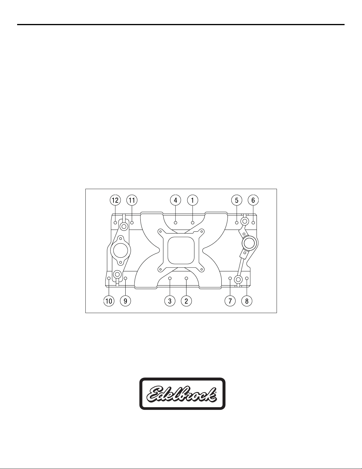
4. Install the intake manifold and hold-down bolts. Torque the manifold bolts to 25 ft/lbs in small, even steps, following the factory
recommended torque sequence
(See Figure 3)
. If you cannot fit a torque wrench on some of the bolts, use a small box end wrench to
avoid over tightening.
NOTE: Check bolt clearance near the water crossover. Minimal clearancing of the water crossover may be required for socket
or wrench clearance with a standard hex bolt.
Edelbrock Corporation • 2700 California St. • Torrance, CA 90503
Tech-Line: 1-800-416-8628 • E-Mail: Edelbrock@Edelbrock.com
INSTALLATION PROCEDURE
Figure 3 - Manifold Bolt Torque Sequence
Torque Bolts to 25 ft/lbs.
 Loading...