

Page 1
Victor Jr. LS1 EFI Intake Manifold
for GM 5.7L LS1 Style V8 Engines
Catalog #29085 & #29086
INSTALLATION INSTRUCTIONS
PLEASE study these instructions carefully before installing your new Intake Manifold. If you have any questions or problems, do not
hesitate to contact our Technical Hotline at: 1-800-416-8628, from 7am-5pm PST, Mon-Fri, or via e-mail at:
Edelbrock@Edelbrock.com . Please fill out and mail your warranty card. Remember to include the model number of this product
in the “Part #____” space. Thank you.
CAUTION: Make sure the vehicle’s battery has been disconnected and that the vehicle is supported on a level surface to prevent
any possibility of the vehicle moving during the installation procedure.
• MANIFOLD: The single plane Victor Jr. LS1 Intake Manifold is intended for racing and engine swap applications. Part
# 29086 includes fuel rails. A separate fuel rail kit may also be purchased under part # 3638.
• EGR SYSTEM: This manifold has no provision for EGR (exhaust gas recirculation) equipment. EGR systems are used on most
1972 and later model vehicles, up to certain GVWs. Check local laws for requirements. This manifold is not considered to be a
direct replacement part.
• ACCESSORIES & INSTALLATION ITEMS: Major recommendations are listed below. However, because this manifold system is
intended for engine swaps into a variety of vehicles, some customization may be required.
ITEM NOTES PART NUMBER AND DESCRIPTION
Throttle Body Standard Square-Bore Style Base P/N 3878 - With standard GM/Delphi IAC
P/N 38783 - With Mototron/Hitachi Linear Style IAC
Fuel Rail Kit Stock Injector Angles P/N 3638 - Includes Hold Down Brackets
Headers 1-3/4” - 1-7/8” Step, Victor Series Various. See Catalog For Details
Camshaft Developed for Carbureted Applications P/N 2215 - 220° Int./224° Exh. @ .050”, .510” Valve Lift
P/N 2216 - 230° Int./237° Exh. @ .050”, .540” Valve Lift
• KIT CONTENTS: 29085 and 29086
QTY. Description
❑ 1 Intake Manifold
❑ 1 MAP Sensor Bracket (For LS1 Style Sensor)
❑ 1 1/8”NPT to ¼” Hose Fitting (For MAP)
❑ .75 ft ¼” I.D. Vacuum Hose (For MAP)
❑ 2 Cable Bracket (Large Opening)
❑ 2 Cable Bracket (Small Opening)
❑ 1 GEN III EFIThrottle Bracket Base
❑ 4 6mm x 1.0 x 12mm Serrated Flange Hex Bolt
❑ 4 6mm x 1.0 Serrated Flange Hex Nut
❑ 10 6mm x 50mm Hex Head Capscrew
❑ 10 ¼” AN Washer
29086 Additionally Includes:
QTY. Description
❑ 2 Machined Fuel Rail
❑ 4 Fuel Rail Stand
❑ 4 ¼”-20 x 1-¼” Hex Head Bolt
❑ 4 ¼”-20 Hex Nut
❑ 8 ¼” AN Washer
❑ 4 ¼” Lock Washer
❑ 4 ¼”-20 x ½” Socket Head Bolt
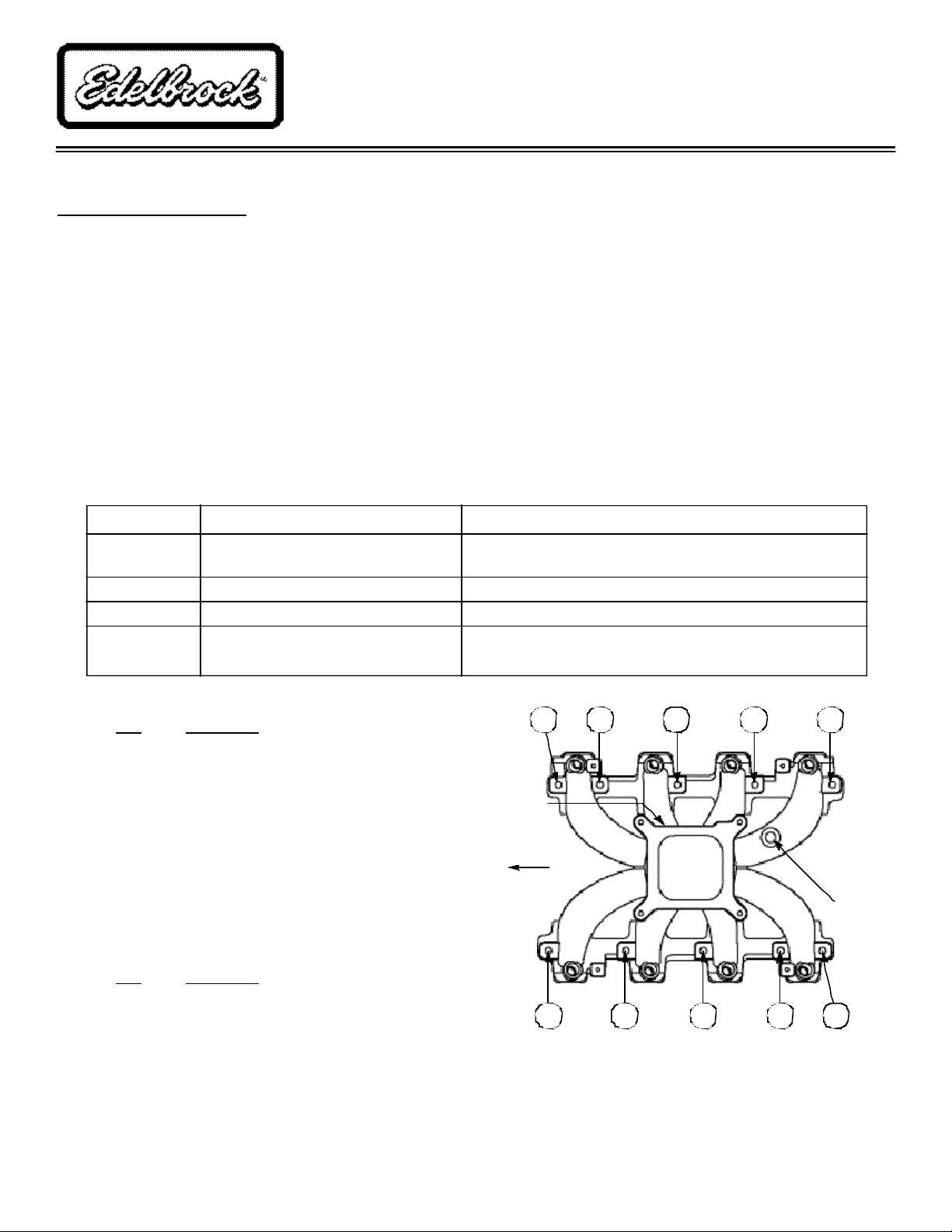
10 4 1 5 8
1/8” NPT
Front
Figure 1 - Intake Manifold Tightening Sequence
3/8” NPT
93267
Catalog #29085, #29086
Rev. 5/05 - RS/mc
Page 1 of 2
©2005 Edelbrock Corporation
Brochure #63-0341
Page 2

• INSTALLATION PROCEDURE:
1. (Note: Use only original equipment (GM P/N 12533587) O-Ring type
gaskets when installing this intake manifold). No gasket sealer is
required when using the OEM type gaskets. Using the supplied 6mm
x 50mm hex head bolts and 1/4” AN washers, mount the manifold to
the engine. The Gen III throttle bracket mounts under the two left side
rear intake manifold bolts. Following the torque sequence in
Figure 1, torque all manifold bolts to 11 ft/lbs.
2. Select the appropriate cable brackets for your application (large or
small opening brackets) and attach them to the GEN III throttle
bracket base with the appropriate number of 6mm x 1.0 x 12mm
serrated flange hex bolts. (Note: In our retrofit of the LS1 into a
1974 Camaro, using a TH400R automatic transmission, we only
Figure 2 - Throttle Cable Bracket
needed one of the small opening cable brackets for the throttle cable,
since a kickdown cable is not used. See Figure 2 for example.)
• FUEL RAIL KIT (29086 only): Install fuel rail kit using the included stands and 1/4”-20 nuts and bolts. For 29085, a fuel rail
kit may be purchased separately under part #3638. Fuel rail kit 3638 may also be used in custom applications where manifold
29085 is not being used.
• INJECTOR SELECTION AND INSTALLATION: It is important to select the appropriate electronic injectors for optimum
performance. The injectors must not only match the fuel demands of an engine, but they must also match the electronic
capability of the engine control unit (ECU). When installing the injectors onto the manifold, make sure that the O-rings of the
injectors create a complete seal to prevent any air or fuel leaks. The same precaution should be applied when assembling the
injectors to the fuel rails. Use assembly lube on O-rings when installing injectors. Brake assembly lube works well.
• FINAL CHECKS: After assembling the injectors, fuel rails, support brackets, throttle body, spacer (if needed), gaskets, and air
cleaner, check the following:
❑ Have an assistant depress and release the gas pedal. Check for full open throttle at the throttle body. Check for any possible
interference of the throttle with other components. Make sure the throttle can return without binding.
❑ Check the fit of each injector. They should be able to rotate freely. The O-rings should be fully inside their respective bores.
❑ Activate the fuel pump and fully check the system for any leaks prior to starting the engine.
Catalog #29085, #29086
Rev. 5/05 - RS/mc
Edelbrock Corporation • 2700 California St. • Torrance, CA 90503
Tech-Line: 800-416-8628 • E-Mail: Edelbrock@Edelbrock.com
©2005 Edelbrock Corporation
Page 2 of 2
Brochure #63-0341
 Loading...