

Page 1
Catalog #2801, 2802, 2803, 2804, 2805, 2806
Rev. 6/07 - RS/mc 1 of 2
©2007 Edelbrock Corporation
Brochure #63-0339
BIG VICTOR (SPREAD-PORT) INTAKE MANIFOLDS
For Standard and Tall Deck Big Block Chevrolet
V8s Using Spread-Port Style Cylinder Heads
Catalog #s 2801, 2802, 2803, 2804, 2805, 2806
INSTALLATION INSTRUCTIONS
PLEASE study these instructions carefully before beginning this installation. Most installations can be accomplished with common tools and
procedures. However, you should be familiar with and comfortable working on your vehicle. If you do not feel comfortable performing this installation,
it is recommended to have the installation completed by a qualified mechanic. If you have any questions, please call our Technical Hotline at:
1-800-416-8628, 7:00 am - 5:00 pm, Pacific Standard Time, Monday through Friday or e-mail us at Edelbrock@Edelbrock.com.
IMPORTANT NOTE: Proper installation is the responsibility of the installer. Improper installation
will void your warranty and may result in poor performance and engine or vehicle damage.
PLEASE complete and mail your warranty card. Be sure to write the model number of this product in the "Part #____" space. THANK YOU.
DESCRIPTION: Big Victor intake manifolds are designed for big block Chevrolet engines using spread-port style cylinder heads such as Edelbrock Big
Victor Dart Big Chief, Profiler Raptor, or Brodix Big Duke cylinder heads (See
Applications
below for specific descriptions). These intake manifolds are
designed for competition applications only. They are not intended to be used on the street as they do not have provisions for chokes, emission
components,
etc.
NOTE: It is the responsibility of the end user to verify conformity to a particular racing
association’s rules regarding manifold dimensions, fitment to a template, etc.
• APPLICATIONS:
2801/2802: Manifolds are designed for use with Dart Big Chief or Profiler Raptor
Cylinder heads. #2801 fits standard 9.8” deck height blocks, while
#2802 fits tall 10.2” deck height blocks. These manifolds are
recommended for use on engines over 600 C.I.D.
2803/2804: #2803 fits standard deck height blocks and #2804 fits tall deck
height blocks (using Dart Big Chief, or Brodix Big Duke Heads).
These manifolds are designed with a smaller runner cross section
for engines under 590 C.I.D., or 600+ C.I.D. engines designed for
peak power under 6500 rpm (such as marine applications).
2805/2806: Manifolds are designed for 600 C.I.D. or larger engines, using
Brodix Big Duke cylinder heads They are similar to #2801/2802,
except they feature runner exits more closely matched to the Brodix
cylinder head. #2805 is designed for standard deck height blocks,
and #2806 is designed for tall deck height blocks.
• CARBURETOR RECOMMENDATIONS: Appropriate 4500 series racing carburetor.
• CARBURETOR SPACERS: Testing has shown, in certain applications, additional
torque is available with the use of a one-inch thick, open (not 4-hole) carburetor
spacer on Big Victor intake manifolds. Edelbrock spacer #8718 offers a closer
match to the semi-cloverleaf opening in the Victor Spread-Port manifold,and #8717
is a standard open, non-cloverleaf spacer.
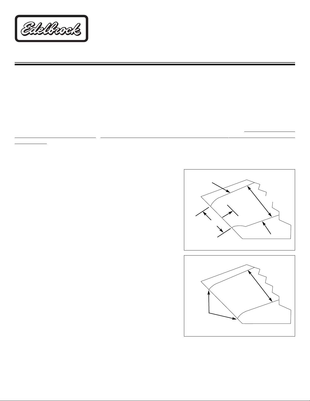
• PORT MATCH: Port matching of each intake runner to the cylinder head port size
on all four sides of the runner exit is REQUIRED for best results. This would be the
floor, roof, and each sidewall per the included illustrations
(See Figure 1 and
Figure 2)
. Port locations and porting technique will vary by manufacturer. More
grinding may be necessary on the roof of the port than on the floor, or vice versa, depending on these variables. Any sharp edges left from port
runner enlargement should be radius blended to prevent high rpm air/fuel separation at the cylinder head. Due to the as-cast size of the Victor
Spread-Port manifold runners, very small amounts of material need to be removed to match the ports. No other modification or material removal
is necessary. Refer to illustrations for floor radius. Hard-roll polishing is acceptable, but substantial amounts of grinding away of manifold material
can impair its performance by greatly upsetting air/fuel distribution among cylinders.
Stock Height
Matched
to Head
Figure 1
Figure 2
Stock Height
1”-2” Back
From Exit
Roof
Floor
Stock Height
®
Page 2

Catalog #2801, 2802, 2803, 2804, 2805, 2806
Rev. 6/07 - RS/mc 2 of 2
©2007 Edelbrock Corporation
Brochure #63-0339
1. Make sure the cylinder head intake flanges and the engine block end seal surfaces are fully cleaned prior to installation.
2. Apply Edelbrock Gasgacinch sealant PN 9300 to both cylinder head flanges and to the cylinder head side of the gaskets, allow to air dry,
and attach the intake gaskets.
3. Do not use cork or rubber end seals. Use RTV silicone sealer instead. Apply a ¼" high bead across each block end seal surface,
overlapping the intake gasket at the four corners. This method will eliminate end seal slippage.
4. Install the intake manifold and hold-down bolts. Torque the manifold bolts to 25 ft/lbs in small, even steps, following the factory
recommended torque sequence
(See Figure 3)
. If you cannot fit a torque wrench on some of the bolts, use a small box end wrench
to avoid over tightening.
NOTE: Check bolt clearance near the water crossover. Minimal clearancing of the water crossover may be required for socket
or wrench clearance with a standard hex bolt.
Edelbrock Corporation • 2700 California St. • Torrance, CA 90503
Tech-Line: 1-800-416-8628 • E-Mail: Edelbrock@Edelbrock.com
INSTALLATION PROCEDURE
Figure 3 - Manifold Bolt Torque Sequence
Torque Bolts to 25 ft/lbs.
• INTAKE GASKETS: Manifold runners as cast, will fit well with Fel-Pro #1298 intake gaskets. The gasket match to the ports and bolt holes may
vary, and should be adjusted for best fit to the ports.
• END SEAL CLEARANCE: Due to varying deck heights and/or valley widths, either from decking the block or milling the cylinder heads, the end
seal clearance should be checked. Lay the manifold on the engine with gaskets in place, and measure the clearance. There should be a minimum
of .060” between the block surface and the end seal surface of the manifold. You may need to machine the manifold flanges or end seal surface
to achieve optimum clearance.
 Loading...