

Page 1

©2007 Edelbrock Corporation
Brochure #63-16041 of 6
Catalog #1604, 1606, 1607, 1624, 16041 & 16061
Rev. 3/07 - RS/mc
PERFORMER RPM™ CNC MACHINED CYLINDER HEADS
For 1984 & Later Harley-Davidson
®
Evolution®“Big Twin” Engines
Catalog #1604, 1606, 1607, 1624, 16041 & 16061
INSTALLATION INSTRUCTIONS
PLEASE study these instructions carefully before beginning this installation. Most installations can be accomplished with common tools and
procedures. However, you should be familiar with and comfortable working on your vehicle. If you do not feel comfortable performing this installation,
it is recommended to have the installation completed by a qualified mechanic. If you have any questions, please call our Technical Hotline at:
1-800-416-8628, 7:00 am - 5:00 pm, Pacific Standard Time, Monday through Friday or e-mail us at Edelbrock@Edelbrock.com
. If your question
is motorcycle carburetor-related, please call our Edelbrock Motorcycle Carburetor division at 1-877-888-7504, Ext. 2.
IMPORTANT NOTE: Proper installation is the responsibility of the installer. Improper installation
will void your warranty and may result in poor performance and engine or vehicle damage.
DESCRIPTION: The Edelbrock Performer RPM™ Cylinder Heads are designed to provide increased performance in the idle to 6000+ RPM range, in
1984 and later, 80-inch and larger, Evo Big Twin engines. They feature a CNC-machined, rectangular intake port to provide a noticeable increase in
air flow. The intake port is also raised .125" to help increase the velocity of the incoming air for more power. Edelbrock intake manifolds must
be used with these heads due to the unique port shape (see application chart below). The dual-quench combustion chamber features a
revolutionary new design that promotes a better mix and more efficient combustion. The CNC-machined, “D” shaped exhaust port provides a larger
area for increased flow, and is designed to create a mis-match between the exhaust pipe and the exit to reduce power-robbing exhaust reversion.
Performer RPM™ heads #1604, 1606, 1607, 1624, 16041, & 16061 fit 1984 and later Evolution
®
"Big Twin" engines. Performer RPM™ cylinder heads
are assembled with stainless steel valves (1.940" intake and 1.625" exhaust), ductile iron valve seats and guides, 1.460" O.D. heavy-duty valve
springs, teflon valve stem seals, and machined valve spring retainers and locks. The increased valve sizes require the use of aftermarket or modified
pistons. In 80-inch Evo engines, we recommend using Edelbrock/JE Sportsman Pistons, which match the uniquely shaped combustion chambers of
the Performer RPM cylinder heads. Other engine sizes require modified stock, or other aftermarket pistons.
INTAKE MANIFOLD APPLICATION CHART - Performer™ Cylinder Heads
3-Piece 3-Piece 3-Piece S&S
Cyl. Length
S&S Kit Flange Intake Spigot Intake “G”
Intake
stock (80") -- #1671 #1670 #1669
stock 89" #1671 #1670 #1669
-.050" 93" #1676 #1677 #1683
-.175" 88" #3031 #3030 #3032
+.015" 96" #1671 #1670 #1669
+.075" 98" #1674 #1675 #1684
IMPORTANT NOTES BEFORE BEGINNING INSTALLATION
• It is recommended that the installation of Performer RPM cylinder heads be performed by a qualified engine builder with experience in high
performance or racing modifications to Harley-Davidson®engines.
• If you are using any cam other Edelbrock Performer RPM cam #1740, it is mandatory that valve-to-valve clearance is checked to
determine if these heads are compatible with the camshaft you intend to run. See Page 2.
REPLACEMENT ITEMS
The following replacement items are available separately:
Exhaust Seat . . . . . . . . . . . . . . . . . . . . . . . . . . . . . . .#1643
Intake Seat . . . . . . . . . . . . . . . . . . . . . . . . . . . . . . . . .#1644
Exhaust Valve . . . . . . . . . . . . . . . . . . . . . . . . . . . . . . .#1645
Intake Valve . . . . . . . . . . . . . . . . . . . . . . . . . . . . . . . .#1646
Exhaust Guide . . . . . . . . . . . . . . . . . . . . . . . . . . . . . .#1647
Intake Guide . . . . . . . . . . . . . . . . . . . . . . . . . . . . . . . .#1648
Page 2
©2007 Edelbrock Corporation
Brochure #63-16042 of 6
Catalog #1604, 1606, 1607, 1624, 16041 & 16061
Rev. 3/07 - RS/mc
1. Before installing heads on engine, remove valve springs, retainers
and locks from one head. Leave the valve seals on to hold the
valves in position during the clearance check.
2. Use a 6" caliper to measure valve tip height from the valve spring
pocket.
3. Find the cam manufacturer’s "Valve lift at Top Dead Center" specs
and subtract this dimension from the valve tip height you measured
in step 2.
4. Using the calipers to check the new valve tip height, open the valve
by the amount calculated in step 3.
5. Repeat this process for the other valve. Note that intake and
exhaust "Valve lift at Top Dead Center" dimentions are usually
different.
6. With both intake and exhaust valves open to the correct
specifications, use a .060" feeler gage to check clearance between
the valve heads. If less than .060" clearance exists, you run the risk
of valves hitting during engine operation, voiding any warranty on
these cylinder heads. If there is less than .060" clearance, select
another cam for your engine.
CHECKING VALVE-TO-VALVE CLEARANCE
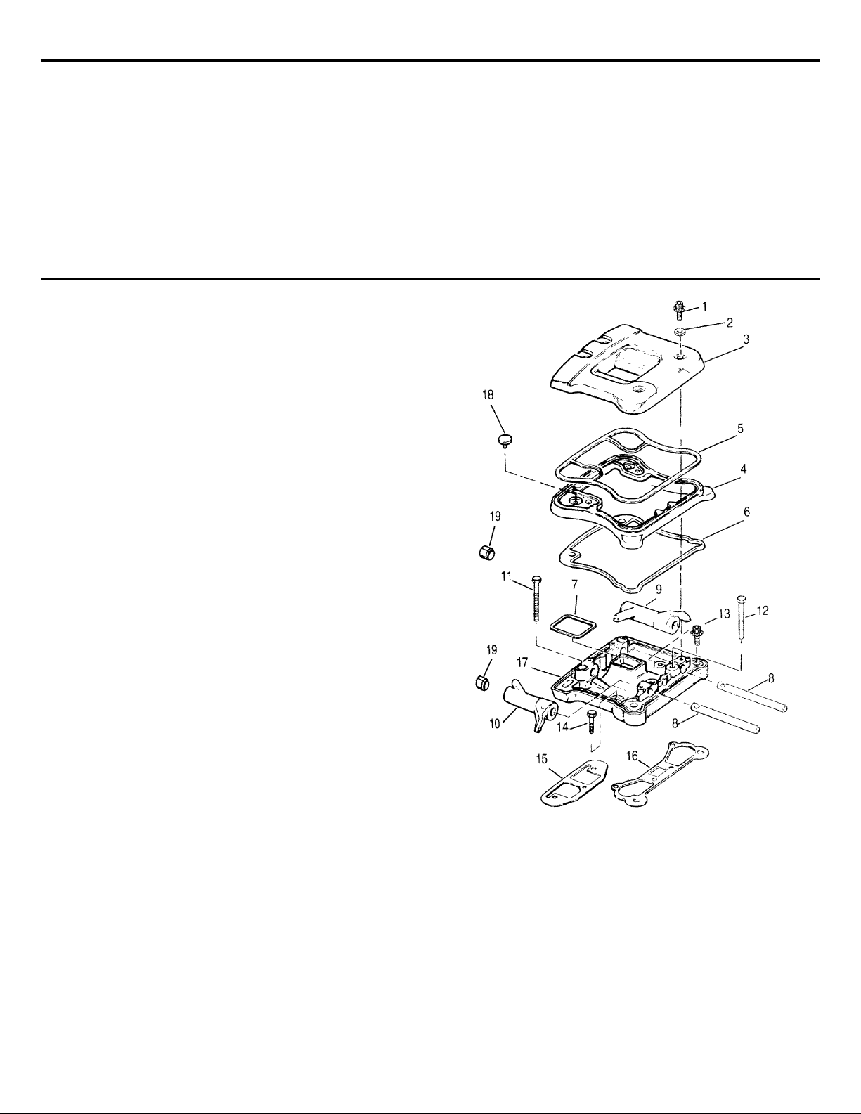
1. Bolt (4)
2. Seal (4)
3. Upper rocker arm cover
4. Middle rocker arm cover
5. Gasket
6. Gasket
7. Gasket
8. Rocker arm shaft (2)
9. Rocker arm
10. Rocker arm
DISASSEMBLY
11. Bolt and washer (2)
12. Bolt and washer (2)
13. Bolt and washer (3)
14. Bolt and washer (3)
15. Gasket
16. Gasket
17. Lower rocker arm cover
18. Umbrella valve
19. Rocker arm bushing (4)
WARNING
To avoid accidental start-up of vehicle and possible personal
injury, disconnect the battery cables (negative cable first) before
performing any of the following procedures.
1. Remove seat.
2. Remove instrument cover (FX/Softail and Dyna Glide models).
3. Drain fuel tank. Disconnect fuel line and plug end of fuel line with
5/16" bolt. For split tanks use a 1/4" bolt and rubber cap to plug
fuel line and opening. Disconnect any wires from tank. Remove fuel
tank.
WARNING
Gasoline is flammable and fumes are explosive. To
avoid possible personal injury, drain gasoline in well
ventilated area away from fire or flame. Drain
gasoline into approved gasoline container only.
NOTE: FX/Softail Models
An access hole has been provided through the frame to
remove the left rear rocker box bolt. A rolled up paper tube
should be inserted through the hole in the frame and around
the bolt head during removal, to prevent accidentally
dropping the bolt into the frame opening.
4. Remove upper cylinder head stabilizer from frame and cylinder head
bracket. Do not loosen stabilizer jam nuts.
5. On FXR model remove ignition switch.
6. Remove spark plugs.
7. On FLT models remove lower attaching bolts from right side
footboard.
8. Remove exhaust system.
9. Remove air cleaner cover, filter element and back plate.
10. Remove fuel and V.O.E.S. (Vacuum Operated Electric Switch) hoses
from carburetor.
11. Remove carburetor.
12. Remove intake manifold flange screws and remove intake manifold.
13. Support engine with small jack and piece of wood, then remove
large center bolt from front engine mount. On some bikes, it may be
necessary to remove ignition module first.
14. Remove bolt from outer end of front stabilizer.
15. Remove both front engine mount bolts and remove front engine
mounting plate with stabilizers.
16. Use the jack to raise and lower engine as needed for clearance.
Figure 1 - Rocker Arm Cover Assembly.
Page 3
©2007 Edelbrock Corporation
Brochure #63-16043 of 6
Catalog #1604, 1606, 1607, 1624, 16041 & 16061
Rev. 3/07 - RS/mc
REMOVE ROCKER ARM COVERS
1. Remove bolts (1) and seals (2)
(See Figure 1)
. Use a shortened
3/16" allen wrench.
2. Remove top (3) and middle (4) sections of rocker box. Remove
gaskets (5, 6, and 7) and discard.
3. Rotate the engine so both valves are closed on the head being
removed.
4. Remove the rocker arm retaining bolts (11) and washers nearest the
rocker arm shafts at the push rod end.
NOTE: Remove lower rocker boxes as an assembly then
disassemble if necessary.
5. Remove the push rods (1) and mark their location and orientation,
top and bottom
(See Figure 2)
.
6. Remove spring cap retainers (2) on push rod covers and remove
push rod covers and associated parts (3 through 11)
(See Figures
2 & 3)
.
CAUTION
All valve train components must be reinstalled in their
original positions. Remove Spring Cap Retainers.
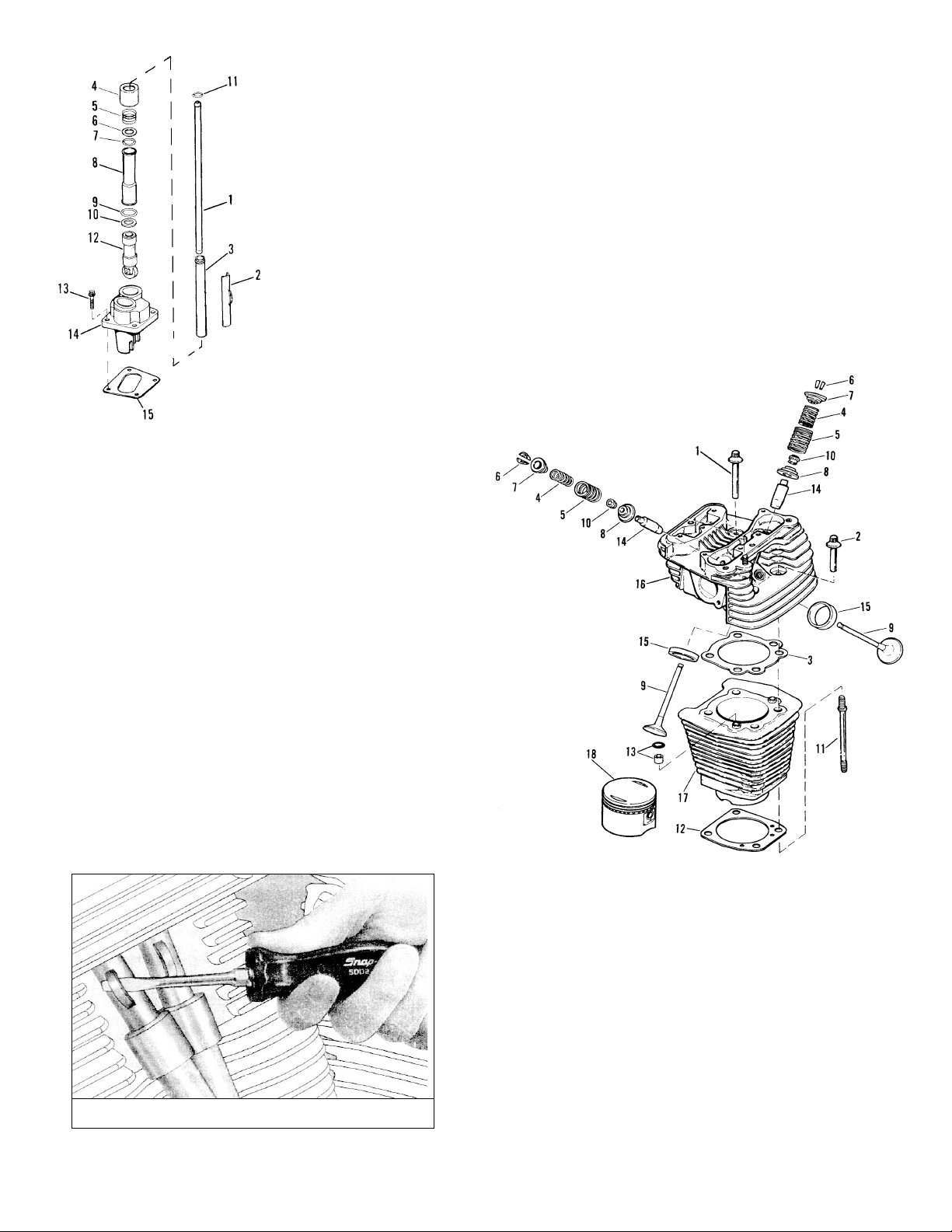
1. Push rod (2)
2. Spring cap retainer (2)
3. Upper push rod cover (2)
4. Spring cap (2)
5. Spring (2)
6. Spacer (2)
7. O-ring (2)
8. Lower push rod cover (2)
9. O-ring (2)
10. Spacer (2)
11. O-ring (2)
12. Tappet (2)
13. Bolt (4)
14. Lifter guide (2)
d15. Gasket (2)
Figure 2 - Pushrod and Cover Assembly
Figure 3 - Removing Spring Cap Retainers
7. Remove the remaining fasteners (12, 13 and 14) holding the lower
rocker arm cover (17) to the cylinder head
(See Figure 1)
.
8. Remove the lower rocker cover and gaskets (15 and 16).
9.
See Figure 4
. Loosen each head bolt (1, 2) 1/8 turn following the
cross pattern sequence shown in
Figure 9
CAUTION
Loosen head bolts gradually, in a cross pattern, to
prevent distorting the head, cylinder and crankcase
studs.
10. Continue loosening in 1/8 turn increments until bolts are loose.
11. Remove bolts.
12. Remove cylinder head and head gasket.
13. Repeat steps 1 through 14 for the other head.
NOTE: It may be necessary to raise or lower engine in frame
for clearance. Use small jack under engine.
1. Head bolt, long (2)
2. Head bolt, short (2)
3. Cylinder head gasket
4. Inner valve spring (2)
5. Outer valve spring (2)
6. Valve keeper (4)
7. Upper collar (2)
8. Lower collar (2)
9. Valve (1) intake, (1) exhaust
10. Valve stem seal (2)
11. Cylinder stud (4)
12. Cylinder base gasket
13. O-ring and insert (2)
14. Valve guide (2)
15. Valve seat (2)
16. Cylinder head (2)
17. Cylinder (2)
18. Piston
Figure 4 - Cylinder Head and Cylinder
Page 4
©2007 Edelbrock Corporation
Brochure #63-16044 of 6
Catalog #1604, 1606, 1607, 1624, 16041 & 16061
Rev. 3/07 - RS/mc
CYLINDER HEAD INSTALLATION
CAUTION
Install new O-rings over the cylinder dowels before
installing the head gasket. Install the O-rings first to
ensure alignment of the head gasket and prevent
gasket leaks.
CAUTION
Use only original equipment specification head bolts
and other hardware. All original hardware is
hardened grade 8 material, which is required for
proper performance of these parts.
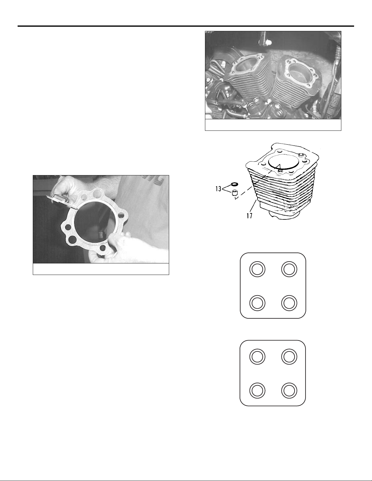
1. Be sure the gasket surfaces and stud holes are clean and dry
(See
Figure 6)
. Place new O-rings (13) on the cylinders and position the
head gaskets on the inserts (13)
(See Figure 7)
.
2. Dip the head bolt threads and bottom face of bolt head in oil; then
wipe off any excess. Install the head bolts (1 and 2, Figure 4) finger
tight.
HEAD GASKETS
You must use the correct head gaskets to achieve a 9.5:1
compression ratio for best power. Thicker gaskets will lower
compression and power, and thinner gaskets will raise compression
higher than advisable for use with today's unleaded pump gasoline.
1. Use Edelbrock gasket set #1640 for 1984-91 or #1641 for
1992 and later engines. This set includes the proper thickness
head gaskets (.045") and the special intake manifold gaskets
required for these cylinder heads.
2. You may use standard Harley-Davidson
®
head gaskets, if desired.
They vary in thickness, so it is advisable to measure your gasket
before use
(See Figure 5)
. Recommended thickness is .045".
CAUTION
If you use copper head gaskets, be aware that they
must be properly annealed prior to installation. Even
if gaskets were annealed when new, copper can reharden during storage. Failure to anneal before
installation may lead to head gasket failure.
INSTALLATION PROCEDURE
Figure 5 - Measuring Cylinder Head Gasket
Figure 7 - Cylinder O-Rings and Inserts
Figure 6 - Cleaning Gasket Surfaces
Figure 8 - Cylinder Head Bolt Torque Sequence
1
Front cylinder
2
2
Rear cylinder
1
3
4
4
3
Page 5
©2007 Edelbrock Corporation
Brochure #63-16045 of 6
Catalog #1604, 1606, 1607, 1624, 16041 & 16061
Rev. 3/07 - RS/mc
PUSH ROD INSTALLATION
1. Rotate the engine so that both lifters of the cylinder being serviced
are on the base circle (lowest position) of the camshaft.
NOTE: When using an aftermarket performance camshaft,
such as Performer RPM, which is dyno matched and
recommended for use with Performer RPM Cylyinder Heads,
you must use an adjustable pushrod kit such as Edelbrock
#1737. Refer to the instructions provided with your pushrod
kit for the proper valve adjustment procedure. Complete this
adjustment procedure BEFORE performing the final pushrod
installation.
2. Refer to
Figure 1
. Install push rod covers and associated parts,
using new O-rings. Install push rods.
NOTE: Be sure to use new O-rings on push rod tubes to
prevent leaks. Also check carefully to be certain old O-rings
were removed from push rod tubes and lifter bores.
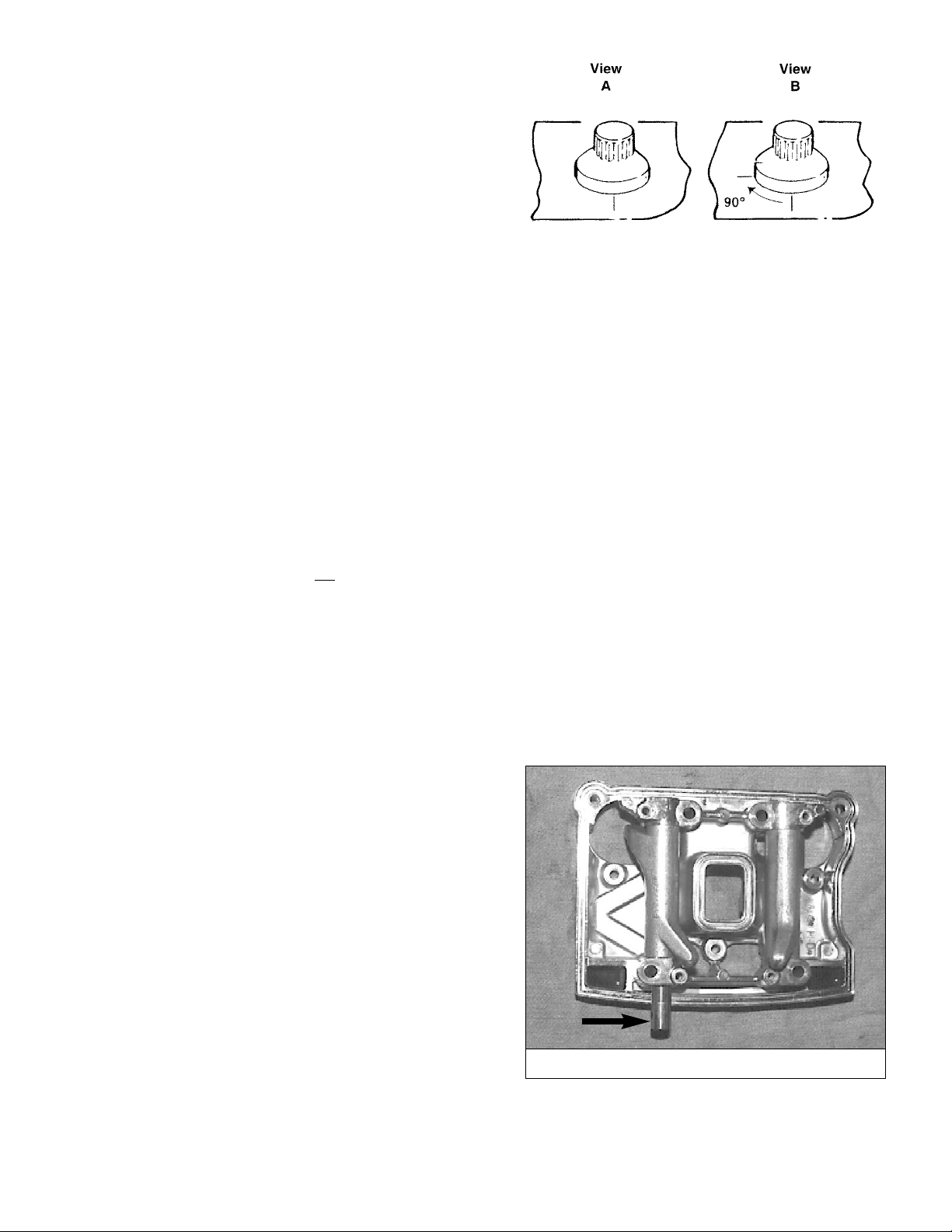
3. Install gaskets (15 and 16). Place lower rocker box assemblies (17;
with rocker arms and shafts) in position.
NOTE: Rocker arm shafts are notched to accept the rocker
arm retaining bolts. Align the notches with the bolt holes
before installing the bolts (See Figure 10).
3. Cylinder Head bolt torque sequence
(See Figure 8)
:
The procedure for tightening the head bolts is extremely critical; not
only to prevent gasket leaks, but to prevent stud failure and heads
and cylinders distortion.
CAUTION
Be sure you thoroughly clean and lubricate the
cylinder head bolts before tightening to the correct
torque. Friction because of dirt or grime will cause
the torque wrench readings to be incorrect. Clean
and lubricate the threads with engine oil and screw
the bolts onto the crankcase studs by hand to be sure
there is no friction.
A. Cylinder Head Torque Sequence for 1984-85 Models
CAUTION
Use only original equipment head bolts and studs
for your year vehicle to ensure proper torque and
head gasket life.
1.
See Figure 8
. With a torque wrench, start at the
cylinder head bolt numbered "1" and tighten to 7-9
ft./lbs. Then tighten "2", "3", and "4" in order to 7-9
ft./lbs.
2. Following the torque sequence, tighten each bolt to
15-17 ft./lbs.
3. Following the torque sequence, tighten each bolt to
24-26 ft./lbs.
CAUTION
The cylinder head bolts are not
to be checked
for tightness after final torquing at reassembly
is completed. Retightening the bolts to
specified torque at regular intervals will place
undue stress on bolts and bolt anchoring
threads.
B. Cylinder Head Torque Sequence for 1986-95 Models
CAUTION
Use only original equipment head bolts and studs
for your year vehicle to ensure proper torque and
head gasket life.
1.
See Figure 8
. With a torque wrench, start at the
cylinder head bolt numbered "1" and tighten to 7-9
ft./lbs. Then tighten "2", "3", and "4" in order to 7-9
ft./lbs.
2. Following the torque sequence, tighten each bolt to
12-14 ft./lbs.
3.
See Figure 9
. Mark a line on the cylinder head and
a corresponding line on the head of the cylinder head
bolt as shown in View A. Following the same
sequence 1, 2, 3, then 4, turn each bolt, one at a time
one quarter turn (90°) using the marks as a guide.
When marks are all positioned, as in View B, the
procedure is completed.
Figure 9 - Tightening 1986-1995 Head Bolts
Figure 10 - Rocker Arm Shaft Bolt Notches
Page 6

©2007 Edelbrock Corporation
Brochure #63-16046 of 6
Catalog #1604, 1606, 1607, 1624, 16041 & 16061
Rev. 3/07 - RS/mc
4. Install bolts and washers (11 and 12, 13 and 14). Slowly snug lower
rocker box fasteners in small increment (one at a time) in a cross
pattern. This will bleed the lifters. Check carefully as you go to be
certain push rods are still in their proper position in the rocker arm.
Tighten the 5/16" bolts (11, 12) to 15-18 ft./lbs. and tighten the 1/4"
bolts (13, 14) to 10-13 ft./lbs.
CAUTION
Do not turn engine over until push rods spin freely.
Damage could occur to valves.
4. Install the middle (4) and top (3) rocker arm covers, using new
gaskets and new fiber seals. The fiber seals must be under the steel
washers. Be sure the middle cover section is spaced evenly on all
sides before tightening the cover screws. Tighten the screws to 1013 ft./lbs. following a crisscross pattern. If a torque wrench cannot
be used, tighten securely by hand.
Edelbrock Corporation • 2700 California St. • Torrance, CA 90503
Tech-Line: 1-800-416-8628 • E-Mail: Edelbrock@Edelbrock.com
The words Evolution, Harley and Harley-Davidson are registered trademarks of
Harley-Davidson, Inc., Milwaukee, Wisconsin, USA and are used in this
instruction sheet for reference only.
Edelbrock is a registered trademark of Edelbrock Corp, Torrance, CA, USA.
5. Install the intake manifold according to the instructions provided
with the intake manifold.
6. Install the carburetor, V.O.E.S. and ignition components.
7. Reassemble all components removed during disassembly, connect
battery cables, and re-fuel gasoline tank.
8. To prevent discoloration when the engine reaches operating
temperature, carefully wipe off grease, fingerprints, stains, etc.,
from all chrome and polished surfaces with a lint-free cloth and
alcohol, Windex, etc., before starting engine.
 Loading...