

EDCO SS-26E User Manual
E-SS2636-DGE-I-1012
Operator’s Instruction Manual
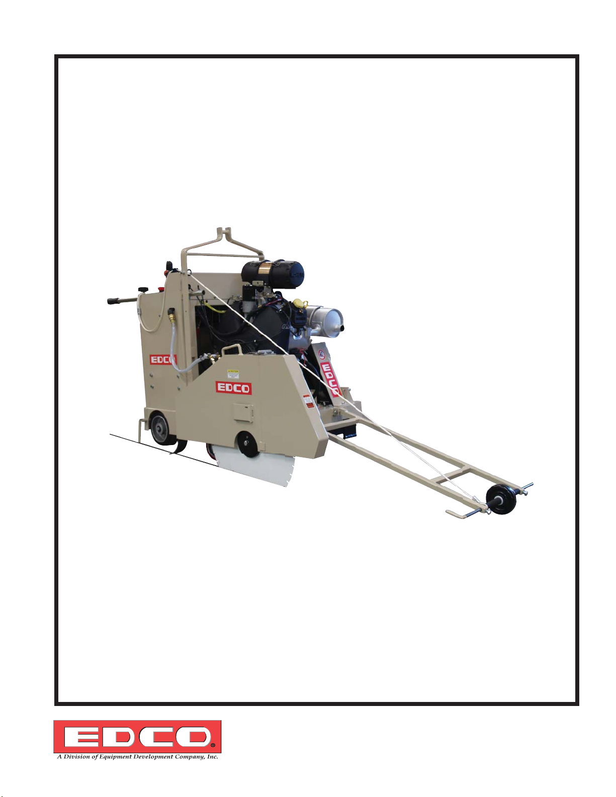
SS-26, SS-36 & SS-26E
SS-26 Shown
Self-Propelled
Concrete/Asphalt Saw
Diesel, Gasoline & Electric available
100 Thomas Johnson Drive, Frederick, MD 21702-4600 USA
Phone (301) 663-1600 • 1-800-638-3326
Fax (301) 663-1607 • 1-800-447-3326
Website: www.edcoinc.com • Email: sales@edcoinc.com
Printed in USA
TVW ©2012
Page 1
E-SS2636-DGE-I-1012
READ AND UNDERSTAND THE OPERATORS INSTRUCTION MANUAL THOROUGHLY
BEFORE ATTEMPTING TO OPERATE THIS EQUIPMENT.
Death or serious injury could occur if this machine is used improperly.
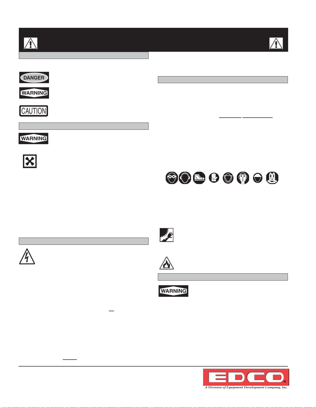
SAFETY
MESSAGES
• Safety Instructions are proceeded by a graphic alert symbol
of DANGER, WARNING, or CAUTION.
SAFETY MESSAGES
Indicates an imminent hazard which, if not
avoided, will result in death or serious injury.
Indicates an imminent hazard which, if not
avoided, can result in death or serious injury.
Indicates hazards which, if not avoided, could
result in serious injury and or damage to the
equipment.
GASOLINE/PROPANE POWERED EQUIPMENT
• Engine exhaust from this product contains
chemicals known to the State of California to
cause cancer, birth defects or other reproduc-
tive harm.
• Gasoline is extremely fl ammable and poisonous. It
should only be dispensed in well ventilated areas,
and with a cool engine.
• Small gasoline engines produce high concentrations of car-
bon monoxide (CO) example: a 5 HP 4 cycle engine opera tion in an enclosed 100,000 cu. ft. area with only one change
of air per hour is capable of providing deadly concentrations
of CO in less than fi fteen minutes. Five changes of air in the
same area will produce noxious fumes in less than 30 min utes. Gasoline or propane powered equipment should not be
used in enclosed or partially enclosed areas. Symptoms of
CO poisoning include, headache, nausea, weakness, dizzi ness, visual problems and loss of consciousness. If symp toms occur - get into fresh air and seek medical attention
immediately.
ELECTRICAL POWERED EQUIPMENT
Extreme care must be taken when operating electric
models with water present: Ensure power cord is properly grounded, is attached to a Ground-Fault-Interrupter
(GFI) outlet, and is undamaged.
• Check all electrical cables - be sure connections are tight and
cable is continuous and in good condition. Be sure cable is
correctly rated for both the operating current and voltage of
this equipment.
• Improper connection of the equipment-grounding conductor can
result in a risk of electric shock. Check with qualifi ed electri-
cian or service person if there is any doubt as to whether the
outlet is properly grounded. Adhere to all local codes and
ordinances.
• NOTE: In the event of a malfunction or breakdown, grounding
provides a path of least resistance for the electric current to
dissipate. The motor is equipped with a grounded plug and
must be connected to an outlet that is properly installed and
properly grounded. DO NOT modify the plug provided on the
motor. If the plug does not fi t the outlet have a qualifi ed electri-
cian install the proper receptacle.
• Switch motor OFF before disconnecting power.
• Do not disconnect power by pulling cord. T o disconnect, grasp
the plug, not the cord.
• Unplug power cord at the machine when not in use and before
servicing.
GENERAL INSTRUCTIONS
• Equipment should only be operated by trained personnel in
good physical condition and mental health (not fatigued). The
operator and maintenance personnel must be physically able
to handle the bulk weight and power of this equipment.
• This is a one person tool. Maintain a safe operating distance
to other personnel. It is the operators’ responsibility to keep
other people (workers, pedestrians, bystanders, etc.) away
during operation. Block off the work area in all directions with
roping, safety netting, etc. for a safe distance. Failure to do so
may result in others being injured by fl ying debris or exposing
them to harmful dust and noise.
• This equipment is intended for commercial use only.
• For the operator’s safety and the safety of others, always keep
all guards in place during operation.
• Never let equipment run unattended.
• Personal Protection Equipment and proper safety attire must
be worn when operating this machinery. The operator must
wear approved safety equipment appropriate for the job such
as hard hat and safety shoes when conditions require. Hearing protection MUST be used (operational noise levels of this
equipment may exceed 90db). Eye protection MUST be worn
at all times.
Keep body parts and loose clothing away from moving
parts. Failure to do so could result in dismemberment
or death.
• Do not modify the machine.
• Stop motor/engine when adjusting or servicing this equipment.
Maintain a safe operating distance from fl ammable
materials. Sparks from the cutting-action of this machine
can ignite fl ammable materials or vapors.
DUST WARNING
Some dust created by power sanding, sawing,
grinding, drilling, and other construction activities contains chemicals known to cause cancer,
birth defects, or other reproductive harm. Some
examples of these chemicals are:
• Lead from lead-based paints, and
• Crystalline silica from bricks and concrete and other
masonry products.
Your risk of exposure to these chemicals varies depending
on how often you do this type of work. To reduce your risk:
work in a well ventilated area, use a dust control system, such
as an industrial-style vacuum, and wear approved personal
safety equipment, such as a dust/particle respirator designed
to fi lter out microscopic particles.
Printed in USA
TVW
©2012
Page 2
100 Thomas Johnson Drive, Frederick, MD 21702-4600 USA
Phone (301) 663-1600 • 1-800-638-3326
Fax (301) 663-1607 • 1-800-447-3326
Website: www.edcoinc.com • Email: sales@edcoinc.com
E-SS2636-DGE-I-1012
Equipment Instruction Manual
EDCO Models SS26-38K, SS26-31D, SS26-15E & SS36-57D
Table of Contents
Section Page Number
Safety Messages.........................................................................................................2
Specifi cations..............................................................................................................3
Safety Guidelines........................................................................................................4
Operating Instructions..............................................................................................5-9
Tracking Adjustment....................................................................................................9
Maintenance.........................................................................................................11-16
Your Notes............................................................................................................17-18
Maintenance Schedule..............................................................................................19
Limited Equipment Warranty..........................................................................back page
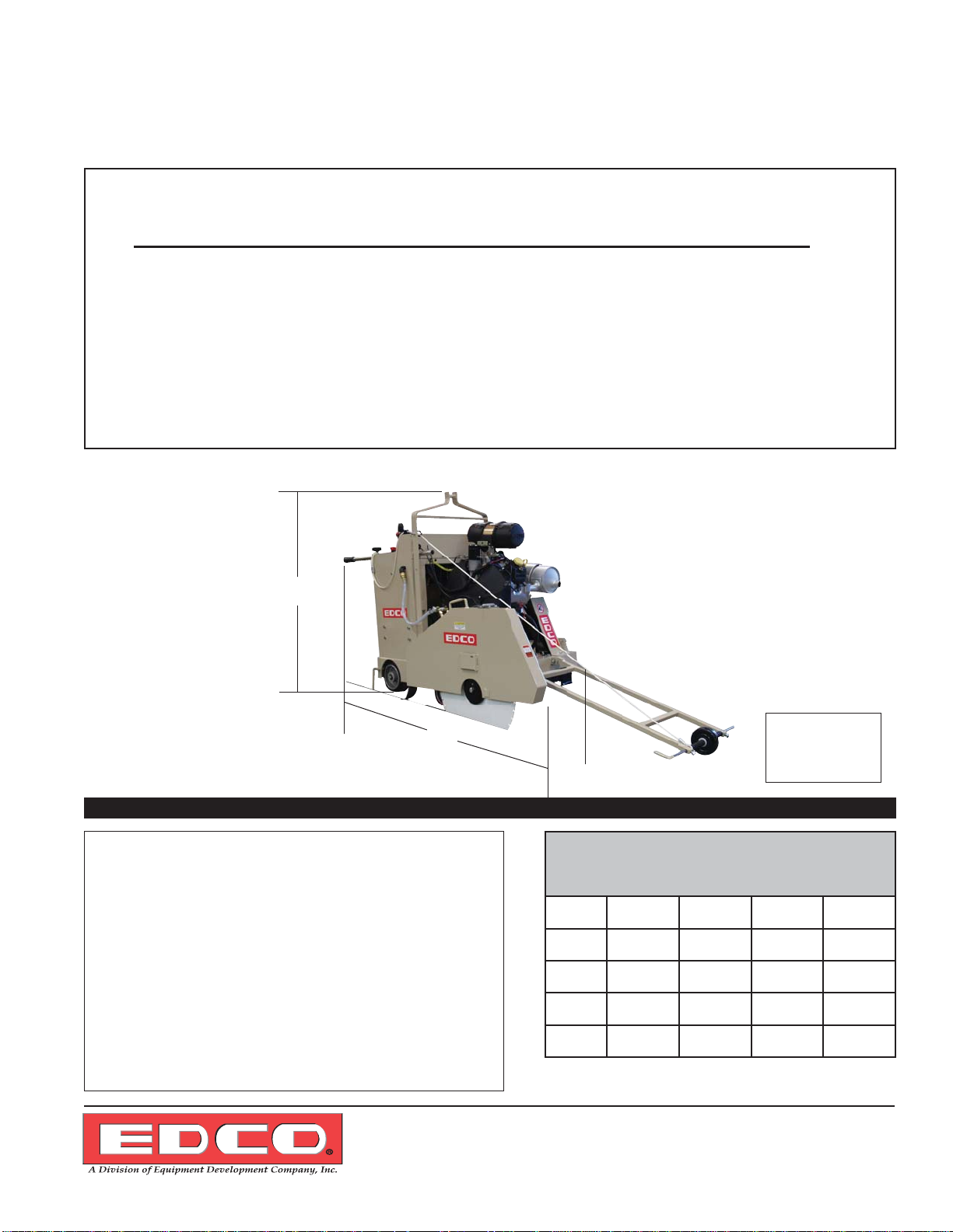
SS-26-38K Shown
Height
Length
Varies with type of bladeguard
Figure 1
HOW TO ORDER REPAIR PARTS
To insure product safety and reliability, always use genuine EDCO replacement parts when making repairs to the
equipment.
When ordering parts, please specify the MODEL and
SERIAL NUMBER of the machine as given on the NAMEPLATE. In addition, give part number, description and
quantity as listed on the parts list.
Please note: Due to improvements and changes in the
equipment the illustrations shown may be different from
the actual machine.
Toll Free: Voice 1-800-638-3326 • Fax 1-800-447-3326
Width
See Chart
Below
Specifi cations and dimensions are approximate
Model SS26-38K SS26-31D SS26-15E SS36-57D
Height
Width
Length
Weight
and subject to change
50 1/2”
128.27cm
32”
81.28cm
58”
147.32cm
995 lbs
451kg
160.02cm
145.41cm
63”
32”
81.28cm
57 1/4”
1225 lbs
556kg
50 1/2”
128.27cm
32”
81.28cm
58”
147.32cm
1094 lbs
451kg
154.94cm
91.44cm
175.26cm
1588 lbs
720kg
61”
36”
69”
100 Thomas Johnson Drive, Frederick, MD 21702-4600 USA
Phone (301) 663-1600 • 1-800-638-3326
Fax (301) 663-1607 • 1-800-447-3326
Website: www.edcoinc.com • Email: sales@edcoinc.com
Printed in USA
TVW ©2012
Page 3
E-SS2636-DGE-I-1012
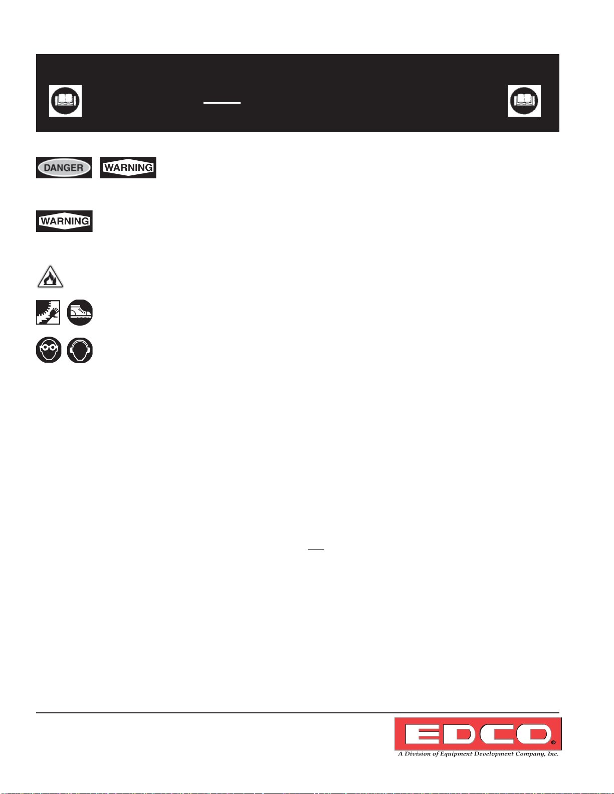
Read and understand the Operator’s Instruction Manual, the Rx for Concrete Saws,
and the Engine Manufacturer’s Owner’s Manual
before operating this equipment.
Death or serious injury can result if this machine is used improperly.
Safety Guidelines
Remove all rings, watches and jewelry prior to doing any work inside the console area.
Metallic jewelry could short out the positive lead on the battery or the hydraulic power unit and
cause severe bodily injury.
Maintain a safe operating distance from fl ammable materials. Sparks from the cutting-action of this saw can
ignite fl ammable materials or vapors.
Operator must wear appropriate clothing and footwear. Do not wear loose clothing or jewelry that can
get tangled or caught in moving parts.
Eye and ear protection must be worn at all times when this machine is in use. During normal use,
sound levels exceed 92dB. Use only ANSI approved safety glasses to help prevent eye injury. Normal, prescription eyeglasses have only impact resistant lenses; they are NOT safety glasses.
• Keep a safe operating distance from other personnel and never leave the machine running unattended.
• Maintain the machine in safe operating condition with all guards in place and secure, all mechanical fasteners
tight, all controls in working order and the saw confi gured for the job application.
• The SS26-38K, SS26-31D & SS36-57D are both designed to cut fl at, horizontal concrete or asphalt slabs using
diamond saw blades.
• The SS26-38K, SS26-31D & SS36-57D are to be operated by a single operator from a position at the rear of the
saw.
• Avoid deck inserts, pipes, columns, openings, electrical outlets, or any objects protruding from slab surface.
• Inspect the blades carefully before installing. Do not use any questionable blade since serious personal injury
and/or damage to property can result.
• Never operate this saw while under the infl uence of drugs, alcohol or when taking medications that impair the
senses or reactions, or when excessively tired or under stress.
• Be sure all safety decals on the machine can be clearly read and understood. Replace damaged or missing
decals immediately.
They are not given as substitutes for proper accident prevention and good judgement.
Printed in USA
TVW
©2012
Page 4
Safety warnings and guidelines do not by themselves eliminate danger.
100 Thomas Johnson Drive, Frederick, MD 21702-4600 USA
Phone (301) 663-1600 • 1-800-638-3326
Fax (301) 663-1607 • 1-800-447-3326
Website: www.edcoinc.com • Email: sales@edcoinc.com
E-SS2636-DGE-I-1012
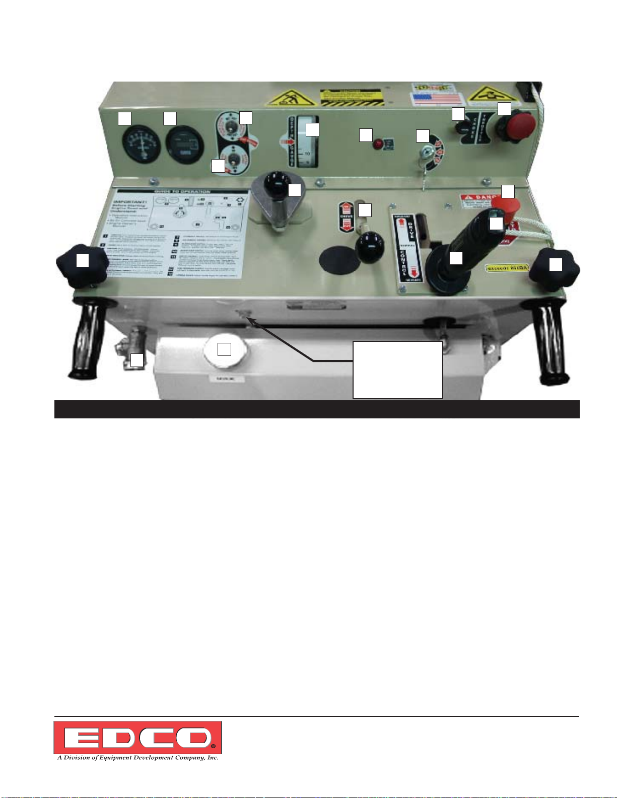
SS26-38K Gasoline Powered Operating Controls
10
1 2
14
6
15
5
4
16
7
8
3
9
17
11
13
12
DC Hydaulic
Power Unit mounted
inside compartment at
this location.
(See page 10)
10
Figure 3
SS26-38K Operator’s Console
1. Ammeter
2. Hour Meter
3. Cut Control
4. Depth Gauge
5. Blade Saver Switch
6. Water Pump Switch
7. Ignition Switch
8. Choke
9. Throttle
10. Handle Locks
11. Clutch
12. Drive Control Lever
13. Blade Lift/Lower Rocker Switch
14. Water Hook Up
15. Gasoline Fill Cap
16. Low Oil Indicator
17. Emergency Stop
NOTE: Due to design changes and advances in technology your machine may not look
exactly like machines illustrated in this manual. All controls function in the same manner.
100 Thomas Johnson Drive, Frederick, MD 21702-4600 USA
Phone (301) 663-1600 • 1-800-638-3326
Fax (301) 663-1607 • 1-800-447-3326
Website: www.edcoinc.com • Email: sales@edcoinc.com
Printed in USA
TVW ©2012
Page 5
E-SS2636-DGE-I-1012
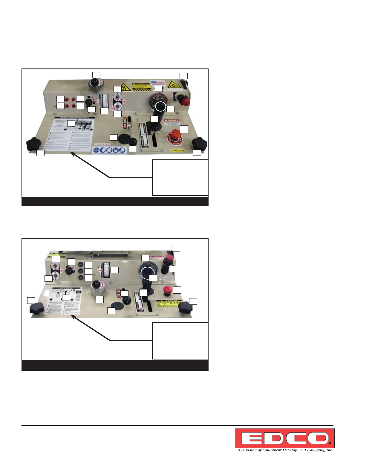
Diesel Powered Operating Controls
17
18
5
8
1
2
3
4
6
7
9
19
11
13
14
15
12
16
17
SS36-57D Operator’s Console
1. Oil Pressure Indicator
2. Oil Temperature Indicator
3. Alternator Failure Indicator
4. Glow Plug Indicator
5. Depth Control
6. Ignition Switch
7. Depth Indicator
8. Blade Saver Switch
9. Water Pump Switch
10
18
10. Free Wheeling Clutch
11. Tachometer / Hour Meter
DC Hydaulic
Power Unit mounted
inside compartment at
this location.
(See page 11)
(Figure 9)
Figure 4
12. Blade Lift / Lower Rocker Switch
13. Drive Control Lever
14. Guide Bar Rope
15. Throttle
16. Emergency Stop Button
17. Hydraulic Oil Fill
18. Handle Locks
19. Guide To Operation
SS26-31D Operator’s Console
13
1. Oil Pressure Indicator
2. Oil Temperature Indicator
3. Alternator Failure Indicator
4. Depth Control
5. Ignition Switch
6. Depth Indicator
7. Blade Saver Switch
8. Water Pump Switch
9. Free Wheeling Clutch
10. Tachometer / Hour Meter
11. Blade Lift / Lower Rocker Switch
12. Drive Control Lever
13. Guide Bar Rope
14. Throttle
15. Emergency Stop Button
16. Hydraulic Oil Fill
17. Handle Locks
18. Guide To Operation
12
10
14
11
15
17
7
5
1
2
8
3
18
6
9
4
16
DC Hydaulic
Power Unit mounted
inside compartment at
this location.
(See page 11)
(Figure 9)
Figure 5
NOTE: Due to design changes and advances in technology your machine may not look
exactly like machines illustrated in this manual. All controls function in the same manner.
100 Thomas Johnson Drive, Frederick, MD 21702-4600 USA
Printed in USA
TVW
©2012
Page 6
Phone (301) 663-1600 • 1-800-638-3326
Fax (301) 663-1607 • 1-800-447-3326
Website: www.edcoinc.com • Email: sales@edcoinc.com
 Loading...