

Page 1
Operator ’s Instruction Manual
Grinders / Surfacers
Gasoline • Electric • Propane
E-2EC-2GC-41 1-I-1003
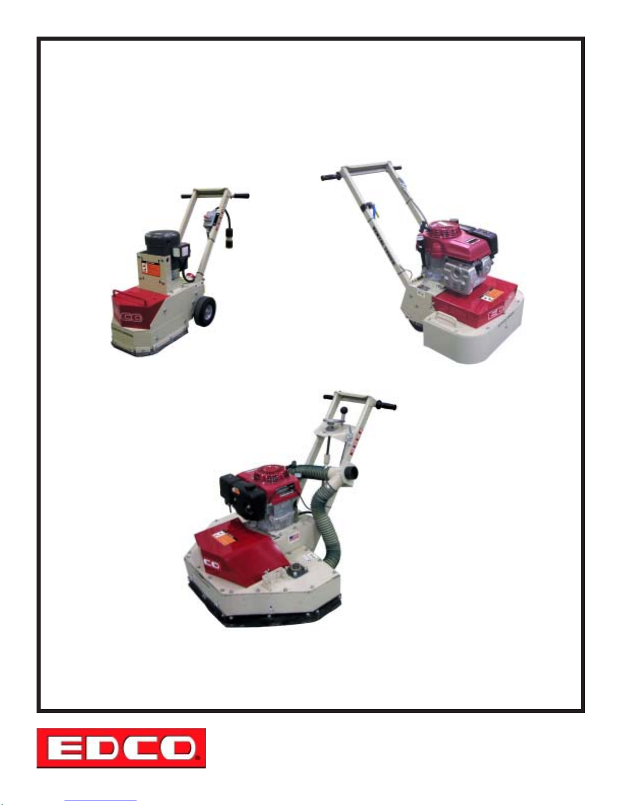
SINGLE DISC MODEL
S-EC
FOUR DISC MODEL
411-E, 411-G, 411GP
DUAL DISC MODEL
2-EC, 2-GC, 2GC-P
Manual - Portable
100 Thomas Johnson Drive, Frederick, MD 21702-4600 USA
Phone (301) 663-1600 • 1-800-638-3326
Fax (301) 663-1607 • 1-800-447-3326
Website: www.edcoinc.com • Email: [email protected]
Printed in USA
TVW ©2003
Page 1
Page 2
E-2EC-2GC-41 1-I-1003
READ AND UNDERSTAND THE OPERATORS INSTRUCTION MANUAL THOROUGHLY
BEFORE ATTEMPTING TO OPERATE THIS EQUIPMENT.
Death or serious injury could occur if this machine is used improperly.
SAFETY
MESSAGES
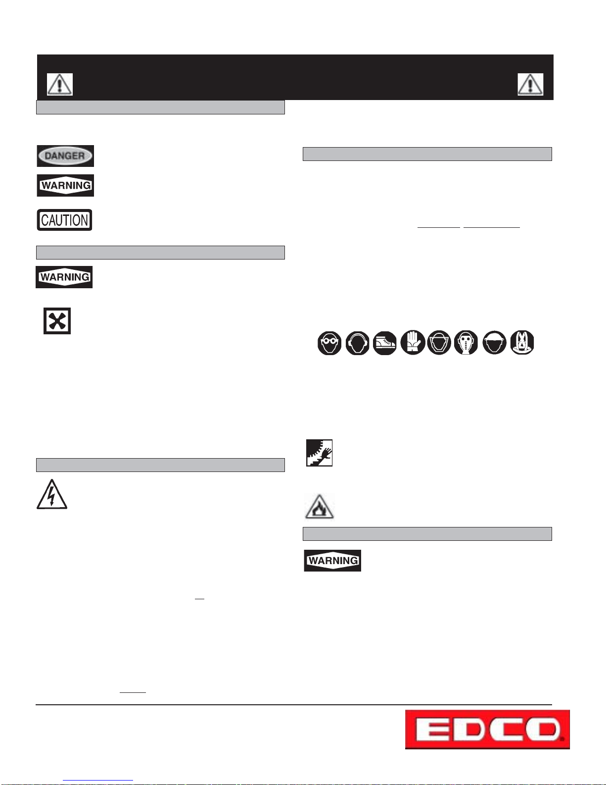
• Safety Instructions are proceeded by a graphic alert symbol of
DANGER, WARNING , or CAUTION.
SAFETY MESSAGES
Indicates an imminent hazard which, if not
avoided, will result in death or serious injury.
Indicates an imminent hazard which, if not
avoided, can result in death or serious injury.
Indicates hazards which, if not avoided, could
result in serious injury and or damage to the
equipment.
GASOLINE/PROPANE POWERED EQUIPMENT
• Engine exhaust from this product contains
chemicals known to the State of California to
cause cancer, birth defects or other reproductive
harm.
• Gasoline is extremely flammable and poisonous.
It should only be dispensed in well ventilated areas,
and with a cool engine.
• Small gasoline engines produce high concentrations of car bon monoxide (CO) example: a 5 HP 4 cycle engine operation
in an enclosed 100,000 cu. ft. area with only one change of air
per hour is capable of providing deadly concentrations of CO
in less than fifteen minutes. Five changes of air in the same
area will produce noxious fumes in less than 30 minutes.
Gasoline or propane powered equipment should not be used
in enclosed or partially enclosed areas. Symptoms of CO poi soning include, headache, nausea, weakness, dizziness,
visual problems and loss of consciousness. If symptoms oc cur - get into fresh air and seek medical attention immediately.
ELECTRICAL POWERED EQUIPMENT
Extreme care must be taken when operating electric
models with water present: Ensure power cord is properly grounded, is attached to a Ground-Fault-Interrupter
(GFI) outlet, and is undamaged.
• Check all electrical cables - be sure connections are tight and
cable is continuous and in good condition. Be sure cable is
correctly rated for both the operating current and voltage of this
equipment.
• Improper connection of the equipment-grounding conductor
can result in a risk of electric shock. Check with qualified electri-
cian or service person if there is any doubt as to whether the
outlet is properly grounded. Adhere to
nances.
• NOTE: In the event of a malfunction or breakdown, grounding
provides a path of least resistance for the electric current to
dissipate. The motor is equipped with a grounded plug and
must be connected to an outlet that is properly installed and
properly grounded. DO NOT modify the plug provided on the
motor. If the plug does not fit the outlet have a qualified electrician install the proper receptacle.
• Switch motor OFF
before disconnecting power.
all local codes and ordi-
• Do not disconnect power by pulling cord. To disconnect, grasp
the plug, not the cord.
• Unplug power cord at the machine when not in use and before
servicing.
GENERAL INSTRUCTIONS
• Equipment should only be operated by trained personnel in
good physical condition and mental health (not fatigued). The
operator and maintenance personnel must be physically able
to handle the bulk weight and power of this equipment.
• This is a one person tool. Maintain a safe operating distance to
other personnel. It is the
other people (workers, pedestrians, bystanders, etc.) away
during operation. Block off the work area in all directions with
roping, safety netting, etc. for a safe distance. Failure to do so
may result in others being injured by flying debris or exposing
them to harmful dust and noise.
• This equipment is intended for commercial use only.
• For the operator’s safety and the safety of others, always keep
all guards in place during operation.
• Never let equipment run unattended.
• Personal Protection Equipment and proper safety attire must
be worn when operating this machinery. The operator must
wear approved safety equipment appropriate for the job such
as hard hat and safety shoes when conditions require. Hearing protection MUST be used (operational noise levels of this
equipment may exceed 90db). Eye protection MUST be worn at
all times.
Keep body parts and loose clothing away from moving
parts. Failure to do so could result in dismemberment
or death.
• Do not modify the machine.
• Stop motor/engine when adjusting or servicing this equipment.
Maintain a safe operating distance from flammable
materials. Sparks from the cutting-action of this machine can ignite flammable materials or vapors.
operators’ responsibility to keep
DUST WARNING
Some dust created by power sanding, sawing,
grinding, drilling, and other construction activities contains chemicals known to cause cancer, birth defects, or other reproductive harm.
Some examples of these chemicals are:
• Lead from lead-based paints, and
• Crystalline silica from bricks and concrete and other
masonry products.
Your risk of exposure to these chemicals varies depending
on how often you do this type of work. To reduce your risk:
work in a well ventilated area, use a dust control system,
such as an industrial-style vacuum, and wear approved personal safety equipment, such as a dust/particle respirator
designed to filter out microscopic particles.
Printed in USA
TVW
©2003
Page 2
100 Thomas Johnson Drive, Frederick, MD 21702-4600 USA
Phone (301) 663-1600 • 1-800-638-3326
Fax (301) 663-1607 • 1-800-447-3326
Website: www.edcoinc.com • Email: [email protected]
Page 3
SPECIFICATIONS
E-2EC-2GC-41 1-I-1003
Section Page Number
Safety/Warnings.....................................................................................................2
Specifications/Table of Contents...............................................................................3
Operating Controls....................................................................................................4
Operating Instructions...........................................................................................6-7
Procedure for adjusting or replacing drive belts...........................................................8
Procedure for installing and removing accessories........................................................9
Instructions for changing accessories.......................................................................10
Three types of accessories........................................................................................11
Silabide pad information..........................................................................................11
Grinder/Surfacer accessories..................................................................................12
Lubricating flange bearings......................................................................................13
Attaching a vacuum...............................................................................................13
Maintenance Instructions........................................................................................14
Maintenance Schedule...........................................................................................15
Limited Equipment Warranty ...........................................................................Back Page
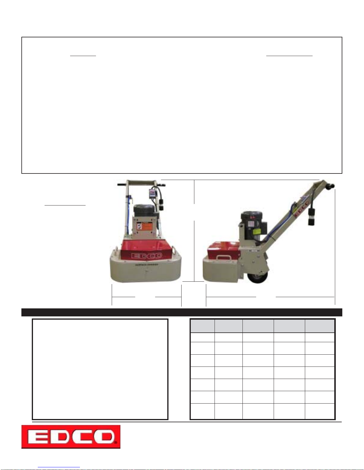
Note:
All dimensions and
weights are for
reference only
and subject to change at
any time.
Table of Contents
B
2-EC Shown
HOW TO ORDER REPAIR PARTS
To insure product safety and reliability, always use genuine
EDCO replacement parts when making repairs to the equipment.
When ordering parts, please specify the MODEL and SERIAL NUMBER of the machine as given on the NAMEPLATE.
In addition, give part number, description and quantity as
listed on the parts list.
Please note: Due to improvements and changes in the equipment the illustrations shown may be different from the actual
machine.
Toll Free: Phone 1-800-638-3326 • Fax 1-800-447-3326
A
Figure 1
S-EC
“A”
“B”
“C”
--
--
Weight
--
100 Thomas Johnson Drive, Frederick, MD 21702-4600 USA
Website: www.edcoinc.com • Email: [email protected]
21 1/4”
37”
42”
--
--
174 lbs.
--
Phone (301) 663-1600 • 1-800-638-3326
Fax (301) 663-1607 • 1-800-447-3326
C
2-EC
24 1/2”
43”
44”
--
--
227 lbs.
--
2- GC
24 1/2”
43”
44”
--
--
240 lbs.
--
411
40”
41”
48”
--
--
435 lbs.
--
Printed in USA
TVW ©2003
Page 3
Page 4
E-2EC-2GC-41 1-I-1003
Operating Controls
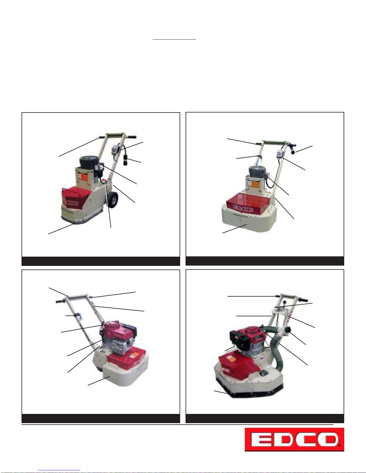
Please Note:
Controls shown are for the model indicated.
The location of these controls may vary on the
different models.
Due to improvements and changes in the
equipment, the illustration shown may be vary
from the actual machine.
Vibration
Dampening
Handles
Dust Skirt
Engine Stop Switch
Water Hook-up
and on/off valve
Recoil
Starter Grip
Choke Control
V acuum port
Electric Powered
(S-EC)
V acuum port
Figure 2
Gasoline Powered
(2-GC)
Power
On/Off
Switch
Electrical
Plug
Electric Motor
Water Hook-up
and on/off valve
back of machine
Cushioned
hand grips
Throttle
Vibration
Dampening
Handles
Water Hook-up
and on/off valve
Dust Skirt
Vibration
Dampening
Handles
Water Hook-up
and on/off valve
Choke Control
Electric Powered
(2-EC)
Electrical
Plug
Power
On/Off
Switch
Electric Motor
V acuum port
Figure 3
Gasoline Powered
(411)
Depth
Control
Throttle
V acuum port
Recoil
Starter Grip
Dust Skirt
NOTE: Operating controls are the same for the gasoline
and propane models.
Figure 4
Printed in USA
TVW
©2003
Page 4
100 Thomas Johnson Drive, Frederick, MD 21702-4600 USA
Phone (301) 663-1600 • 1-800-638-3326
Fax (301) 663-1607 • 1-800-447-3326
Website: www.edcoinc.com • Email: [email protected]
Dust Skirt
NOTE: Operating controls are the same for the gasoline
and propane models.
Figure 5
Page 5
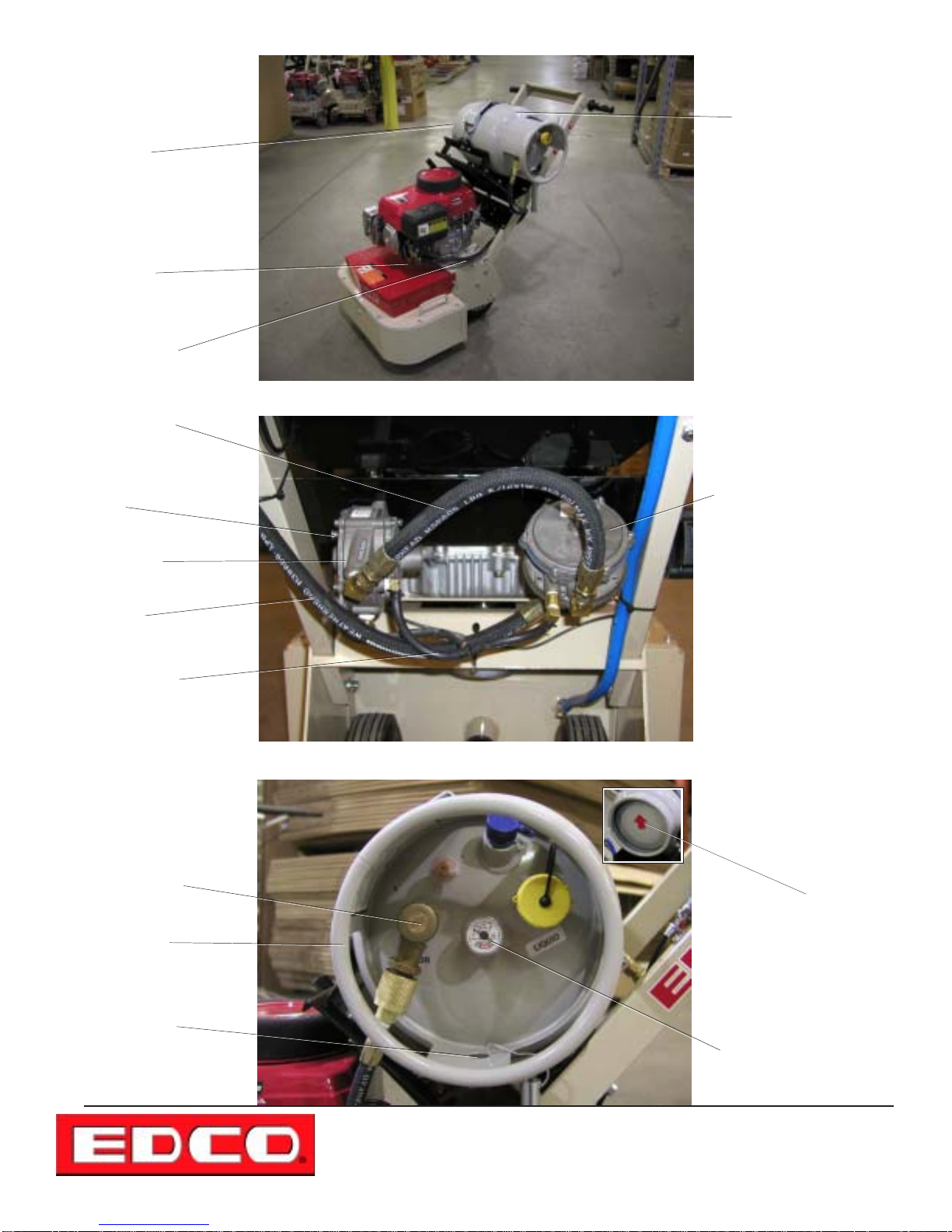
Propane
E-2EC-2GC-41 1-I-1003
System
Red Arrow
Pointing “Up”
T ank Bottom
#1 Main Power
Adjustment
V apor Hose
(Low Pressure)
High Pressure
LP Hose
#2 Idle Mixture
Screw
Dry-Gas
Regulator
Propane T ank
(20 lb horizontal)
V acuum
Fuelock - Filter
High Pressure
LP Hose
V acuum
Hose
Main Fuel
V alve
Propane T ank
(20 lb horizontal)
Locating
Hole
Propane T ank (P/N 15130)
Horizontal Mount (Vapor
Withdrawal)
NOTE: The Red arrow on
the tank will be pointing
“up”. The locating hole is
oriented under the gauge
as viewed in the photo
on the left.
Fuel Gauge
100 Thomas Johnson Drive, Frederick, MD 21702-4600 USA
Phone (301) 663-1600 • 1-800-638-3326
Fax (301) 663-1607 • 1-800-447-3326
Website: www.edcoinc.com • Email: [email protected]
Printed in USA
TVW ©2003
Page 5
Page 6
E-2EC-2GC-41 1-I-1003
Operating Instructions
• Read and understand all operating instructions before operating this equipment. Death
or serious injury can result if this machine is used improperly .
• Concrete grinders are designed to be used to grind flat horizontal concrete slabs using EDCO approved
accessories.
• The machines are equipped with gasoline/propane engines and electric motors.
• They are designed to be controlled by a single operator from a position at the rear of the machine.
• When operating equipment maintain a safe distance from other personnel in the area.
Be sure to read the complete instructions supplied with your machine.
IMPORTANT: Perform Pre-S tart Check.
• Visually inspect the equipment for wear or damage.
• Be sure all guards are in place and functioning properly . Do not operate unless all guards are in place and secure.
• Perform all daily maintenance.
• Check to be sure water tubes are functioning properly if performing wet-grinding operations.
• Inspect accessories - Be sure the correct accessory is installed properly on the machine, mounting arrangement and its
intended use.
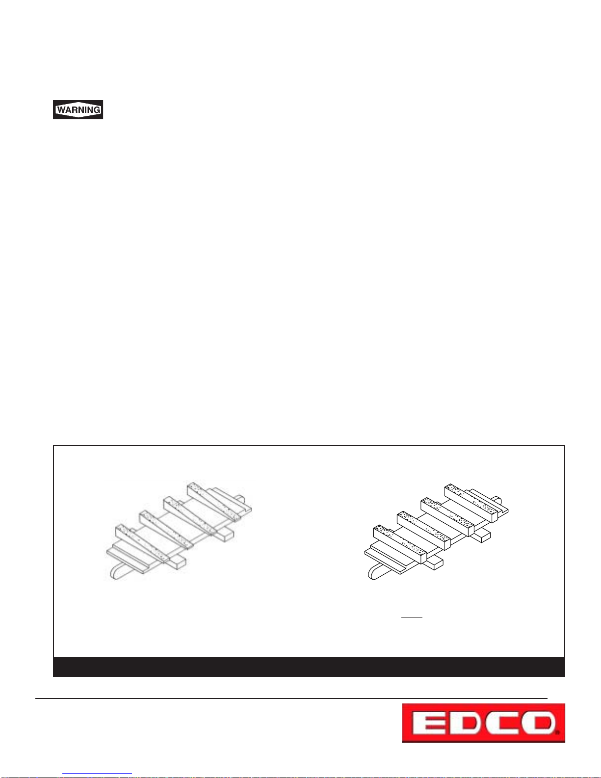
• Check accessories for damage (see figure 6, below), the type of wear or damage will vary with the type if accessory .
• Inspect work area to determine the presence and location of deck inserts, pipes, columns and objects protruding from
the slab surface so that they may be avoided during the grinding operation.
• FOR WET GRINDING: Attach the water supply . A flow rate of approximately 1/2 gallon per minute is recommended.
EXAMPLE OF SEVERELY WORN
DYMA-SERT
The above in an example of a DYMA-SERT that has not
been rotated after every four hours of use. To get maximum life out of a DYMA-SERT they should be rotated
180º every four hours of use.
Printed in USA
TVW
©2003
Page 6
100 Thomas Johnson Drive, Frederick, MD 21702-4600 USA
Phone (301) 663-1600 • 1-800-638-3326
Fax (301) 663-1607 • 1-800-447-3326
Website: www.edcoinc.com • Email: [email protected]
EXAMPLE OF AN EVENLY WORN
DYMA-SERT
The above in an example of a DYMA-SERT that has
been rotated after every four hours of use, as you can
see the wear is even across all segments.
Figure 6
Page 7

E-2EC-2GC-41 1-I-1003
Operating Instructions
• BEFORE STARTING THE ENGINE: Raise the front of the machine clear of the working surface.
• START ENGINE AND ALLOW IT TO REACH OPERATING SPEED. Position the grinder at the starting point.
Bring the engine to full speed. Lower the machine onto the slab surface. Use a slow sweeping motion from left right
and back continously , and do not force the machine into the work, the engine or motor should not strain
when grinding.
• WHEN WET GRINDING: Water is required. Attach the water hose to the water hook-up valve. Use the valve to
control the flow of water.
• FOR DRY GRINDING: Provide a respirator and dust control system.
• FOR GASOLINE MODELS: Put the engine stop switch in the “RUN” position. Consult the engine manufac-
turers operating instructions and follow the directions for starting and breaking in the engine.
• TO STOP THE MACHINE: S top forward motion. On gasoline models push the throttle to idle. T urn ignition
or power switch off and let the engine come to a complete stop. T urn of f the water supply.
• WHEN MANEUVERING THE GRINDER: Tilt grinder back enough so it does not strike the slab surface. Damage to
accessories may occur with inadvertent contact with the slab.
• DO NOT FORCE GRINDER WHILE GRINDING .
• IF THE POWER SOURCE FAILS: Raise the grinder of f of the floor. Disconnect the power source (i.e. the
spark plug wire on a gasoline engine). Inspect the accessories for damage. Replace damaged (or questionable)
accessories immediately.
• WHEN TRANSPORTING THE GRINDER: Disconnect the power source before lifting or removing any guard.
See the directions for changing accessories on page 9.
• WHEN HOISTING OR LIFTING A GRINDER : Always inspect frame and attaching hardware for damage
before lifting. Use proper safe hoisting and lifting techniques and hardware.
100 Thomas Johnson Drive, Frederick, MD 21702-4600 USA
Phone (301) 663-1600 • 1-800-638-3326
Fax (301) 663-1607 • 1-800-447-3326
Website: www.edcoinc.com • Email: [email protected]
Printed in USA
TVW ©2003
Page 7
Page 8
E-2EC-2GC-41 1-I-1003
PROCEDURE FOR ADJUSTING OR REPLACING DRIVE BELT
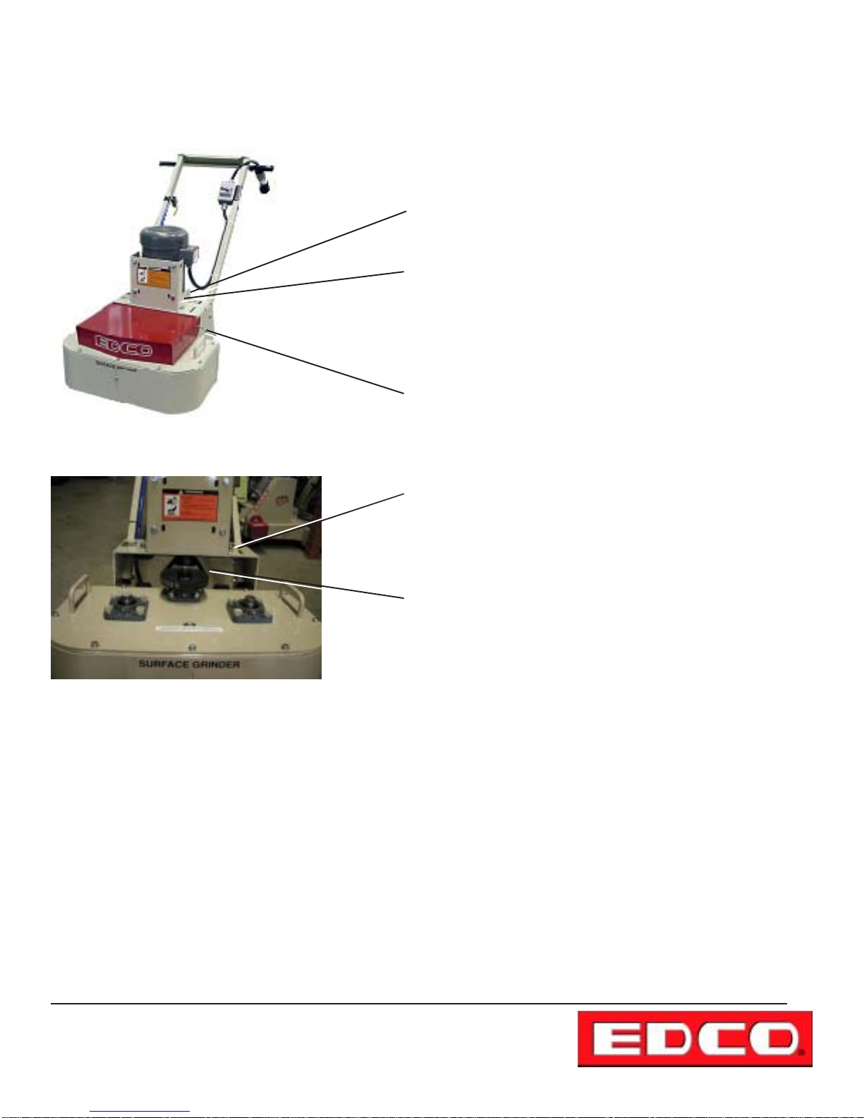
NOTE: The following applies to all machines. They all adjust in
the same manner .
T o adjust the drive belt loosen four (4) cap screws securing the
motor mount to the frame.
Slide the motor mount to the rear of the machine to increase belt
tension.
Tighten the four (4) cap screws loosened earlier maintaining
pressure on the motor mount to prevent loosening.
T o replace the belt, remove the (red) hood by removing two (2) cap
screws, one on each side of the machine.
Loosen the four (4) cap screws as in the first step and slide the
motor mount all the way forward.
Remove the belt from the motor and pinion shaft sheaves as
shown in the photo on the left.
Reverse the previous step to install new belt. Slide motor mount
towards the rear of the machine and adjust belt tension, tighten all
four (4) cap screws as explained above. Replace red hood and
tighten bolts.
New belts should be retensioned after grinder has been used for 4
hours.
Printed in USA
TVW
©2003
Page 8
100 Thomas Johnson Drive, Frederick, MD 21702-4600 USA
Phone (301) 663-1600 • 1-800-638-3326
Fax (301) 663-1607 • 1-800-447-3326
Website: www.edcoinc.com • Email: [email protected]
Page 9
E-2EC-2GC-41 1-I-1003
PROCEDURE FOR INSTALLING AND REMOVING ACCESSORIES
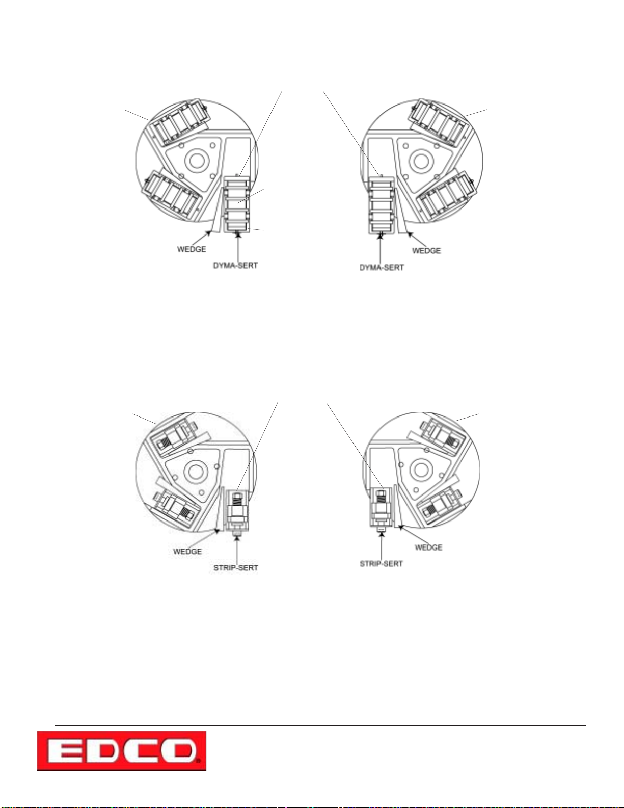
Place wooden block against this surface and tap with
hammer or mallet to remove accessory
MUL TI-DISC
""
"
""
LH Multi-disc
T o inst all an accessory , there are several different types but all inst all in the same manner , use a brass rod or similar malable
material to drive the wooden wedge into place as shown in the above and below illustrations, note on which side of the
accessory the wooden wedge is positioned (near center of disc). Never mix worn or used accessories with new ones. It will
cause vibration and an uneven work surface. Replace accessories in complete sets, never mix sets.
Place wooden block against this surface of the Strip-Sert
and tap with hammer or mallet to remove.
This is the part of
the Dyma-Sert that
is rotated 180°
Not the DYMASERT case.
RH Multi-disc
MUL TI-DISC
!!
!
!!
MUL TI-DISC
""
"
""
LH Multi-disc
T o remove an accessory , there are several different types, all are removed in the same manner , use a wooden block as
explained in the above illustration. Never hammer directly on any accessory , damage to the self adjusting system will result
and the accessory will have to be replaced.
NOTE: THE ABOVE ILLUSTRATIONS ARE VIEWING THE MACHINE FROM THE
FRONT BOTTOM. NOTE THE DIRECTION OF ROTATION AND MULTI-DISC
STYLE. IF DISCS ARE REPLACED AND INSERTS FALL OUT WHEN BEING
USED THE DISCS HAVE BEEN INSTALLED INCORRECTLY.
MUL TI-DISC
!!
!
!!
RH Multi-disc
100 Thomas Johnson Drive, Frederick, MD 21702-4600 USA
Phone (301) 663-1600 • 1-800-638-3326
Fax (301) 663-1607 • 1-800-447-3326
Website: www.edcoinc.com • Email: [email protected]
Printed in USA
TVW ©2003
Page 9
Page 10
E-2EC-2GC-41 1-I-1003
1.
INSTRUCTIONS FOR CHANGING ACCESSORIES
Disconnect the machine from the power
source before performing any work on the
equipment. T o disconnect the power source remove the sp ark
plug lead on gasoline and propane models or unplug the electrical models at the grinder.
2. Tip Grinder back on the handle until handle remains on
contact with the slab. NOTE: FOR GASOLINE MODELS,
T AKE CARE THA T GASOLINE OR OIL DOES NOT SPILL
FROM THE ENGINE, T urn gasoline cutoff valve off. Brace
securely or have someone hold the handle against the slab.
The grinding discs will be visible and accessable for inspection and installation of accessory items.
3. Installing Multi-disc assemblies (for use with scarafiers,
silabide pads, wire brushes and Dyma-Serts). The multi-discs
are designed as lefthand (LH) or righthand (RH) depending on
the direction of rotation: the LH is on the left side (clockwise)
and RH is on the right side (counter clockwise) as viewed from
the bottom side of the machine. The single disc grinders use
the RH disc. NOTE: Multi-Discs come standard with the EDCO
grinders in this manual. The multi-disc assemblies use a 3/8”
dia. x 2” long roll pin to attach them to the shaft(s) under the
grinder (refer to page 1 1).
The scarifiers can be added or removed from the case without
disturbing the case. One end of the scarifier is short and has
a tab. The tab is simply inserted under the lip of the case and
the other end is pressed into the spring loaded slot and seated
firmly . Refer to diagram on page 1 1.
T o remove the scarifier from the case, simply pry the rounded
end of the frame out of the spring loaded slot.
Installing Dyma-Serts: The Dyma-Sert assembly consists
of a disposable Dyma-Sert cutter, a shock absorbing rubber
block, and a reusable Dyma-Sert case. Three Dyma-Sert assemblies are used on each multi-disc. The case is held on the
multi-disc assembly by using a hardwood wedges driven in on
the inside of the case. Refer to diagram on page 1 1.
The Dyma-Serts can be added added or removed from the
reusable case. One end of the Dyma-Sert has a lip. The lip is
simply inserted under the lip of the case and the other end is
pressed into the spring loaded slot at the other end and seated
firmly . Refer to page 1 1.
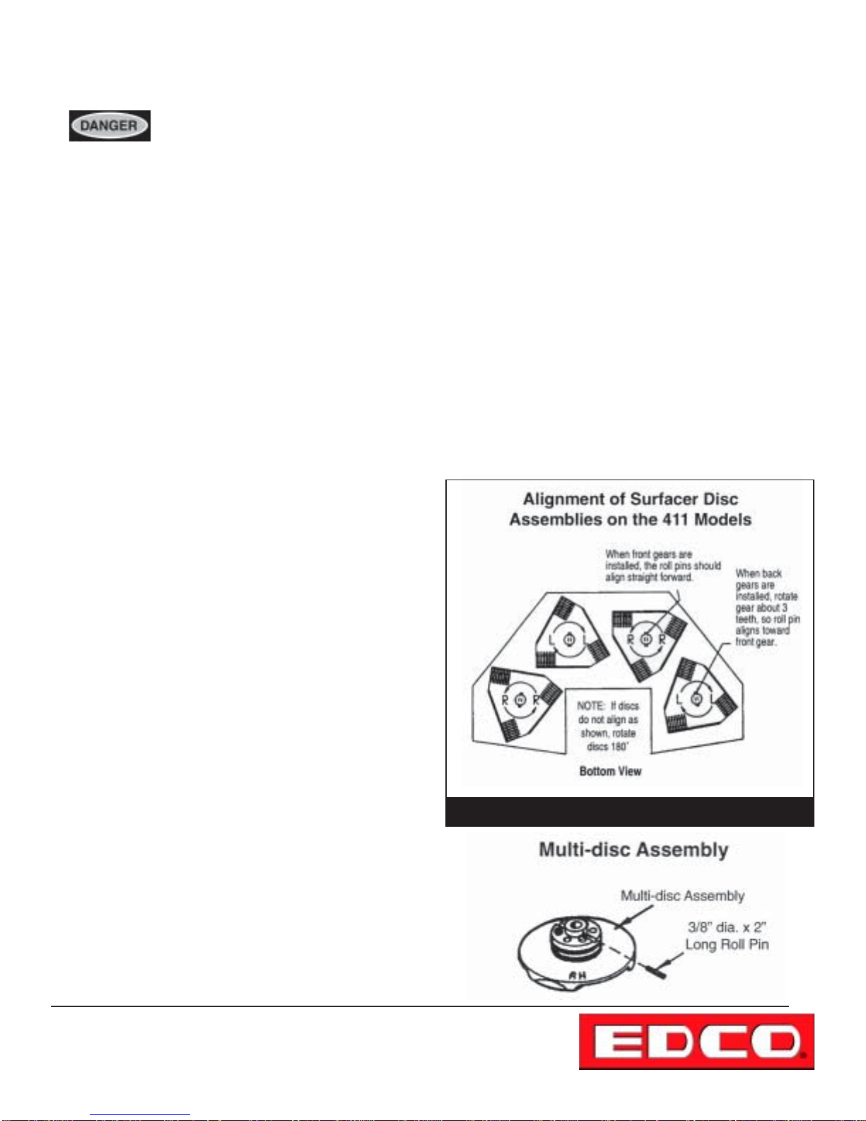
4. When installing the surfacer disc assemblies instead of
the Multi-disc assemblies (refer to figure 7). The discs are
triangular and must be allowed to pass each other without
colliding.
5. Installing grinding stones. Grinding stones are used on the
multi-disc assembly. A total of 3 stones are used with each
multi-disc and are held in place with a hardwood wedge. The
wedges are placed on the inside of the stone (refer to page
10). Use a second wedge and hammer or mallet to drive the
wedge securely ito place.
6. Installing wire brushes. The steel wire brushes are used
on the multi-disc assembly (3 per multi-disc). They are held
in place with a hardwood wedge driven in on the inside of the
brush toward the center of the disc, refer to the previous page.
All accessories are held in place in the same manner.
7. Installing Scarifiers. The scarifier assemblies consist of
disposable scarifiers and a reusable scarifier case. The case
is held into the multi-disc assembly with a hardwood wedge
driven in on the inside of the case toward the center of the
disc, refer to the previous page. All insert s are held in place in
the same manner.
Figure 7
Printed in USA
TVW
©2003
Page 10
100 Thomas Johnson Drive, Frederick, MD 21702-4600 USA
Phone (301) 663-1600 • 1-800-638-3326
Fax (301) 663-1607 • 1-800-447-3326
Website: www.edcoinc.com • Email: [email protected]
Page 11
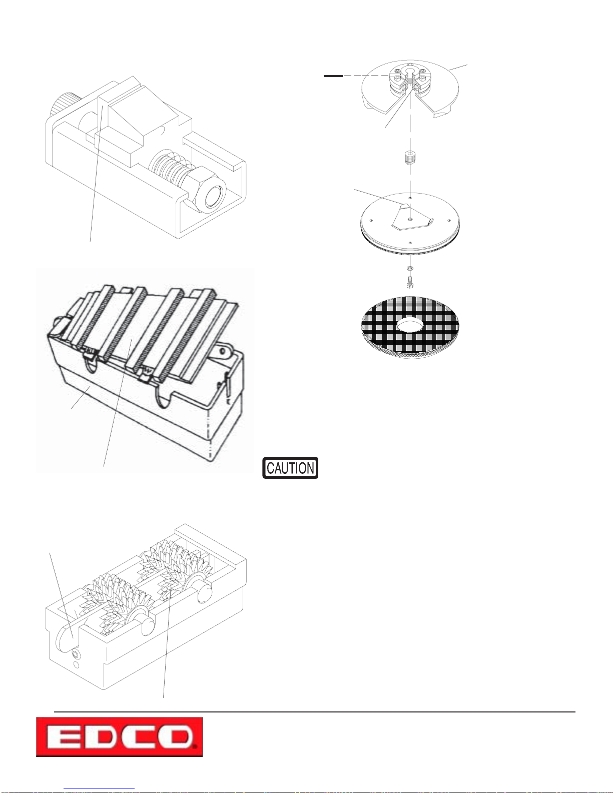
THREE TYPES OF
ACCESSORIES
This is a STRIP-SERT, rotate this blade to expose a new cutting surface. There are four (4) cutting surfaces on each blade.
SILABIDE PAD INSTALLATION
Roll Pin
Threaded
Hub
Hub Stud
Non Spin T ab (3)
Flat Washer
Cap Screw
E-2EC-2GC-41 1-I-1003
MUL TI-DISC
Pad Driver Disc
Accessory
case
This is a DYMA-SERT, rotate the DYMA-SERT
only , not the case.
Spring loaded slot
Silabide Pad
Exploded view of Silabide Pad assembly .
Installing Silabide Pads:
threaded hub, this is a permanent installation and the stud need not be
removed when using the surfacer as a grinder or scarafier.
Be sure that the end of the stud, when fully threaded
into hub, does not project past web of multi-disc assembly . Y our surfacer is now ready to receive the P AD
DRIVER DISC anytime the need arises.
Install Hub Stud - one in each
To install Pad Driver Disc: Position P AD DRIVER DISC
against the web of the multi-disc, be sure “non-spin-tabs” are in place
(see illustration) in the center casting web to prevent disc from turning
loose. Be sure Pad Driver Disc is positioned flat against the casting.
Insert capscrew with flat washer through hole in Pad Driver Disc and
thread into Hub Stud. Tighten securly. Follow these instructions for
each disc assembly (refer to figure above).
This is a Scarifier and does not require rotation.
Install Silabide Pads by pushing the pad against the bristles. The pad
should stay on the disc and the surfacer can then be lowered to it’s
normal position.
When using the surfacer as a scrubber, try not to lif t the surfacer from
the slab except to remove or change pads. If the pad comes loose
from the disc, stop the surfacer and repeat Pad installation from step
#1 (disconnect the power source).
100 Thomas Johnson Drive, Frederick, MD 21702-4600 USA
Phone (301) 663-1600 • 1-800-638-3326
Fax (301) 663-1607 • 1-800-447-3326
Website: www.edcoinc.com • Email: [email protected]
Printed in USA
TVW ©2003
Page 11
Page 12

E-2EC-2GC-41 1-I-1003
GRINDER/SURF ACER ACCESSORIES
(for the models listed in this manual)
Dyma-Serts (Patented)
DYMA-SERTS are diamond segments welded to snap-in
plates for faster, controlled, dry grinding, and are ideal for
removing trowel marks, rough finish, rain spots, large volume
projects, paints, thin mastics, epoxy and urethane coatings,
or polymer enhanced surfaces. DYMA-SERTS can be used
wet or dry and will outperform stones by grinding many times
faster, removing tough materials, and lasting many times
longer - up to 30,000 sq. ft. (2,800 sq. meters) life (at 1/32”)
dependent on depth of removal, coatings, speed of operation,
matrix, etc. Extra weight can be added to the grinder to
increase production. Choose the DYMA-SERT to fit your job.
EG-1X General purpose matrix for fast grinding of
concrete, thin mastics, paints or urethane and epoxy thin
coats.
EG-2X Use on abrasive material. Matrix is designed
harder for concrete less than 72 hours old, brick or abrasive
sands. Grinding will be slower and tool life will be longer.
EG-3X Hardest matrix for use on rough surfaces such
as epoxy mortars or sharp aggregates (flint, granite, etc.).
NOTE: Dyma-Serts for use on terrazzo are available - call
EDCO for additional information.
Grinding Stones
Grinding Stones are generally used when there is a need to
remove trowel marks, rain spots, excess concrete, rough
finishes, or high spots less than 1/16” (2mm) in height. A
variety of grit sizes are available, beginning with a super
course C-10-S to very fine polishing types C-80 and C-120
used to grind terrazzo and marble. The EDCO grinder will
remove up to 1/16” (2mm) of concrete at the rate of approximately 500 sq. ft/hr . (46 sq. m/hr .) using grinding stones of
the C-10-S grit. Extra weight can be added to the grinder to
improve the grinding speed. The hardness of the surface,
size of aggregate, age of slab or additives and sealers
required to meet surface specifications will affect the grinding
speed and rate of removal.
Industrial Surfacer Discs
Industrial Surfacer Discs with replaceable hi-carbon steel
cutters can be used in place of the multi-accessory discs to
create a simple, high speed cleaning system and save hours
of hard work, intensive labor when hardened deposits of
material such as fiberglass, ice, sugar, rubber , etc., have to
be removed from factory floors.
Cutter wheels are easily changed and may be space to fit
your particular job. Ideal for use in foundries, sugar refineries,
walk-in freezers, mobile home and recreational vehicle
manufacturers, rubber tire/hose/belt plants, paint booths,
boat/tub/shower manufacturers, steel mills or fabricating
plants.
Silabide Pads
Silabide Pads are special nylon mesh pads impregnated with
silicon carbide grit designed for super scrubbing action. Use
to remove fins or marks on gyp-crete or other underlayment
materials. Remove mildew, rust or discolorations from
concrete, clean concrete forms and strip scale and rust from
slab steel plate surfaces. Silabide pads can be used with
detergents or dry and are attached to the EDCO Grinder with
a pad driver assembly .
Scarifiers (used with “multi-discs”)
Scarifiers are used to grind slab surfaces. The action is
faster than with grinding stones leaving a “rough sandpaper
finish” that may be desirable for non-slip floors, ceramic tile
installation or epoxy mortars.
The action of the steel cutter wheels is to “pick” away the
concrete from around the aggregates. The cutter will not
grind the aggregate, consequently , the aggregate will remain
exposed and above the surface of the slab. In some instances the aggregate will loosen or split and break away
from the concrete bond. This condition can be controlled and
is useful when an exposed aggregate surface is required.
If the desired end result is a smooth, flat surface - use
scarifiers first for fast surface removal, then change to coarse
grit (C-10-S) grinding stones to bring the high aggregate to
the level of the slab.
EDCO offers two (2) models of scarifiers. The standard small
cutter wheel assembly has sharp carbon steel cutters
suitable for all scarifying applications. Life of this assembly
is from 3 to 6 hours depending on the surface material. The
heavy duty cutter assembly has an anticipated life from 8 to
20 hours. Action is basically the same as the st andard units
except cutting life is extended. Use it where changing cutter
assemblies often is not convenient.
Printed in USA
TVW
©2003
Page 12
100 Thomas Johnson Drive, Frederick, MD 21702-4600 USA
Phone (301) 663-1600 • 1-800-638-3326
Fax (301) 663-1607 • 1-800-447-3326
Website: www.edcoinc.com • Email: [email protected]
Page 13
E-2EC-2GC-41 1-I-1003
PROCEDURE FOR LUBRICATING FLANGE BEARINGS
Inspection
hole
Gear
case
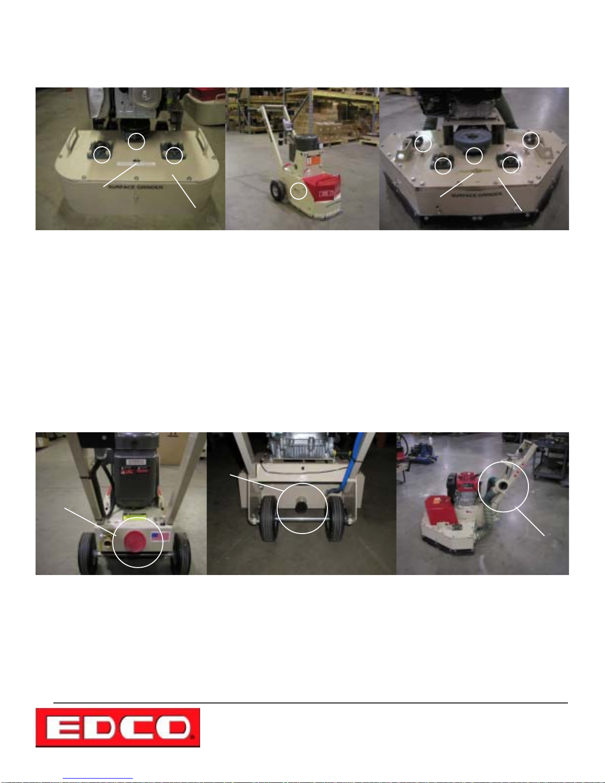
The procedure is the same for two or four disc machines. The red hood has to be removed to access the grease points on
theflange bearings. The single disc grinder is lubricated from the fittings on the exterior of the machine. The grease points are
circled in the photos above. There are duplicate grease fittings on the underside of the 2-EC, 2-GC and the 41 1 models. The
skirts will have to be removed to access the grease points.
T o grease the flange bearings att ach the grease gun to the grease fittings and give only two (2) pumps on the grease gun
every 50 hours of use. If excessive over lubrication is done grease will leak onto the work surface causing possible damage
and wasted cleanup time.
Inspection
hole
Gear
case
PROCEDURE FOR ATTACHING A VACUUM
Vac
Port
Vac
Port
Vac
Port
S-EC
2-GC
If using a vacuum for dust control attach it to the vacuum port at the rear of the machine except for the 41 1 which is on the
handle as pictured above, securing it with clamps. The ports are circled in the photos above.
41 1
100 Thomas Johnson Drive, Frederick, MD 21702-4600 USA
Phone (301) 663-1600 • 1-800-638-3326
Fax (301) 663-1607 • 1-800-447-3326
Website: www.edcoinc.com • Email: [email protected]
Printed in USA
TVW ©2003
Page 13
Page 14

E-2EC-2GC-41 1-I-1003
MAINTENANCE INSTRUCTIONS
1. Disconnect the machine from the power source. Remove the spark plug lead on the propane and gasoline
engine models or disconnect the supply voltage connector at the machine on electric models before performing
any maintenance. All maintenance to be performed by qualified personnel.
2. Never work under equipment without first properly securing the equipment to prevent it from moving or falling. Always work on
a flat and level surface.
3. For Propane and Gasoline Models, refer to the engine manual for maintenance information specific to the engine being used.
~Be sure to check oil level before operation (while engine is cold).*
~Clean air filter element daily .
4. Grease bearings after every 50 hours of use. Refer to page 13 for lubrication points.**
5. Perform a visual inspection of the entire machine before each operation. Be sure all fasteners are tight and secure, check for
signs of metal cracking or fatigue, inspect for damage to electrical wiring, damage to fuel lines, check bearings and inspect to
be sure proper guards are in place and secure.
6. Inspect belts before each operation. Check belt tension. On new equipment belts should be re-tensioned after the first few
hours of use. Damaged, stretched or excessively worn belts should be replaced with a new
transfer.
matched set for maximum power
T o tension belts, loosen engine/motor mounting hardware slightly . Adjust the engine/motor position until the belts are tight. Retorque the engine/motor muounting hardware, refer to page 8.
Proper belt tension must be maintained to transmit the engine/motor power to the grinding disc. Slipping belts will overheat, the
disc life will be shortened and the cutting speed limited. Over tensioned belts will shorten the belt and bearing life.
7. Before operation, check Grinding Discs to be sure they are tight. Grinding discs loosen with use. Tighten bolts (4 on each
disc) as required.
8. Before operation, check Neoprene bushing for wear and replace as necessary .
9. On gasoline and propane models inspect spark plugs. Clean if dirty , replace if the electrodes are burned. Gap plugs at .020”.
* For Propane Models use a mild detergent motor oil that will not leave ash deposits. “Gas engine oils” are available from major
petroleum companies. These “gas engine oils” are specifically blended for long-life on LP-Gas or natural gas engine operation,
which will not carbon up the combustion chamber or shorten valve life. Premium oils should not be used in LP-Gas or natural gas
engines as the metallic detergents will damage the engine valves.
** Gear Case “A” (refer to figure on page 13 )
The gear case of your EDCO grinder has been pre-lubricated at the factory with approximately 3 pounds of lubriplate, No. 6302 grease. We recommend it’s continued use.
Each grinder has an inspection hole in the gear case top plate to tnable you to check the amount of grease in the case. Remove
this cover with the end of a screwdriver, if grease is visible do not add any . If you cannot see the grease, add a small amount (1
pound is usually more than enough). Do not overfill. The grease in the gear case should last from three to five years before there
is any need to refill or add. (Note: Models SEC/SGC are not gear driven so this does not apply).
Bearings “B” (refer to figure on page 13)
Each grinder has bearings on top and bottom of the machine. All bearings are self-aligning, sealed unit s equipped with grease
fittings. These bearings should be lubricated every 50 hours of operation with Lubriplate No. 630-2, or other good bearing grease.
DO NOT over lubricate.
An occasional drop or two of oil on the wheel bearings will help prevent binding.
Printed in USA
TVW
©2003
Page 14
100 Thomas Johnson Drive, Frederick, MD 21702-4600 USA
Phone (301) 663-1600 • 1-800-638-3326
Fax (301) 663-1607 • 1-800-447-3326
Website: www.edcoinc.com • Email: [email protected]
Page 15
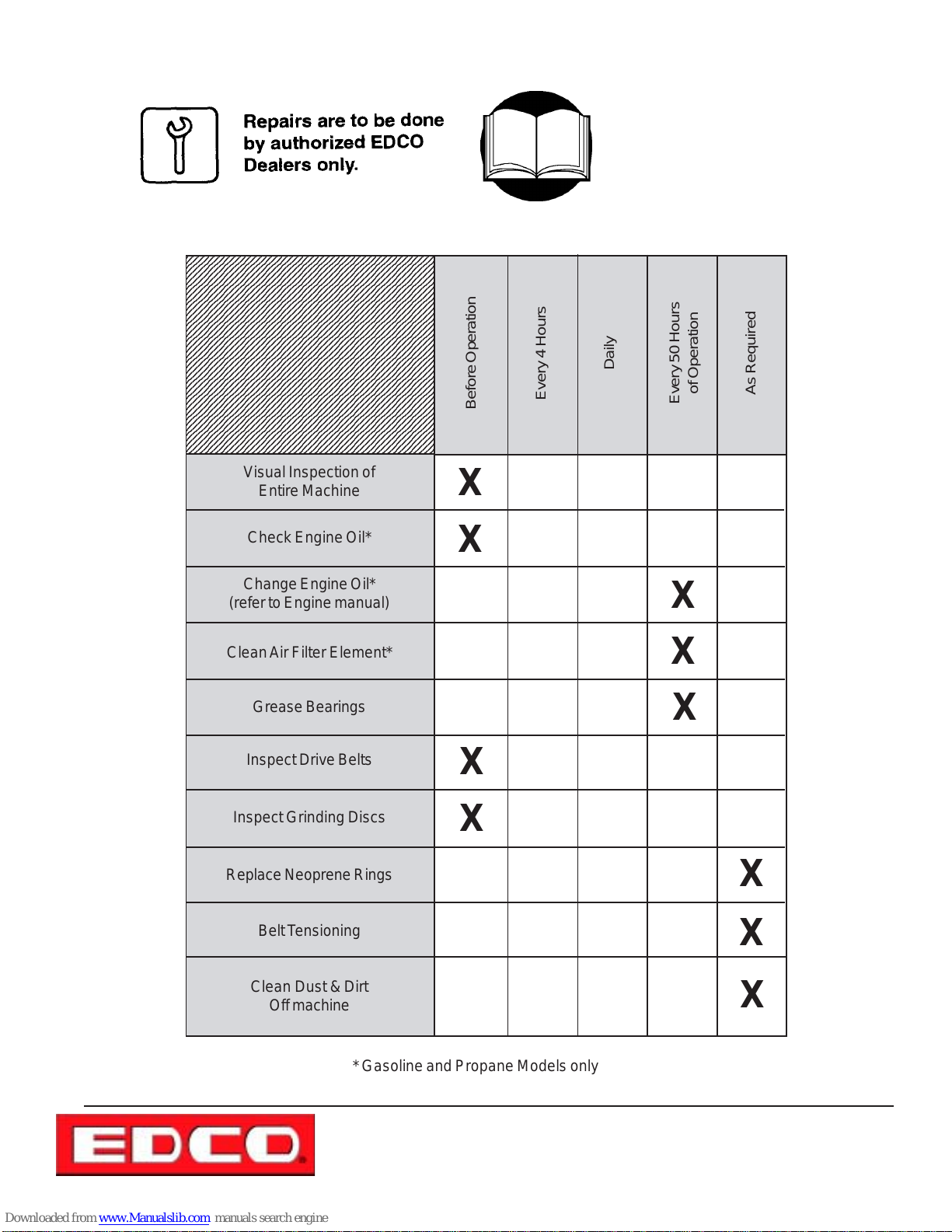
Maintenance Schedule
7
7
7
7
7
7
7
7
7
7
7
7
7
7
7
7
7
7
7
7
7
7
7
7
7
7
7
7
7
7
7
7
7
7
7
7
7
23456789012345678901234567890121234567890123456
23456789012345678901234567890121234567890123456
23456789012345678901234567890121234567890123456
23456789012345678901234567890121234567890123456
23456789012345678901234567890121234567890123456
23456789012345678901234567890121234567890123456
23456789012345678901234567890121234567890123456
23456789012345678901234567890121234567890123456
23456789012345678901234567890121234567890123456
23456789012345678901234567890121234567890123456
23456789012345678901234567890121234567890123456
23456789012345678901234567890121234567890123456
23456789012345678901234567890121234567890123456
23456789012345678901234567890121234567890123456
23456789012345678901234567890121234567890123456
23456789012345678901234567890121234567890123456
23456789012345678901234567890121234567890123456
23456789012345678901234567890121234567890123456
23456789012345678901234567890121234567890123456
23456789012345678901234567890121234567890123456
23456789012345678901234567890121234567890123456
23456789012345678901234567890121234567890123456
23456789012345678901234567890121234567890123456
23456789012345678901234567890121234567890123456
23456789012345678901234567890121234567890123456
23456789012345678901234567890121234567890123456
23456789012345678901234567890121234567890123456
23456789012345678901234567890121234567890123456
23456789012345678901234567890121234567890123456
23456789012345678901234567890121234567890123456
23456789012345678901234567890121234567890123456
23456789012345678901234567890121234567890123456
23456789012345678901234567890121234567890123456
23456789012345678901234567890121234567890123456
23456789012345678901234567890121234567890123456
23456789012345678901234567890121234567890123456
23456789012345678901234567890121234567890123456
Visual Inspection of
Entire Machine
Before Operation
X
Read and follow
instructions in the engine
owners’ manual.
Daily
Every 4 Hours
E-2EC-2GC-41 1-I-1003
of Operation
Every 50 Hours
As Required
Check Engine Oil*
Change Engine Oil*
(refer to Engine manual)
Clean Air Filter Element*
Grease Bearings
Inspect Drive Belts
Inspect Grinding Discs
Replace Neoprene Rings
Belt T ensioning
Clean Dust & Dirt
Off machine
X
X
X
* Gasoline and Propane Models only
100 Thomas Johnson Drive, Frederick, MD 21702-4600 USA
Phone (301) 663-1600 • 1-800-638-3326
Fax (301) 663-1607 • 1-800-447-3326
Website: www.edcoinc.com • Email: [email protected]
X
X
X
X
X
X
Printed in USA
TVW ©2003
Page 15
Page 16

E-2EC-2GC-41 1-I-1003
LIMITED EQUIPMENT WARRANTY
Equipment Development Company, Inc. herein
referred to as EDCO warrants that each new unit
manufactured by EDCO to be free from defects in
material and workmanship in normal use and service
for a period of (1) one year (except in the case of the
cutter drum assembly on all model concrete asphalt
planes, in which case the warranty period shall be 90
days) from date of shipment to the original buyer or
equipment rental center owner.
EDCO will, at its option, repair or replace, at the
EDCO factory or at a point designated by EDCO any
part, which shall appear to the satisfaction of EDCO
inspection to have been defective in material or
workmanship.
This warranty , does not apply to failure occurring as a
result of abuse, misuse, negligent repairs, corrosion,
erosion, normal wear and tear, alterations or
modifications made to the product without express
written consent of EDCO: or failure to follow the
recommended operating practices and maintenance
procedures as provided in the products operating and
maintenance manuals.
This warranty does not obligate EDCO to bear any
transportation charges in connection with the
replacement or repair of defective parts. This
warranty does not obligate EDCO to bear any expense
for travel time or of personnel in connection with any
service calls.
Accessories or equipment furnished and installed on
the product by EDCO but manufactured by others,
including but not limited to engines, motors, electrical
equipment, transmissions, etc., shall carry the
accessory manufacturers’ own warranty.
THIS WARRANTY IS IN LIEU OF ALL OTHER
WARRANTIES, EXPRESSED OR IMPLIED, OR
STATUTORY, INCLUDING ANY WARRANTIES OF
MERCHANTABILITY OR OF FITNESS FOR A
P ARTICULAR PURPOSE.
LIABILITY LIMITATIONS
The remedies of the user set forth under provisions
of warranty outlined above are the exclusive and total
liability of EDCO with the respect to their sale or the
equipment and service furnished hereunder, in
connection with the performance or breach thereof,
or from the sale, delivery, installation, repair or
technical direction covered by or furnished under the
sale, whether based on contract, warranty,
negligence, indemnity , strict liability , or otherwise shall
not exceed the purchase price of the unit of equipment
upon which such liability is based.
EDCO will not in any event be liable to the user, any
successors in interest or any beneficiary or assignee
relating to this sale for any consequential, incidental,
indirect, special or punitive damages arising out of
this sale or any breach thereof, or any defects on, or
failure of, or malfunction of the equipment under this
sale based upon loss of use, lost profits or revenue,
interest, lost goodwill, work stoppage, impairment of
other goods, loss by reason of shutdown or nonoperation, increased expenses of operation of the
equipment, cost of purchase or replacement power
of claims of users or customers of the user for service
interruption whether or not such loss or damage is
based on contract, warranty, negligence, indemnity,
strict liability , or otherwise.
EDCO reserves the right to modify , alter and improve
any part or parts without incurring any obligation to
replace any part or parts previously sold without such
modified, altered or improved part or parts.
No person is authorized to give any other warranty or
to assume any additional obligation on EDCO’s behalf
unless made in writing and signed by an officer of
EDCO.
Equipment Development Company, Inc.
USE ONLY GENUINE EDCO PARTS AND ACCESSORIES
For your own safety, the safety of others and the life of your machine
Printed in USA
TVW
©2003
Page 16
100 Thomas Johnson Drive, Frederick, MD 21702-4600 USA
Phone (301) 663-1600 • 1-800-638-3326
Fax (301) 663-1607 • 1-800-447-3326
Website: www.edcoinc.com • Email: [email protected]
 Loading...