

Edco CPM-4, CPM-8, CPM-10, ScariLite-8 Operator's Instruction Manual

E-CPM-4-8-10-SL8-I-0309
Operator’s Instruction Manual
COMPACT PLANER
Models CPM-4, CPM-8, CPM-10
ScariLite-8
CPM-4
CPM-10
ScariLite-8
Gasoline/Electric/Propane
Concrete/Asphalt Planer
Manual - Portable
CPM-8
100 Thomas Johnson Drive, Frederick, MD 21702-4600 USA
Phone (301) 663-1600 • 1-800-638-3326
Fax (301) 663-1607 • 1-800-447-3326
Website: www.edcoinc.com
Email: sales@edcoinc.com
Printed in USA
TVW ©2009
Page 1
E-CPM-4-8-10-SL8-I-0309
READ AND UNDERSTAND THE OPERATORS INSTRUCTION MANUAL THOROUGHLY
Death or serious injury could occur if this machine is used improperly.
BEFORE ATTEMPTING TO OPERATE THIS EQUIPMENT.
SAFETY
MESSAGES
• Safety Instructions are proceeded by a graphic alert symbol
of DANGER, WARNING, or CAUTION.
SAFETY MESSAGES
Indicates an imminent hazard which, if not
avoided, will result in death or serious injury.
Indicates an imminent hazard which, if not
avoided, can result in death or serious injury.
Indicates hazards which, if not avoided, could
result in serious injury and or damage to the
equipment.
GASOLINE/PROPANE POWERED EQUIPMENT
• Engine exhaust from this product contains
chemicals known to the State of California to
cause cancer, birth defects or other reproductive harm.
• Gasoline is extremely fl ammable and poisonous.
It should only be dispensed in well ventilated areas,
and with a cool engine.
• Small gasoline engines produce high concentra-
tions of carbon monoxide (CO) example: a 5 HP 4 cycle
engine operation in an enclosed 100,000 cu. ft. area with
only one change of air per hour is capable of providing
deadly concentrations of CO in less than fi fteen minutes.
Five changes of air in the same area will produce noxious
fumes in less than 30 minutes. Gasoline or propane pow ered equipment should not be used in enclosed or partially
enclosed areas. Symptoms of CO poisoning include, head ache, nausea, weakness, dizziness, visual problems and
loss of consciousness. If symptoms occur - get into fresh
air and seek medical attention immediately.
ELECTRICAL POWERED EQUIPMENT
Extreme care must be taken when operating electric
models with water present: Ensure power cord is properly grounded, is attached to a Ground-Fault-Interrupter
(GFI) outlet, and is undamaged.
• Check all electrical cables - be sure connections are tight and
cable is continuous and in good condition. Be sure cable is
correctly rated for both the operating current and voltage of
this equipment.
• Improper connection of the equipment-grounding conductor can
result in a risk of electric shock. Check with qualifi ed electri-
cian or service person if there is any doubt as to whether the
outlet is properly grounded. Adhere to all local codes and
ordinances.
• NOTE: In the event of a malfunction or breakdown, grounding
provides a path of least resistance for the electric current to
dissipate. The motor is equipped with a grounded plug and
must be connected to an outlet that is properly installed and
properly grounded. DO NOT modify the plug provided on the
motor. If the plug does not fi t the outlet have a qualifi ed electri-
cian install the proper receptacle.
• Switch motor OFF before disconnecting power.
• Do not disconnect power by pulling cord. T o disconnect, grasp
the plug, not the cord.
• Unplug power cord at the machine when not in use and before
servicing.
GENERAL INSTRUCTIONS
• Equipment should only be operated by trained personnel in
good physical condition and mental health (not fatigued). The
operator and maintenance personnel must be physically able
to handle the bulk weight and power of this equipment.
• This is a one person tool. Maintain a safe operating distance
to other personnel. It is the operators’ responsibility to keep
other people (workers, pedestrians, bystanders, etc.) away
during operation. Block off the work area in all directions with
roping, safety netting, etc. for a safe distance. Failure to do so
may result in others being injured by fl ying debris or exposing
them to harmful dust and noise.
• This equipment is intended for commercial use only.
• For the operator’s safety and the safety of others, always keep
all guards in place during operation.
• Never let equipment run unattended.
• Personal Protection Equipment and proper safety attire must
be worn when operating this machinery. The operator must
wear approved safety equipment appropriate for the job such
as hard hat and safety shoes when conditions require. Hearing protection MUST be used (operational noise levels of this
equipment may exceed 90db). Eye protection MUST be worn
at all times.
Keep body parts and loose clothing away from moving
parts. Failure to do so could result in dismemberment
or death.
• Do not modify the machine.
• Stop motor/engine when adjusting or servicing this equipment.
Maintain a safe operating distance from fl ammable
materials. Sparks from the cutting-action of this machine
can ignite fl ammable materials or vapors.
DUST WARNING
Some dust created by power sanding, sawing,
grinding, drilling, and other construction activities contains chemicals known to cause cancer,
birth defects, or other reproductive harm. Some
examples of these chemicals are:
• Lead from lead-based paints, and
• Crystalline silica from bricks and concrete and other
masonry products.
Your risk of exposure to these chemicals varies depending
on how often you do this type of work. To reduce your risk:
work in a well ventilated area, use a dust control system, such
as an industrial-style vacuum, and wear approved personal
safety equipment, such as a dust/particle respirator designed
to fi lter out microscopic particles.
Printed in USA
TVW
©2009
Page 2
100 Thomas Johnson Drive, Frederick, MD 21702-4600 USA
Phone (301) 663-1600 • 1-800-638-3326
Fax (301) 663-1607 • 1-800-447-3326
Website: www.edcoinc.com
Email: sales@edcoinc.com

E-CPM-4-8-10-SL8-I-0309
SPECIFICATIONS
Table of Contents
Section Page Number
Safety Messages..................................................................................................................................
Table of Contents and Specifi cations...................................................................................................
Safety Guidelines.................................................................................................................................
Operating Instructions..........................................................................................................................
Cutting, Drum Removal/Replacement...............................................................................................
Dry Grinding.........................................................................................................................................
What to expect from your EDCO product, Maintenance Instructions...............................................
Maintenance Schedule.........................................................................................................................
Limited Equipment Warranty..................................................................................................
Note:
All dimensions and
weights are for
reference only
and subject to change at
any time.
Height
2
3
4
5-8
8-12
13
14-18
19
back cover
Width
CPM-10 Shown
Figure 1
HOW TO ORDER REPAIR PARTS
To insure product safety and reliability, always use genuine
EDCO replacement parts when making repairs to the equipment.
Model
When ordering parts, please specify the MODEL and SERIAL
NUMBER of the machine as given on the NAMEPLATE. In
addition, give part number, description and quantity as listed
on the parts list.
Length
Width
Please note: Due to improvements and changes in the equipment the illustrations shown may be different from the actual
machine.
Toll Free: Phone 1-800-638-3326 • Fax 1-800-447-3326
Height
Weight
100 Thomas Johnson Drive, Frederick, MD 21702-4600 USA
Length
Specifi cations and dimensions are
approximate and subject to change.
CPM-4
46”/117cm
17”/43cm
38.5”/98cm
185lbs/84kg
CPM-8
35”/89cm
19”/47cm
40”/101cm
214lbs/97kg
Phone (301) 663-1600 • 1-800-638-3326
Fax (301) 663-1607 • 1-800-447-3326
CPM-10
42”/107cm
23”/58cm
41”/104cm
270lbs/123kg
Website: www.edcoinc.com
Email: sales@edcoinc.com
SCARILITE-8
31.25”/99.4cm
19”/47cm
42.5”/108cm
153lbs/69kg
Printed in USA
TVW ©2009
Page 3
E-CPM-4-8-10-SL8-I-0309
Read and understand the Operator’s Manual,
and the Engine/Motor Manufacturer’s Owner’s Manual
before operating this equipment.
Death or serious injury can result if this machine is used improperly.
Safety Guidelines
Eye and ear protection must be worn at all times when this machine is in use. During normal use,
sound levels exceed 92dB. Use only ANSI approved safety glasses to help prevent eye injury. Everyday eyeglasses have only impact resistant lenses; they are NOT safety glasses.
Operator must wear appropriate clothing and footwear. Do not wear loose clothing or jewelry that can get
tangled or caught in moving parts. Steel toe safety shoes should be worn.
• Maintain the machine in safe operating condition with all guards in place and secure, all mechanical fasteners
tight, all controls in working order and the machine confi gured for the job application. Be sure all safety decals can
be clearly read and understood. Replace damaged or missing decals immediately.
• The CPM-4-8-10 and ScariLite-8 Planers are designed to plane fl at, horizontal concrete or asphalt slabs. They
may be called Planers, Mills, Grinders or Scarifi ers and may be equipped with gasoline, propane engines or
electric motors. They are designed to be operated by a single operator from a position at the rear of the equip ment.
• Keep a safe operating distance to other personnel in the area and never leave the machine running unattended.
• Avoid deck inserts, pipes, columns, openings, electrical outlets, or any objects protruding from slab surface.
• Never operate this machine while under the infl uence of drugs, alcohol or when taking medications that impair the
senses or reactions, or when excessively tired or under stress.
For Electric Models:
Electric motors must be properly grounded at all times. Check the outlet box to be sure the electrical
service is properly grounded. Be sure adequate power is available. Insuffi cient power will cause a
motor to overheat and burn out.
Use only grounded extension cords correctly sized for the current
draw and voltage drop (amp rating and length). Never use frayed, damaged, taped or under rated
extension cords. Electrical shock could result in death or serious injury to the operator and damage to
the equipment.
For Gasoline or Propane Models:
Poisonous exhaust gas. Do not operate gasoline or propane powered equipment without adequate
ventilation. Carbon monoxide is an invisible, odorless gas that can kill. NEVER REFUEL A HOT
ENGINE OR AN ENGINE WHILE IT IS RUNNING. Only refuel a cool “stopped” engine in a well
ventiated area. Properly clean any spilled fuel before starting the engine.
Printed in USA
TVW
©2009
Page 4
Safety warnings and guidelines do not by themselves eliminate danger.
They are not given as substitutes for proper accident prevention and good judgement.
100 Thomas Johnson Drive, Frederick, MD 21702-4600 USA
Phone (301) 663-1600 • 1-800-638-3326
Fax (301) 663-1607 • 1-800-447-3326
Website: www.edcoinc.com
Email: sales@edcoinc.com
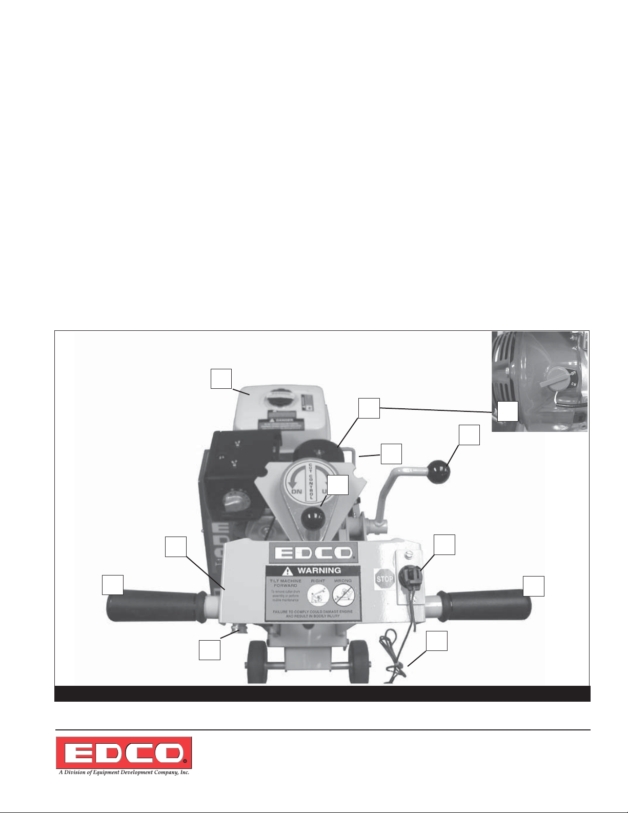
Operating Instructions
E-CPM-4-8-10-SL8-I-0309
1. Cutter Head Lever
2. Depth Control Knob
3. Emergency Stop Tether (CPM-10)
Stop button on (CPM-4 & CPM-8) *
4. Cushioned Handles
5. Ignition Switch (Position will vary) *
6. Throttle Control *
* Not on Electric models
NOTE: Controls are similar on all models.
8
7. Water Hook Up
8. Fuel Tank *
9. Emergency Stop Switch Lanyard
(CPM-10) *
10. Easy Lift Handle
11. Fuel Lockoff Solenoid Toggle
For Propane Models Only.
(Not Shown) *
5
5
1
10
2
6
4
3
4
9
7
Figure 2
100 Thomas Johnson Drive, Frederick, MD 21702-4600 USA
Phone (301) 663-1600 • 1-800-638-3326
Fax (301) 663-1607 • 1-800-447-3326
Website: www.edcoinc.com
Email: sales@edcoinc.com
Printed in USA
TVW ©2009
Page 5
E-CPM-4-8-10-SL8-I-0309
CPM-4-8-10-SACRALITE8 OPERATING INSTRUCTIONS
When using Hi-carbon steel or Tungsten Carbide cutter wheels:
IMPORTANT!
Read the engine manufacturer’s manual, familiarize yourself with engine start procedures.
BEFORE STARTING THE ENGINE: *Gasoline models only
Be sure that the cutter drum assembly has been properly installed and the cutter
drum shaft is in place and secured.
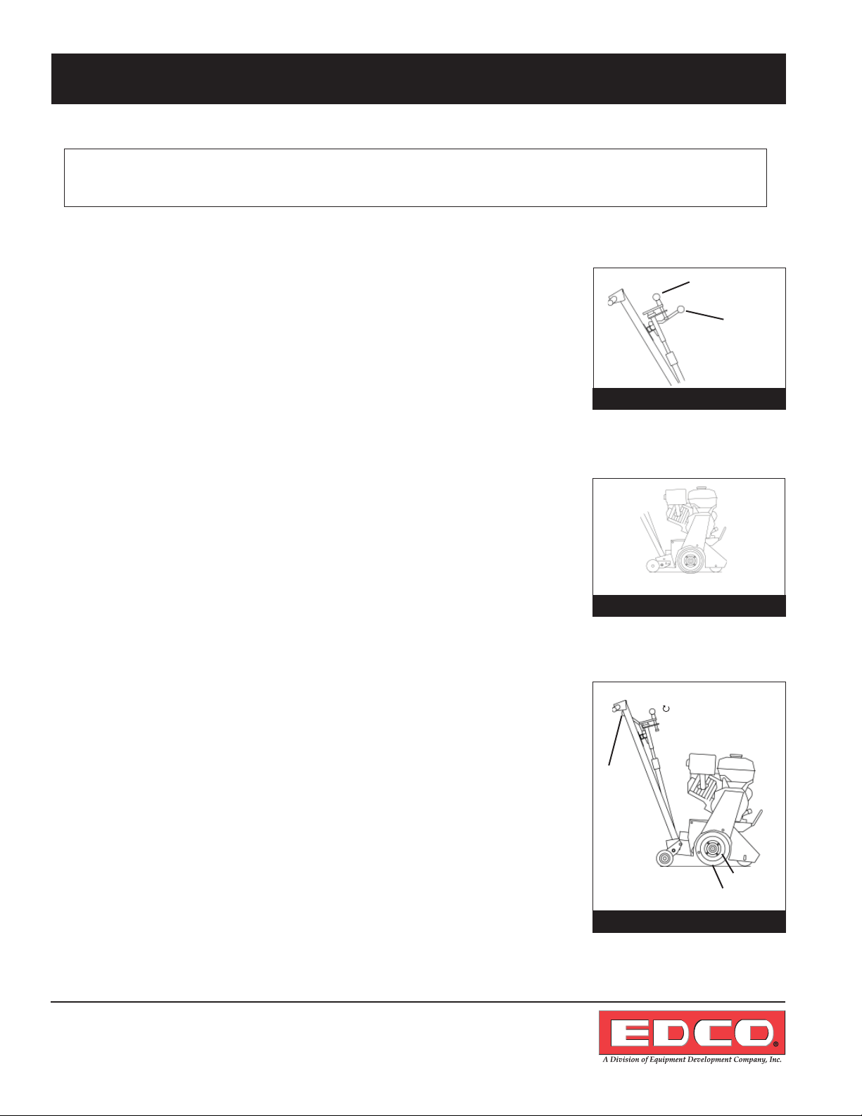
1. Select a level place at the job site. Set the “disengage lever” in the full DOWN
position. Refer to (Figure A).
It is most important to determine the position of the cutter wheels as they relate to
the slab or fl oor surface. If the drum assembly is fi lled with cutters, the cutter
wheels will most likely contact the slab when the “disengage lever” is lowered.
Refer to (Figure B).
Turn the “depth adjustment crank” UP until the cutter wheels are clear of the slab.
Refer to (Figure A). Follow these instructions each time before the engine is
started to prevent accidental damage to the slab.
Depth Adjustment Crank
Figure A
Disengage Lever
Full DOWN
Position
2. Raise the “disengage lever” to the full UP position. DO NOT force the lever. If
resistance is felt, turn the “depth adjustment crank” DOWN one or two turns.
This will allow the “disengage lever” to reach its normal full UP position. Refer to
(Figure C).
3. Check level of oil in engine crankcase (engines are usually shipped dry, oil must
be added as per engine manufacturers instructions). *
4. Check fuel level ( follow engine manufacturers instructions). *
5. Be sure all guards (belt, motor, cutter wheel) are in place and secure.
6. Vacuum hose port should have hose attached or cap installed to control dust
generated during the cutting operation.
7. Locate engine on/off switch, if the engine is so equipped. On some engines the
throttle control is also the engine shut-off switch. Familiarize yourself with this
operation. *
8. All EDCO gasoline engine operated planers are equipped with a STOP switch,
usually located on the handle. Use this switch for emergency engine shut-off. *
9. Cold engine starting: Be sure fuel line valve is open. Set choke (separate lever
on some engines - others have choke as part of throttle control). Open throttle
(full to engage choke) 3/4 to full on engines with a separate choke. Turn engine
ignition switch ON. Be sure emergency STOP switch is ON. *
Cutter Wheels Contacting Slab Surface
Figure B
Depth Adjustment Crank
UP
Disengage
Lever
UP
Position
Cutters Clear of Slab
Surface
Cutter Drum
Cutter Wheel
10. Before starting determine that the recoil starter assembly turns freely, starter
rope pulls easily and the rope retracts properly. *
100 Thomas Johnson Drive, Frederick, MD 21702-4600 USA
Printed in USA
TVW
©2009
Page 6
Phone (301) 663-1600 • 1-800-638-3326
Fax (301) 663-1607 • 1-800-447-3326
Website: www.edcoinc.com
Email: sales@edcoinc.com
Figure C
 Loading...