

Page 1

GMS-14
E-MS-GMS14&20-I-1002
Operator’s Instruction Manual
Masonry Saws
GMS-20
Shown with Optional Stand
MS-14
Shown with Optional Stand
MS-20
Gasoline and Electric
14” & 20” Masonry Saws
100 Thomas Johnson Drive, Frederick, MD 21702-4600 USA
Phone (301) 663-1600 • 1-800-638-3326
Fax (301) 663-1607 • 1-800-447-3326
Website: www.edcoinc.com • Email: [email protected]
Printed in USA
©2002
Page 1
Page 2

E-MS-GMS14&20-I-1002
READ AND UNDERSTAND THE OPERATORS INSTRUCTION MANUAL THOROUGHLY
BEFORE ATTEMPTING TO OPERATE THIS EQUIPMENT.
Death or serious injury could occur if this machine is used improperly.
SAFETY
SAFETY MESSAGES
MESSAGES
• Safety Instructions are proceeded by a graphic alert symbol of
DANGER, WARNING , or CAUTION.
Indicates an imminent hazard which, if not
avoided, will result in death or serious injury.
Indicates an imminent hazard which, if not
avoided, can result in death or serious injury.
Indicates hazards which, if not avoided, could
result in serious injury and or damage to the
equipment.
GASOLINE POWERED EQUIPMENT
Engine exhaust from this product contains
chemicals known to the State of California to
cause cancer, birth defects or other reproductive harm.
• Do not operate gasoline powered equipment without adequate
ventilation. Carbon monoxide is an invisible, odorless gas that
can kill.
Gasoline is extremely flammable and poisonous. It
should only be dispensed in well ventilated areas, and
with a cool engine.
ELECTRICAL POWERED EQUIPMENT
Extreme care must be taken when operating electric
models with water present: Ensure power cord is properly grounded, is attached to a Ground-Fault-Interrupter
(GFI) outlet, and is undamaged.
• Check all electrical cables - be sure connections are tight and
cable is continuous and in good condition. Be sure cable is
correctly rated for both the operating current and voltage of this
equipment.
• Improper connection of the equipment-grounding conductor
can result in a risk of electric shock. Check with qualified electrician or service person if there is any doubt as to whether the
outlet is properly grounded. Adhere to
ordinances.
• NOTE: In the event of a malfunction or breakdown, grounding
provides a path of least resistance for the electric current to
dissipate. The motor is equipped with a grounded plug and
must be connected to an outlet that is properly installed and
properly grounded. DO NOT modify the plug provided on the
motor. If the plug does not fit the outlet have a qualified electrician install the proper receptacle.
• Switch motor OFF
• Do not disconnect power by pulling cord. To disconnect, grasp
the plug, not the cord.
• Unplug power cord at the source and machine when not in use
and before servicing.
before disconnecting power.
all local codes and
GENERAL INSTRUCTIONS
• Equipment should only be operated by trained personnel in
good physical condition and mental health (not fatigued). The
operator and maintenance personnel must be physically able
to handle the bulk weight and power of this equipment.
• This is a one person tool. Maintain a safe operating distance to
other personnel. It is the
other people (workers, pedestrians, bystanders, etc.) away
during operation. Block off the work area in all directions with
roping, safety netting, etc. for a safe distance. Failure to do so
may result in others being injured by flying debris or exposing
them to harmful dust and noise.
• This equipment is intended for commercial use only.
• For the operator’s safety and the safety of others, always keep
all guards in place during operation.
• Never let equipment run unattended.
• Personal Protection Equipment and proper safety attire must
be worn when operating this machinery. The operator must
wear approved safety equipment appropriate for the job such
as hard hat and safety shoes when conditions require. Hearing protection MUST be used (operational noise levels of this
equipment may exceed 90db). Eye protection MUST be worn at
all times.
Keep body parts and loose clothing away from moving
parts. Failure to do so could result in dismemberment
or death.
• Do not modify the machine.
• Stop motor/engine when adjusting or servicing this equipment.
Maintain a safe operating distance from flammable
materials. Sparks from the cutting-action of this machine can ignite flammable materials or vapors.
operators’ responsibility to keep
DUST WARNING
Some dust created by power sanding, sawing,
grinding, drilling, and other construction activities contains chemicals known to cause cancer, birth defects, or other reproductive harm.
Some examples of these chemicals are:
• Lead from lead-based paints, and
• Crystalline silica from bricks and concrete and other
masonry products.
Your risk of exposure to these chemicals varies depending on
how often you do this type of work. To reduce your risk: work in a
well ventilated area, use a dust control system, such as an industrial-style vacuum, and wear approved personal safety equipment, such as a dust/particle respirator designed to filter out
microscopic particles.
Printed in USA
©2002
Page 2
100 Thomas Johnson Drive, Frederick, MD 21702-4600 USA
Phone (301) 663-1600 • 1-800-638-3326
Fax (301) 663-1607 • 1-800-447-3326
Website: www.edcoinc.com • Email: [email protected]
Page 3

E-MS-GMS14&20-I-1002
Equipment Instruction Manual
EDCO Model
Table of Contents
Section Page Number
Operator Controls ...........................................................................................................4-5
Safety Guidelines ....................................................................................................................6
Operating Instructions .....................................................................................................7-11
Maintenance ................................................................................................................12-14
Maintenance Schedule ..........................................................................................................15
Limited Equipment Warranty ......................................................................................back page
Width
Length
HOW TO ORDER REP AIR P ARTS
T o insure product safety and reliability , always
use genuine EDCO replacement parts when
making repairs to the equipment.
When ordering parts, please specify the
MODEL and SERIAL NUMBER of the machine
as given on the NAMEPLA TE. In addition, give
part number , description and quantity as listed
in the parts list.
Please note: Due to improvements and
changes in the equipment the illustrations
shown may be different from the actual machine.
T oll Free: V oice 1-800-638-3326
Fax 1-800-447-3326
Height
Model
Height
Width
Length
Weight
Width
Length
Figure 1
Specifications and dimensions are approximate
and subject to change.
MS-14
31”
78.7cm
18 3/8”
46.6cm
41 3/4”
106cm
170 lbs
77kg
GMS-14
43”
109cm
18 1/2”
47cm
41 3/4”
106cm
208 lbs
94.3kg
440 lbs
MS-20
63 1/2”
162cm
26 1/2”
67.3cm
52”
132cm
200kg
Height
GMS-20
77”
195.6cm
27”
68.6cm
58”
147.3cm
480 lbs
218 kg
100 Thomas Johnson Drive, Frederick, MD 21702-4600 USA
Phone (301) 663-1600 • 1-800-638-3326
Fax (301) 663-1607 • 1-800-447-3326
Website: www.edcoinc.com • Email: [email protected]
Printed in USA
©2002
Page 3
Page 4

E-MS-GMS14&20-I-1002
GMS-14 (Figure 2) & GMS- 20 (Figure 3)
A Air Filter
B. Fuel T ank
C. On/Off Switch
D. Water Pump Belt Guard
E. Oil Dip Stick
F. Handle
G . Blade Guard
H. Blade Guard Lock
I. Submersable Water Pump
J. Water Tray Plug
K. Rolling T able
L. Angle Cutting Stop
M. Welded S teel Frame/Water T ray
N. Drive Belt Guard
O. Safety Cable
P . Cutting Head Lock
Q. Engine Throttle
R. Recoil Starter
S. Cutting Head Height Positioner
T . Foot Treadle
Operator Controls - GMS Models
Figure 2 (GMS-14)
Do not operate gasoline powered equipment
without adequate ventilation.
Carbon monoxide is an invisible,
odorless gas that can kill.
Printed in USA
©2002
Page 4
100 Thomas Johnson Drive, Frederick, MD 21702-4600 USA
Phone (301) 663-1600 • 1-800-638-3326
Fax (301) 663-1607 • 1-800-447-3326
Website: www.edcoinc.com • Email: [email protected]
Figure 3 (GMS-20)
Page 5

Operator Controls- MS Models
MS-14 (Figure 4) & MS-20 (Figure 5)
A. Handle
B. Motor
C. Reset Button
D. Voltage Selector Switch
E. Power Cord
F. Water Pick Up Hose
G . Water Tray Plug
H. Rolling T able
I. Angle Cutting Stop
J. Welded Steel Frame/Water Tray
K. Blade Guard
L. Drive Belt Guard
M. Blade Guard Lock
N. Motor Starter Box
O. Cutting Angle Lock
P . Cutting Head Height Positioner
Q. Foot Treadle
E-MS-GMS14&20-I-1002
Figure 4 (MS-14)
Electric motor must be properly grounded
at all times.
Figure 5 (MS-20)
100 Thomas Johnson Drive, Frederick, MD 21702-4600 USA
Phone (301) 663-1600 • 1-800-638-3326
Fax (301) 663-1607 • 1-800-447-3326
Website: www.edcoinc.com • Email: [email protected]
Printed in USA
©2002
Page 5
Page 6

E-MS-GMS14&20-I-1002
Read and understand this Operator’s Instruction Manual,
and the Engine Manufacturer’s Owner’s Manual
before operating this equipment.
Death of serious injury can result if this machine is used improperly.
Safety Guidelines
Eye and ear protection must be worn at all times while the saw is in use. During normal
operation, sound pressure levels exceed 92dBA. Use only ANSI approved safety glasses to
help prevent eye injury . S tandard eyeglasses have only impact resistant lenses; they are NOT
safety glasses.
Operator must wear appropriate clothing and footwear. Do not wear loose clothing or jewelry that
can get tangled in moving parts. Footwear should provide sure footing and protection from debris
that may be dropped. Take step s to insure hair will not be caught in moving part s. If necessary ,
tie it back.
• When loading or unloading the saw, use caution. Make sure rolling t able is locked so that the blade will not be
damaged. Do not move the saw while the engine is running.
• Never exceed the maximum operating speed of the blade. Match the blade speed rating with the arbor shaft speed.
(See page 1 1)
• Never leave the saw running unattended.
• Never operate this saw under the influence of drugs, alcohol or when taking medications that impair the senses or
reactions, or when excessively tired or under stress.
• Do not lend or rent this equipment without including the Operator’s Instruction Manual and the Engine Manufacturer’s
Manual.
• Make sure all safety decals can be clearly read and understood. Replace damaged or missing decals immediately .
For Electric Models:
• Electric motor must be properly grounded at all times. Check the outlet box to be sure the electrical service is
properly grounded and that adequate power is available. Insufficient power will cause motor to overheat and burn out.
Use only grounded extension cords correctly sized for the current draw and voltage drop (amp rating and length).
Never use frayed, damaged, taped or underrated extension cords. Electrical shock could result in death or serious
injury and damage to the equipment.
For Gasoline Models:
• Poisonous exhaust gas. Do not operate gasoline powered equipment without adequate ventilation. Carbon monoxide is an invisible, odorless gas that can kill. NEVER REFUEL AN ENGINE WHILE IT IS HOT OR AN ENGINE
WHILE IT IS RUNNING . Only refuel in a well-ventilated area and only refuel after the engine has cooled completely.
Thoroughly cleanup any spilled fuel before starting the engine.
Dry cutting creates a large volume of airborne dust. For health reasons, the operator should wear
an applicable respirator. The dust may cont ain chemicals known to cause serious illnesses, including Silicosis - a fatal disease of the lungs. Check the chemical properties of the material to be cut
and follow all EPA/OSHA regulations.
Safety warnings and guidelines do not by themselves eliminate danger.
They are not substitutes for proper accident prevention procedures and good judgement.
Printed in USA
©2002
Page 6
100 Thomas Johnson Drive, Frederick, MD 21702-4600 USA
Phone (301) 663-1600 • 1-800-638-3326
Fax (301) 663-1607 • 1-800-447-3326
Website: www.edcoinc.com • Email: [email protected]
Page 7

Operating Instructions
Before Starting:
• Read and understand the instructions supplied by the engine manufacturer.
• Familiarize yourself with all engine and saw controls. (Figures 2-5)
• Visually inspect the entire machine for damage or wear. Look for signs of oil or fuel
leaks. Remove excess dirt or debris. Check that all nuts, bolts and screws are tight.
Check for proper alignment of moving parts, possible binding of moving parts, breakage
of parts, loose mounting brackets, and any other condition that might affect operation.
E-MS-GMS14&20-I-1002
• Inspect diamond blade and arbor shaft. Check blades for cracks, loose segments,
worn or out-of-round arbor holes. Do not use warped, twisted, out-of-balance blades or
any blade of questionable condition. Refer to Rx for Diamond Blades.
• Install back splash shield (Figure 6 and 7).
Figure 6
On Gasoline Models:
• Gasoline models are shipped from the factory dry , meaning without oil or gasoline.
Both will need to be added before the unit is used. Check the Engine Manufacturer’s
Owner’s Manual for instructions on break-in, servicing and proper use of engine.
• Check engine oil. Make sure that it is at the proper level and that it is clean.
Note: Some engines have an Oil Alert System that will automatically stop the engine before the oil level falls below
the safe limit. T o avoid an unexpected shut down, check the oil level regularly during operation.
• Check the fuel level. Do not over fill fuel tank and never refuel a hot engine. If refueling is necessary during operation,
allow engine to cool down first.
Figure 7
On Electric Models:
• Electric masonry saws are shipped with a twist lock, grounded, male plug attached to the machine and a female
mating connector which a qualified licensed electrician should attach to a user-supplied extension cord. V erify
that the extension cord is sized appropriately for the electrical load and that it is properly grounded.
Use only 3 wire (single phase), 4 wire (three phase) grounded electrical
cables that are marked U.L. and/or C.S.A. approved.
• Inspect the power and extension cords for damage. Do not use if either cord is frayed or
showing signs of wear.
• Identify the electrical power requirements of the saw . The voltage requirement s of the
motor can be found on the motor data plate. For dual voltage models, be sure the voltage
selector switch position correctly matches the incoming power source and that it is
locked into the selected voltage position with the locking bolt. (Figure 8)
• V erify that the power switch is in the off position before plugging machine into the power
source.
100 Thomas Johnson Drive, Frederick, MD 21702-4600 USA
Phone (301) 663-1600 • 1-800-638-3326
Fax (301) 663-1607 • 1-800-447-3326
Website: www.edcoinc.com • Email: [email protected]
Figure 8
Printed in USA
©2002
Page 7
Page 8
E-MS-GMS14&20-I-1002
When Wet Cutting:
• Secure the drain plug and fill the tray with clean water.
On Gasoline Models:
GMS-20
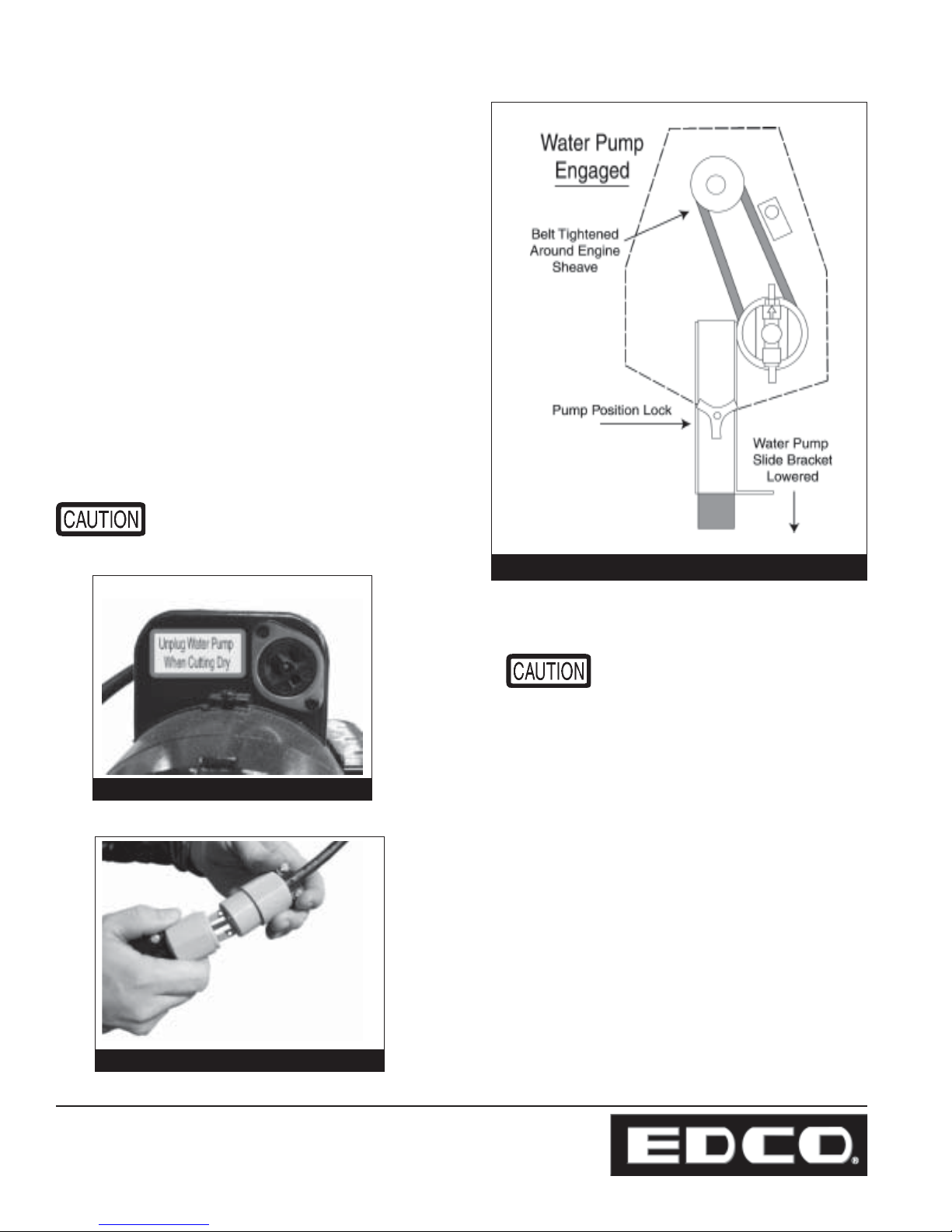
• Engage the water pump by loosening the pump
position lock, lower the water pump slide bracket and
retighten the pump position lock. (Figure 9)
• Prime the pump using the priming bulb. Pump the
bulb until water fills the clear plastic coolant hose from
the tray to the pump.
On Electric Models:
MS-14
• Plug submersible pump into the special outlet on the
motor. (Figure 10)
This outlet is intended for the water
pump only. Do not use it for any
other purpose.
Figure 9
Shows MS-14 Water Pump Outlet
Figure 10
(Shows MS-20
Water Pump Plug)
DO NOT LET THE
WA TER PUMP RUN DRY .
On All Models:
• The water in the tray must be kept clean. Running
dirty water through the system will cause damage.
• T o change the water , turn off the saw , remove the
plug in the bottom of the tray to drain water and
dispose of properly . Do not drain onto the surface
being worked on or other maintained surface because
staining will occur . Flush any loose grit and dirt out of
the tray . Replace drain plug and refill with clean
water. If water flow to the blade seems to be low,
check that strainer is clean and the water pump
pulley is properly engaged.
Figure 1 1
Printed in USA
©2002
Page 8
100 Thomas Johnson Drive, Frederick, MD 21702-4600 USA
Phone (301) 663-1600 • 1-800-638-3326
Fax (301) 663-1607 • 1-800-447-3326
Website: www.edcoinc.com • Email: [email protected]
Page 9
When Dry Cutting:
• Drain and flush any water or debris in the tray and
dispose of properly .
On Gasoline models:
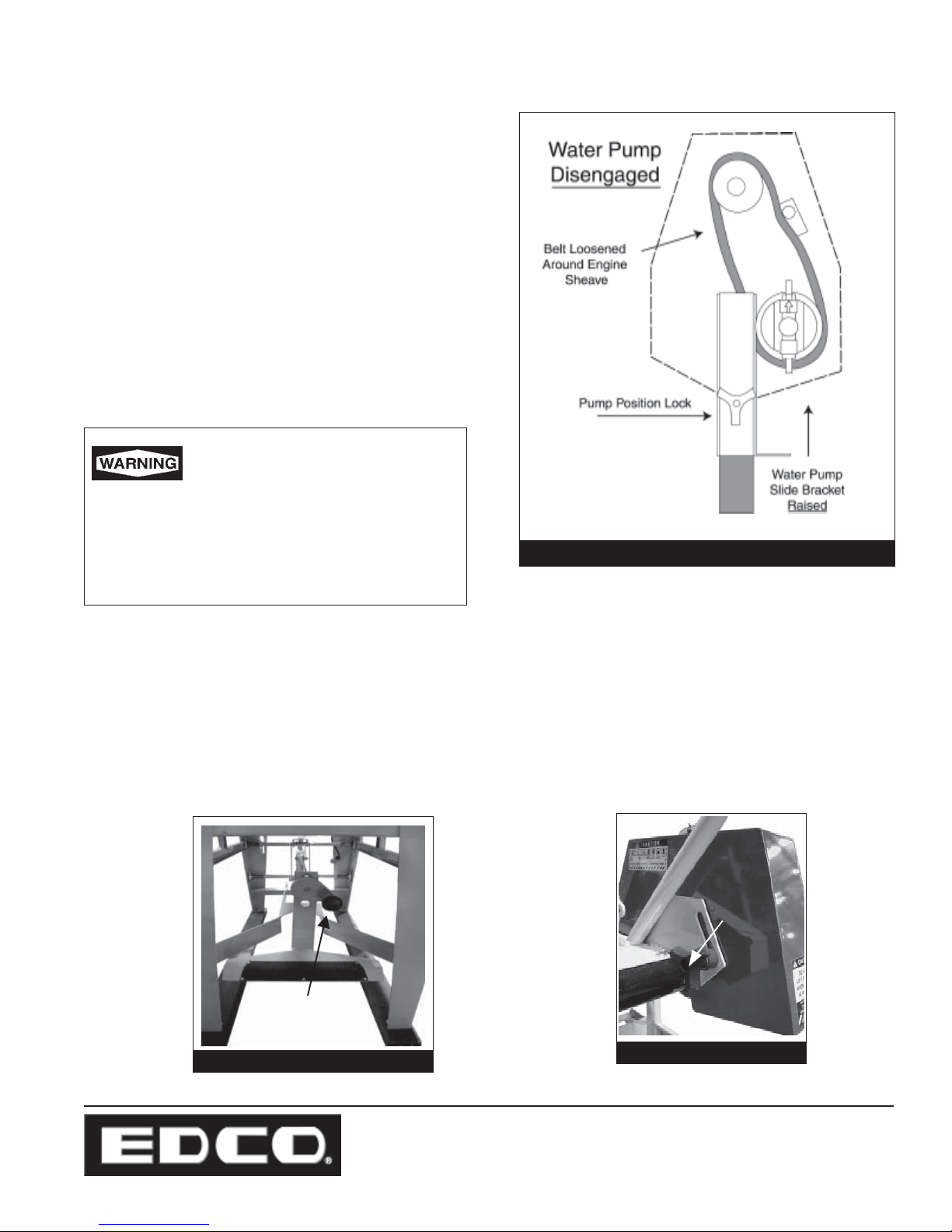
• Disengage water pump by loosening the pump position
lock. (Figure 12)
• Raise the water pump slide bracket to loosen belt
around the sheave. Loosen only enough to disengage
the unit, do not allow belt to slip off sheave.
• Retighten the pump position lock.
On Electric Models:
• Unplug the submersible pump from the motor.
Be careful when draining water
from tray and dispose of waste
away from work area.
E-MS-GMS14&20-I-1002
Draining the water directly to the ground will
cause a potentially serious working hazard including, but not limited to, risk from electric shock if
Figure 12
using an electric motor.
Pre-Set the Cut:
• When making a series of cuts at the same depth, set the cutting blade to the required depth by adjusting the
cutting head positioner. The cutting head will stay at the depth selected. (Figure 13)
• Use the blade lock to prevent changes in the depth setting caused by vibration.
Blade
Cover
Lock
Knob
Cutting Height
Adjustment Lock
Figure 13
Figure 14
100 Thomas Johnson Drive, Frederick, MD 21702-4600 USA
Phone (301) 663-1600 • 1-800-638-3326
Fax (301) 663-1607 • 1-800-447-3326
Website: www.edcoinc.com • Email: [email protected]
Printed in USA
©2002
Page 9
Page 10
E-MS-GMS14&20-I-1002
Starting the Engine:
• Be sure blade is clear of item to be cut.
• Determine that the recoil starter assembly turns freely , starter rope pulls easily, and the rope retracts properly .
• Follow the instructions supplied in the Engine Manufacturer’s Owner’s Manual for starting engine.
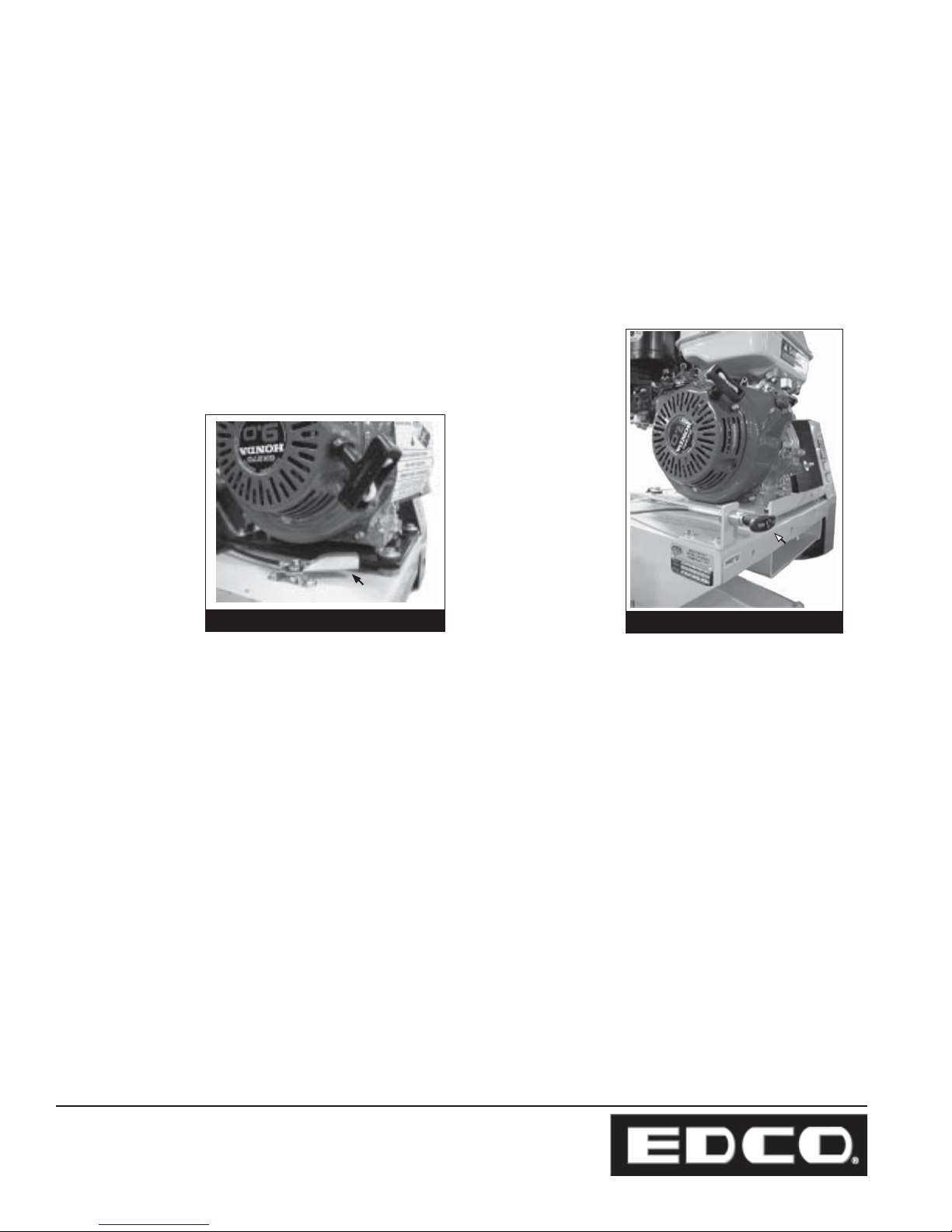
• Open the throttle and allow engine to reach operating temperature. Open throttle fully, do not use the throttle as a
means to match the arbor shaft speed to the specified blade speed requirements.
Be certain to use the proper blade for the machine.
Note: T o ensure that the necessary power is transferred to the blade, all cutting
must be done at full throttle. The governor is factory set for correct speed altering this setting may damage the machine. Maintain the engine according to
factory specifications.
Throttle
Throttle
Figure 15 ( GMS-14)
Figure 16 (GMS-20)
Throttle
Starting the Electric Motor:
REMINDER: On models equipped with a voltage selector switch, verify switch is set at the operating voltage available
at the job site and the locking bolt is in place. Motor burnout due to use of improper voltage will void the
warranty on the motor. (See Figure 8)
• Be sure blade is clear of the item to be cut.
• Turn on the motor .
• Listen for motor to reach operating speed. Do not use if motor hums or does not reach operating speed within a few
seconds. Motor hum may indicate a malfunction due to:
- Job site voltage may too low .
- An Internal motor problem.
- The blade may be jammed.
- Voltage selector switch in wrong position.
or
- The belts may be too tight.
Printed in USA
©2002
Page 10
100 Thomas Johnson Drive, Frederick, MD 21702-4600 USA
Phone (301) 663-1600 • 1-800-638-3326
Fax (301) 663-1607 • 1-800-447-3326
Website: www.edcoinc.com • Email: [email protected]
Page 11

E-MS-GMS14&20-I-1002
Cutting:
• Do not strain the engine/motor while cutting. Do not jam work piece into the blade. Do not twist the work piece while
cutting.
• When you have finished cutting:
On gasoline models: To stop engine, return throttle to idle. Stop the engine by turning the engine mounted stop
switch to the OFF position. Do not leave the saw running unattended.
On electric models: Depress the stop botton on the motor starter box. Wait until saw comes to a complete stop
before performing any type maintenance.
• Clean dust and debris from machine.
IMPORT ANT:
• When actually cutting masonry products, it is important that the blade is at it’s maximum RPM. DO NOT force or
jam the blade. Forcing the blade will cause the motor to overheat, tripping the overload device or severe motor
damage.
• Do not reach underneath or around work piece while the blade is rotating.
• Keep stable footing at all times while cutting.
• Keep hair, clothing, fingers and all body parts away from the blade and any other
moving parts.
Model
MS-14
GMS-14
MS-20
GMS-20
Diameter
Blade
14 inches
14 inches
20 inches
20 inches
Arbor Shaft
Figure 17
Rating
2600 RPM
2600 RPM
2400 RPM
2400 RPM
Max.
Cutting Depth
5 inches
5 inches
8 inches
8 inches
100 Thomas Johnson Drive, Frederick, MD 21702-4600 USA
Phone (301) 663-1600 • 1-800-638-3326
Fax (301) 663-1607 • 1-800-447-3326
Website: www.edcoinc.com • Email: [email protected]
Printed in USA
©2002
Page 11
Page 12

E-MS-GMS14&20-I-1002
Disconnect spark plug lead before performing
any maintenance on this machine.
Maintenance
Consult the Engine Manufacturer’s Owner’s Manual for more detailed engine maintenance instructions.
Changing the Blade:
• Inspect the new blade thoroughly before installing. Check for cracks, loose or missing segments, worn or out-of-
round arbor holes. Refer to the Rx for Diamond Blades pamphlet provided with your blade for more detailed informa-
tion on inspecting blades. Be sure the blade is appropriate for the job and matches the arbor speed and mounting
configuration on this saw. (Figure 17)
• Push the rolling table all the way to the back of the machine.
• Blade guard should be rotated all the way up and tightened into place.
Figure 18
• Remove blade cap and bolt. Carefully remove old blade.
• Inspect arbor shaft, backing plate and blade guard while blade is off.
Clean if dirty or replace if damaged or worn.
• Look for “direction of rotation” markings on the blade. (Usually an arrow
stamped on the blade.)
• Place new blade on the arbor shaft verifying that once installed the
markings on the blade follow the proper direction of rotation.
• Reinstall and tighten bolt using a SAE 1/2” wrench. Reinstall blade cap.
• Reposition blade guard and tighten. Reconnect spark plug lead. (if applicable)
Printed in USA
©2002
Page 12
100 Thomas Johnson Drive, Frederick, MD 21702-4600 USA
Phone (301) 663-1600 • 1-800-638-3326
Fax (301) 663-1607 • 1-800-447-3326
Website: www.edcoinc.com • Email: [email protected]
Page 13

E-MS-GMS14&20-I-1002
Belt Adjustment and Replacement:
• Periodically check belts for damage, same type and are at the proper tension. Do not mix belts. Slipping belts will
overheat causing the cutting speed to be limited and shorten the life of the belts. Over-tensioned belts will shorten the
life of the belts and bearings.
• On new equipment and after installing new belts of the same type, be certain to re-tension the belts after the first 4
hours of use. New belts are stiff and require a break in period. Belts that are loose could slip and/or overheat.
• Damaged, stretched or excessively worn belts should be replaced with a new complete set of belts of the same
type. Do not mix belts.
Important!
• Belts must be replaced as a complete set of the same type, do not mix
belts even if only one belt is showing wear.
• Blade must be realigned every time the belts are tensioned.
On Gasoline Models:
• Access belts from back of machine.
• Unlock belt guard and lift top portion out of the way .
Water pump and drive belts are now accessible.
• T o change water pump belt, follow “disengage”
instructions on page 9.
• T o change drive belts, loosen engine mount bolts and
adjust jacking bolt until belts can be removed.
On Electric Models:
Belt
Guard
Lock
Figure 19
Water
Pump
Belt
Drive Belts
Figure 20
• Loosen motor mounts (4)
(Figure 21)
• Loosen jacking bolt until belts
slide off sheave. (Figure 22)
• Replace with a new complete
set of belts of same type. Do
not mix belt types.
• Adjust jacking bolt to tension
belts.
• Retighten motor mount bolts.
Motor
Mount
Bolts
Figure 21
100 Thomas Johnson Drive, Frederick, MD 21702-4600 USA
Phone (301) 663-1600 • 1-800-638-3326
Fax (301) 663-1607 • 1-800-447-3326
Website: www.edcoinc.com • Email: [email protected]
Figure 22
Jacking
Bolt
Printed in USA
©2002
Page 13
Page 14
E-MS-GMS14&20-I-1002
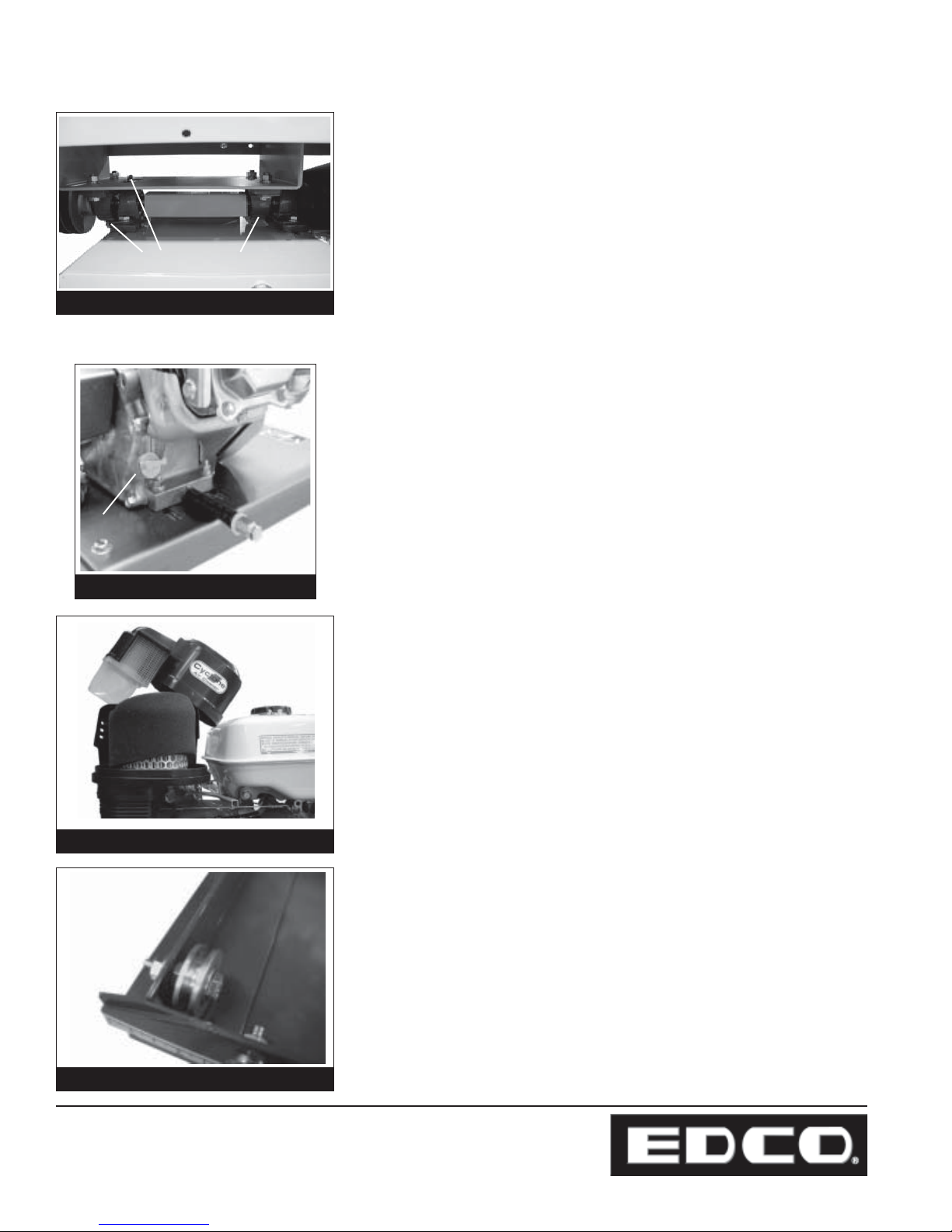
Grease Fittings
Figure 23
Grease Bearings:
• Drive shaft bearings must be greased every 4 hours.
(All are not visible in this photo)
Change Engine Oil:
• Check Engine Oil before each operation. Open the filler cap and look
at the dip stick. (Figure 24) Oil should be clearly visable both on the
stick and in the cavity and should look fairly clean. Running the
machine on dirty oil or when the oil is low will result in damage to
the engine.
Dip Stick
Figure 24
Figure 25
• Change the Engine Oil after every 50 hours of operation or sooner as
conditions require. Refer to the Engine Manufacturer’s Owner’s
Manual for specific viscosity recommendations and changing
instructions.
Inspect and Clean Air Filter:
(FIgure 25 shows Honda Cyclone Dual Filter style element).
• Refer to the Engine Manufacturer’s Owner’s Manual for instructions
on specific models.
• Check air filter at least once daily .
• Dirt build up on the filter will cause excessive engine wear.
Clean and Lubricate Wheels on Rolling Table and
Pivot Points on Front Treadle:
• During daily visual inspection, check to be sure the wheels on the
rolling table move smoothly and that there is no debris in the wheel
groove. (Figure 26)
Figure 26
Printed in USA
©2002
Page 14
100 Thomas Johnson Drive, Frederick, MD 21702-4600 USA
Phone (301) 663-1600 • 1-800-638-3326
Fax (301) 663-1607 • 1-800-447-3326
Website: www.edcoinc.com • Email: [email protected]
• Lubricate the wheels as necessary .
• Replace damaged or worn wheels.
Page 15

E-MS-GMS14&20-I-1002
1
1
1
1
1
1
1
1
1
1
1
1
1
1
1
1
1
1
1
Repairs are to be preformed
by EDCO or by approved
EDCO repair technicians.
Maintenance Schedule
23456789012345678901234567890
23456789012345678901234567890
23456789012345678901234567890
23456789012345678901234567890
23456789012345678901234567890
23456789012345678901234567890
23456789012345678901234567890
23456789012345678901234567890
23456789012345678901234567890
23456789012345678901234567890
23456789012345678901234567890
23456789012345678901234567890
23456789012345678901234567890
23456789012345678901234567890
23456789012345678901234567890
23456789012345678901234567890
23456789012345678901234567890
23456789012345678901234567890
23456789012345678901234567890
Visually Inspect Entire
Machine and Hardware
Check Engine Oil*
Inspect Blade and
Arbor Shaft
Inspect Guards
Before
Before each
Operation
Operation
X
X
X
X
Daily
Daily
Every 4 Hours
Every 4 Hours
Read and follow all instructions
in the Engine Manufacturer’s
Owner’s Manual.
Annually
Annually
of Operation
of Operation
Every 50 Hours
Every 50 Hours
As Required
As Required
Clean Air Filter Element*
Clean Dust and
Dirt Off Machine
Change Engine Oil*
Inspect Belts
Belt T ensioning
Lubricate Wheels
on Rolling T able
Replace Spark Plug*
Clean Water S trainer
Grease Bearings
X
X
X
X
X
X
X
X
X
*Gasoline Models Only
100 Thomas Johnson Drive, Frederick, MD 21702-4600 USA
Phone (301) 663-1600 • 1-800-638-3326
Fax (301) 663-1607 • 1-800-447-3326
Website: www.edcoinc.com • Email: [email protected]
Printed in USA
©2002
Page 15
Page 16

E-MS-GMS14&20-I-1002
LIMITED EQUIPMENT WARRANTY
Equipment Development Company, Inc. herein referred to as EDCO warrants that each new unit manufactured by EDCO to be free from defects in material
and workmanship in normal use and service for a period of (1) one year (except in the case of the cutter
drum assembly on all model concrete asphalt planes,
in which case the warranty period shall be 90 days)
from date of shipment to the original buyer or equipment rental center owner.
EDCO will, at its option, repair or replace, at the
EDCO factory or at a point designated by EDCO any
part, which shall appear to the satisfaction of EDCO
inspection to have been defective in material or workmanship.
This warranty , does not apply to failure occurring as a
result of abuse, misuse, negligent repairs, corrosion,
erosion, normal wear and tear, alterations or modifications made to the product without express written
consent of EDCO: or failure to follow the recommended operating practices and maintenance procedures as provided in the products operating and
maintenance manuals.
This warranty does not obligate EDCO to bear any
transportation charges in connection with the replacement or repair of defective parts. This warranty does
not obligate EDCO to bear any expense for travel time
or of personnel in connection with any service calls.
Accessories or equipment furnished and installed on
the product by EDCO but manufactured by others,
including but not limited to engines, motors, electrical equipment, transmissions, etc., shall carry the accessory manufacturers’ own warranty.
THIS WARRANTY IS IN LIEU OF ALL OTHER WARRANTIES, EXPRESSED OR IMPLIED, OR STATUTORY, INCLUDING ANY WARRANTIES OF MERCHANT ABILITY OR OF FITNESS FOR A PARTICULAR PURPOSE.
LIABILITY LIMITATIONS
The remedies of the user set forth under provisions
of warranty outlined above are the exclusive and total
liability of EDCO with the respect to their sale or the
equipment and service furnished hereunder, in conction with the performance or breach thereof, or from
the sale, delivery, installation, repair or technical direction covered by or furnished under the sale,
whether based on contract, warranty , negligence, indemnity, strict liability, or otherwise shall not exceed
the purchase price of the unit of equipment upon which
such liability is based.
EDCO will not in any event be liable to the user, any
successors in interest or any beneficiary or assignee
relating to this sale for any consequential, incidental,
indirect, special or punitive damages arising out of
this sale or any breach thereof, or any defects on, or
failure of, or malfunction of the equipment under this
sale based upon loss of use, lost profits or revenue,
interest, lost goodwill, work stoppage, impairment of
other goods, loss by reason of shutdown or nonoperation, increased expenses of operation of the
equipment, cost of purchase or replacement power
of claims of users or customers of the user for service interruption whether or not such loss or damage
is based on contract, warranty, negligence, indemnity , strict liability, or otherwise.
EDCO reserves the right to modify , alter and improve
any part or parts without incurring any obligation to
replace any part or parts previously sold without such
modified, altered or improved part or parts.
No person is authorized to give any other warranty or
to assume any additional obligation on EDCO’s behalf unless made in writing and signed by an officer of
EDCO.
Equipment Development Company, Inc.
USE ONLY GENUINE EDCO PARTS AND ACCESSORIES
For your own safety, the safety of others and the life of your machine
Printed in USA
©2002
Page 16
100 Thomas Johnson Drive, Frederick, MD 21702-4600 USA
Phone (301) 663-1600 • 1-800-638-3326
Fax (301) 663-1607 • 1-800-447-3326
Website: www.edcoinc.com • Email: [email protected]
 Loading...