

1

About This Manual
P/N:01.54.458126
MPN: 01.54.458126010
Release Date: March, 2019
© Copyright EDAN INSTRUMENTS, INC. 2019
This User Manual applies to 1.0X releases for Acclarix LX9 series Diagnostic Ultrasound Systems
including Acclarix LX9, Acclarix LX9 Exp, Acclarix LX9 Super, Acclarix LX85 and Acclarix LX88. See
Appendix A.9 for the difference between these models.
This User Manual Basic Volume together with the User Manual Advanced Volume (P/N: 01.54.458127)
contain necessary and sufficient information to use the Acclarix LX9 Series Diagnostic Ultrasound
Systems safely for the intended purposes and approved clinical applications.
Please read and make sure you understand all of the instructions in this manual prior to using the
system. Disregarding instructions, particularly warnings and cautions, is considered abnormal use.
Not all measurements and features are available for all system models and configurations. This
manual is based on the complete set of transducers and features available. Therefore, some of the
contents may not apply to your product. If you have any questions, please contact your local EDAN
representative. The pictures and interfaces in this manual are for reference only.
Conventions
In this manual, the following conventions are used to describe the system for better understanding:
Bold: bold texts indicate keys or items on main screen or touch screen.
<Bold>: bold texts in angular brackets indicate buttons, knobs and other controls on the console
or on the keyboard.
->: Arrow indicates operations following the path.
Contact Information:
For sales or service information please contact your local distributor or the EDAN service department
at: support@edan.com.cn
I

Contents
1 Introduction .................................................................................................................................. 1
1.1 Intended Use/ Indications for Use .............................................................................................. 1
1.2 Contra-indications ...................................................................................................................... 1
1.3 Device Description ..................................................................................................................... 1
2 Safety ............................................................................................................................................ 2
2.1 Warnings .................................................................................................................................... 2
2.2 Cautions ................................................................................................ ..................................... 4
2.3 Labeling Symbols ....................................................................................................................... 7
3 Getting Started ........................................................................................................................... 11
3.1 System Configuration ............................................................................................................... 11
3.2 System Overview ..................................................................................................................... 13
3.2.1. Main Unit........................................................................................................................ 13
3.2.2. Control Panel ................................................................................................................. 17
3.2.3. Screen Layout ................................................................................................................ 21
3.2.1. Touch Screen ................................................................................................................... 24
3.2.4. Trackball ........................................................................................................................ 26
3.3 System Preparation .................................................................................................................. 27
3.3.1. Battery Use ....................................................................................................................... 27
3.3.2. AC Power Use .................................................................................................................. 29
3.3.3. Transducer Connection .................................................................................................... 29
3.3.4. Powering on/ off ............................................................................................................... 30
3.4 Monitor Position Adjustment ..................................................................................................... 31
3.5 Control Panel Position Adjustment ........................................................................................... 34
4 Exam Operation ......................................................................................................................... 36
4.1 How to Start an Exam ............................................................................................................... 36
4.2 How to End an Exam ................................................................................................................ 37
4.3 How to Restart an Exam ........................................................................................................... 37
4.4 The Patient Information Page ................................................................................................... 37
4.5 Modality Worklist ...................................................................................................................... 39
5 Imaging ....................................................................................................................................... 41
5.1 B-mode ..................................................................................................................................... 41
5.1.1. Using B-mode ................................................................................................................... 41
5.1.2. B-mode Image Optimization ............................................................................................. 41
5.2 Color Mode ............................................................................................................................... 45
5.2.1. Color Mode Variants ......................................................................................................... 45
5.2.2. Using Color Mode ............................................................................................................. 45
5.2.3. Color Image Optimization ................................................................................................. 45
5.3 PW Mode .................................................................................................................................. 48
5.3.1. Using PW Mode ............................................................................................................... 48
II

5.3.2. PW Image Optimization ................................ ................................ .................................... 48
5.3.3. HPRF ............................................................................................................................... 51
5.4 CW Mode ................................................................................................................................. 51
5.4.1. Using CW Mode ............................................................................................................... 51
5.4.2. CW Image Optimization.................................................................................................... 51
5.5 M Mode .................................................................................................................................... 53
5.5.1. Using M Mode .................................................................................................................. 53
5.5.2. M-mode Image Optimization ............................................................................................ 53
5.6 Anatomic M Mode ..................................................................................................................... 55
5.6.1. Using Anatomic M Mode................................................................................................... 55
5.6.2. Anatomic M Image Optimization ....................................................................................... 55
5.7 Color M Mode ........................................................................................................................... 56
5.7.1. Using Color M Mode ......................................................................................................... 56
5.7.2. Color M Image Optimization ............................................................................................. 56
5.8 TDI Mode .................................................................................................................................. 57
5.8.1. TDI Mode Operations ....................................................................................................... 57
5.8.2. TDI Touch Screen Controls .............................................................................................. 57
5.9 3D/4D Mode ............................................................................................................................. 58
5.9.1. Pre-3D/Pre-4D .................................................................................................................. 58
5.9.2. 3D Volume Sweeping ....................................................................................................... 59
5.9.3. 3D Image Review ............................................................................................................. 60
5.9.4. 4D Volume Acquisition ...................................................................................................... 64
5.9.5. 4D Live Volume ................................................................................................................ 64
5.9.6. 4D Cine ............................................................................................................................ 65
5.9.7. Knobs and Buttons on Control Panel ............................................................................... 66
5.10 Panorama ............................................................................................................................... 67
5.11 Elastography ........................................................................................................................... 68
5.11.1. Using Elastography Mode ............................................................................................... 68
5.11.2. Elastography Image Optimization ................................................................................... 69
5.12 Contrast Imaging .................................................................................................................... 70
5.12.1. Using Contrast Imaging .................................................................................................. 71
5.12.2. Touch Screen Controls ................................................................................................... 71
5.12.3. Time Intensity Curve (TIC) Analysis ............................................................................... 73
5.13 ECG ........................................................................................................................................ 76
5.13.1. ECG Touch Screen Controls .......................................................................................... 77
5.13.2. ECG Basic Operations ................................................................................................... 77
5.13.3. ECG Review ................................................................................................................... 78
6 Transducers and Biopsy ........................................................................................................... 79
6.1 Transducer Model ..................................................................................................................... 79
6.2 Using Transducers.................................................................................................................... 81
III

6.3 Transducer Cleaning and Disinfecting ...................................................................................... 84
6.3.1. Cleaning ........................................................................................................................... 84
6.3.2. Disinfection ....................................................................................................................... 84
6.3.3. Sterilization ....................................................................................................................... 87
6.3.4. Storage ................................ ................................................................ ............................. 87
6.4 Needle Biopsy Guide ................................................................................................................ 88
6.4.1. Installing Needle Guide Bracket ....................................................................................... 88
6.4.2. Activating Needle Guide Function .................................................................................... 94
6.4.3. To Adjust the Needle Guide Line ...................................................................................... 94
6.5 Needle Visualization ................................................................................................................. 95
6.6 Center Line ............................................................................................................................... 96
6.7 Needle Guide Bracket Cleaning and Sterilization ..................................................................... 96
6.7.1. Cleaning ........................................................................................................................... 97
6.7.2. Sterilization ....................................................................................................................... 97
6.7.3. Storage ................................ ................................................................ ............................. 97
7 Features ...................................................................................................................................... 98
7.1 Comments ................................................................................................................................ 98
7.2 Body Mark .............................................................................................................................. 100
7.3 Split Display ............................................................................................................................ 101
7.3.1. Dual Imaging .................................................................................................................. 101
7.3.2. Quad Imaging ................................................................................................................. 101
7.4 Zoom ...................................................................................................................................... 102
7.4.1. Pan Zoom ....................................................................................................................... 102
7.4.2. Spot Zoom ...................................................................................................................... 102
8 Measurements and Reports .................................................................................................... 103
8.1 Generic Measurements .......................................................................................................... 107
8.1.1. B-mode Generic Measurements ..................................................................................... 107
8.1.2. M-mode Generic Measurements .................................................................................... 110
8.1.3. Strip Doppler Generic Measurements ............................................................................ 112
8.2 Application Measurements ..................................................................................................... 116
8.2.1. Abdomen Measurements................................................................................................ 117
8.2.2. Gynecology Measurements ............................................................................................ 118
8.2.3. Obstetrics Measurements............................................................................................... 119
8.2.4. Cardiac Measurements .................................................................................................. 123
8.2.5. Small Parts Measurements ............................................................................................ 127
8.2.6. Urology Measurements .................................................................................................. 128
8.2.7. Vascular Measurements ................................ ................................ ................................. 129
8.2.8. Pediatric Measurements ................................................................................................. 132
8.3 Worksheet and Report ............................................................................................................ 134
8.3.1. Worksheet ...................................................................................................................... 134
IV

8.3.2. Report ............................................................................................................................ 139
8.4 Measurement Accuracy .......................................................................................................... 140
9 Exam Data Management .......................................................................................................... 141
9.1 Storing Images ....................................................................................................................... 141
9.2 Reviewing Images .................................................................................................................. 142
9.3 Exam Database ...................................................................................................................... 143
9.4 Archiving Studies .................................................................................................................... 146
9.5 Structured Report ................................................................................................................... 146
10 Presets ...................................................................................................................................... 147
10.1 Preset Organization .............................................................................................................. 147
10.2 Selecting a Preset ................................................................................................................ 148
10.3 Storing and Editing a Preset ................................................................................................. 148
10.3.1. Exam Preset ................................................................................................................. 149
10.3.2. Comment Preset .......................................................................................................... 151
10.3.3. Body Mark Preset ......................................................................................................... 152
10.4 Measure Presets .................................................................................................................. 154
10.4.1. General Set-up ............................................................................................................. 154
10.4.2. Application Parameter .................................................................................................. 155
10.4.3. Measure Presets .......................................................................................................... 156
10.4.4. Report Set-up ............................................................................................................... 157
11 Utilities ...................................................................................................................................... 158
11.1 System Set-up ...................................................................................................................... 158
11.1.1. General Set-up ............................................................................................................. 158
11.1.2. Patient Set-up ............................................................................................................... 160
11.1.3. Store/Print Set-up ......................................................................................................... 161
11.1.4. Miscellaneous Set-up ................................................................................................... 162
11.1.5. User Set-up .................................................................................................................. 163
11.2 Connectivity .......................................................................................................................... 164
11.2.1. TCP/IP .......................................................................................................................... 165
11.2.2. DICOM .......................................................................................................................... 166
11.2.3. Network Store ............................................................................................................... 170
11.3 Maintenance ......................................................................................................................... 171
11.3.1. License ......................................................................................................................... 171
11.3.2. Version .......................................................................................................................... 171
11.3.3. Demo ................................................................................................ ............................ 172
11.3.4. Export/Import ................................................................................................................ 172
11.4 Screen Adjust........................................................................................................................ 173
12 In Between Exams ................................................................................................................... 174
12.1 Unpacking ............................................................................................................................ 174
12.2 Transport .............................................................................................................................. 174
V

12.3 Storage ................................................................................................................................. 174
13 Troubleshooting and Maintenance ......................................................................................... 175
13.1 Daily Checklist ...................................................................................................................... 175
13.2 Troubleshooting .................................................................................................................... 175
13.3 Cleaning and Disinfecting the System .................................................................................. 176
13.3.1. Cleaning and Disinfecting the System Surface ............................................................. 177
13.3.2. Cleaning and Disinfecting the ECG Cable .................................................................... 179
13.4 Maintenance ......................................................................................................................... 180
Appendix A Specifications ............................................................................................................ 181
A.1 Electrical Safety Classifications ........................................................................................... 181
A.2 Power Supply ...................................................................................................................... 181
A.3 Battery ................................................................................................................................. 181
A.4 Machine Specifications ........................................................................................................ 182
A.5 Display Specifications ......................................................................................................... 182
A.6 Technical Specifications ...................................................................................................... 182
A.7 Operating, Storage and Transportation Environment .......................................................... 184
A.7.1 Operating Environment ................................................................................................ 184
A.7.2 Storage and Transportation Environment .................................................................... 184
A.8 Transducer Specifications ................................................................................................... 184
A.9 Configuration Difference ...................................................................................................... 185
Appendix B Ultrasound Intensity and Safety ............................................................................... 186
B.1 Ultrasound in Medicine ........................................................................................................ 186
B.2 Ultrasound Safety and the ALARA Principle ........................................................................ 186
B.3 Explanation of MI/TI ............................................................................................................ 187
B.3.1 MI (Mechanical Index) ................................................................................................. 187
B.3.2 TI (Thermal Index) ....................................................................................................... 187
B.3.3 Display of MI/TI ............................................................................................................ 188
B.4 Acoustic Output ................................................................................................................... 188
B.4.1 Factors that Contribute to Uncertainty in the Output Display ....................................... 188
B.4.2 Differences between Actual and Displayed MI/TI ......................................................... 188
B.4.3 Measurement Uncertainty ............................................................................................ 188
B.4.4 Acoustic Power Default Settings .................................................................................. 189
B.5 Operator Control Features ................................................................................................... 189
B.6 Prudent Use Statement ....................................................................................................... 189
B.7 References for Acoustic Output and Safety ......................................................................... 189
B.8 Transducer Acoustic Output Data ........................................................................................ 190
Appendix C Order List ................................................................................................................... 191
Appendix D EMC Information ........................................................................................................ 193
Appendix E Ultrasound Gel Warmer ................................ ................................ ............................. 198
VI

Acclarix LX9 Series Diagnostic Ultrasound System User Manual Introduction
1 Introduction
1.1 Intended Use/ Indications for Use
The Acclarix LX9 series Diagnostic Ultrasound System is intended for use by a qualified physician or
allied health professional for ultrasound evaluations in hospitals and clinics. Clinical applications
include:
Abdominal
Gynecology
Obstetric
Cardiac
Small parts
Urology
Musculoskeletal
Peripheral vascular
Intra-operative
Pediatric
Neonatal
Adult Cephalic
1.2 Contra-indications
The Acclarix LX9 series Diagnostic Ultrasound System is not intended for ophthalmic use or any use
causing the acoustic beam to pass through the eye.
1.3 Device Description
The Diagnostic Ultrasound System consists of a main system and associated ultrasound transducers.
The system circuitry generates an electronic voltage pulse, which is transmitted to the transducer. In
the transducer, a piezoelectric array converts the electronic pulse into an ultrasonic pressure wave.
When coupled to the body, the pressure wave transmits through body tissues. The waves are then
reflected within the body and detected by the transducer, which then converts the waves back to an
electrical signal. The system then analyzes the returned signals and generates an ultrasound image
or spectral Doppler display.
The Diagnostic Ultrasound System provides the operator the ability to measure anatomical structures,
and offers analysis packages that provide information used by competent health care professionals to
make a diagnosis.
The system‟s user interface provides both hard keys for functions frequently used throughout an exam
and touch screen controls for mode-specific functions.
- 1 -

Acclarix LX9 Series Diagnostic Ultrasound System User Manual Safety
2 Safety
Throughout this document the following terms are used:
Warning: Advises against certain actions or situations that could result in personal injury or
death.
Caution: Advises against actions or situations that could damage equipment, produce
inaccurate data, or invalidate a procedure.
Note: Provides useful information regarding a function or a procedure.
Please read all warnings and cautions prior to using the system. For your convenience, all warnings
and cautions are provided in this section, but may be duplicated elsewhere in this document in the
context of the instructions for use.
2.1 Warnings
Only use Edan supplied power cord.
Only use Edan supplied battery. Read and understand the battery installation instructions prior
to changing the battery.
Only use Edan supplied transducer. Use of other transducers may result in electric shock or
system malfunction.
Only use a hospital grade, grounded, power outlet and plug. Do not use with an ungrounded
outlet.
The system is ordinary equipment (Sealed equipment without liquid proof). The transducers
(not including the transducer connector) are IPX7 certified. The footswitch is IP68 certified. Do
not immerse or expose any of the parts to extended moisture. Splash resistance does not
extend to transducer connectors. Please keep connectors dry.
Do not use in a wet environment or when the relative humidity exceeds 95%.
Do not reverse the positive and negative poles when installing the battery.
Do not use the battery near heat sources or when the ambient temperature is over 40oC. Do
not heat or dispose of in fire.
Do not destroy the battery; do not pierce or cause a strong impact to the battery.
Do not touch the connector pins on the transducer port.
Parts and accessories used must meet the requirements of the applicable IEC/EN60601
series safety standards, and/or the system configuration must meet the requirements of the
IEC/EN60601-1.
Use protective barriers (gloves and transducer sheaths) whenever possible. Follow sterile
procedures when appropriate. Thoroughly clean Transducers and reusable accessories after
each patient examination and disinfect or sterilize as needed. Refer to transducer use and
care instructions. Follow all infection control policies established by your office, department or
institution as they apply to personnel and equipment.
Not intended for Ophthalmic use.
If a sterile transducer cover becomes compromised during an intra-operative application
involving a patient with transmissible spongiform encephalopathy, such as Creutzfeldt-Jakob
disease, follow the guidelines of the U.S. Disease Control Center and this document from the
World Health Organization: WHO/CDS/APH/2000/3, WHO Infection Control Guidelines for
- 2 -

Acclarix LX9 Series Diagnostic Ultrasound System User Manual Safety
Transmissible Spongiform Encephalopathies. The transducers for your system cannot be
decontaminated using a heat process.
Contact with natural rubber latex may lead to a severe anaphylactic reaction in persons
sensitive to the natural latex protein, Sensitive users and patients must avoid contact with
these items. EDAN strongly recommends that health-care professionals identify their
latex-sensitive patients, and refer to the March 29, 1991 Medical Alert on Latex products. Be
prepared to treat allergic reactions immediately.
Improper operation may cause the internal lithium battery (hereinafter called battery) to
become hot, ignited or possibly explode, and it may lead to decreased battery capacity. It is
necessary to read the user manual instructions and warning messages carefully.
Do not touch accessible contacts of electrical equipment and the patient simultaneously.
This device is not suitable for intra-cardiac use or direct cardiac contact.
The system shall not be serviced or maintained while in use with a patient.
Install the system according the EMC guidance provided in Appendix D
Do not stack the system on other electronic equipment.
The use of transducer and connecting cable not supplied by EDAN may result in increased
emissions or decreased immunity of the equipment.
Refer to Appendix D for recommended separation distances from other equipment, including
portable and RF communication devices.
The mains plug is used to isolate the system from main power. Position the system so that it is
easy to disconnect it from the power supply.
No modification of this equipment is allowed.
The system should be maintained regularly, at least annually, by a qualified technician who
has adequate training, knowledge and experience. That person should be familiar with the
Service Manual, available from your Edan representative.
Keep non-medical equipment out of the vicinity of the patient. (1.5m/6ft.)
Use of an extension cord or multi-socket outlet setup to provide power to the ultrasound
system or to the system‟s peripheral devices, may compromise the system grounding and
cause the system to exceed current leakage limits.
It is not suggested to use a multiple socket-outlet with the device. If one is required, make sure
that the multi-socket complies with the requirement specified in Chapter 16 of IEC 60601-1, or
the multi-socket is with an isolation transformer. And the multi-socket shall not be placed on
the floor.
SHOCK HAZARD - Don't connect electrical equipment, which has not been supplied as a part
of the system, to the multiple portable socket-outlet supplying the system.
SHOCK HAZARD - Don't connect non-electrical equipment, which has been supplied as a part
of the system, directly to the wall outlet when the non-medical equipment is intended to be
supplied by a multiple portable socket-outlet with an isolation transformer.
Edan recommends the use of isolated connectors on any electrical equipment attached to the
system, and/or using isolation transformers that comply with IEC60601-1 to power that
electrical equipment.
Always use sterile technique during a biopsy procedure. Sterilize the needle guide assembly
between uses.
- 3 -

Acclarix LX9 Series Diagnostic Ultrasound System User Manual Safety
Use a sterile needle with each use.
The system may be interfered with by other equipment, even if that other equipment complies
with CISPR EMISSION requirements.
The system cannot be used together with high-frequency surgical equipment.
Remove the battery from the device when the device is not used for a long time.
Transducer Warnings
To avoid infection, always use protective gloves when cleaning or disinfecting
Read and follow all manufacturer instructions for disinfection agents.
To avoid infection, ensure that expiration date of the disinfecting solution has not passed.
Disinfect the transducer after each intra-cavity or intra-operative procedure. Use a new sterile
sheath for each such procedure.
Use a pyrogen-free transducer sheath for intra-operative procedures.
The system is not intended to come into contact with the central nervous system and central
cardiovascular system.
Unplug the transducer from the system prior to cleaning or disinfecting.
Do not immerse the transducer beyond the point indicated in Figure 6-3.
Do not allow the transducer connector to get wet.
"Intra-operation" exam preset must be used when doing intra-operative examination using
transducer L17-7SQ.
2.2 Cautions
Excessive dust and dirt could clog internal airflow and cause overheating. Do not use in a
dusty environment.
Do not use a battery that leaks, emits an odor, appears deformed, or discolored. Immediately
replace it with a new Edan-supplied battery and dispose of the old battery according to local
regulations. Replace a battery that has reached the end of its service life.
Use care when storing or disposing of batteries. Do not allow the leakage from one battery to
come in contact with other batteries. Batteries (including button cell on the main board) are
hazardous waste. Do not dispose of them together with household garbage. At the end of their
life hand the batteries over to the applicable collection points for the recycling of waste
batteries. Inappropriate disposal of waste may contaminate the environment.
Inspect the system regularly, at least weekly. Before use ensure there is no visible evidence of
damage to the equipment, cables, and transducers. If a component is damaged, replace it
before use.
Do not use in locations subject to vibration.
Do not exert excessive vibrations onto the system. Otherwise, it may damage the mechanical
components (such as wheels). If the system is required to move on an uneven surface
frequently, consult EDAN or authorized representatives for service.
Read and understand the
using the system. Do not expose a patient to ultrasound energy longer than clinically
reasonable.
Practice ALARA principle when operating ultrasound system. Minimize the acoustic power
Appendix B.2 Ultrasound Safety and the ALARA Principle
- 4 -
before

Acclarix LX9 Series Diagnostic Ultrasound System User Manual Safety
without compromising the image quality.
Do not use in the presence of a flammable anesthetic.
The system generates radio frequency energy, which may cause interference with other
devices in the vicinity. If interference is suspected, try re-orienting or relocating the equipment.
The use of electrosurgical units or other devices that generate radio frequency interference
may cause image distortion or other malfunctions.
The system should only be used by a qualified physician or allied health professional for
ultrasound evaluations.
Use only Edan supplied or recommended parts and accessories.
Verify measurement results prior to entering them into a report.
Contact your local distributor or Edan Service if there is excessive noise from the system
speaker or fans.
Please read and understand cleaning instructions prior to use.
Please read and understand maintenance instructions prior to use.
Please read and understand instructions for system operation prior to use.
Studies stored on the system hard drive should be archived regularly. The system is not
intended for long term storage of patient information. Confirm successful archiving before
deleting a study from the hard drive.
Ensure that the system vents are clear and unobstructed.
Confirm patient identification information prior to storing or printing any exam information.
If you have any question about maintenance, technical specifications, or system functionality,
please contact your local distributor or Edan Service at: support@edan.com.cn
Ultrasound images occasionally have artifacts, and should only be used as one part of an
overall clinical assessment.
To avoid electrical shock, turn off and disconnect the device from the AC power source before
cleaning and disinfecting.
No user serviceable parts are inside the system. All repairs on the system must be performed
by EDAN certified service personnel.
The device and accessories are to be disposed of according to local regulations after their
useful lives. Alternatively, they can be returned to the dealer or the manufacturer for recycling
or proper disposal.
The packaging is to be disposed of according to local or hospital‟s regulations; otherwise, it
may cause environmental contamination. Place the packaging at the location that is
inaccessible to children.
Properly dispose of used cleaning agents or disinfectants according to your hospital's
regulation.
The system does not need calibration as part of routine maintenance.
The format of U disk should be FAT32.
Do NOT place the device on slopes. It may suddenly slide, resulting in injury and/or equipment
damage.
Do NOT stand/sit on or bend over the device. It may move and make you lose your balance
and tumble.
- 5 -

Acclarix LX9 Series Diagnostic Ultrasound System User Manual Safety
To ensure safety, two persons are required to move the device across slopes.
Transducer Cautions
Do not use disinfection agents beyond their expiration date.
Do not use sterile sheaths beyond their expiration date.
Inspect the transducer connector, cable, and head periodically. Do not use if there is evidence
of excessive wear or damage.
Do not operate the transducer to temperatures in excess of 40°C or store the transducer in
temperatures in excess of 55°C.
Do not kink or pull on the transducer cable.
Broken or bent connector pins can cause image artifacts. Do not use a transducer with broken
or bent pins.
Network Security Cautions
Keep your ultrasound system safe to protect the patient information and data from being
modified, damaged or disclosed caused by unauthorized disassembly.
Always ensure the privacy of patient information and data displayed/stored in the ultrasound
system or exported to external storage devices.
The software upgrade can only be performed by EDAN-qualified service professionals with
upgrade files of known provenance. Confirm that the system boots to imaging after an
upgrade.
Make sure the ultrasound system is used under secure network environment, and all the
approved devices connecting with the ultrasound system are physically secure.
Anti-virus measures such as USB device virus scanning should be carried out prior to using
the USB flash drive.
Do not connect an USB device with unknown provenance to the ultrasound system.
When the ultrasound system is returned for maintenance, disposed of, or removed from the
medical institution for other reasons, ensure all patient data are removed from the ultrasound
system.
Federal Communications Commission (FCC) Statement:
This device complies with Part 15 of the FCC Rules. Operation is subject to the following two
conditions:
This device may not cause harmful interference, and
This device must accept any interference received, including interference that may cause
undesired operation.
This equipment has been tested and found to comply with the limits for a Class B digital device,
pursuant to part 15 of the FCC Rules. These limits are designed to provide reasonable protection
against harmful interference in a residential installation. This equipment generates uses and can
radiate radio frequency energy and, if not installed and used in accordance with the instructions,
may cause harmful interference to radio communications. However, there is no guarantee that
interference will not occur in a particular installation. If this equipment does cause harmful
interference to radio or television reception, which can be determined by turning the equipment
off and on, the user is encouraged to try to correct the interference by one or more of the following
measures:
- 6 -

Acclarix LX9 Series Diagnostic Ultrasound System User Manual Safety
No.
Symbol
Definition
1 Serial Number
2
P/N
Part Number
3 Date of Manufacture
4 Manufacturer
5 Consult operating instructions
6
Warning
(Background: Yellow; Symbol & outline: Black )
7
Refer to User Manual
(Background: Blue; Symbol: White)
8
Caution
9 Biological Risks
10
CE Marking
11
Authorized Representative in the European Community
12
Disposal method. Indicates that the equipment should be sent to
special agencies according to local regulations for separate
collection after its useful life.
- Reorient or relocate the receiving antenna.
- Increase the separation between the equipment and receiver.
- Connect the equipment into an outlet on a circuit different from that to which the receiver
is connected.
- Consult the dealer or an experienced radio/TV technician for help.
This equipment complies with FCC radiation exposure limits set forth for an uncontrolled environment.
This equipment should be installed and operated with minimum distance 20cm between the radiator &
your body.
Any changes or modifications not expressly approved by the party responsible for compliance
could void the user's authority to operate the equipment.
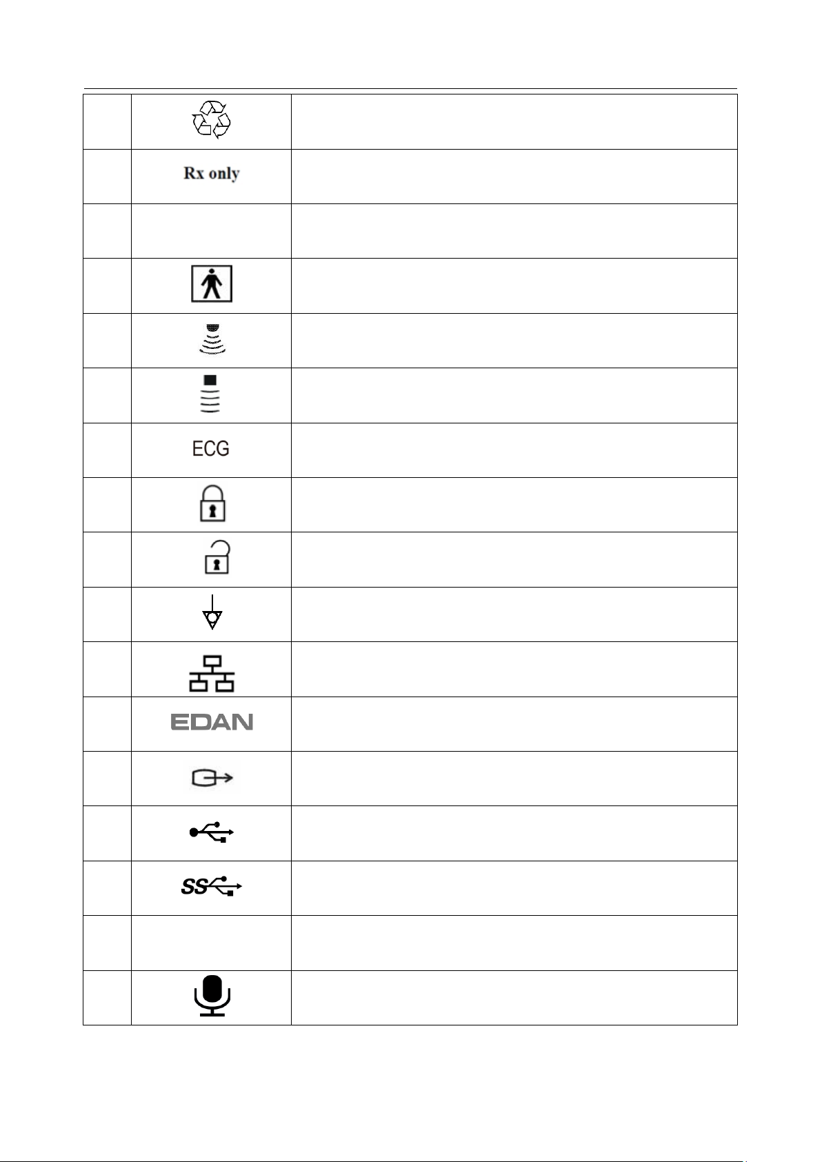
2.3 Labeling Symbols
The following labels are used on the system:
- 7 -
Acclarix LX9 Series Diagnostic Ultrasound System User Manual Safety
13
General Symbol for Recovery / Recyclable
14
Caution: Federal (U.S.) law restricts this device to sale by or on the
order of a physician.
15
IPX7
No harm for short time immersion
16
Type BF Applied Part
17
Transducer connector
18
Pencil Transducer connector (reserved)
19
ECG connector
21
Transducer lock
22
Transducer unlock
23
Equipotential grounding
24
Network port
25
Trademark
26
Video Output port
27
USB 2.0 port
28
USB 3.0 port
29
HDMI
HDMI port
30
Microphone input
- 8 -
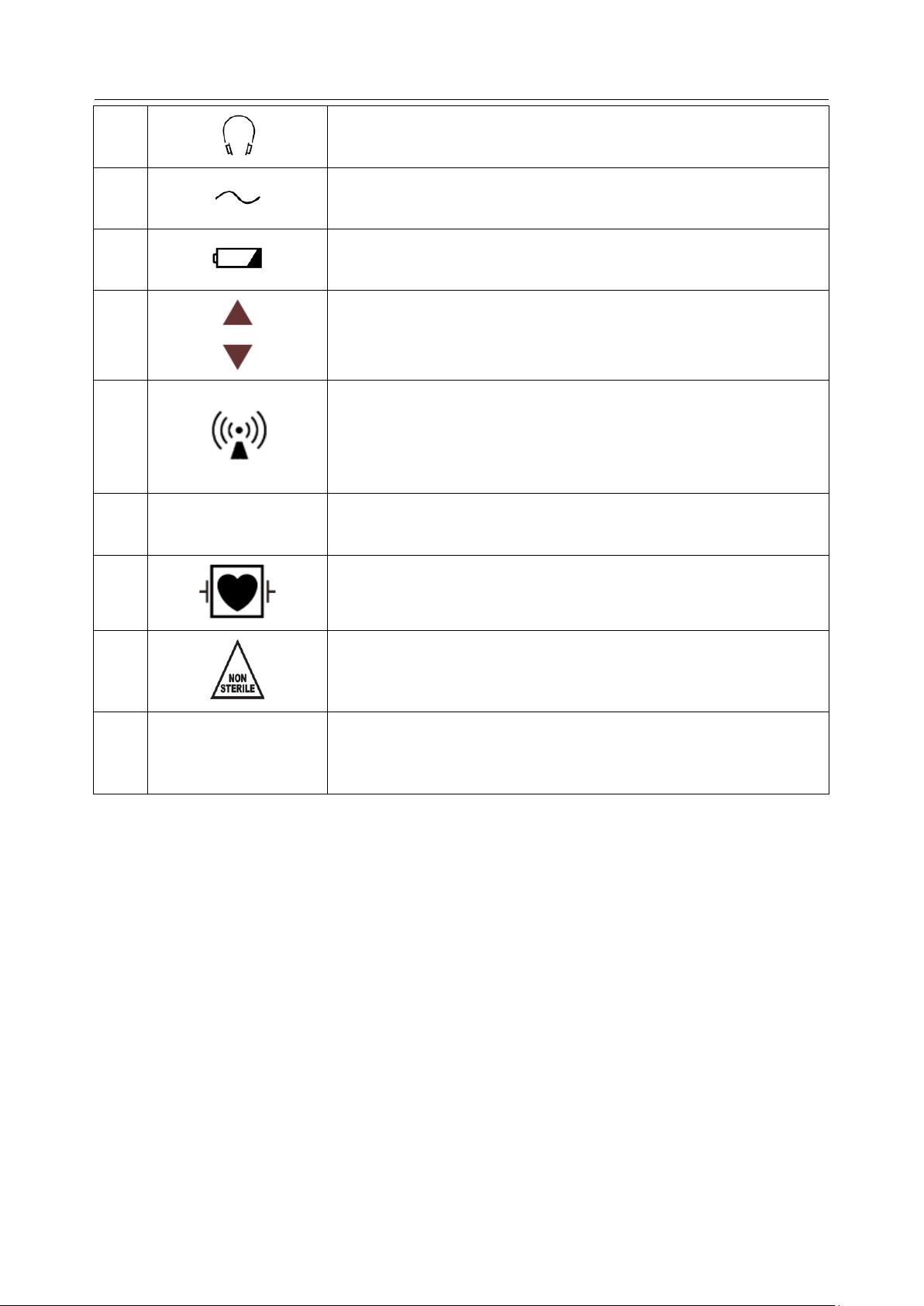
Acclarix LX9 Series Diagnostic Ultrasound System User Manual Safety
31
Audio output
32
AC power indicator
33
Batter charging indicator
34
Up/Down button, to move the control panel up or down
35
Non-ionizing electromagnetic radiation.
36
FCC
ID:SMQLX9EDAN
Federal Communications Commission:
FCC ID:SMQLX9EDAN
37
Type CF Applied Part with Defibrillation-proof protection
38
Non-sterile. Indicates a medical that has not been subjected to a
sterilization process.
39
IP68
Dust-tight (No ingress of dust); No harm for continuous immersion
in water
- 9 -
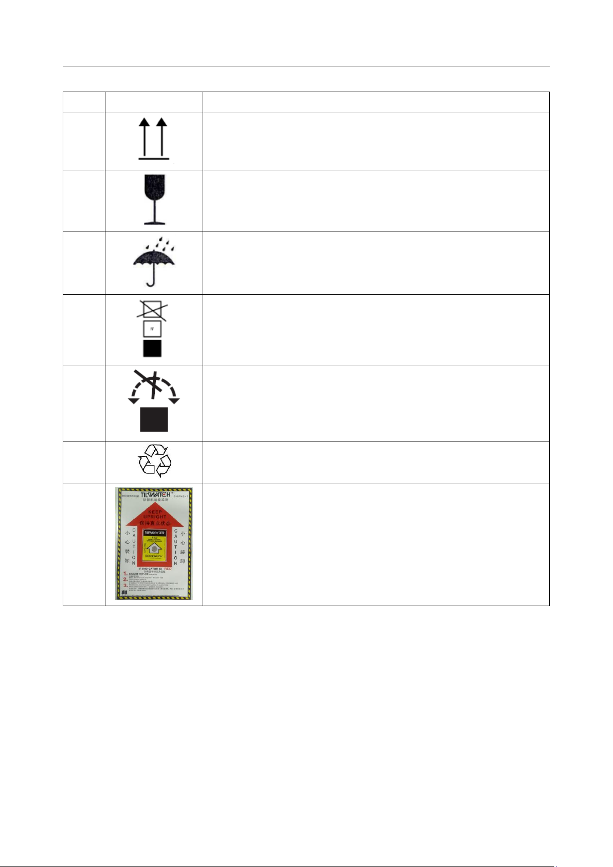
Acclarix LX9 Series Diagnostic Ultrasound System User Manual Safety
No.
Symbol
Definition
1
This way up
2
Fragile, handle with care
3
Keep dry
4
Stacking limit by number
5
Do Not Roll.
6
General Symbol for Recovery / Recyclable
7
Tilt monitored equipment.
The following labels are used on the wooden packaging:
NOTE:
The user manual is printed in black and white.
- 10 -

Acclarix LX9 Series Diagnostic Ultrasound System User Manual Getting Started
Model
Angle/Depth
Description
BGK-C5-2
20°, 28°, 40°
For use with the C7-2XQ/C5-2Q,
Supports: 14G-23G
BGK-L40UB
34°, 43°, 53°, 66°
For use with the L17-7HQ,
Supports: 14G-23G
BGK-CR10UA
2°
For use with the E8-4Q,
Supports: 16G, 18G
BGK-R15UB
12°, 20°, 35°
For use with the MC8-4Q,
Supports: 14G-23G
BGK-001
1.0cm, 1.5cm, 2.0cm
For use with the L17-7HQ,
Supports: 21G
BGK-004
12°, 20°
For use with the MC9-3TQ,
Supports: 14G-23G
BGK-005
0°
For use with the E10-3BQ,
Supports: 16G, 18G
BGK-006
1°
For use with the E10-3HQ,
Supports: 16G, 18G
BGK-007
18°, 25°, 35°
For use with the C5-1Q,
Supports: 14G-23G
3 Getting Started
3.1 System Configuration
Standard Configuration:
1 main unit
1 power cord
1 potential equalization conductor
1 bottle of coupling gel
1 basic user manual and 1 advanced user manual
Options:
Transducers: L17-7HQ, E8-4Q, C5-2Q, L12-5Q, L17-7SQ, MC8-4Q, P5-1Q, P7-3Q,
MC9-3TQ, C7-2XQ, E10-3BQ, E10-3HQ, C6-2MQ, C5-1Q
Needle Guide Bracket Kit
Footswitch
Ultrasound gel warmer
USB disk
Table 3-1 Needle Guide Bracket Kits
- 11 -

Acclarix LX9 Series Diagnostic Ultrasound System User Manual Getting Started
Printer Type
Printer Model
Interface
Color Video Printer
SONY UP-25MD
S-Video
SONY UP-D25MD
USB
B/W Video Printer
SONY UP-X898MD
USB
Report Printer
HP Officejet Pro 251dw
USB
HP LaserJet Pro 200 color M251n
USB
HP LaserJet CP1525n Color
USB
HP Deskjet Ink Advantage 2010
USB
HP Deskjet 1010
USB
HP Deskjet 1510
USB
HP LaserJet 400 M401d
USB
HP DeskJet Ink Advantage Ultra 2029
USB
HP DeskJet 1112
USB
Canon E518
USB
Canon iP2780
USB
HP LaserJet Pro MFP M126nw
USB
HP DeskJet 1050
USB
HP DeskJet 2050
USB
HP LaserJet M252n
USB
Two batteries
Wifi module
ECG module
Supported Peripheral Accessories:
The recommended printers are listed as follows:
Many other printers may also work with Acclarix systems. To check if your printer works, connect it to
the system, go to Set-up->Store/Print, and click the Add button. Once it is added, confirm correct
operation by clicking the Test button.
If that does not work, you may need to download a printer ppd file from the printer supplier. In that
case download the ppd file to your local computer, and then copy it to a USB stick inside a directory
named “ppd”. Insert that USB stick into the Acclarix system along with the printer and try again. Most,
but not all, printers will work with the Acclarix systems. A list of printers that should be compatible can
be found at https://developers.hp.com/hp-linux-imaging-and-printing/supported_devices/index, or at
http://gimp-print.sourceforge.net/p_Supported_Printers.php.
Table 3-2 Printer List
- 12 -
Acclarix LX9 Series Diagnostic Ultrasound System User Manual Getting Started
2
8
9
6 3 18
10
7
5
1
15
16 4 11
13
14
17
12
19
WARNING
Only the recommended printers listed above are verified by EDAN. Therefore, it is suggested to only
use these printers. Use of other printers should comply with IEC 60950 or IEC 60601-1. Edan is not
responsible for the accuracy of other printers.
Recommended DVD drives: LITEON
3.2 System Overview
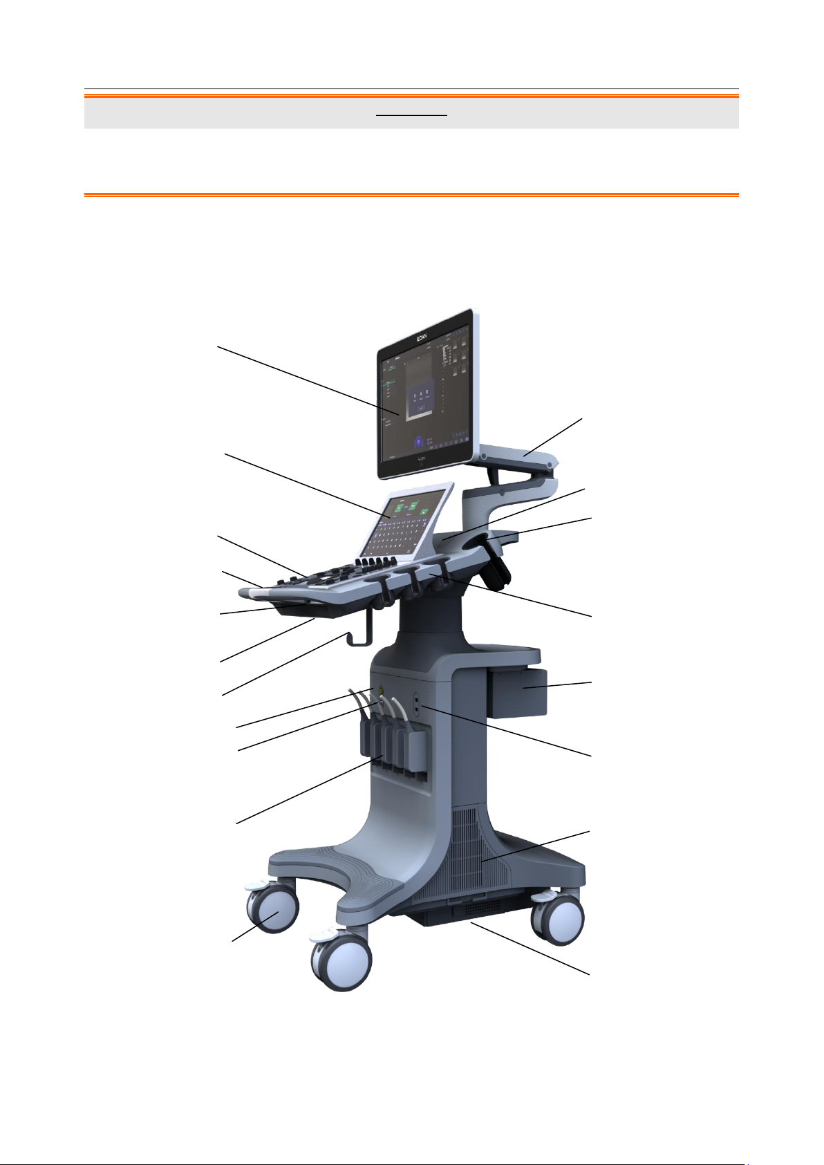
3.2.1. Main Unit
Figure 3-1 Main Unit
- 13 -
Acclarix LX9 Series Diagnostic Ultrasound System User Manual Getting Started
No.
Description
No.
Description
1
Monitor
11
Monitor Support Arm
2
Touch Screen
12
Speaker
3
Control Panel
13
Coupling Gel Holder
4
Handle
14
Transducer Holders
5
Control Panel Height Adjusting
Lever
15
Video Printer /DVD
Drive(optional)
6
Physical Keyboard
16
USB Port(two)
7
Cable Holder
17
System Vents
8
ECG Connector
18
Wheels(four)
9
Pencil Transducer Connector
(Reserved)
19
Battery Compartment
10
Transducer Sockets(five)
Table 3-3 Main Unit Description
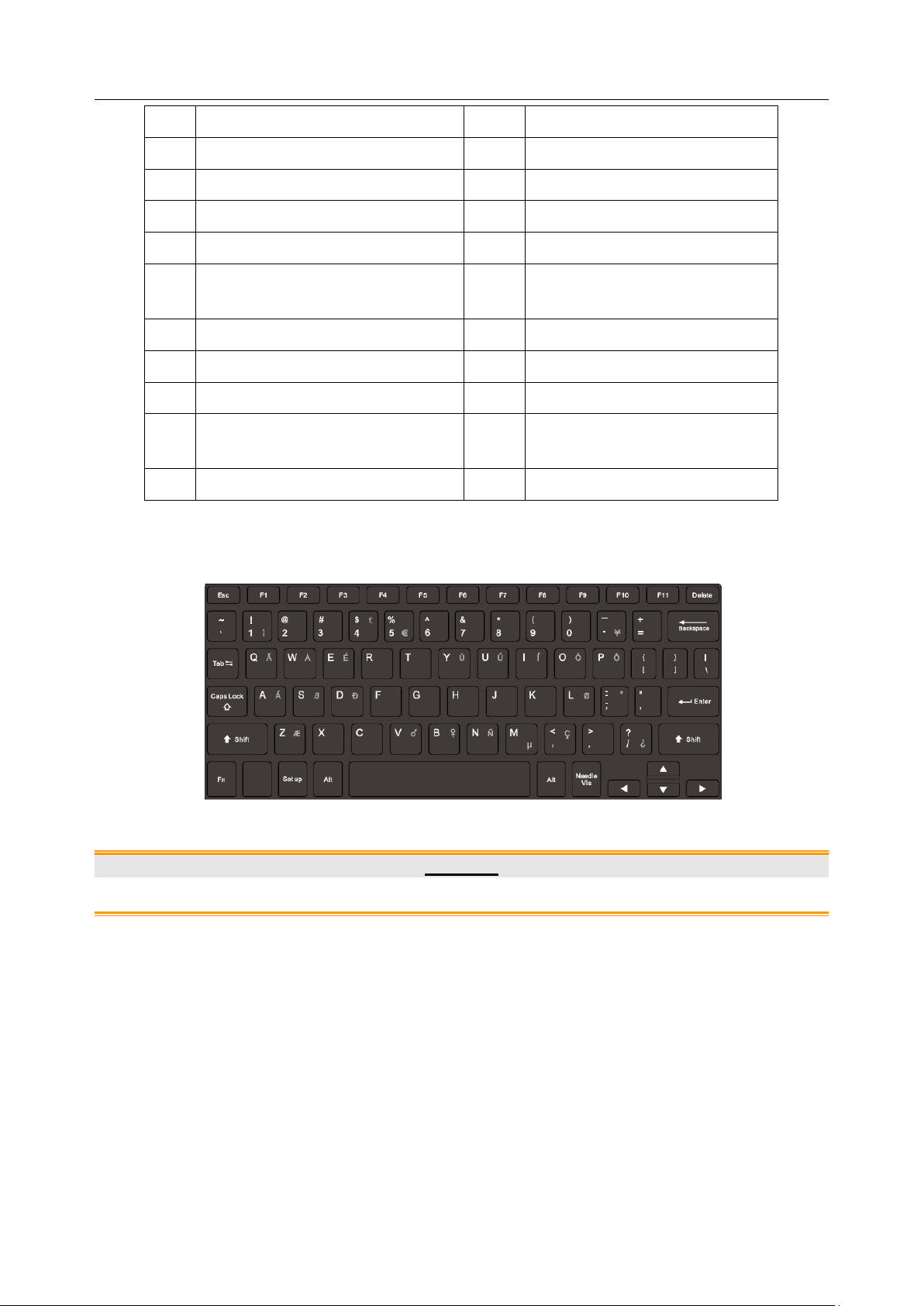
Press down the keyboard case on figure 3-1 to open the keyboard for editing. Push it back after
usage.
Figure 3-2 System Keyboard
CAUTION
1. Ensure system vents are clear and unobstructed.
- 14 -
Acclarix LX9 Series Diagnostic Ultrasound System User Manual Getting Started
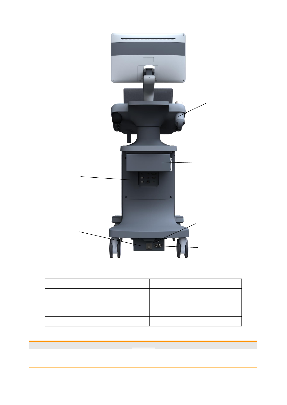
No.
Description
No.
Description
1
Coupling Gel Holder/
Gel Warmer(Optional)
2
I/O Ports
3
Video Printer/DVD Drive(Optional)
4
Air Switch
5
Equipotential Terminal
6
AC Power Socket
4
1
2 3 5
6
1. To facilitate the disconnection from power supply, please do not cover the AC power socket with
any object.
Figure 3-3 Rear View
Table 3-4 Rear View Description
CAUTION
- 15 -
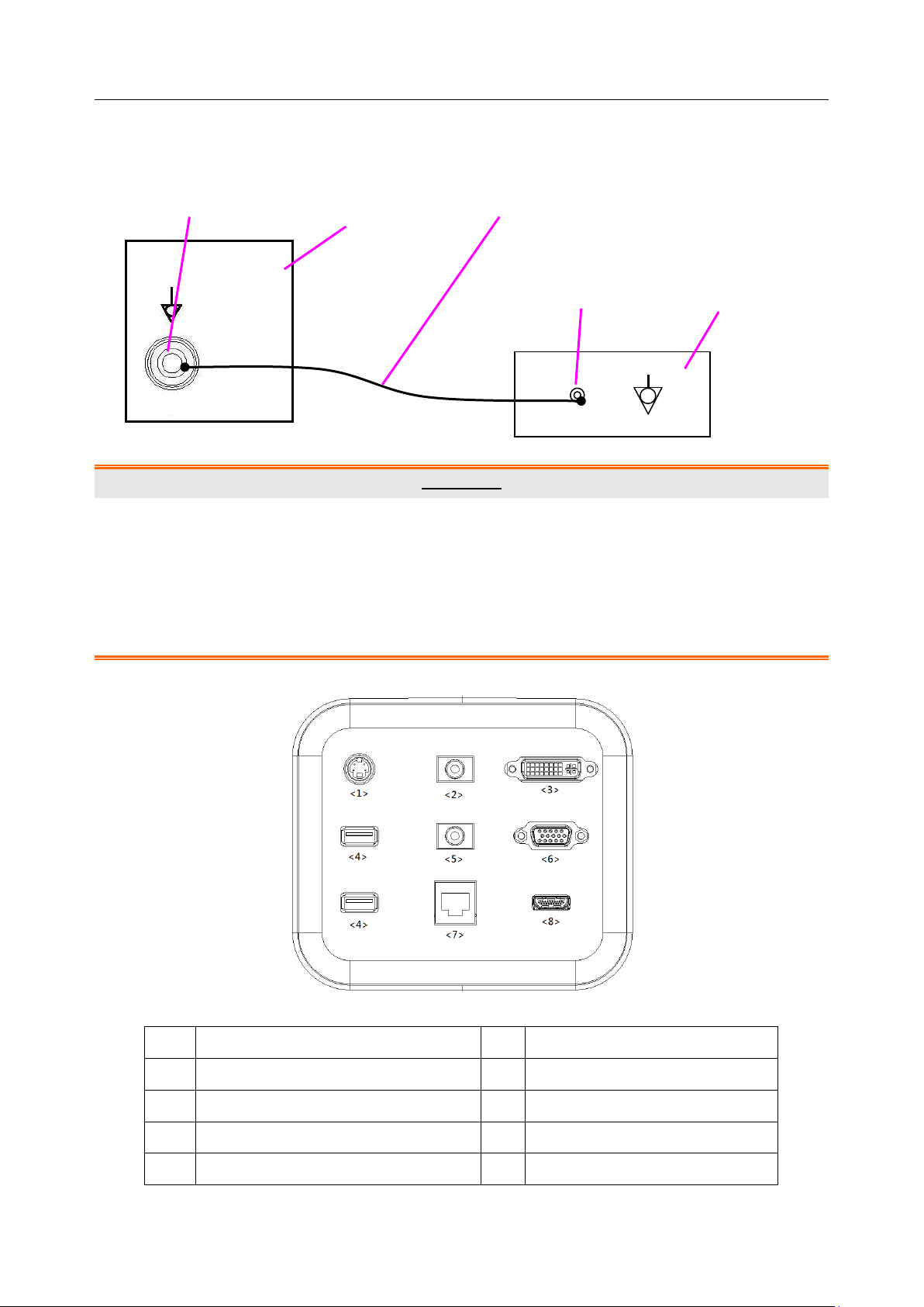
Acclarix LX9 Series Diagnostic Ultrasound System User Manual Getting Started
No.
Description
No.
Description
1
S-Video output port
2
Audio output port
3
DVI port
4
USB port
5
Microphone port
6
VGA port
7
Network Port
8
HDMI port
Equipotential terminal Rear panel Potential equalization conductor
Equipotential Connection
The equipotential terminal is used for balancing the protective earth potentials between the ultrasound
system and other electrical devices. Perform the equipotential connection as the following illustration.
WARNING
1. When you connect another device to the ultrasound system, a potential equalization conductor
should be used to connect each of the equipotential terminals. Otherwise, electric shock may
result.
2. Any device connected to the ultrasound system must meet the requirements of the applicable
IEC/EN60601 series safety standards, and/or the system configuration must meet the
requirements of the IEC/EN60601-1.
I/O Ports on the Rear Panel
Figure 3-5 I/O ports
Table 3-5 I/O ports description
- 16 -
Acclarix LX9 Series Diagnostic Ultrasound System User Manual Getting Started
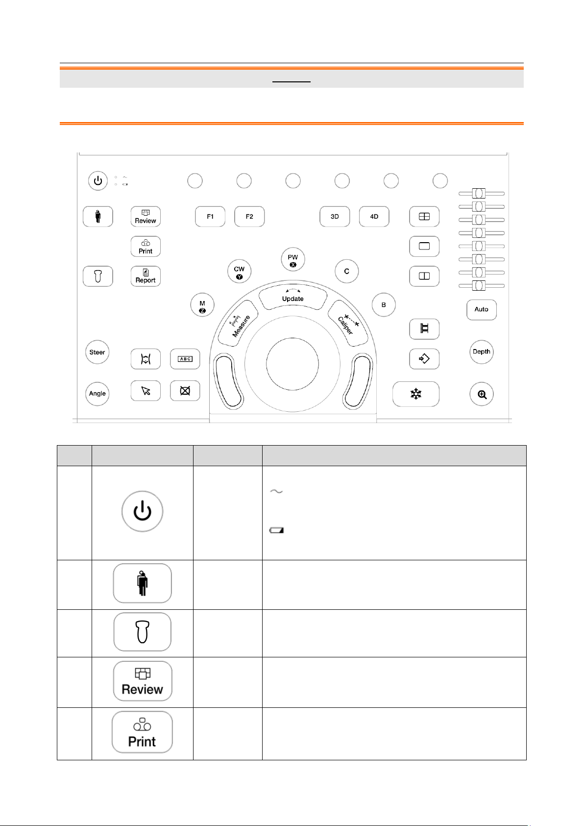
No.
Key
Name
Description
1.
Power Switch
Press to power on/off the system.
: AC power supply indicator. It illuminates in green
when the system is connected to AC power supply.
: Battery charging indicator. It illuminates in green
when the battery is charging.
2.
Patient
Invokes the Patient Information Screen typically used to
start/end exams or to modify patient information during
an exam.
3.
Transducer
Press to switch transducer or exam presets.
4.
Review
Press to enter exam database or image review mode.
See section 9.2 for details.
5.
Print
Press to print images via the connected USB video
printer.
Caution
1. The resolution of the external display which connects to DVI port or HDMI port should be 1080P,
otherwise the display will be abnormal.
3.2.2. Control Panel
Figure 3-6 Control Panel
- 17 -
Acclarix LX9 Series Diagnostic Ultrasound System User Manual Getting Started
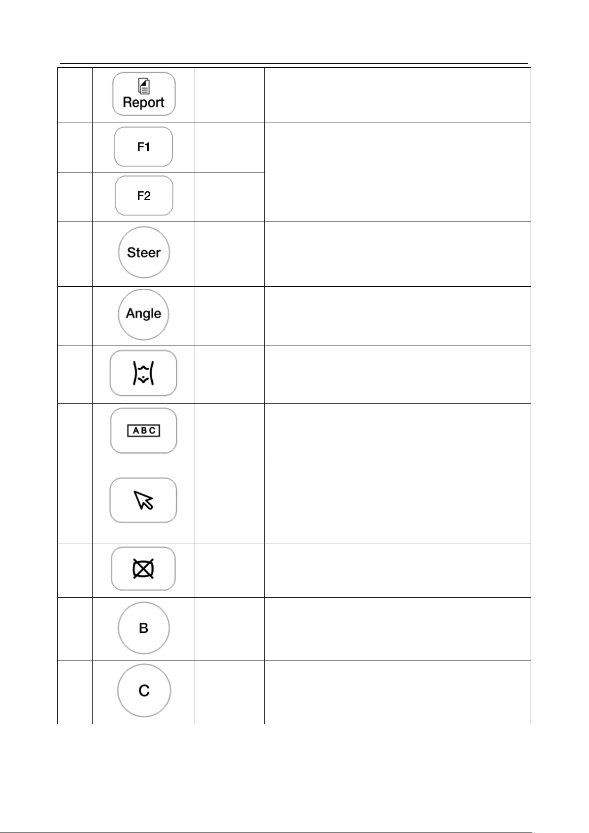
6.
Report
Press to display the report page.
7.
F1
User-defined button. See section 11.1.1 for configuring
the user-defined button.
8.
F2
9.
Steer
The Steer knob control is only available for linear
transducers. It can steer B-mode image, Color ROI, PW
sample line, etc. Specific operations thereof are
described throughout the user manual.
10.
Angle
Adjusts the angle of comment, body marks, needle, M
sample line, etc. Specific operations thereof are
described throughout the user manual.
11.
Body Mark
Enters or exits the Body Mark function.
12.
Comment
Enters or exits the Comment function.
13.
Cursor
Press to hide or display the mouse cursor.
When pressing Cursor while using the Comments
function, the system will display a green cursor in the
image field that can be used to point to anatomical
structures.
14.
Clear
Press to clear all the measurements, calculations,
comments, and body marks displayed on the current
image.
15.
B
Press to return to B-mode imaging from any other
imaging mode and rotate to adjust the gain in B Mode.
16.
Color
Press to enter or exit Color Mode and rotate to adjust the
gain in Color Mode.
- 18 -
Acclarix LX9 Series Diagnostic Ultrasound System User Manual Getting Started
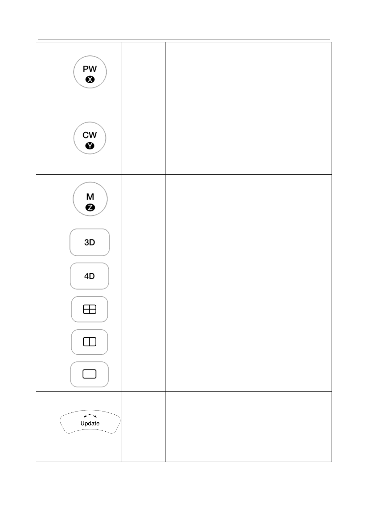
17.
PW
Press to get the sample line. Use the trackball to adjust
the position of the sample line. Press it again or press
<Update> key to display the Doppler strip. Rotate this
knob to adjust the gain in PW Mode.
In 3D/4D mode, rotating it can rotate the image by the
X-axis of the activated window.
18.
CW
Press to get the sample line. Use the trackball to adjust
the position of the sample line. Press it again or press
<Update> key to display the Doppler strip.
This knob is only available when the current active
transducer is a phased transducer .
In 3D/4D mode, rotating it can rotate the image by the
Y-axis of the activated window.
19.
M
Press to enter or exit M Mode and rotate to adjust the
gain in M Mode. Use the trackball to adjust the M sample
line.
In 3D/4D mode, rotating it can rotate the image by the
Z-axis of the activated window.
20.
3D
Press to enter or exit 3D Mode. It is only available when
the current active transducer is a wobble transducer.
21.
4D
Press to enter or exit 4D Mode. It is only available when
the current active transducer is a wobble transducer.
22.
Quad
Enters quad split screen. Each single press on it toggles
between four image windows.
23.
Dual
Enters dual split screen. Each single press on it toggles
between two image windows.
24.
Single
Press to display the currently active side of Dual image
as a single image.
25.
Update
In measurement, pressing <Update> switches the active
side of calipers. See section 8.1 for details.
In Pre-Doppler mode, pressing <Update> invokes
Spectral Doppler mode. When Spectral Doppler strip is
displayed, pressing Update allows switching between
live acquisition of the Doppler strip or the reference
image.
- 19 -
Acclarix LX9 Series Diagnostic Ultrasound System User Manual Getting Started
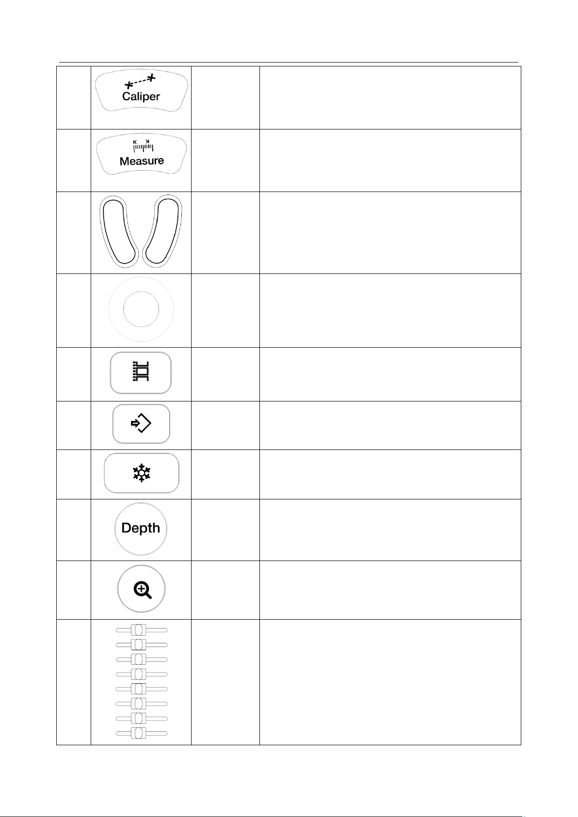
26.
Caliper
Invokes generic measurements. See section 8.1 for
details.
27.
Measure
Invokes application measurements. See section 8.2 for
details.
28.
Trackball
Keys
Two trackball keys provide a wide variety of functions
depending on the system state (e.g., selects a start or
end point of a measurement, selects menu items on the
screen, etc). For the convenience of introduction, we call
them <Set> throughout this user manual.
29.
Trackball
Move the trackball to change the cursor position, adjust
M mark position in M mode, adjust sample line position
in PW mode, etc.
30.
Store Clip
Press to store clips.
31.
Store Image
Press to store static images.
32.
Freeze
Press to switch between the frozen and real-time states.
33.
Depth
Rotate to adjust the depth of the image displayed.
Rotate counterclockwise to decrease the depth and
rotate clockwise to increase.
34.
Zoom
Rotate to use Pan Zoom function, and press to use
Spot Zoom function. See section 7.4 for details.
35.
TGC
The Time Gain Compensation control (TGC) adjusts the
gain of the image at different depths. Each slider can be
adjusted separately.
Glide the slide controls to adjust the TGC. Glide the
upper segments to adjust the near field gain, and the
lower segments to adjust the far field gain; glide
rightward to increase TGC, and glide leftward to
decrease.
- 20 -
Acclarix LX9 Series Diagnostic Ultrasound System User Manual Getting Started
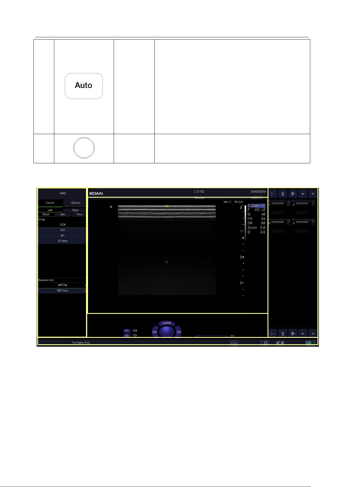
36.
Auto
In B mode, the Auto push button automatically updates
the Overall Gain and TGC.
In PW mode, the Auto push button automatically
updates the PW gain, DR, baseline and scale.
In Color mode, this Auto push button automatically
updates the gain and scale.
Each single press of the button renews the automatic
optimization. Whether Gain, DR or Scale/Baseline is
optimized when pressing Auto button in PW mode can
be configured in Set-up. See section 11.1.4 for detail.
37.
Touch screen
paddle
Knob(Six)
Each of these six knobs adjusts the setting value of one
corresponding paddle control above it on the touch
screen.
①
④
②
③ ⑤ ⑥
Table 3-6 Buttons on Control Panel
3.2.3. Screen Layout
Figure 3-7 Main Screen Display
① Information Field
The top line of this field contains your hospital/institution name. Please see Section
Set-up
The second line of this field contains the patient name, gender, age and ID, as entered through the
Patient Information screen.
This field also contains data fields for:
The currently active transducer
The currently active preset
System date and time.
for information on customization.
11.1.1 General
- 21 -

Acclarix LX9 Series Diagnostic Ultrasound System User Manual Getting Started
No.
Shortcut Keys
Description
1 Select All
Selects all the displayed static images and clips.
2 Delete
Deletes the selected static images and clips.
3 Export
Exports the selected static images and clips to removable
storage devices.
4
Previous/Next
Images
Views previous or next images when more than one page of
images are displayed.
No.
Icons
Description
1
Image Store
icon
Displays the number of static images and clips stored in the
current exam.
2
USB icon
USB available.
3
Printer icon
Printer available.
② Image Field
The ultrasound image appears in the Image field, under the Information field. The Image field also
contains information typically associated with the image, such as depth, TGC, maps, image
parameters, MI and TI.
③ Measurements Display Field
The left side of the screen displays available generic and application measurement items for current
exam preset.
④Thumbnail Field
The right side of the screen displays thumbnail images of all statics and clips captured for currently
active exam or when in Review. This field also contains several shortcut keys for selecting, viewing,
deleting, exporting images. See the below for details:
⑤ User Feedback Field
The user feedback filed is displayed below image field and above status bar. This field displays:
The illustration of trackball and trackball keys.
Cine bar when the system is frozen.
The active function of user custom key F1 and F2.
⑥ Status Bar
The bottom of the screen is used to display icons that provide system status. These include:
- 22 -
Acclarix LX9 Series Diagnostic Ultrasound System User Manual Getting Started
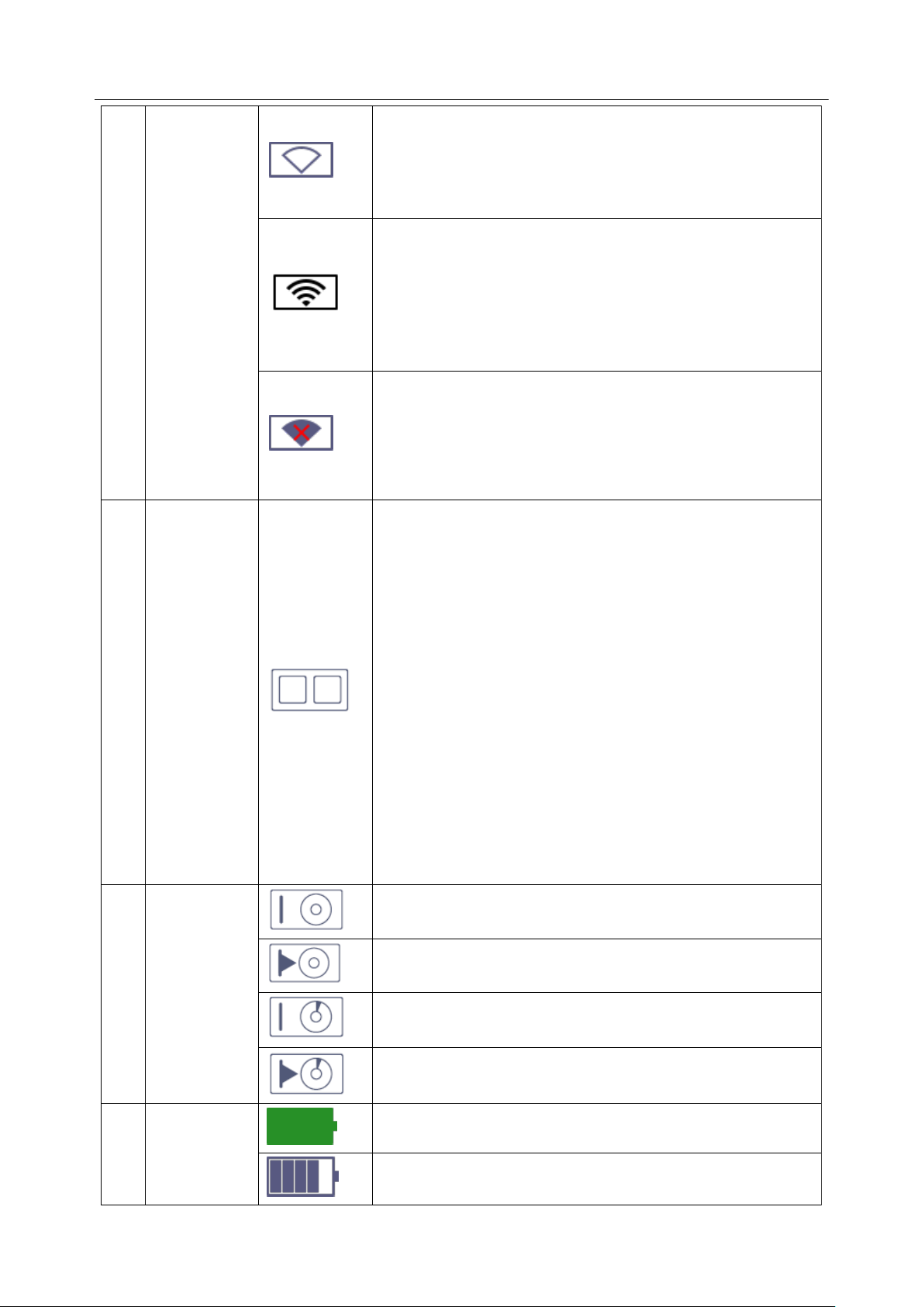
4
Wi-Fi icon
Wi-Fi function is enabled, but no WI-FI network is
connected.
No WI-FI icon will be displayed when Wi-Fi function is
disabled in Connectivity setup.
Wi-Fi network is connected.
Clicking on this icon shows a list of available Wi-Fi networks.
Selecting an available network displays a dialog box for
entering password. Clicking on the "WiFi: Turn off" button
above the list will disconnect the currently connected WI-FI
network.
WI-FI network is disconnected.
Clicking on this icon shows a "WiFi: Turn on" button. Clicking
on this button shows a list of available Wi-Fi networks.
Selecting an available network displays a dialog box for
entering password.
5
Network
status icon
The network status icon shows the connection status of the
Network Server. If no Network Server is defined, then the
icon is not displayed.
Outline in grey color: Successful connection with a
Server.
Outline in green color: Data exchange with a Server.
Outline in red color: Failure to connect with a configured
Server
Clicking on this icon displays a queue of exam or image
transfers and as well as the transfer status of each exam or
image including refuse, pending, active, success and fail.
For a failed transfer, the system will automatically retry the
transfer when the transfer task is available, or user can
manually retry transfer. User can manually delete a transfer
from the queue.
6
Hard Drive
icon
Hard drive available.
Hard drive data exchange, symbol in green.
Hard drive 95% full, symbol in red.
Hard drive 95% full with data exchange, symbol in red.
7
Battery icon
Battery fully charged, symbol in green.
Battery more than 80% charged.
- 23 -

Acclarix LX9 Series Diagnostic Ultrasound System User Manual Getting Started
Battery 60%-80% charged.
Battery 40%-60% charged.
Battery low, symbol in red.
Battery removed, outline in red.
Battery charging.
8
DVD icon
Symbol in grey: DVD device is connected.
Symbol in green: DVD device is connected, disc is inserted
and data transmission is available.
3.2.1. Touch Screen
The Touch Screen contains controls that vary depending on the active imaging mode or function.
There are several types of controls used by the touch screen, as illustrated below:
Figure 3-8 Touch screen of the System
A. Tabs: Each imaging mode that is active has a tab at the top of the touch screen. Usually, the
imaging mode that was most recently activated is the top tab and has priority. Pressing on any
other tab will bring it to the top and provide access to the controls available for that imaging
mode.
B. Paddle: Pressing on the top or bottom of a paddle changes the control setting by one value.
Pressing anywhere on the control and swiping across it will continuously change the value.
Each touch screen page displays at most six paddles. Below each paddle there is a knob on
the console used to change its setting. Pressing and dragging one paddle to the position of
another paddle will switch the position of these two paddles.
C. Push Button: This can either be an on/off control (like “Colorize”) or a one-shot control that
- 24 -

Acclarix LX9 Series Diagnostic Ultrasound System User Manual Getting Started
No
Name
Description
1 Press to enter Color-TDI mode.
2 Press to enter TDI mode.
3 Press to activate ECG function.
4 Press to enter Elastography mode.
5 Press to enter Contrast Imaging mode.
6
Press to open Utilities touch screen, where system setup,
connectivity, presets, screen adjust, system maintenance can
be accessed.
immediately performs an action (like “Auto”)
D. Radio Buttons: A collection of buttons where only one is active at any time. Activating one will
de-activate all others.
E. Folder: Controls can be grouped together into a folder. Press on the folder to open it and
access any of the controls within it.
F. Pages: When a tab has multiple pages of controls each page is represented by a dot at the top
of the page. The current page is indicated by a filled-in dot. You can move between pages by
dragging your finger horizontally across the dots. These dots do not appear when there is only
one page in the current tab.
G. Function Shortcut Key: The left side of the touch screen displays six shortcut keys for
accessing different imaging modes or functions. See the following table for details:
The function of shortcut key 1 to 5 can be configured on System Setup page. See section 11.1.1 for
details.
Customizing the touch screen
The touch screen can be customized to meet your needs. Press and hold any control for about a
second to put the touch screen in customization mode. Continue pressing and drag the control to a
new location.
Creating Folders: Dragging one control on top of another control will create a folder that
contains both controls. Dragging controls out of a folder until only one exists will automatically
delete that folder. Folders cannot contain other folders.
Multiple pages: Dragging a control to the side of the screen will move that control to the next
page.
Radio Button Cluster: There is no restriction on moving a single radio button. However, we
suggest that they are grouped adjacent to each other. When they are grouped in this way the
system will automatically draw a border around them to indicate they are a related group of
radio buttons.
- 25 -

Acclarix LX9 Series Diagnostic Ultrasound System User Manual Getting Started
3.2.4. Trackball
The trackball operation is easy and convenient. It can achieve the following functions:
Move the measurement cursor during measurement.
Move the comment cursor in the comment status.
Move the M Mark in the B+M mode.
Move the scan area of Color mode, increase or decrease the size of scan area of Color mode.
Move the sample line in the PW/CW mode.
Realize single frame playback in the frame-by-frame playback status.
Move the zoomed window in the zoom status.
NOTE:
1. Please be gentle when running the trackball.
2. Please keep the surface of trackball clean.
- 26 -

Acclarix LX9 Series Diagnostic Ultrasound System User Manual Getting Started
3.3 System Preparation
3.3.1. Battery Use
The system may come with two lithium-ion batteries depending on your order. The fully charged
batteries together can run the system for approximately 1.5 hours, depending on use. The batteries
are automatically charged when the system is plugged in.
CAUTION
1. If the system will remain unused for more than one week, charge the battery to at least 75%
capacity, take the battery out and store the system and battery separately.
2. During long term storage, the battery should be charged at least once every 6 months to ensure
battery capacity is more than 75%.
3. Only use Edan supplied battery.
4. Two batteries should be used together to power the system on.
To install the battery:
1. Find the battery compartment, located at the lower right side of the system(see figure 3-1) .
2. Unscrew the two screws on the battery door, and open the battery compartment.
3. Move the battery holder (see the figure below) up or down, and put two batteries inside
respectively. The side with labeling should face down when putting the battery in.
- 27 -

Acclarix LX9 Series Diagnostic Ultrasound System User Manual Getting Started
4. To fix the battery, move the battery holder to the middle position (see the figure below).
5. Close the battery door and secure it.
WARNING
1. When the battery capacity is ≤20%, the battery status icon turns red.
2. When the battery capacity is ≤10%, the system displays a prompt “Low Battery. Please plug in
the adapter to ensure uninterrupted use."
To remove the battery:
1. Find the battery compartment, located at the lower right side of the system(see figure 3-1) .
2. Unscrew the two screws on the battery door, and open the battery compartment.
3. Move the battery holder (see the figure below) up or down, and remove two batteries respectively.
- 28 -

Acclarix LX9 Series Diagnostic Ultrasound System User Manual Getting Started
4. Close the battery door and secure it.
3.3.2. AC Power Use
When using AC power, position the system so that it is easy to disconnect it from AC power supply.
To connect AC power:
1. Connect the AC power cord to the power socket on the system(see figure 3-3).
2. Connect the AC power cord to a hospital-grade power outlet.
3. Toggle the Air Switch beside the power socket to "ON" position.
4. Press the Power button on the control panel to start the system.
WARNING
1. Make sure the AC power supply complies with the following specifications: 100V-240V~,
50Hz/60Hz.
2. Only use a hospital grade, grounded, power outlet and plug. Do not use with an ungrounded
outlet.
3. Only use Edan supplied power cord.
3.3.3. Transducer Connection
To connect a transducer:
1. Align the connector with the transducer port and carefully push into place.
2. Toggle the locking handle to the right position.
3. Do not allow the transducer head to hang free. Impact to the transducer head could result in
irreparable damage.
To disconnect a transducer:
1. Toggle the locking handle to the left position to unlock the transducer connector.
2. Firmly grasp the transducer connector and carefully remove it from the system port.
3. Store transducer in its protective carrying case prior to transport.
CAUTION
1. Do not touch the pin of transducer connector.
2. Broken or bent pin will affect the image quality. Please do not the transducer with broken or bent
pin.
3. Do not plug in or pull out the connector when the device is activated. This is to avoid
uncontrollable damage to the transducer and the main unit.
- 29 -

Acclarix LX9 Series Diagnostic Ultrasound System User Manual Getting Started
4. Ensure the transducer is connected firmly and properly. This is to avoid bad contact between the
transducer and transducer socket.
5. Ensure that the system is shut down, or the image is frozen, before connecting and disconnecting
transducers.
3.3.4. Powering on/ off
Please review and follow the steps described in the Section
the system.
To power on
1. Connect the AC power supply.
Or, use the battery as the power supply.
2. Press the Power on/off key on the top left of control panel.
To Login
If Password Protection is enabled (see section 11.1.5), the system displays a Login dialog when
booting up the system. Type in or select user name from the User Name drop-down list, then
enter password and click Login.
For emergency use, click on Emergency to log on directly without entering user name and
password.
13.1.Daily Checklist
prior to powering on
NOTE:
1. When both Admin1 and Admin2 password are forgotten, please contact the serviceman for
the system password reset.
2. It is not suggested to use Emergency login under non-Emergency situation. Please login the
system with your account or switch to your account through the Switch User function (See
"To Switch Users" below) prior to imaging scanning.
3. Ensure the privacy of patient information and data created through Emergency login. It is
suggested to remove the patient exam data from the ultrasound system after Emergency
scanning for protecting patient data from being accessed by unauthorized users.
To Switch Users
If Password Protection is enabled, switching users is allowed without restarting the system.
1. Press Power on/off key, and the system will display a confirmation dialog box.
- 30 -

Acclarix LX9 Series Diagnostic Ultrasound System User Manual Getting Started
2. Select User from the confirmation dialog box. A login information dialog box will be displayed
providing access to change user.
3. Select Change User and this brings up the system login dialog box.
4. Select another user from the User Name drop-down list and then enter password to login.
To power off
1. Press the Power on/off key on the top left of control panel and the system displays a
confirmation dialog box.
2. Select “Shut Down” from the confirmation dialog box.
If the system is unresponsive, a long press of the Power on/off key will shut down the system
directly.
NOTE:
1. Turn off and unplug the device after use.
2. Please unplug the power cable from the power socket and disconnect the battery prior to
storage.
Sleep mode
The system will enter a sleep mode that maintains exam information while using minimal power.
There are two events that can invoke sleep mode:
No user input for a configurable amount of time. Please see System Set-up to configure
this time.
Pressing the Sleep button on the confirmation dialog box when powering off.
Figure 3-9 Confirmation dialog box when power off(Password protection is enabled)
Pressing any key on the control panel or moving the trackball will exit the sleep mode.
3.4 Monitor Position Adjustment
Before adjusting the position of the monitor, you need to unlock the upper support arm. To unlock the
upper support arm, press the release button(see the figure below).
- 31 -

Acclarix LX9 Series Diagnostic Ultrasound System User Manual Exam Operation
4 Exam Operation
4.1 How to Start an Exam
1. Press the <Patient> key and enter in patient information, or select a scheduled patient from the
modality worklist.
If there is no previous exam, pressing the<Patient> key will bring you directly to the Patient
Information Page (see figure 4-2 below).
If a previous exam is still active you will see the following dialog:
Figure 4-1 Exam Information Page
The following options are available:
End Exam: select this to end the current exam and return to live imaging to start a new
exam.
Edit Current: This lets you edit the Patient Information for the current exam. It does not
start a new exam.
New Exam: Select this to start a new exam.
If Same Patient is checked, selecting New Exam will end the previous exam and create a
new exam for the same patient. The main screen will display the Patient Information Page
with the previously entered patient information except for the exam accession number. .
Changing the patient information for one exam will not impact the others.
If Same Patient is unchecked, selecting New Exam, a blank Patient Information Page will
be displayed for entering patient information for a new patient.
Tick the check box of Same Patient when operating multiple exams for the same patient.
Cancel: Exits the dialog without starting or ending an exam.
2. Press Start Exam key to start scanning.
3. To change transducer or exam preset, press the <Transducer> key, and then the Transducer
touch screen provides you choices of available transducers and exam presets, as the figure
below.
- 36 -

Acclarix LX9 Series Diagnostic Ultrasound System User Manual Exam Operation
Figure 4-2 Example of Transducer Touch Screen
4.2 How to End an Exam
There are two ways to end an exam:
Pressing the <Patient> key, as described above, and then selecting the New Exam. This both
ends the exam and displays the Patient Information Page for the next exam.
Pressing the <Patient> key, as described above, and then selecting the End Exam. This
brings up a dialog to confirm you want to end the exam, but does not invoke the Patient
Information Page for the next exam.
When an exam is ended, the associated files on the system are closed. If a DICOM server is
connected successfully and Auto-transfer when End Exam is configured, any remaining images are
transferred.
4.3 How to Restart an Exam
1. Select an exam from the Exam Database within the time limit selected in Patient Set-up menu.
For the setting of time limit, refer to section
9.1.2 Patient Set-up
.
2. Press Restart key to continue/edit the exam that was performed on the selected patient. You
can also modify the patient information by pressing <Patient>-->Edit Current.
4.4 The Patient Information Page
The Patient Information Page is used to enter or modify patient demographic data. The following
figure is an example:
- 37 -

Acclarix LX9 Series Diagnostic Ultrasound System User Manual Exam Operation
Figure 4-2 Patient Information Page
The top three lines are for entering the patient last name, first name, ID, exam accession number, and
DOB (Date-of-Birth) or age. If date of birth is entered, the age is automatically calculated.
Note:
By default, the patient name has two fields: family name and given name. It can be configured to be
one field in the Patient Setup screen (See section 11.1.2 for detail).
The next line shows the current transducer and the preset that will be used for the current exam. The
preset can be changed by clicking the drop-down menu and selecting another preset associated with
the current transducer.
The lines below the preset selection vary depending on the current preset and display fields that are
preset-specific. All the possible patient information fields you may need to fill in are listed below:
Gender: Select the patient‟s gender: “M” (Male), “F” (Female), “O” (Other), or “<blank>”. “F” is
default for gynecology, obstetric and breast exams; “M” is default for prostate exam and testis
exam; <blank> is default for all other exam types.
LMP: Last Menstrual Period (yyyy/mm/dd or mm/dd/yyyy), If LMP is entered then GA and EDD
are calculated. Entering EDD does not impact LMP. An LMP more than 300 days ago is
considered invalid.
GA: Gestational Age (xxWyD), it is auto-calculated when LMP or EDD is entered (only in OB
Exam).
EDD: Estimated Date of Delivery (yyyy/mm/dd or mm/dd/yyyy), if EDD is entered then GA is
- 38 -

Acclarix LX9 Series Diagnostic Ultrasound System User Manual Exam Operation
calculated. An A GA more than 42W6D days is considered invalid.
Fetus: Enter 1 up to 4 for multiple gestations.
G/P/A: G stands for Gravida, P stands for Para and A stands for Aborta. Enter values for each
in the fields separated by slashes.
Study Description: enter the study description.
Height: Enter the patient‟s height. The units can be set in the Patient section of Setup.
Weight: Enter the patient‟s weight. The units can be set in the Patient section of Setup.
BSA: Body Surface Area, it is auto-calculated and displayed when Height/Weight is entered.
HR: Enter the Heart Rate.
BP: Enter the Blood Pressure.
PSA: Prostate Specific Antigen.
PPSA Coefficient: Predicted Prostate Specific Antigen.
Ref. Physician: Enter the name of the Ref.Physician.
Dx. Physician: Enter the name of the Dx.Physician.
Operator: Enter the name of the person performing the exam.
CPT code: Current Procedural Terminology code.
<Custom field 1>: Enter the user-defined data.
<Custom field 2>: Enter the user-defined data.
Comments: Enter any additional comments.
While the Patient Information Page is displayed the following buttons are displayed on the touch
screen and Patient Information Page:
Press Start Exam to exit the Patient Page function and return to B-mode imaging with the
newly entered demographic data for the active exam.
Press Cancel to exit the Patient Information Page without storing any of the entered data.
Press Clear All to clear all of the demographic fields except for name and ID.
Input LMP, and press Prior Exam to enable the entry of previous OB exam data for fetal
trending details. This option is only available when an OB preset is selected.
4.5 Modality Worklist
Modality worklist provides a list of scheduled patients derived from a DICOM server. It is available only
when a DICOM server is configured and worklist is enabled.
When the modality worklist function is enabled and configured in DICOM Connectivity screen, the
worklist is shown to the left of the Patient Information Page, as shown below.
- 39 -

Acclarix LX9 Series Diagnostic Ultrasound System User Manual Exam Operation
Figure 4-4 Modality Worklist Display
The worklist is displayed at the left side of the Patient Information Page in two columns labeled patient
name and patient ID. Clicking on the header of each column will sort the list for the corresponding
column.
The worklist shows all scheduled ultrasound exams within the date-range specified in the Connectivity
Utility (See 11.2.2). Typing any text in the Patient Name or ID fields will filter the list to exams that
contain the entered text.
Update: Press to query the patient data and update the list manually.
Hide List: Press to hide the list with only a Show List button displayed. Press the Show List button to
display the list and other buttons.
Select one patient from the list and the detailed patient information is entered into the associated fields
on the patient information page, with the option to edit or complete. Then press Start Exam on the
touch screen to start an exam.
- 40 -

Acclarix LX9 Series Diagnostic Ultrasound System User Manual Imaging
Name
Control
Description
Dynamic
Range
The Dynamic Range, or log compression, adjusts how echo
intensities are converted to brightness. A high dynamic range
will display more shades of gray, while a low dynamic range will
display fewer shades of gray and a more contrasty image.
LGC
Lateral Gain Control (LGC) adjusts the gain along the scan line
to improve the lateral resolution of the image. Press LGC touch
screen key to display 8 gain control sliders. Move the slider
downwards to decrease the gain, while move the slider upwards
to increase the gain.
eSRI
eSRI is Speckle Reduction Imaging. High level provides more
aggressive speckle reduction.
Persistence
Persistence averages frames together to reduce random noise.
There are 4 options: Off, Low, Med., and High. The persistence
level corresponds to the number of frames averaged. The frame
rate is unchanged.
Frequency
Frequency allows selection of the fundamental or harmonic)
frequencies used for imaging. The Harmonic option must be
invoked to access the harmonic frequencies. Frequency
selection is available during live imaging.
Harmonic
The Harmonic control invokes and exits harmonic imaging.
While in harmonic imaging the control is highlighted and an „H‟
is displayed in the B-mode frequency field. Depending on the
transducer there may be multiple harmonic frequencies.
5 Imaging
5.1 B-mode
5.1.1. Using B-mode
1. Press <B> on the console to enter B mode.
2. Perform the image scanning.
3. Adjust Image parameters to optimize the image.
5.1.2. B-mode Image Optimization
The following touch controls can be used to optimize the B-mode image.
- 41 -

Acclarix LX9 Series Diagnostic Ultrasound System User Manual Imaging
Spatial
Compounding
Spatial Compounding combines images fired from multiple
angles to reduce speckle, reduce shadow artifacts, and
enhance contrast. Spatial compounding is an on/off control.
Focus Number
Focus Number adjusts the number of foci is displayed. As the
number of foci increases, image uniformity across depth will
increase, but the frame rate will decrease.
Focus Position
Focus Position adjusts the depth of the focus or foci. Upward
presses move the focus shallower, regardless of the U/D invert
status of the image.
Gray Map
Gray Map adjusts the post processing map used on the B-mode
image. In general, higher map numbers correspond to more
contrast in the image.
Colorize
The Colorize control adds a color tint to the B-mode image.
Tint
The Tint control changes the color tint being used. If Colorize
had been off, changing the Color map control will automatically
activate it.
Left/Right
The Left/Right invert control is indicated by a backward R and is
used to toggle the left/right orientation of the image. The Edan E
orientation marker at the top of the image switches with the
left/right invert to match the orientation marker on the
transducer.
Up/Down
The Up/Down invert control is indicated by an upside-down R
and is used to toggle the up/down orientation of the image. The
TGC curve is also re-oriented with Invert On, so that the top of
the TGC curve corresponds to the top of the image on the
screen.
FOV
The Field of View control adjusts the image width. Full, Large,
Med. and Small settings are available. As the image becomes
narrower, the frame rate increases.
- 42 -

Acclarix LX9 Series Diagnostic Ultrasound System User Manual Imaging
Steer
The Steer control is only available for linear transducers and
steers the B-mode image left or right, without moving the
transducer. This function can be particularly useful when
visualizing needles or other objects that are enhanced by a
perpendicular beam. Steer is not available if Spatial
Compounding, Extended FOV or Panorama is turned on.
Panorama
The Panorama control invokes the Panorama function. See
section
5.10
for details.
Image Type
B-mode supports presets for Detail, General, and Penetration.
Line Density
Adjusts the line density to optimize the lateral resolution for the
best possible image. The higher the line density, the higher the
lateral resolution, but the lower the frame rate.
Single
Press to display the currently active side of Dual image as a
single image.
Dual
Press to activate dual imaging mode. See section
7.3.1 Dual
Imaging
for details.
Quad
Press to activate quad imaging mode. Refer to section
7.3.2
Quad Imaging
for details.
3D/4D
Press to activate 3D/4D imaging mode. Refer to section
5.9
3D/4D mode
for details.
Acoustic power
Adjusts the acoustic output power of the activate transducer. It
is only available in live imaging. Higher acoustic power numbers
correspond to increased sensitivity in the image with improved
penetration, but the ALARA principle should be followed in
actual clinical situations.
- 43 -

Acclarix LX9 Series Diagnostic Ultrasound System User Manual Imaging
Needle
Press to invoke the touch screen for Needle Enhancement
Visualization and Needle Biopsy Guide functions. See section
6.4 and 6.5 for more information.
Center Line
Press to activate the Center Line function. Refer to section 6.6
for details.
Extended FOV
Press to invoke extended field of view function. Only available
for linear transducers.
The extended field of view function displays as trapezoid
imaging, and its imaging width is adjustable with three levels.
Off is to disable the extended field of view function.
Elastography
Press to invoke Elastography mode. Refer to section 5.11 for
details.
Contrast
Press to invoke Contrast Imaging mode. Refer to section 5.12
for details.
Table 5-1 B-mode Touch Screen Controls
- 44 -

Acclarix LX9 Series Diagnostic Ultrasound System User Manual Imaging
Name
Control
Description
Color
Mode
Variation
A set of radio-buttons display the color modes that are available on
the current transducer, and let you switch between them. See
section 5.2.1 for details.
Scale
Scale adjusts the range of velocities that are displayed. Upward
presses increase scale and downward presses decrease it. It is
available in Velocity, PDI, and DPDI. It is not available in
Freeze/Cine.
5.2 Color Mode
5.2.1. Color Mode Variants
The system supports 3 types of Color Doppler imaging:
Color (Color Doppler): This is velocity Color Doppler that shows direction and velocity of flow.
Different colors represent different velocities and positive flow has different colors than
negative flow.
PDI (Power Doppler Imaging): PDI shows the power, or intensity, of the Doppler signal. PDI is
typically more sensitive to low levels of flow, but cannot distinguish the velocity or direction of
the flow.
DPDI (Directional Power Doppler Imaging): This is similar to DPI in that it shows the power of
the Doppler signal instead of the velocity. However, it does map positive flow to different colors
than negative flow.
5.2.2. Using Color Mode
1. Perform the image scanning to get a good image in B mode;
2. Press <C> to enter B+Color mode and display ROI box;
3. Adjust the size and position of ROI box.
Presses on <Set> switch between the status of adjusting the size and position of ROI box. Use
trackball to adjust.
4. Press PDI, DPDI or Color mode key on the touch screen to switch Color Doppler modes when
necessary;
5. Adjust image parameters to optimize the Color image.
5.2.3. Color Image Optimization
The following touch controls can be used to optimize the Color image.
- 45 -

Acclarix LX9 Series Diagnostic Ultrasound System User Manual Imaging
Invert
Normally, signals above the baseline are positive velocities (moving
toward the transducer). However, when Invert is pressed then
negative velocities are above the baseline. Invert does not affect the
baseline position. Invert is not available in PDI mode.
Baseline
The Baseline control adjusts the Color baseline. Upward presses
move the baseline up on the scale and downward presses move the
baseline down. Baseline is not available in PDI mode.
Wall Filter
The Filter control removes excessive noise from movement of
vessel walls. Options of Low, Med and High are available.
Map
Adjusts the current map for the active color variation.
Persist
Persistence determines the number of frames that are averaged
together for display. Levels of Off, Low, Med and High are available.
Smooth
Filter
The smoothness filter determines the spatial filtering that is applied
to the Color image. Higher filter levels create a smoother image.
Upward presses increase the filter. Downward presses decrease the
filter.
Threshold
When the system receives both B-mode and color signals from a
region within the Color ROI box, the Threshold determines whether
to display overlapping signals as grayscale or color.
In Color mode, higher Threshold values display more color, and
lower Threshold values display more grayscale.
In TDI mode, higher Threshold values display more grayscale, and
lower Threshold values display more color
Upward presses increase threshold. Downward presses decrease
threshold.
- 46 -

Acclarix LX9 Series Diagnostic Ultrasound System User Manual Imaging
Frequency
Frequency determines the transmit frequency used by color Doppler.
Upward presses increase the frequency. Downward presses
decrease the frequency.
Steer
This control is only available for linear transducers. It steers the
Color ROI box angle left or right.
Image
Type
Color Doppler supports image presets for Low Flow, Medium Flow,
and High Flow.
Dual Live
To activate split screen with simultaneous live B/Color and live B.
The live B image without color and the same live B image with color
are simultaneously displayed on each side of the image field.
Freezing the image will freeze both sides simultaneously.
Cine review will review both sides simultaneously.
Dynamic
Range
The Dynamic Range, or log compression, adjusts how echo
intensities are converted to brightness. A high dynamic range
presents a flatter, less contrasty color display, while a low dynamic
range presents a more contrasty color display. Only available in
PDI/DPDI mode.
Line
Density
Adjusts the line density to optimize the lateral resolution for the best
possible image. The higher the line density, the higher the lateral
resolution, but the lower the frame rate.
Acoustic
power
Adjusts the acoustic output power of the activated transducer. It is
only available in live imaging. Higher acoustic power numbers
correspond to increased color sensitivity and penetration, but the
ALARA principle should be followed in actual clinical situations.
Table 5-2 Color Mode Touch Screen Controls
- 47 -

Acclarix LX9 Series Diagnostic Ultrasound System User Manual Imaging
Name
Control
Description
Scale
Scale adjusts the range of velocities that are displayed.
Upward presses increase scale and downward presses
decrease scale. Increasing scale when the PW cursor is
relatively deep may result in invoking HPRF, if it is configured.
See section 5.2.2 for details.
Baseline
The Baseline control adjusts the Doppler baseline. Upward
presses move the baseline up on the screen and downward
presses move the baseline down.
Invert
Normally, signals above the baseline are positive velocities
(moving toward the transducers). However, when Invert is
pressed, the negative velocities are displayed above the
baseline. Invert does not affect the baseline position.
Angle
Correct
Adjust the Doppler scale to account for the angle between the
Doppler cursor and the blood flow. Upward presses increment
the angle. Downward presses decrement the angle. Angles
above 80 are not allowed.
Quick-Angle
Adjusts the angle correct quickly to one of 60/0/-60.
5.3 PW Mode
5.3.1. Using PW Mode
1. Perform the image scanning to get a good image in B mode or B+Color(DPI/DPDI) mode;
2. Press <PW> on the console to display sample line;
3. Use the trackball and touch controls to adjust the position of the sample line and the size and
angle of the sample gate;
4. Press <PW> on the console to enter B+PW or B+Color(PDI/DPDI)+PW mode and display
Doppler strip.
5. Adjust image parameters to optimize the Doppler strip.
6. When spectrum is displayed, pressing <Update> toggles between acquiring the Doppler strip and
acquiring the reference image.
5.3.2. PW Image Optimization
The following touch controls can be used to optimize the PW image.
- 48 -

Acclarix LX9 Series Diagnostic Ultrasound System User Manual Imaging
Filter
The Filter control removes excessive noise from movement of
vessel walls. Options of Low, Med and High are available.
Higher wall filter level will suppress more strong single of the
vessel walls, but low flow signal will be missing.
Colorize
Switches between grayscale and colorized (pseudo-color)
postprocessing maps.
Gray Map
Tint
Adjusts the current postprocessing, either grayscale or tinted
Dynamic
Range
The Dynamic Range, or log compression, adjusts how signal
intensities are converted to brightness. A high dynamic range
will display more shades of gray, while a low dynamic range
will display fewer shades of gray and a more contrasty
Doppler display.
SV
Size/Gate
Size
Gate adjusts the size of the sample volume gate. Upward
presses increase the gate size. Downward presses decrease
the gate size.
Sweep
Speed
Sweep adjusts the sweep speed of the Doppler strip. Options
of Slow, Low, Med, High and Fast are available. Upward
presses increase sweep speed. Downward presses decrease
sweep speed.
Strip Size
Changes the relative size of the Doppler strip compared to the
reference image. Full, Large, Med. and Small are available.
Volume
Volume adjusts the audio volume of the Doppler strip. This
can be adjusted in pre-Doppler to set the initial volume upon
invoking Doppler acquisition.
- 49 -

Acclarix LX9 Series Diagnostic Ultrasound System User Manual Imaging
Duplex
(Triplex)
This determines if the strip mode and reference image are
imaging simultaneously or not. In Duplex mode, either the
Doppler strip or the reference image is updated continuously.
In Triplex mode, both the Doppler strip and reference image
are updated simultaneously.
Image Type
Spectral Doppler supports image presets for Low Flow,
Medium Flow and High Flow.
Steer
This control is only available for linear transducers and steers
the Doppler cursor angle left or right.
Frequency
This determines the Doppler transmit frequency used for
imaging.
Auto Trace
Press to activate the Auto Trace function on a real-time or
frozen PW Doppler strip.
The Auto Trace function automatically traces the spectral
Doppler waveform and records several measurements on
selected waveforms.
Auto Trace
Direction
Press one of the three options to specify which side of the
Doppler baseline to take measurements from:
Up: traces positive portion of waveform (above baseline).
Down: traces negative portion of waveform (below baseline).
Both: traces waveform on both sides of baseline.
Acoustic
power
Adjusts the acoustic output power of the activated transducer.
It is only available in live imaging. Higher acoustic power
numbers correspond to increased sensitivity in the Doppler
display and improved penetration, but the ALARA principle
should be followed in actual clinical situations.
Table 5-3 PW Mode Touch Screen Controls
- 50 -

Acclarix LX9 Series Diagnostic Ultrasound System User Manual Imaging
Name
Control
Description
Scale
Scale adjusts the range of velocities that are displayed. Upward
presses increase scale and downward presses decrease it.
Baseline
The Baseline control adjusts the Doppler baseline. Upward
presses move the baseline up on the screen and downward
presses move the baseline down.
5.3.3. HPRF
Conventional PW Doppler scales are limited by the Nyquist limit. High Pulse Repetition Frequency
(HPRF) allows the system to exceed the Nyquist limit by having multiple Doppler pulses in the body at
the same time. In HPRF imaging, multiple Doppler gates are displayed since the multiple Doppler
pulses could be giving information from different depths. HPRF is automatically invoked when needed
to maintain the requested depth and scale. For example, if the system is at a high scale and you move
the cursor deeper, the system may automatically invoke HPRF. This can also happen if the cursor is
deep and you increase scale.
If HPRF is active, you will see multiple Doppler gates on the reference image. If you do not want to be
in HPRF, decrease the scale or move the primary PW gate to a shallower location until only one gate
is displayed.
5.4 CW Mode
5.4.1. Using CW Mode
CW mode is only available on phased array transducer.
1. Perform the image scanning to get a good image in B mode or B+Color(DPI/DPDI) mode;
2. Press <CW> on the console to display sample line;
3. Use the trackball and touch controls to adjust the position of the sample line;
4. Press <CW> on the console to enter B+CW or B+Color(PDI/DPDI)+CW mode and display
Doppler strip.
5. Adjust image parameters to optimize the Doppler strip.
6. When spectrum is displayed, pressing <Update> toggles between acquiring the Doppler strip and
acquiring the reference image.
In CW mode, pressing on <PW> on the console will switch PW mode directly.
5.4.2. CW Image Optimization
The following touch controls can be used to optimize the CW image.
- 51 -

Acclarix LX9 Series Diagnostic Ultrasound System User Manual Imaging
Invert
Normally, signals above the baseline are positive velocities
(moving toward the transducer). However, when Invert is
pressed then negative velocities are above the baseline. Invert
does not affect the baseline position.
Image Type
Strip Doppler supports image presets for Low Flow, Medium
Flow, and High Flow.
Angle Correct
Adjust the Doppler scale to account for the angle between the
Doppler cursor and the blood flow. Upward presses increment
the angle. Downward presses decrement the angle. Angles
above 80 are not allowed.
Quick-Angle
Adjusts the angle correct quickly to one of 60°/0°/-60°.
Filter
The Filter control removes excessive noise from movement of
vessel walls. Options of Low, Med and High are available.
Higher wall filter level will suppress more strong single of the
vessel walls, but low flow signal will be missing.
Colorize
Switches between grayscale and tinted (pseudo-color)
postprocessing maps.
Gray Map
Tint
Adjusts the current postprocessing, either grayscale or tinted.
Dynamic
Range
The Dynamic Range, or log compression, adjusts how signal
intensities are converted to brightness. A high dynamic range
will display more shades of gray, while a low dynamic range will
display fewer shades of gray and a more contrasty Doppler
display.
- 52 -

Acclarix LX9 Series Diagnostic Ultrasound System User Manual Imaging
Sweep
Speed
Sweep adjusts the sweep speed of the Doppler strip. Options of
Slow, Low, Med, High and Fast are available. Upward presses
increase sweep speed. Downward presses decrease sweep
speed.
Strip Size
Changes the relative size of the Doppler strip compared to the
reference image. Full, Large, Med. and Small are available.
Volume
Volume adjusts the audio volume of the Doppler strip. This can
be adjusted in pre-Doppler to set the initial volume upon
invoking Doppler acquisition.
Acoustic
Power
Adjusts the acoustic output power of the activated transducer. It
is only available in live imaging. Higher acoustic power numbers
correspond to increased sensitivity in the Doppler display and
improved penetration, but the ALARA principle should be
followed in actual clinical situations.
Name
Control
Description
Colorize
Switches between grayscale and colorized (pseudo-color)
postprocessing maps.
Table 5-4 CW Mode Touch Screen Controls
5.5 M Mode
5.5.1. Using M Mode
1. Perform image scanning to get a good image in B mode;
2. Press <M> to display M strip and sample line;
3. Move the trackball to adjust the sample line;
4. Adjust image parameters to optimize M strip.
5.5.2. M-mode Image Optimization
The following touch controls can be used to optimize the M-mode image.
- 53 -

Acclarix LX9 Series Diagnostic Ultrasound System User Manual Imaging
Gray Map
Tint
Adjusts the current postprocessing, either grayscale or tinted.
Dynamic
Range
The Dynamic Range, or log compression, adjusts how echo
intensities are converted to brightness. A high dynamic range
will display more shades of gray, while a low dynamic range will
display fewer shades of gray and a more contrasty M-mode
display.
Focus
Position
The focus position set in B-mode applies to M-mode as well.
Upward presses move the focus shallower, regardless of the
U/D invert status of the M-mode. Downward presses move the
focus deeper.
Sweep
Speed
Sweep adjusts the sweep speed of the M-mode strip. Options of
Slow, Low, Med, High and Fast are available. Upward presses
increase sweep speed. Downward presses decrease sweep
speed.
Strip Size
Changes the relative size of the M-mode strip compared to the
reference image. Full, Large, Med and Small are available.
Side-by-side
This is an on/off control. When On, the M-Mode strip is
displayed side-by-side with the B-mode image. When Off, the
M-Mode strip is displayed below the B-mode image
Line
Persistence
The line Persistence determines how many M-mode lines are
averaged together for the display (similar to persistence in
B-Mode). Off, Low, Med and High settings are available.
Frequency
Frequency determines the transmit frequency used by M-Mode.
Upward presses increase the frequency. Downward presses
decrease the frequency.
- 54 -

Acclarix LX9 Series Diagnostic Ultrasound System User Manual Imaging
Acoustic
power
Adjusts the acoustic output power of the activated transducer. It
is only available in live imaging. Higher acoustic power numbers
correspond to increased sensitivity and penetration in the
image, but ALARA principle should be followed in actual
situations.
Anatomic M
Invokes Anatomic M mode.
Name
Control
Description
Angle
Adjusts the angle of M sample line.
M sample
lines
Displays only one M sample line.
Displays two M sample lines.
Displays three M sample lines.
Table 5-5 M-Mode Touch Screen Controls
5.6 Anatomic M Mode
Anatomic M mode allows you to manipulate the position and angle of M sample line and displays
real-time M strip image. Only phased array transducer supports Anatomic M mode.
5.6.1. Using Anatomic M Mode
1. Press Anatomic button on the M-mode touch screen to invoke Anatomic M mode.
2. Press Show one, Show two or Show three button on the touch screen to display single or
multiple M sample lines.
3. Use trackball to adjust the position of M sample line.
4. Press Angle button on the touch screen or rotate <Angle> knob on the console to adjust the
angle of M sample line.
If multiple M sample lines are displayed pressing <Set> key can switch between the M sample
lines.
5. Adjust image parameters to optimize M strip.
5.6.2. Anatomic M Image Optimization
For touch screen controls consistent with those in M mode, please refer to section 5.5.2 M-mode
Image Optimization. This section only introduces special touch screen controls in Anatomic M mode.
Table 5-6 Anatomic M Mode Touch Screen Controls
- 55 -

Acclarix LX9 Series Diagnostic Ultrasound System User Manual Imaging
5.7 Color M Mode
Color M mode superimposes color encoded information on M mode strip to indicate the direction,
velocity and timing of cardiac flow and tissue movements. The direction of cardiac tissue movements
can be identified by color changes.
The Color M mode includes Color Flow M mode and Color Tissue M mode.
5.7.1. Using Color M Mode
1. Enter Color M mode
Enter Color Flow M mode
In B+M mode, press <C> key;
In B+Color mode, press <M> key to display M sample line, and then press <M> key
again.
In B+Color+PW or B+Color+CW mode, press <M> key.
Enter Color Tissue M mode
In Color Flow M mode, press TDI key on the touch screen.
In Color-TDI mode, press <M> key.
Note:
Only phased array transducer supports Color Tissue M mode.
2. Adjust the position of ROI box or M sample line.
3. Adjust image parameters to optimize the image.
5.7.2. Color M Image Optimization
Touch screen controls that can be adjusted in Color M mode are the same as those in B mode, Color
mode and M mode, see section 5.1.2, section 5.2.3 and section 5.5.2 for details.
- 56 -

Acclarix LX9 Series Diagnostic Ultrasound System User Manual Imaging
5.8 TDI Mode
Tissue Doppler Imaging (TDI) mode shows information about low-velocity and high-amplitude tissue
motion, usually used to evaluate cardiac tissue motion. Only Phased transducer supports TDI mode.
There are two types of TDI modes available on this system:
Color-TDI mode: shows the speed and direction of tissue motion on real-time Color image.
PW-TDI mode: shows the speed of tissue motion on Strip Doppler image.
5.8.1. TDI Mode Operations
To use Color-TDI mode:
1. Press <C> key on the console.
2. Press TDI key on Color-mode touch screen to invoke Color-TDI mode.
3. Use the trackball to adjust the position of ROI box.
While in Color-TDI mode, you can do the follows to invoke PW-TDI mode:
1. Press <PW> key on the console and use the trackball to move the sample volume gate to desired
position.
2. Press <PW> key or <Update> key on the console to invoke PW-TDI mode.
To use PW-TDI mode:
1. Press <PW> key on the console and use the trackball to move the sample volume gate to desired
position.
2. Press TDI key on the touch screen to invoke PW-TDI mode.
5.8.2. TDI Touch Screen Controls
Touch screen controls that can be adjusted in Color-TDI mode are the same as those in Color mode,
see section 5.2.3 Color Image Optimization for details. Touch screen controls that can be adjusted in
PW-TDI mode are the same as those in PW mode, see section 5.3.2 PW Image Optimization for
details.
- 57 -

Acclarix LX9 Series Diagnostic Ultrasound System User Manual Imaging
Name
Control
Description
Image Quality
Adjusts the trade-off between speed and image quality of the
acquisition. Settings include High (quality), Middle, and Fast.
Angle
Adjusts the angle of the volume acquisition. Upward presses
increment the angle. Downward presses decrement the
angle.
5.9 3D/4D Mode
3D/4D mode is only available on a Wobble transducer. There are two ways to activate pre-3D or
Pre-4D mode:
1. Press the <3D> or <4D> on the console.
2. Press the 3D or 4D button on the touch screen in B-mode.
5.9.1. Pre-3D/Pre-4D
The Pre-3D and Pre-4D mode supports defining the 3D and 4D acquisition location and settings.
Figure 5-2 shows an example of the pre-3D image.
Figure 5-1 Pre-3D Image
The VOI (Volume of Interest) indicates the portion of the image that will be used for 3D. The top
horizontal line is the clip plane. The initial volume rendering will show everything below this line. It can
be adjusted to a curved line upwards and downwards and its top point can be adjusted to left or right
by using the trackball. Also the position/size of the VOI can be adjusted using the trackball. Press
<Set> key to toggle among VOI position, VOI size and horizontal line adjusting.
The touch screen controls in Pre-3D and Pre-4D:
- 58 -

Acclarix LX9 Series Diagnostic Ultrasound System User Manual Imaging
Surface/
Skeleton
These two radio buttons determine if the acquisition is
optimized for looking at Skeleton or Surface.
3D Displayed in Pre-4D. Press to switch to Pre-3D.
4D Displayed in Pre-3D. Press to switch to Pre-4D.
Start
Start an acquisition.
Exit
Exit 3D/4D
Table 5-7 Pre-3D Touch Screen
5.9.2. 3D Volume Sweeping
Select Skeleton or Surface on the Pre-3D touch screen and press Start button or <Update> key to
start image acquisition.
During the process of 3D volume sweeping, the images swept in VOI box are displayed in the image
area.
Figure 5-2 3D Image Scanning
While scanning, the sector in the right bottom is filled gradually, and no buttons on the control
panel and touch screen can be activated.
- 59 -

Acclarix LX9 Series Diagnostic Ultrasound System User Manual Imaging
Name
Control
Description
Volume/
Multi-slice
These two radio buttons toggle between the Volume display
and the Multi-Slice display.
A/B/C/3D
These four radio buttons select which quadrant is the focus
of the navigation/panning controls. A/B/C are three
orthogonal slices through the volume, while „3D‟ is the
rendered image.
Reset
Reset the operation of pan, rotate and zoom to the initial
condition.
5.9.3. 3D Image Review
The system will enter to the 3D review status after finishing one sweep.
Figure 5-3 3D Image Review
There are two image modes: Volume imaging mode and multi-slice imaging mode. Figure 5-3 shows
Volume Imaging Mode in quad screen with a Baby Face volume rendering.
Quadrant A shows a slice through the data that mimics the original ultrasound image.
Quadrant B is orthogonal to A, as if the transducer had been rotated 90 degrees.
Quadrant C is orthogonal to A and B, showing a slice that is parallel to the transducer face.
The icon at the bottom-right shows the position of each slice with respect to the full 3D data set.
The following table shows the touch screen controls that are available in Volume Imaging Mode
- 60 -

Acclarix LX9 Series Diagnostic Ultrasound System User Manual Imaging
Single, Dual,
Quad
These three radio buttons switch the display to show 1, 2, or
4 images at once. Single shows the 3D image, dual shows
the A slice and 3D image, Quad shows three MPR slices and
3D image.
VOI
Press to activate the function of adjusting VOI or clip plane.
Use the trackball to adjust and press <Set> to switch
between VOI and clip plane.
Cut
This is a folder of cut functions with various cut tools inside.
See below for details.
Cut tools
These are two radio buttons. The region inside or outside the
trace will be cut. To draw the trace, move the trackball and
press <Set> to locate the start point, use trackball to draw
trace and second press <Set> to locate the end point.
These are two radio buttons. The region inside or outside the
box will be cut. To draw the box, move the trackball and
press <Set> to locate the top left point, move the trackball
and a box is displayed. Press <Set> to locate the lower right
point of the box.
These two radio buttons switch the size of the eraser. To use
eraser to cut, move the trackball and press <Set> to locate
the first point, move the trackball and the path that the eraser
moves is cut, and then press <Set> to complete the cut.
Undo
Undo the previous cut operation
Redo
Redo the previous undo operation
Undo All
Return to the condition before cutting
Threshold
Adjust the threshold of surface render mode, Upward
presses increase threshold. Downward presses decrease
threshold.
Brightness
Adjust the brightness of 3D image
- 61 -

Acclarix LX9 Series Diagnostic Ultrasound System User Manual Imaging
Contrast
Adjust the contrast of 3D image.
3D Smooth
MPR
Smooth
Adjust smoothness of A\B\C slices and 3D images. Higher
filter levels create a smoother image. Upward presses
increase the filter. Downward presses decrease the filter.
Quick
Rotation
Four radio buttons used to quickly rotate the image.
Available angles are: 0°/90°/180° /270° .
New Volume
End the 3D volume sweeping and return to the pre-3D
interface
Exit
Exit 3D
MPR
Review
MPR (multi-planar reconstruction) review function. After this
button is activated, the 3D volume is hidden and two
perpendicular lines appear on the selected quadrant. These
two lines are color matched with the other 2 MPR quadrants
and show where the three planes intersect. Move trackball
left/right or up/down to change location of lines and
intersection on the MPR‟s. Moving one line will move the
other perpendicular line.
3D Tint
Select 3D tint.
MPR Tint
Select MPR tint.
eFace
Press to show the baby face automatically. Only available in
Surface render mode.
Table 5-8 Volume imaging Mode Touch Screen
- 62 -

Acclarix LX9 Series Diagnostic Ultrasound System User Manual Imaging
Control
Name
Description
A/B/C
These three radio buttons determine which slice is the
required parallel slice. These three choices are the same
as on the Volume display in quad mode.
3*3, 2*2, 3*2
These three radio buttons determine the layout of the
display.
Reset
Reset the operation of pan, rotate and zoom to the initial
condition.
Number
Select how many slices to use
Image area and touch screen controls in multi-slice imaging mode:
Figure 5-4 Multi-slice Imaging Mode
In figure 5-5, the first image shows the basis slice, other images are orthogonal to the basis slice and
parallel to each other. Lines on the basis slice indicate the locations of the parallel slices. If there are
more slices than images then the un-displayed slices are shown with a dotted line. A number below
each parallel slice shows the slice location in the basis slice, with 0 being the middle slice.
- 63 -

Acclarix LX9 Series Diagnostic Ultrasound System User Manual Imaging
Distance
Adjust the distance between slices.
Next
When there are more slices than can be displayed at once
this control cycles through the subset of slices displayed.
Tint
Select multi-slice tint.
Smooth
Adjust smoothness of A\B\C slices. Higher filter levels
create a smoother image. Upward presses increase the
filter. Downward presses decrease the filter.
Table 5-9 Multi-slice Mode Touch Screen
5.9.4. 4D Volume Acquisition
In Pre-4D mode, select Skeleton or Surface first, adjust the VOI box and then press Start button on
the touch screen or the <Update> key to begin sweep.
5.9.5. 4D Live Volume
4D Live volume continuously sweeps and displays successive 3D volumes. As shown in figure below,
image in the left is A slice and image in the right is the live 4D volume rendering
- 64 -

Acclarix LX9 Series Diagnostic Ultrasound System User Manual Imaging
Name
Control
Description
Cine
Switch between 3D and 4D review state
Figure 5-5 4D Volume Sweeping Image
5.9.6. 4D Cine
During the process of 4D live volume imaging, press the <Freeze> button on the control panel to enter
the 4D cine mode. A cine replay scroll bar appears below the images. Use the trackball to replay the
images. For the selected frame, user can execute all operations that are available in 3D review status.
Press <Freeze> again to return to the live image.
Touch screen controls are the same as that of static 3D except for Cine button.
Figure 5-6 4D Cine
Table 5-10 4D Touch Screen
- 65 -

Acclarix LX9 Series Diagnostic Ultrasound System User Manual Imaging
Name
Control
Description
Rotation X
Rotate this knob to rotate the basis slice by the X-axis of the
activated window. Parallel slices change with the rotation
operation.
Rotation Y
Rotate this knob to rotate the basis slice by the Y-axis of the
activated window. Parallel slices change with the rotation
operation.
Rotation Z
Rotate this knob to rotate the basis slice by the Z-axis of the
activated window. Parallel slices change with the rotation
operation.
Angle
Adjusts the angle of the volume acquisition.
Single,
Dual
These two hard keys switch the display to show 1 or 2
images at once. Single shows the 3D image and dual shows
the A slice and 3D image.
5.9.7. Knobs and Buttons on Control Panel
Knobs and buttons on control panel can also be used to make operation more convenient in 3D/4D
mode.
Table 5-11 3D/4D Mode Control Panel
- 66 -

Acclarix LX9 Series Diagnostic Ultrasound System User Manual Imaging
5.10 Panorama
Panorama constructs an extended field of view image as the user slides the transducer along its long
axis. Panorama is available only with Linear and Convex transducers.
This system also provides Color Panoramic imaging so that you can get color flow information on the
panoramic image.
Caution
1. The panoramic image is for reference only. Diagnosis must not be based on results achieved
from panoramic image alone. The quality of panoramic image depends on sonographer's
scanning techniques and experience, therefore affecting the measurement accuracy on a
panoramic image.
2. Make sure enough coupling gel is applied along the scan path.
3. Always move the probe slowly and steadily during the scanning process.
4. Auto IMT measurement is not available on a panoramic image.
Acquiring panoramic image:
1. Enter B or Color mode.
2. Press Panorama key on the touch screen to enter panoramic imaging mode.
3. Adjust image parameters to optimize the image.
In Color Panoramic Imaging mode, pressing on <Set> key toggles between adjusting the size
and position of ROI box. Roll the trackball to adjust.
4. Press the <Update> key to start acquisition.
5. Slide the transducer along its longitudinal axis. The image will extend to incorporate the newly
imaged anatomy.
6. When the full anatomy has been acquired, press the <Freeze> hard key. System also will enter
the panorama review state when exceeding the default time.
Speed Indicator
During an acquisition, a speed indicator bar on the screen will show the current scan speed. Keep the
indicator in the green center of the graphic in order to achieve best results.
Most acceptable normal speed too slow too fast
Figure 5-7 Panorama Speed Indicator
Panoramic Image Review
After acquisition, the system enters review status and the completed panoramic image is redisplayed
to fit on the screen. In the review status, post-processing image optimization, Measurements,
Comments and Body Marks are supported on the panoramic image.
- 67 -

Acclarix LX9 Series Diagnostic Ultrasound System User Manual Imaging
5.11 Elastography
Elastography imaging maps the elastic properties of soft tissue with different colors in a region of
interest by estimating the strain before and after tissue distortion caused by external or internal forces.
Only linear transducers support Elastography.
Figure 5-8 Example of Strain Elastography Display
5.11.1. Using Elastography Mode
To Use Elastography Mode:
1. Perform the scan in B mode and locate the lesion.
2. Press Elasto on the touch screen to invoke Elastography mode.
3. Adjust the size and position of ROI box if necessary.
Use <Set> key to toggle between adjusting the position and the size. Use trackball to adjust.
4. Create a distortion in the tissue (eg. push the body surface with a transducer) according to clinic
experiences while you are scanning the lesion. The strain pressure generated is indicated by the
pressure curve in real-time at the bottom of display screen.
5. Press Freeze.
To Measure Strain Ratio:
Refer to Section 8.1.1 B-mode Generic Measurements for detailed steps of measuring Strain Ratio.
Caution
1. Proper pressure should be applied to the lesion when scanning according to the clinic situation
and experience, otherwise misdiagnosis may result.
2. The ROI box should be adjusted to proper size and position, in which lesion and adequate normal
tissue should be included for better diagnosis.
- 68 -

Acclarix LX9 Series Diagnostic Ultrasound System User Manual Imaging
Name
Control
Description
Opacity
Adjusts the opacity feature of Elastography image. Four levels
are available. Higher level provides more opacity.
Smooth
Adjusts smoothness of Elastography image. There are 4
options: Off, Low, Med., and High. Higher filter levels provide a
smoother image.
Map
Adjusts the postprocessing map used on Elastography image.
Persistence
Persistence averages frames together to reduce random noise
of Elastography image. There are 4 options: Off, Low, Med.,
and High. The persistence level corresponds to the number of
frames averaged. The frame rate is unchanged; as each new
frame is acquired, it is averaged with the preceding frames.
Invert
Inverts the Elastography color bar, and therefore inverts the
colors of stiffer tissue and softer tissue.
Display
formats
Only displays Elastography image.
Displays an Elastography image below a B-mode image.
Displays a B-mode image and an Elastography image side by
side.
Exit
Exits Elastography mode.
3. The Elastography image is for reference only. The image quality and measured results in
Elastography mode always depend on the accuracy of the procedure performed. Any clinic
diagnosis should be verified with other effective diagnosis methods.
5.11.2. Elastography Image Optimization
The following touch controls can be used to optimize the Elastography image.
Table 5-12 Elastography Touch Screen Controls
- 69 -

Acclarix LX9 Series Diagnostic Ultrasound System User Manual Imaging
5.12 Contrast Imaging
Contrast Imaging is the application of ultrasound contrast agent to 2D Sonography. Injected contrast
agents re-emit incident acoustic energy much more efficiently than the surrounding tissue, therefore,
bringing enhanced imaging contrast between tissues. The main clinical uses of Contrast imaging
include detecting and characterizing tumors and enhancing blood flow signals.
Contrast Imaging is an option, and may not be available on your ultrasound system.
Only the ABD and Urology exam presets of C5-1Q and C5-2Q transducers support Contrast Imaging.
Figure 5-9 Example of Contrast Imaging Display
WARNING
1. Only sonographer, physician or allied health professional who has received appropriate training
can use the Contrast Imaging.
2. Only use the contrast agents which were cleared for use by relevant government regulation and
approval. EDAN would not guarantee the safety and reliability of any contrast agent.
3. Read, understand and follow the instruction for use accompanied with the contrast agent.
4. Practice ALARA principle when operating ultrasound system. Minimize the acoustic power
without compromising the image quality.
5. The application of Contrast Imaging is for reference only. Diagnosis must not be based on results
achieved by Contrast Imaging analysis alone.
Caution
1. Because the acting time of contrast agent is short and limited, please make sure the image has
been optimized to the possibly best before injecting the contrast agent. Adjusting image
parameters during the process of Contrast Imaging will affect the image consistency.
- 70 -

Acclarix LX9 Series Diagnostic Ultrasound System User Manual Imaging
Name
Control
Description
Timer
The Timer records the time since the injection of contrast agent.
You can use the Timer function by activating it at the time of
injection and deactivating it at the end of the exam. First press
on Timer touch button activates the Timer and second press on
it deactivates the Timer.
The timer is displayed on the Image. The timer stops when you
freeze the image, and a second timer appears above it and
continues to record the time. The second timer displays the total
time of this exam.
Display
formats
Only displays Contrast image.
Display Tissue image left and Contrast image right.
Display Contrast image left and Tissue image right.
Destroy
Press to destroy the residual microbubbles according to the
destroy power and destroy time you specify. It is a one-shoot
control.
Destroy
Power
Adjusts the transmit power provided by the transducer for
destroying the residual microbubbles.
5.12.1. Using Contrast Imaging
1. Invoke C5-1Q or C5-2Q transducer as the currently active transducer.
2. Select ABD or Urology exam preset.
3. Perform the 2D image scanning, and obtain the target image.
4. Press Contrast on the touch screen and activate Contrast imaging mode.
5. Adjust the acoustic power or optimize the Contrast image, if necessary, to obtain a good image.
6. Press or touch button to enter Tissue and Contrast dual display.
7. Inject contrast agents, and press Timer on the touch screen to start timing.
When the Timer starts, the time will be display on the image.
8. Press the key to store the cine loop. The thumbnail of the cine loop will appear in the
thumbnails area on the right side of the main screen.
9. Press Timer on the touch screen again to stop timing.
10. If necessary, press Destroy on the touch screen to destroy the residual microbubbles.
11. Exit Contrast imaging.
5.12.2. Touch Screen Controls
- 71 -

Acclarix LX9 Series Diagnostic Ultrasound System User Manual Imaging
Destroy
Time
Adjusts the time length for destroying the residual
microbubbles.
Frequency
Frequency determines the transmit frequency used by Contrast
Imaging mode. Upward presses increase the frequency.
Downward presses decrease the frequency.
Acoustic
Power
Adjusts the acoustic output power of the activated transducer. It
is only available in live imaging. Higher acoustic power numbers
correspond to increased sensitivity and penetration in the
image, but ALARA principle should be followed in actual
situations.
eSRI
eSRI is Speckle Reduction Imaging. There are 4 levels: Off,
Low, Med and High. High level provides more aggressive
speckle reduction.
Persistence
Persistence averages frames together to reduce random noise.
There are 4 options: Off, Low, Med., and High. The persistence
level corresponds to the number of frames averaged. The frame
rate is unchanged; as each new frame is acquired, it is
averaged with the preceding frames.
Dynamic
Range
The Dynamic Range, or log compression, adjusts how echo
intensities are converted to brightness. A high dynamic range
will display more shades of gray, while a low dynamic range will
display fewer shades of gray and a more contrasty image.
Tint
The Tint control changes the color tint being used on Contrast
image.
- 72 -
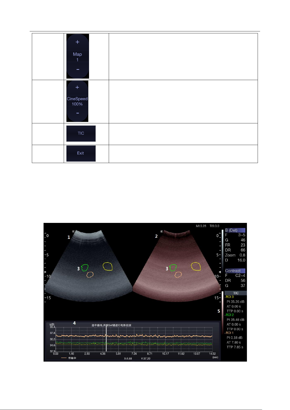
Acclarix LX9 Series Diagnostic Ultrasound System User Manual Imaging
Map
The Gray Map adjusts the post processing map used on the
Contrast image. In general, higher map numbers correspond to
more contrast in the image.
Cine Speed
Adjusts the speed of playing cine loop.
Time
Intensity
Curve
Activates Time Intensity Curve displays. See section 5.11.3 for
details.
Exit
Exits Contrast Imaging mode.
Table 5-13 Touch Screen Controls of Contrast Imaging
5.12.3. Time Intensity Curve (TIC) Analysis
Time Intensity Curve (TIC) quantitatively describes the dynamics of the intravascular ultrasound
contrast agent, and thereby provides a quantitative assessment of blood flow perfusion.
TIC Analysis Screen Display
A example of TIC analysis screen display is shown as the figure below:
Figure 5-10 Example of TIC Analysis Display
- 73 -

Acclarix LX9 Series Diagnostic Ultrasound System User Manual Imaging
No.
Name
Description
1.
Contrast cineloop window
Displays contrast cineloop and ROIs.
2.
Tissue cineloop window
Displays tissue cineloop and ROIs.
3.
ROIs
The ROI indicates sampling position of the TIC. ROIs are
color-coded, and up to 7 ROIs can be displayed.
4.
Analysis window
The TIC Analysis window displays:
Y axis represents intensity scale (dB).
X axis represents time (sec).
Time intensity curves, coded with the same color of its
sample area.
Frame marker, a white vertical line.
Time at the frame marker position.
Intensity at the frame marker position.
The active curve.
5.
TIC parameters
Displays TIC parameters of each sample area (ROI). These
parameters include:
PI (Peak Intensity): contrast peak intensity.
AT (Arrival Time): time point where contrast intensity
appears.
TTP (Time to Peak): time point where the contrast
intensity reaches peak value.
Name
Control
Description
Ellipse tool
Ellipse tool for placing ROIs on contrast image.
Trace tool
Trace tool for placing ROIs on contrast image.
TIC Chart
Show/hide TIC chart. Only available when at least one ROI
is placed on the image. The TIC chart is displayed below
the image area.
Fit Curving
Press to perform fit curving.
Delete
Removes ROIs from the image one by one.
The TIC analysis touch screen displays the following controls:
- 74 -

Acclarix LX9 Series Diagnostic Ultrasound System User Manual Imaging
Exit
Exits TIC Analysis.
Basic TIC Analysis procedures
1. Perform the scanning and inject Contrast agent.
2. Freeze the image or select a range of images for analysis.
Or, Select a desired cine loop from the stored images.
3. Press TIC touch button to activate time intensity curve analysis.
4. Place ROIs (region of interest) on one of these images, and time intensity curves are displayed
below the image area.
Up to 7 ROIs with different colors can be created on the image. Each ROI corresponds to one TIC
displayed in the chart below the image area. The colors of ROI and its TIC are consistent. Two
tools can be used to place ROIs: Ellipse and Trace. Press Ellipse or Trace on the touch screen,
and follow the instructions displayed on the screen to determine the shape of the ROI.
5. Selecting one TIC for analysis.
To select one TIC: press the <Cursor> key on the control panel, move the cursor onto one TIC,
and then press Set key. The currently selected TIC is indicated by "Active" below the TIC chart.
When one TIC is selected, rolling the trackball will move the frame marker and can view the
intensity and time at the frame marker position. Pressing Set key can play the cineloop.
6. If necessary, perform curve fitting.
7. Analyze of the parameters of the curve.
8. Press <Freeze> key or Exit key to exit TIC analysis.
- 75 -

Acclarix LX9 Series Diagnostic Ultrasound System User Manual Imaging
5.13 ECG
The ultrasound system can be configured with an optional ECG module. The ECG module obtains
ECG signals via ECG patient cable to display ECG waveform synchronously with the ultrasound
image. The ECG signals can be used as time reference in cardiac exam for marking the systolic and
end diastolic moments.
WARNING
1. The ECG waveforms displayed on the main screen are not intended for ECG diagnosis and
monitoring.
2. The ECG module and electrodes are not intended for intra-cardiac use or direct cardiac contact.
3. Do not use the ECG function on the patient with pacemaker.
4. Only the ECG module, patient cable and electrodes supplied by EDAN can be used.
5. Only authorized service personnel can service the ECG module.
6. The conductive parts of electrodes and associated connectors, including the neutral electrode,
should not contact any other conductive parts including earth.
7. The electrodes must be removed from the patient before a high-frequency surgical equipment is
used on the patient.
8. The quality of the ECG waveform depends on the stability and conductivity of the electrodes
because patient's movements can cause artifacts.
9. Only the ECG applied part is defibrillation-proof. Please remove transducer and other
accessories from patient before defibrillation. Always refer to the defibrillator's user manual when
performing defibrillation.
10. After defibrillation, the ECG waveform recovers within 10 seconds if the correct electrodes are
used and applied according to the manufacturer's instructions.
11. Always do the follows prior to operation:
Check the patient cable for visible evidence of any damage. If any damage is found, a new
patient cable should be used.
Connect the electrodes to patient correctly following the manufacturer's instruction. If a ECG lead
is off, the ultrasound system will display " ECG Lead Off " message..
12. The disposable electrodes can only be used for one time. Do not use the electrodes passing its
expiry date.
13. The disposable electrodes should be disposed of according to the local regulations.
14. Regularly check, clean and maintain the patient cable and electrodes following the
manufacturer's instruction.
- 76 -

Acclarix LX9 Series Diagnostic Ultrasound System User Manual Imaging
Name
Control
Description
ECG
Displays or hides ECG waveforms and heart rate value on the
main screen.
Gain
Adjusts the gain of ECG waveform.
ECG Lead
Selects the ECG lead from I, II and III lead as the ECG
waveform source.
AC Filter
Selects the AC filter frequency according to the AC power you
use. 50 Hz and 60 Hz are available. This could filter the
interference from AC power supply.
5.13.1. ECG Touch Screen Controls
The following touchscreen controls impact the ECG function:
5.13.2. ECG Basic Operations
1. Invoke ECG function.
Invoke P5-1Q transducer as the currently active transducer. Press ECG on the touch screen to
invoke the ECG function and display ECG controls on the touch screen.
2. Connect patient cable and electrodes.
Connect the patient cable to the ECG connector on the ultrasound system first.
Place electrodes on the patient's body as the figure below (Take 3-lead placement of AHA
standard as an example).
- 77 -

Acclarix LX9 Series Diagnostic Ultrasound System User Manual Imaging
Figure 5-11 3-lead Placement of AHA Standard
3. The image area displays real-time ECG waveform and heart rate value. There is a red mark on
the ECG waveform indicating the temporal position of ultrasound image in relation to the ECG
waveform.
4. Switch imaging modes and adjust relevant parameters to optimize the image.
5. Adjust ECG Gain and select ECG lead if necessary.
6. Freeze the image and review.
7. Exit ECG mode.
Remove electrodes from patient's body and disconnect ECG module from the ultrasound system.
5.13.3. ECG Review
Pressing <Freeze> key will freeze ultrasound image and ECG waveform at the same time. Moving
trackball left or right will playback the ECG waveform and ultrasound image together. The red mark on
the ECG waveform indicates the time of the currently displayed image. In this manner, you can move
the red mark to locate the diastolic or systolic moments and check relevant ultrasound image at that
moment.
- 78 -

Acclarix LX9 Series Diagnostic Ultrasound System User Manual Transducers and Biopsy
No.
Model
Type
Application
Applied Region
1
L17-7HQ
Linear
Small Parts(Thyroid, Testes, Breast)
Peripheral Vascular
Musculoskeletal
Body Surface
2
P5-1Q
Phased array
Adult Cardiac
Abdominal
Pediatric Cardiac
Adult Cephalic
Body Surface
3
E8-4Q
Micro Convex
Fetal / Obstetrics
Trans-vaginal
Trans-rectal
Urology
Gynecology
Intra-cavity
4
C5-2Q
Convex
Abdominal
Fetal / Obstetrics
Urology
Gynecology
Musculoskeletal
Body Surface
5
L12-5Q
Linear
Abdominal
Small parts(Thyroid, Testes, Breast)
Peripheral Vascular,
Musculoskeletal
Body Surface
6
L17-7SQ
Linear
Intra-operative
Musculoskeletal
Peripheral Vascular
Body Surface/
Intra-operative
7
MC8-4Q
Micro Convex
Pediatric
Abdominal
Neonatal Cephalic
Musculoskeletal
Peripheral Vascular
Body Surface
8
MC9-3TQ
Micro Convex
Pediatric
Abdominal
Neonatal Cephalic
Peripheral Vascular
Musculoskeletal
Body Surface
6 Transducers and Biopsy
6.1 Transducer Model
- 79 -

Acclarix LX9 Series Diagnostic Ultrasound System User Manual Transducers and Biopsy
9
P7-3Q
Phased Array
Adult Cardiac
Pediatric
Abdominal
Pediatric Cardiac
Neonatal Cephalic
Body Surface
10
C7-2XQ
Convex
Abdominal
Fetal / Obstetrics
Urology
Gynecology
Musculoskeletal
Body Surface
11
E10-3BQ
Micro Convex
Fetal / Obstetrics
Trans-vaginal
Trans-rectal
Urology
Gynecology
Intra-cavity
12
E10-3HQ
Micro Convex
Fetal / Obstetrics
Trans-vaginal
Trans-rectal
Urology
Gynecology
Intra-cavity
13
C6-2MQ
Convex
Fetal / Obstetrics
Abdominal
Gynecology
Body Surface
14
C5-1Q
Convex
Abdominal
Fetal / Obstetrics
Urology
Gynecology
Musculoskeletal
Body Surface
Table 6-1 Transducer Model & Application
- 80 -

Acclarix LX9 Series Diagnostic Ultrasound System User Manual Transducers and Biopsy
No.
Name
Function
1
Transducer
head
Converts electrical signals to sound waves, and then converts received
echoes back to electrical signals. The tip of the transducer is the acoustic lens.
2.
Center line
mark
Indicates the center line position of the transducer, which are usually used for
out-of-plane needle guide.
3.
Transducer
model
Displays the transducer model.
4
Needle-guided
bracket fixing
tabs and groves
Provides mounting support for the needle-guided bracket.
5.
Transducer
orientation
mark
The side of orientation mark on the transducer corresponds to the side of
orientation mark on the display screen
6
Transducer
cable
Transmits electrical signals between the transducer head and the transducer
connector.
7
Transducer
connector
Connects the transducer to the ultrasound imaging system.
1 2 3 4 5
6
7
6.2 Using Transducers
Understanding a Transducer:
Figure 6-1 takes L12-5Q transducer to show an example of a transducer.
Figure 6-1 Typical transducer
- 81 -

Acclarix LX9 Series Diagnostic Ultrasound System User Manual Transducers and Biopsy
Orientation Mark
Orientation
Mark
Image Orientation Mark
The image orientation marks on the display screen and on the transducer are shown as below. The
side of orientation mark on the transducer corresponds to the side of orientation mark on the display
screen. Ensure orientation marks on the display screen and transducer are on the same side prior to
scanning.
Figure 6-2 Image Orientation Mark
Proper Use of Transducers
To extend the service life and maintain optimum transducer performance, please operate as follows:
Inspect transducer cable, socket and acoustical window of the transducer periodically.
Shut down the machine before connecting or disconnecting the transducer.
Do not drop the transducer onto the floor or collide with hard objects. Otherwise it will be
damaged easily.
Do not heat the transducer.
Do not pull or bend the transducer cable.
Coupling gel can only be used on the head of the transducer, and it should be wiped off after use.
Clean and disinfect the transducer after every use.
The acoustical window and the shell of the transducer should be examined frequently.
CAUTION
1. Do not disinfect or clean transducers under high temperature. The temperature should be below
45°C.
2. To avoid damaging the device, the disinfection method is limited to regular maintenance of
devices in hospitals. Disinfecting instruments should be cleaned first.
3. The coupling gel adapted to the transducer is a medical ultrasound coupling gel. Use only
ultrasound coupling gel that complies with local regulations.
- 82 -

Acclarix LX9 Series Diagnostic Ultrasound System User Manual Transducers and Biopsy
Use of Transducer sheath
CAUTION
1. Always wear gloves to perform the following steps.
2. To minimize disease transmission, legally marketed, sterile transducer sheath is required to use
for intra-cavitary and intra-operative procedures.
3. Use a pyrogen-free transducer sheath for intra-operative procedures.
4. DO NOT use an expired transducer sheath. Check whether the term of validity has expired prior
to using transducer sheaths.
5. The single-use sheath should comply with the local regulations.
6. Before cleaning or disinfecting the transducer, remove the sheath gently and discard it. Put on a
new single-use sheath before using the transducer.
7. Use of protective sheath with natural rubber latex may lead to a severe anaphylactic reaction in
persons sensitive to the natural latex protein.
8. Transducer sheath should be used with all clinical situations where infection is a concern.
To install transducer sheath:
1. Place an adequate amount of sterile coupling gel in the protective sheath and/or on the acoustic
window of the transducer;
2. Insert the transducer into the sheath;
3. Pull the sheath over the transducer and cable until the sheath is fully extended. Check and
eliminate bubbles between the surface of the transducer and the sheath. Be careful not to pierce
the sheath.
4. Secure the sheath using the bands or clips supplied with the sheath;
5. Inspect the sheath to ensure that there are no damages (i.e. holes or tears).
- 83 -

Acclarix LX9 Series Diagnostic Ultrasound System User Manual Transducers and Biopsy
Transducer Applied Region
Transducer Type
Disinfecting Intensity
Disinfecting Method
Contact intact body surface
Body surface
LLD
Spraying or wiping
Contact mucous membrane
Intra-cavity
HLD
Immersion
6.3 Transducer Cleaning and Disinfecting
Transducers should be cleaned and/or disinfected as necessary or between use with a recommended
cleanser or disinfectant. Disconnect the transducer from the system prior to cleaning and disinfecting.
6.3.1. Cleaning
The validated cleaning agents for cleaning the transducers are:
Ethanol (75%)
Isopropanol (70%)
Cleaning agents should be applied and removed using a clean, soft, sterile, non-abrasive cloth or
paper towel.
To clean the transducers:
1. Disconnect the transducer from the system.
2. Wear sterile protective gloves to prevent infection.
3. Remove all residual foreign matters from the transducer using sterile cloth or paper towel
immediately after examination. For the situation where a protective sheath is used, the protective
sheath should be removed first and discarded.
4. Wipe the surface of transducer and cable with a sterile cloth dampened with the cleaning solution
until no visible contaminants remain.
5. After cleaning, wipe off the cleaning solution with a new sterile cloth dampened with tap water
until no visible cleaning agent remains.
6. Wipe off with a dry sterile cloth to remove residual moisture.
7. Leave the transducer to air dry.
8. If the transducer is not visually clean at the end of the cleaning steps, please repeat the cleaning
steps through step 4 to step 7.
9. Inspect the transducer to ensure that there is no damage. The transducer should be disposed of
properly when any damage is found.
WARNING
1. Unplug the transducer from the system prior to cleaning or disinfecting.
2. To avoid infection, always use protective gloves when performing cleaning and disinfecting
procedures.
3. Prohibit infiltration of any type of liquid into the device or the transducer.
6.3.2. Disinfection
Selecting a proper way to disinfect your transducers based on your transducer applied region:
- 84 -

Acclarix LX9 Series Diagnostic Ultrasound System User Manual Transducers and Biopsy
Contact normally sterile tissue
Intra-operative
Sterilization
Immersion
Note:
LLD=Low-level Disinfection; HLD=High-level disinfection
Disinfectants
Disinfecting Intensity
Disinfecting Method
Ethanol (75%)
LLD
Spraying or wiping
Isopropanol (70%)
LLD
Spraying or wiping
Cidex OPA (0.55%)
HLD
Immersion
Cidex Glutaraldehyde(2.4%)
HLD, Sterilization
Immersion
The validated disinfectants for transducer are:
WARNING
1. Unplug the transducer from the system prior to cleaning or disinfecting.
2. To avoid infection, always use protective gloves when performing cleaning and disinfecting
procedures.
3. To avoid infection, ensure that expiration date of the disinfecting solution has not passed.
4. Please cleaning the transducer prior to disinfection.
Disinfecting by spraying or wiping:
1. Disconnect the transducer from the system.
2. Wear protective gloves to prevent infection.
3. Clean and dry the transducer according to the methods in section
6.3.1 Cleaning
.
4. Prepare the disinfectant solution (75% ethanol or 70% isopropanol).
5. Spray the solution to the transducer interface or wipe it with a sterile cloth dampened with the
disinfectant solution. Follow the disinfectant manufacturer's recommended contact time and
mode.
6. Rinse the transducer according to the disinfectant instructions. Wipe the transducer with a dry
sterile cloth or leave the transducer to air dry.
7. Inspect the transducer to ensure that there is no damage.
Note:
If Ethanol or Isopropanol is used for both cleaning and disinfecting, then a new sterile cloth is required
for the disinfection step.
Disinfecting by Immersion:
1. Disconnect the transducer from the system.
2. Wear protective gloves to prevent infection.
3. Clean and dry the transducer according to the methods in section
4. Prepare the disinfectant solution (Cidex OPA 0.55% or Cidex Glutaraldehyde 2.4%). Refer to the
- 85 -
6.3.1 Cleaning
.

Acclarix LX9 Series Diagnostic Ultrasound System User Manual Transducers and Biopsy
L17-7SQ
Disinfectant
E8-4Q
E10-3HQ
E10-3BQ
instructions provided by the disinfectant manufacturer for the concentration of the disinfection
solution, method of dilution, method of disinfection, temperature and cautions during use.
5. Place the cleaned and dried transducer in contact with the disinfectant (refers to figure 6-3 for the
contacting area) for the time specified by the disinfectant manufacturer. For example, the contact
time recommended by the manufacturer for soaking in Cidex Glutaraldehyde(2.4%) is at least 45
min.
6. Rinse the transducer thoroughly with sterile water to remove all chemical residues. For example,
it is required to flush the transducer after soaking in Cidex Glutaraldehyde(2.4%) with plenty of
sterile water (about 2 gallons) at least one time. Or, follow the complete rinsing instructions
provided by the disinfectant manufacturer to rinse the transducer.
7. Wipe off the water on the transducer with a dry sterile cloth. Leave the transducer to air dry.
8. Inspect the transducer to ensure that there is no damage.
Figure 6-3 Depth of the Transducer Immerged into Disinfectant
WARNING
1. Do not immerse the transducer connector. If the cable connector is immersed, do not plug the
connector into the system. Rinse the connector under running water and dry it thoroughly. If
necessary, contact EDAN for service.
2. Prohibit infiltration of any type of liquid into the device or the transducer.
3. Do not immerse the cable and connector of the transducer into solutions. Transducers can be
submerged to, but not including, the strain relief of the transducer array. Do not immerse or soak
any part of a transducer in any cleaning material not listed in the recommended list of disinfectant.
4. Use the immersion method to disinfect the intra-cavitary and intra-operative transducers.
5. Only non-immersion method can be used with solution of ethanol or isopropanol. The solution
concentration should not exceed the value provided above.
- 86 -

Acclarix LX9 Series Diagnostic Ultrasound System User Manual Transducers and Biopsy
6. The immersion time should not exceed the time that is specified by the disinfectant manufacturer.
7. Patient contact area should be immersed into the solution while using the immersion method, but
should not exceed the depth shown in figure 6-3.
6.3.3. Sterilization
Intra-operative transducers must be sterilized after each exam.
Sterilizing the transducers:
1. Disconnect the transducer from the system.
2. Wear protective gloves to prevent infection.
3. Clean and dry the transducer according to the methods in section
4. Prepare the disinfectant solution (Cidex Glutaraldehyde 2.4%). Refer to the instructions provided
by the disinfectant manufacturer for the concentration of the disinfection solution, method of
dilution, method of disinfection, temperature and cautions during use.
5. Place the cleaned and dried transducer in contact with the disinfectant (refers to figure 6-2 for the
contacting area) for 10 hours. Or, follow the time specified by the disinfectant manufacturer to
soak the transducer.
6. Flush the transducer with plenty of sterile water (about 2 gallons) at least one time. Or, follow the
complete rinsing instructions provided by the disinfectant manufacturer to rinse the transducer.
7. Wipe off the water on the transducer with a dry sterile cloth. Leave the transducer to air dry.
8. Inspect the transducer to ensure that there is no damage.
WARNING
1. Do not sterilize the transducer using techniques such as autoclave, ultraviolet, gamma radiation,
gas, steam, or heat. Severe damage may result.
2. If L17-7SQ transducer is applied to normally sterile tissue without using a sterile sheath, it must be
sterilized. If L17-7SQ transducer is applied to normally sterile tissue using a sterile sheath, it
should be sterilized, or disinfected(High-level disinfection).
6.3.1 Cleaning
.
6.3.4. Storage
WARNING
1. Dry the transducer after high-level disinfection or sterilization and store it in sterile environment.
2. Do not use the carrying case for storing the transducer, because the carrying case may become a
source of infection.
1. Ensure the transducer is cleaned, disinfected, sterilized and completely dried before storage.
2. Store the transducer in a sterile environment or in a disposable sterile package.
3. Store the transducer under the following conditions:
a) Atmospheric Temp.: -20℃〜+55℃
b) Relative Humidity: 15%~95% (Non-condensing)
c) Atmospheric Pressure: 70kPa ~ 106kPa.
- 87 -

Acclarix LX9 Series Diagnostic Ultrasound System User Manual Transducers and Biopsy
6.4 Needle Biopsy Guide
NOTE:
Use proper sterile technique at all times when performing a biopsy.
Always follow these basic precautions:
WARNING
1. Disinfect the needle guide kit before the first use and after each subsequent use.
2. Calibrate the needle guide kit (see section 6.4.3) under any of the following conditions:
a) The first time that each bracket/transducer combination is used.
b) If the bracket or transducer head is dropped or struck, or has evidence of wear.
c) If previous use has shown some drift of the needle from the center of the guidelines.
3. The displayed needle guide pathway on the EDAN video monitor is intended for reference during
biopsy procedures. A variety of factors outside EDAN‟s control, such as changing tissue density,
bending of the needle, off-axis pressure by the person holding the transducer, etc., may cause
deflection of a needle outside of the displayed video pathway even when the transducer, needle
guide, and the system software are all performing as intended and within manufacturing
specification. The specialist performing a biopsy procedure must be aware of potential external
factors when performing an invasive procedure.
4. Do not freeze the system when performing a biopsy.
5. EDAN needle guides are designed and manufactured to attach firmly to designated transducers
and should not require excessive force to assemble or disassemble. Do not use a needle guide
that requires excessive force or manipulation to assemble or disassemble.
6. A single-use sheath should be used on transducer when performing a biopsy.
6.4.1. Installing Needle Guide Bracket
WARNING
1. For illustration purpose only, transducer and bracket may be shown without a protective sheath.
Always place a protective sheath on transducer and bracket to protect cross infection.
BGK-C5-2/BGK-L40UB/ BGK-R15UB/ BGK-004/BGK-007
The installation steps for these brackets are the same. Here we take one bracket for illustration.
- 88 -

Acclarix LX9 Series Diagnostic Ultrasound System User Manual Transducers and Biopsy
Clamp
Locking Knob
Adjusting Knob
Needle Guide Path
Tab Release
Angle Knob
Structures:
Installation and Use Steps:
1. Place an appropriate amount of gel on transducer surface, and insert transducer into the sheath.
2. Loosen the locking knob to open the clamp of bracket. Attach the bracket to the transducer by
aligning the locating markers on the bracket and the transducer. Properly secure the clamp of
bracket with the locking knob. Ensure the backet is firmly attached.
3. Loosen the angle knob to select a needle guide angle, and secure the angle knob.
4. Press the tab release and place the biopsy needle into the needle guide path. Use the adjusting
knob to properly secure the needle.
- 89 -

Acclarix LX9 Series Diagnostic Ultrasound System User Manual Transducers and Biopsy
Clamp
Needle Guide Path
Locking Knob
5. After biopsy, press the tab release to remove the needle, and loosen the locking knob to remove
the bracket from the transducer.
BGK-CR10UA
Structures:
Installation and Use Steps:
1. Place an appropriate amount of gel on transducer surface, and insert transducer into the sheath.
2. Loosen the locking knob to open the clamp of bracket. Attach the bracket to the transducer by
aligning the locating markers on the bracket and the transducer.
- 90 -

Acclarix LX9 Series Diagnostic Ultrasound System User Manual Transducers and Biopsy
Needle Guide Path
Clamp
Quick Release
3. Properly secure the clamp of bracket with the locking knob. Ensure the backet is firmly attached,
and then place the biopsy needle into the needle guide path.
BGK-005/BGK-006
The installation steps for these brackets are the same. Here we take one bracket for illustration.
Structures:
Installation and Use Steps:
1. Place an appropriate amount of gel on transducer surface, and insert transducer into the sheath.
2. Use the quick release to open the clamp of bracket. Align the locating markers on the bracket and
the transducer and push the bracket to click into place.
- 91 -

Acclarix LX9 Series Diagnostic Ultrasound System User Manual Transducers and Biopsy
3. Press the left and right side of the clamp as the figure below to attach the bracket to the
transducer firmly.
4. Ensure the bracket is firmly attached, and then place the biopsy needle into the needle guide
path.
BGK-001
Structures:
Installation and Use Steps:
1. Place an appropriate amount of gel on transducer surface, and insert transducer into the sheath.
- 92 -

Acclarix LX9 Series Diagnostic Ultrasound System User Manual Transducers and Biopsy
Specification
Depth
21G(1.0cm)
0.8 - 1.2 cm
21G(1.5cm)
1.3 - 1.7 cm
21G(2.0cm)
1.8 - 2.2 cm
2. Loosen the locking knob to open the clamp bracket. Attach the bracket to the transducer by
aligning the locating markers on the bracket and the transducer. Properly secure the clamp of
bracket with the locking knob.
3. Install the disposable Needle Guide.
a. Select appropriate disposable needle guide to achieve target depth from skin line:
b. Install the needle guide to the needle guide holder, and then put in the biopsy needle:
- 93 -

Acclarix LX9 Series Diagnostic Ultrasound System User Manual Transducers and Biopsy
6.4.2. Activating Needle Guide Function
To enable the needle guide function:
1. In the B mode imaging, press Needle button on touch screen, A needle touch screen UI is
displayed, Press Enable button to active the Needle Guide function.
2. Press Double Line button to switch double line and single line as the Needle guide Line
graphics.
3. Some needle guide brackets support multiple angles. If the current transducer supports such a
guide then the Line paddle key appears. Pressing it selects guide lines of different angles.
Each line represents a corresponding angle marked on the needle guide bracket.
Figure 6-4 Needle Guide Touch Screen
WARNING
1. To avoid patient injury when using a multi-angle bracket, make sure that the same angle(A, B, C
or D) is selected on both the bracket and the ultrasound system.
NOTE:
The distance between each dot of the needle guide line indicates 0.5 cm.
6.4.3. To Adjust the Needle Guide Line
WARNING
1. Calibrate the needle guide under any of the following conditions:
a) The first time a needle guide is used with a given transducer.
b) Any time the needle guide or transducer has been dropped or struck against a hard surface.
c) After repeated use.
2. Do not use the needle guide bracket if the needle does not track with the guide during calibration.
- 94 -

Acclarix LX9 Series Diagnostic Ultrasound System User Manual Transducers and Biopsy
Angle Line
Figure 6-5 Needle Guide Calibration Touch Screen
To calibrate the guide line
1. Assemble the needle guide bracket on the transducer, and use the transducer to image a water
bath or needle guide phantom.
2. From the Needle function on the B-mode touch screen, press the Line paddle key to select a
guide line.
3. Press the Calibration button on the touch screen to display the Angle and Position paddle
button.
Use the Position paddle to adjust the line horizontally until the origin aligns with the actual
needle.
Use the Angle paddle or Angle knob to adjust the angle of the line until the entire line
aligns with the actual needle.
4. Any changes will be saved as the default value automatically.
6.5 Needle Visualization
Needle Visualization is an image processing technology that enhances needle visibility. It is available
in B-mode for all linear transducers.
Figure 6-6 Needle Enhancement Visualization
- 95 -

Acclarix LX9 Series Diagnostic Ultrasound System User Manual Transducers and Biopsy
Needle Visualization is invoked by pressing the Needle button on B-mode touch screen, and then
the Enable button in the Needle Visualization section of the Needle touch screen. The following
parameters can be adjusted when it is active.
Enable: Enables or disables Needle Visualization.
L/R: press to display the angle line on left side or right side of the image field.
Shallow/Medium/Steep: press to enhance the needle visibility for different needle inserted
angles: 16° (Shallow), 24° (Medium) and 40° (Steep). For best results use the angle line that
is closest to perpendicular to the needle path.
Figure 6-7 Touch Screen for Needle Enhancement Visualization
6.6 Center Line
The Center Line is a vertical dotted line displayed at the middle of the image field, representing the
middle of ultrasound beam. The Center Line helps to locate the position and depth of a target disease
focus for out-of-plane biopsy, lithotripsy and etc..
To use Center Line:
1. Press Center-Line on B-mode touch screen to activate Center Line.
2. A dotted center line is displayed vertically at the middle of the image field. The position and
direction of the center line cannot be changed.
3. Move the transducer to locate the target.
4. Use distance measurement to obtain the depth of the target.
Note:
Center Line is not available on Intro-cavity transducers.
6.7 Needle Guide Bracket Cleaning and Sterilization
NOTE:
1. Use proper sterilization technique at all times when performing a biopsy.
2. Ensure that protective gloves are worn.
WARNING
1. The needle guide bracket kits are not disinfected or sterilized before delivery. The operators must
clean and sterilize the needle guide bracket kits before and after each use.
2. Inspect the bracket for damage such as cracks or breakage. If damage is evident, discontinue
use of bracket and contact your Edan representative for disposal guidance.
3. Sterilize the bracket before disposal or sending back to manufacturer for repair.
- 96 -

Acclarix LX9 Series Diagnostic Ultrasound System User Manual Transducers and Biopsy
6.7.1. Cleaning
1. Wear sterile protective gloves to prevent infection.
2. Disconnect the needle guide bracket from the transducer after each use, and remove all visible
residues from the needle guide bracket using a small and soft-bristled brush or other similar
devices. Do the cleaning quickly before the needle guide bracket dries out.
3. Soak the needle guide bracket in the cleaning solution (Ethanol 75% or Isopropanol 70%) for at
least five minutes. Use a soft-bristled brush to clean the needle guide bracket during the soaking.
4. Take out the needle guide bracket from the cleanser and wipe all residues with a sterile cloth.
5. Let the bracket air dry, or dry the bracket with a sterile cloth.
6. If the bracket is not visually clean at the end of the cleaning steps, please repeat the cleaning
steps through step 3 to step 5.
7. Inspect the bracket to ensure that there is no damage. The bracket should be disposed of properly
when any damage is found.
6.7.2. Sterilization
1. Wear sterile protective gloves to prevent infection.
2. Disconnect the bracket from the transducer, and remove all visible residues from the bracket using
sterile cloth.
3. Clean and dry the bracket according to the methods in section
4. Sterilize the bracket assembly by dynamic air removal steam sterilizer for at least four minutes at
132oC. Dry the bracket for at least 30 min after sterilization.
5. Inspect the bracket to ensure that there is no damage.
6.7.1 Cleaning
.
6.7.3. Storage
WARNING
1. Dry the bracket after sterilization and store it in sterile environment.
2. Do not use the carrying case for storing the bracket, because the carrying case may become a
source of infection.
1. Ensure the bracket is cleaned, sterilized and completely dried before storage.
2. Store the bracket in a sterile environment or in a disposable sterile package.
3. Store the bracket under the following conditions:
a) Atmospheric Temp.: -20℃〜+55℃
b) Relative Humidity: 15%~95% (Non-condensing)
c) Atmospheric Pressure: 70kPa ~ 106kPa.
- 97 -
 Loading...