

Page 1
Page 2

About this Manual
P/N: 01.54.456527
MPN: 01.54.456527011
Release Date: January 2015
© Copyright EDAN INSTRUMENTS, INC. 2014-2015. All rights reserved.
Statement
This manual will help you understand the operation and maintenance of the product better. It is
reminded that the product shall be used strictly complying with this manual. User’s operation
failing to comply with this manual may result in malfunction or accident for which EDAN
INSTRUMENTS, INC. (hereinafter called EDAN) can not be held liable.
EDAN owns the copyrights of this manual. Without prior written consent of EDAN, any
materials contained in this manual shall not be photocopied, reproduced or translated into other
languages.
Materials protected by the copyright law, including but not limited to confidential information
such as technical information and patent information are contained in this manual, the user shall
not disclose such information to any irrelevant third party.
The user shall understand that nothing in this manual grants him, expressly or implicitly, any
right or license to use any of the intellectual properties of EDAN.
EDAN holds the rights to modify, update, and ultimately explain this manual.
Responsibility of the Manufacturer
EDAN only considers itself responsible for any effect on safety, reliability and perform ance of
the equipment if:
Assembly operations, extensions, re-adjustments, modifications or repairs are carried out by
persons authorized by EDAN, and
The electrical installation of the relevant room complies with national standards, and
The instrument is used in accordance with the instructions for use.
Upon request, EDAN may provide, with compensation, necessary circuit diagrams, and other
information to help qualified technician to maintain and repair some parts, which EDAN may
I
Page 3

define as user serviceable.
Terms Used in th is Manual
This guide is designed to give key concepts on safety precautions.
WARNING
A WARNING label advises against certain actions or situations that could result in personal
injury or death.
CAUTION
A CAUTION label advises against actions or situations that could damage equipment, produce
inaccurate data, or invalidate a procedure.
NOTE
A NOTE provides useful information regarding a function or a procedure.
II
Page 4

Table of Contents
Chapter 1 Intended Use and Safety Guidance ............................................................................ 1
1.1 Intended Use/Indications for Use ........................................................................................ 1
1.2 Safety Guidance .................................................................................................................. 1
1.3 Explanation of Symbols on the Telemetry transmitter ........................................................ 6
Chapter 2 Overview ....................................................................................................................... 8
2.1 System Introduction ............................................................................................................ 8
2.2 Display Screen of Telemetry Transmitter............................................................................ 8
2.2.1 Default Interface........................................................................................................ 8
2.2.2 Main Interface ........................................................................................................... 9
2.2.3 Setting Interface ...................................................................................................... 12
2.3 Appearance of Telemetry T ransmitter ............................................................................... 12
2.3.1 Front View ............................................................................................................... 12
2.3.2 Rear View ................................................................................................................ 14
2.3.3 Left Side View ......................................................................................................... 15
2.3.4 Right Side View ...................................................................................................... 15
2.3.5 T op View ................................................................................................................. 16
2.3.6 Bottom View ........................................................................................................... 16
2.4 Configuration .................................................................................................................... 16
2.5 Display Screens of the MFM-CMS................................................................................... 17
2.5.1 Overview ................................................................................................................. 17
2.5.2 Main Screen ............................................................................................................ 17
2.5.3 Auxiliary Screen ...................................................................................................... 20
2.5.4 Large Font Display .................................................................................................. 22
2.5.5 Layout of Patient Sectors ........................................................................................ 23
Chapter 3 Installation of Telemetry Monitoring System .......................................................... 24
3.1 Initial Inspection................................................................................................................ 24
3.2 Installation Environment ................................................................................................... 24
3.3 Power Supply Requirement............................................................................................... 24
3.4 Wireless Network .............................................................................................................. 25
3.5 Installation Method ........................................................................................................... 25
3.6 Checking the Printer .......................................................................................................... 26
3.7 Checking the Telemetry Monitoring System .................................................................... 26
3.8 Setting Date and Time ....................................................................................................... 26
III
Page 5

3.9 Handing Over the Central Monitoring Systerm ................................................................ 27
Chapter 4 Basic Operations ........................................................................................................ 29
4.1 Basic Operations for Telemetry Transmitter ..................................................................... 29
4.1.1 Battery Installing and Replacing ............................................................................. 29
4.1.2 Switching On ........................................................................................................... 30
4.1.3 Switching Off .......................................................................................................... 30
4.1.4 Open/ Close Screen ................................................................................................. 30
4.1.5 Leather Cover Wearing ........................................................................................... 31
4.1.6 Nurse Call ............................................................................................................... 31
4.2 Basic Operations for MFM-CMS ..................................................................................... 31
4.2.1 Mouse Operation ..................................................................................................... 31
4.2.2 Switching on/off the MFM-CMS ............................................................................ 32
Chapter 5 Patient Management .................................................................................................. 34
5.1 Admitting a Patient ............................................................................................................ 34
5.2 Changing Patient Information ........................................................................................... 34
5.3 Switching Patient sector .................................................................................................... 35
5.4 Discharging a Patient ........................................................................................................ 35
5.5 Transferring a Patient ........................................................................................................ 35
5.6 Monitoring Statistics ......................................................................................................... 35
5.7 Nurse Call / Patient Call .................................................................................................... 36
Chapter 6 Patient Sector ............................................................................................................. 37
6.1 Overview ........................................................................................................................... 37
6.2 Networked Monitoring Display ........................................................................................ 37
6.3 Menu in the Patient Sector ................................................................................................ 39
6.4 Parameter/ Waveform Setup .............................................................................................. 39
6.4.1 Setting W aveforms .................................................................................................. 39
6.4.2 Setting Parameters ................................................................................................... 40
6.5 Freeze ................................................................................................................................ 40
6.6 Real-Time Printing ............................................................................................................ 40
6.7 Alarm Reset ....................................................................................................................... 41
Chapter 7 Viewing Single Bed ..................................................................................................... 42
7.1 Display of Single Bed ....................................................................................................... 42
7.2 Hiding/Showing Multi-Lead W aveform ........................................................................... 43
7.3 Short Trend Review .......................................................................................................... 43
7.4 OxyCRG ............................................................................................................................ 44
IV
Page 6

7.5 Freeze ................................................................................................................................ 44
Chapter 8 Setting T elemetry T ransmitters via MFM-CMS .............................................................. 45
8.1 Changing Patient Information ........................................................................................... 45
8.2 Setting Parameters ............................................................................................................. 45
8.2.1 Parameters Alarm Setting ........................................................................................ 46
8.2.2 Physiological Parameter Attribute and Configuration ............................................ 46
Chapter 9 Review ......................................................................................................................... 47
9.1 Patient List ........................................................................................................................ 47
9.1.1 Patient Review ........................................................................................................ 47
9.1.2 History Patient Review ........................................................................................... 47
9.1.3 Backup Patient Review ........................................................................................... 48
9.2 W a ve Review ..................................................................................................................... 48
9.2.1 Reviewing Normal W a vefor ms ............................................................................... 48
9.2.2 Reviewing Compressed Waveforms ....................................................................... 48
9.2.3 Setting Wave Speed ................................................................................................. 49
9.2.4 Refreshing W aveform ............................................................................................. 49
9.2.5 Selecting W aveform ................................................................................................ 49
9.2.6 Print ......................................................................................................................... 49
9.3 Alarm Review.................................................................................................................... 49
9.3.1 Locking and Unlocking Alarm Information ............................................................ 49
9.3.2 Printing Alarm Information ..................................................................................... 50
9.3.3 Sequencing the Alarm List ...................................................................................... 50
9.3.4 Annotating Alarm .................................................................................................... 50
9.3.5 Filtering Alarm Events ............................................................................................ 50
9.4 Trend Review .................................................................................................................... 51
9.4.1 Setting Resolution ................................................................................................... 51
9.4.2 Viewing Parameters selectively .............................................................................. 51
9.4.3 Refreshing Data ....................................................................................................... 51
9.4.4 Printing Trend Review ............................................................................................ 51
9.4.5 Selecting Trend Table, Trend Graph ....................................................................... 51
Chapter 10 System Setup ............................................................................................................. 52
10.1 Common Setup ................................................................................................................ 52
10.1.1 Color Setup ........................................................................................................... 52
10.1.2 Display Setup ........................................................................................................ 52
10.1.3 T elemetry Module Switch Setup ........................................................................... 52
V
Page 7

10.1.4 Help ....................................................................................................................... 53
10.2 User Maintain .................................................................................................................. 53
10.2.1 Telemetry Transmitter Batch Settings ................................................................... 53
10.2.2 Telemetry Alar m Latch Setup ............................................................................... 53
10.2.3 Date/Time Setup .................................................................................................... 54
10.2.4 MFM-CMS System Alarm Setup .......................................................................... 54
10.2.5 Changing Language .............................................................................................. 54
10.2.6 HL7 ....................................................................................................................... 54
10.2.7 Database Maintain ................................................................................................. 55
10.2.8 Other Setups .......................................................................................................... 55
10.2.9 User Password Setting........................................................................................... 55
10.2.10 About ................................................................................................................... 55
Chapter 11 Alarm Management ................................................................................................. 56
11.1 Overview ......................................................................................................................... 56
11.1.1 Physiological Alarms............................................................................................. 56
11.1.2 T echnical Alarms ................................................................................................... 56
11.1.3 Prompts.................................................................................................................. 57
11.2 Alarm Levels ................................................................................................................... 57
11.3 Parameters Alarm Setting ................................................................................................ 57
11.4 Alarm Mute ..................................................................................................................... 57
11.5 Audio Pause ..................................................................................................................... 58
11.6 Alarm Prompt/Response .................................................................................................. 58
11.7 T esting Alarms ................................................................................................................. 59
11.8 Alarms for Networking Status ......................................................................................... 60
Chapter 12 Alarm Information ................................................................................................... 61
12.1 Physiological Alarm Information .................................................................................... 61
12.2 Technical Alarm Information .......................................................................................... 63
12.3 Prompts ........................................................................................................................... 66
12.4 Adjustable Range of Alarm Limits .................................................................................. 66
Chapter 13 Printing ..................................................................................................................... 68
13.1 Printing Report with a Printer ......................................................................................... 68
13.2 Printing Preview/ Printing Settings ................................................................................. 68
13.2.1 Printing Preview .................................................................................................... 68
13.2.2 Printing Settings .................................................................................................... 68
13.3 Exporting the PDF File ................................................................................................... 68
VI
Page 8

Chapter 14 Database Management ............................................................................................ 70
14.1 Database Backup ............................................................................................................. 70
14.2 Reviewing Backup Database........................................................................................... 70
Chapter 15 Monitoring ECG ...................................................................................................... 71
15.1 Overview ......................................................................................................................... 71
15.2 ECG Safety Information ................................................................................................. 71
15.3 ECG Display ................................................................................................................... 72
15.3.1 ECG Display on Telemetry Transmitter Screen .................................................... 72
15.3.2 ECG Display on MFM-CMS ................................................................................ 73
15.4 Selecting Calculation Lead ............................................................................................. 73
15.5 Changing Size of ECG Waveform .................................................................................. 74
15.6 Changing ECG Filter Settings ......................................................................................... 74
15.7 ECG Alarm Settings ........................................................................................................ 74
15.8 Monitoring Procedure ..................................................................................................... 75
15.8.1 Preparation ............................................................................................................ 75
15.8.2 Connecting ECG Cables ....................................................................................... 75
15.9 Installing Electrodes ........................................................................................................ 75
15.9.1 Electrode Placement for 3-lead ............................................................................. 76
15.9.2 Electrode Placement for 5-lead ............................................................................. 76
15.10 Setting Alarm Source .................................................................................................... 78
15.11 Smart Lead Off .............................................................................................................. 78
15.12 Setting Pace Status ........................................................................................................ 79
15.13 ECG Calibration ............................................................................................................ 79
15.14 ECG Waveform Settings ............................................................................................... 79
15.15 ST Segment Monitoring ................................................................................................ 80
15.15.1 Open/ Close ST Analysis .................................................................................... 80
15.15.2 ST Display ........................................................................................................... 80
15.15.3 ST Alarm Settings ............................................................................................... 80
15.15.4 About ST Measurement Points ............................................................................ 80
15.16 Arr . Monitoring ............................................................................................................. 81
15.16.1 Arrhythmia Analysis ........................................................................................... 81
15.16.2 ARR Analysis Menu ............................................................................................ 82
Chapter 16 Monitoring RESP ..................................................................................................... 84
16.1 Overview ......................................................................................................................... 84
16.2 RESP Safety Information ................................................................................................ 84
VII
Page 9

16.3 Electrode Placement for Monitoring RESP .................................................................... 84
16.4 Cardiac Overlay .............................................................................................................. 85
16.5 Chest Expansion .............................................................................................................. 85
16.6 Abdominal Breathing ...................................................................................................... 85
16.7 Selecting RESP Lead ...................................................................................................... 85
16.8 Changing the Apnea Time ............................................................................................... 85
16.9 Changing the Size and Speed of the Respiration Waveform .......................................... 86
16.10 RESP Alarm Settings .................................................................................................... 86
Chapter 17 Monitoring SpO2 ...................................................................................................... 87
17.1 Overview ......................................................................................................................... 87
17.2 SpO2 Safety Information ................................................................................................. 87
17.3 Measuring SpO2 .............................................................................................................. 88
17.4 Measurement Procedure .................................................................................................. 88
17.5 Assessing the Validity of a SpO2 Reading ....................................................................... 89
17.6 SpO2 Alarm Delay ........................................................................................................... 90
17.7 Setting Sensitivity ........................................................................................................... 90
17.8 SpO2 Alarm Settings ....................................................................................................... 90
Chapter 18 Monitoring PR .......................................................................................................... 91
18.1 Overview ......................................................................................................................... 91
18.2 Selecting the Active Alarm Source ................................................................................. 91
18.3 PR Alarm Settings ........................................................................................................... 91
Chapter 19 Using Battery ............................................................................................................... 92
19.1 Battery Status on Screen ................................................................................................. 92
19.2 Replacing the Battery ...................................................................................................... 94
19.3 Recycling the Battery ...................................................................................................... 94
Chapter 20 Safety ......................................................................................................................... 95
20.1 Control and Safety Index ................................................................................................ 95
20.2 Characteristics ................................................................................................................. 95
Chapter 21 Care and Cleaning ................................................................................................... 96
21.1 General Points ................................................................................................................. 96
21.2 Cleaning .......................................................................................................................... 96
21.2.1 Cleaning the T e lemetry Transmitter ...................................................................... 97
21.2.2 Cleaning the Reusable Accessories ....................................................................... 97
21.3 Disinfection ..................................................................................................................... 98
21.3.1 Disinfecting the Telemetry Transmitter................................................................. 98
VIII
Page 10

21.3.2 Disinfecting the Reusable Accessories.................................................................. 98
Chapter 22 Maintenance ........................................................................................................... 100
22.1 Inspecting ...................................................................................................................... 100
22.2 Maintenance Task and Test Schedule ............................................................................ 100
Chapter 23 Warranty and Service ............................................................................................ 101
23.1 W a rranty ........................................................................................................................ 101
23.2 Contact information ...................................................................................................... 101
Chapter 24 Accessories .............................................................................................................. 102
24.1 ECG Accessories ........................................................................................................... 102
24.2 SpO2 Accessories .......................................................................................................... 103
24.3 Other Accessories .......................................................................................................... 104
A Product Specifications ............................................................................................................ 105
A.1 Classification of Telemetry Transmitter ......................................................................... 105
A.2 Specifications of Telemetry Transmitter ........................................................................ 105
A.2.1 Physical Specifications ......................................................................................... 105
A.2.2 Environmental Specifications .............................................................................. 105
A.2.3 Display Specifications .......................................................................................... 106
A.2.4 Battery .................................................................................................................. 106
A.3 Data Storage ................................................................................................................... 107
A.4 Specifications of MFM-CMS ......................................................................................... 107
A.4.1 Recommended Hardware Configuration .............................................................. 107
A.4.2 Software Performance .......................................................................................... 109
A.5 ECG ................................................................................................................................ 109
A.6 RESP .............................................................................................................................. 114
A.7 SpO2 ............................................................................................................................... 115
A.8 Wi-Fi............................................................................................................................... 116
B EMC Information ................................................................................................................... 117
B.1 Electromagnetic Emissions ............................................................................................ 117
B.2 Electromagnetic Immunity ............................................................................................. 117
B.3 Electromagnetic Immunity ............................................................................................. 119
B.4 Recommended Separation Distances ............................................................................. 120
C Default Settings ....................................................................................................................... 122
C.1 Patient Information Default Settings .............................................................................. 122
C.2 Alarm Default Settings (MFM-CMS) ............................................................................ 122
C.3 ECG Default Settings ..................................................................................................... 122
IX
Page 11

C.4 RESP Default Settings .................................................................................................... 123
C.5 SpO2 Default Settings ..................................................................................................... 124
C.6 PR Default Settings ........................................................................................................ 124
D Abbreviation ........................................................................................................................... 125
X
Page 12

Telemetry Transmitter User Manual Intended Use and Safety Guidance
Chapter 1 Intended Use and Safety Guidance
1.1 Intended Use/Indications for Use
Telemetry transmitter (hereinafter called iT20) must work with central monitoring system
(hereinafter called MFM-CMS) manufactured by EDAN.
Telemetry transmitter is intended to be used in clinical divisions of hospital environments,
including CCU and general wards (as Cardiology Dept., Respiratory Dept.). It is intended to be
used for adults and pediatrics. The monitored physiological parameters include: ECG, respiration
(RESP), oxygen saturation of arterial blood (SpO2) and pulse rate (PR).
1.2 Safety Guidance
Federal (U.S.) law restricts this device to sale by or on the order of a physician.
WARNING
1 Before using the device, the equipment, patient cable and electrodes etc. should be
checked. Replacement shall be taken if there is any evident defect or signs of aging
which may impair the safety or performance.
2 The electrodes expired are forbidden to be used.
3 Medical technical equipment such as telemetry monitoring system must only be used
by persons who have received adequate training in the use of such equipment and
who are capable of applying it properly. The user should have access to, and fully
read user manual (this book) before use. Harm to patient may occur if users’
operating is not in accordance with user manual.
4 It is prohibited that the operator touches battery and patient simultaneously.
5 Do not use the device with electrosurgical unit simultaneously.
6 EXPLOSION HAZARD-Do not use the device in a flammable atmosphere where
concentrations of flammable anesthetics or other materials may occur.
7 SHOCK HAZARD-To avoid the RISK of electric shock, MFM-CMS must only be
connected to a SUPPLY MAINS with protective earth. Never adapt the three-prong
plug from the MFM-CMS to fit a two-slot outlet.
8 Under simultaneous use of cardiac pacemaker and other patient-connected
equipment, t he pac ing impul se analy sis funct ion must be swit ched ON. Ot herwi se, the
pacing impulse may be counted as regular QRS complexes, which could prevent an
asystole event from being detected or could lead to false alarm of asy stol e.
9 Do not come into contact with the patient, table, or the telemetry transmitter during
defibrillation.
- 1 -
Page 13

Telemetry Transmitter User Manual Intended Use and Safety Guidance
WARNING
10 Extreme care must be exercised when applying medical electrical equipment. Many
parts of the human/machine circuit are conductive, such as the patient, connectors,
electrodes, transducers. It is very important that these conductive parts do not come
into contact with other grounded, conductive parts when connected to the isolated
patient input of the device. Such contact would bridge the patient's isolation and
cancel the protection provided by the isolated input. In particular, there must be no
contact of the neutral el ect r ode an d gr ound .
11 Magnetic and electrical fields are capable of interfering with the proper performance
of the device. For this reason make sure that all external devices operated in the
vicinity of the telemetry transmitter comply with the relevant EMC requirements. X-ray
equipment or MRI devices are a possible source of interference as they may emit
higher levels of electromagnetic radiation.
12 Route all cables away from patient’s throat to avoid possible strangulation.
13 Two batteries must be used as power supply.
14 Do not rely exclusively on the audi ble alar m sy stem for pa tient moni tor ing. Adjustment
of alarm volume to a low level or off during patient monitoring may result in a hazard
to the patient. Remember that the most reliable method of patient monitoring
combines close personal surveillance with correct operation of monitoring equipment.
15 Accessory equipment connected to the analog and digital interfaces must be certified
according to the respective IEC/EN standards. Furthermore all configurations shall
comply with the valid version of the standard IEC/EN 60601-1. Therefore anybody,
who connects additional equipment to the signal input or output connector to
configure a medical system, must make sure that it complies with the requirements of
the valid version of the system standard IEC/EN60601-1. If in doubt, consult our
technical service department or your local distributor.
16 Telemetry transmitter is connected to MFM-CMS via wireless network. Therefore, an y
other equipment co mplying with CI SPR radi ation r equir ement s may a lso i nter fere w ith
the wireless communication and make it interrupted.
17 Telemetry transmitter will sent technical alarm information of low battery power to
MFM-CMS informing user of changing battery when battery power is 0-level.
Meanwhile, telemetry transmitter gives out a periodic sound of “du-du-du” whose
interval is 10 seconds till shutdown. After shutdown, module configuration and patient
information can be saved. User should restart the device after changing battery.
18 Clinical decision making based on the output of the device is left to the discretion of
the provider.
WARNING
- 2 -
Page 14

Telemetry Transmitter User Manual Intended Use and Safety Guidance
19 Only use patient cable and other accessories supplied by EDAN. Or else, the
performance and elec tr ic shoc k protec tio n cannot be g uaran teed, a nd th e p atien t may
be injured. Prior to use, check if the casing of a disposable or sterilized accessory is
intact. Do not use it if its casing is damaged.
20 W ireless LAN equipment contains an intentional RF radiator that has the potential of
interfering w it h other m edic al eq ui p men t, i ncl u di ng patient implanted devices. Be sure
to perform the electromagnetic compatibility test, as described in the W ireless LAN
System Installation, before installation and any time new medical equipment is added
to the Wireless LAN coverage area.
21 W hen interfacing with other equipment, a test for leakage current must be performed
by qualified biomedical engineering personnel before using with patients.
22 If multiple instruments are connected to a patient, the sum of the leakage currents
must not exceed the limits; or it may result in shock hazard.
23 During monitoring, if the power supply is off and there is no battery for standby, the
telemetry transmitter will be off. Last settings used will be recovered when the power
is restored.
24 When leakage or foul odor is detected,stop using and keep away from fire
immediately.
25 The device and accessories are to be disposed of according to local regulations after
their useful lives. Alternatively, they can be returned to the dealer or the manufacturer
for recycling or proper disposal. Batteries are hazardous waste. Do NOT dispose
them together w it h ho u s e-hol d g ar bag e. At the end of their l i fe h and the batteries over
to the applicable collection points for the recycling of waste batteries. Inappropriate
disposals of waste may contaminate the environment. For more detailed information
about recycling of this product or battery, please contact your local Civic Office, or the
shop where you purchased the product.
26 The packaging is to be disposed of according to local or hospital’s regulations;
otherwise, it may cause environmental contamination. Place the packaging at the
place which is inaccessible to children.
27 After defibrillation, the ECG display recovers within 10 seconds if the correct
electrodes are used and applied based on the manufacturers’ instructions.
28 When deploying wireless network, hospital should make sure that clinicians have
acknowledged and familiarized the coverage of wireless network signal. Patients’
activity must be within that range.
29 This equipment is not intended for home usage.
30 Do not service or maintain the telemetry transmitter or any accessories during patient
monitoring.
WARNING
- 3 -
Page 15

Telemetry Transmitter User Manual Intended Use and Safety Guidance
31 The 30-meter indoor barrier-free distance of distinct vision is the coverage of wireless
network connecting telemetry transmitter and MFM-CMS. Telemetry transmitter is 30
meters (distinct vision) from wireless AP.
32 Nurse call is the only one function the patient can safely use. Other functions are all
prohibited for patient to operate.
33 The patient should wear the telemetry transmitter by leather cover, and leather cover.
34 Operation of the equipment exceeding the measurement range ma y cause inaccurate
results.
35 Portable and mobile RF communications equipment can affect medical electrical
equipment; Refer to the recommended separation distances provided in Appendix B
EMC Information.
36 Using accessories other than those specified may result in increased electromagnetic
emission or decreased electromagnetic immunity of telemetry transmitter.
37 Telemetry transmit ter should not be used adj a cent t o or s t acke d wi th other eq uipment .
If adjacent or stacked use is necessary, you must check that normal operation is
possible in the necessary configuration before you start monitoring patients.
38 Assembly of the telemetry trans mitter and modifications during actual serv ic e life shall
be evaluated based on the requirements of IEC60601-1.
39 Connecting any accessory (such as external printer) or other device (such as the
computer) to telemetry transmitter makes a medical system. In that case, additional
safety measures should be taken during installation of the system, and the system
shall provide:
a) Within the patient environment, a level of safety comparable to that provided by
medical electrical equipment complying with IEC/EN 60601-1, and
b) Outside the patient environment, the level of safety appropriate for non-medical
electrical equipment complying with other IEC or ISO safety standards.
40 All the accessories connected to system must be installed outside the patient vicinity,
if they do not meet the requirement of IEC/EN 60601-1.
41 Additional multiple socket-outlet or ex tension cord can’t be connected to the system.
42 Only items that have been specified as part of the system or specified as being
compatible with the system can be connected to the system.
43 The appliance coupler or mains plug is used as isolation means from supply mains.
Position the MFM-CMS in a location where the operator can easily access the
disconnection device.
44 Do not touch accessible parts of non-medical electrical equipment in the patient
environment and the patient simultaneously.
WARNING
- 4 -
Page 16

Telemetry Transmitter User Manual Intended Use and Safety Guidance
45 SHOCK HAZARD - Don't connect non-medical electrical equipment, which has been
supplied as a part of the system, directly to the wall outlet when the non-medical
equipment is intended to be supplied by a multiple portable socket-outlet with an
isolation transfor mer.
46 The telemetry transmitter is intended for use by trained healthcare professionals in
hospital environments.
47 SHOCK HAZARD - Don't connect electrical equipment, which has not been supplied
as a part of the system, to the multiple portable socket-outlet supplying the system.
CAUTION
1 Electromagnetic Interference - Ensure that the environment in which the system is
installed is not subject to any sources of strong electromagnetic interference, such as
radio transmitters, mobi l e telep hon es , etc .
2 Keep the environment clean. Avoid vibration. Keep it far away from corrosive
medicine, dust area, high temperature and humid environment.
3 Do not immerse tr ansd ucer s in liq uid. When u sing sol utions , us e st er ile w ipes to av oid
pouring fluids directly on the transducer.
4 Do not sterilize telemetry transmitter or any accessories.
5 The device and reusable accessories could be sent back to the manufacturer for
recycling or proper disposal after their useful lives.
6 Remove a battery from the telemetry transmitter immediately if battery life cycle has
expired or it is not used for a long time.
7 Disposable devices are intended for single use only. They should not be reused as
performance could degrade or contamination could occur.
8 Avoid liquid splash on the device.
9 To ensure patient safety, use only parts and accessories manufactured or
recommended by EDAN.
10 Before connecting the system to the AC power, make sure the voltage and the power
frequency are consistent with the requirements indicated on the device label or in this
user manual.
11 Protect the device against mechanical damage resulting from gravitation, collision,
powerful vibration an d so on.
12 Do not touch the touch screen with a sharp object.
13 A drafty environment for system installation is required.
NOTE:
- 5 -
Page 17
Telemetry Transmitter User Manual Intended Use and Safety Guidance
Ingress Protection: IPX7 (protected against ingress of water with
1 Position the device in a proper location that is stable and not easy to fall or shake.
2 The telemetry transmitter can only be used on one patient at a tim e.
3 If the telemetry transmitter gets damp or liquid pours on it, please contact the service
personnel of EDAN.
4 This telemetry transmitter is not a device for treatment purposes.
5 The pictures and interfaces in this manual are for reference only.
6 Regular preventive maintenance should be carried out every two years. You are
responsible for any requirements specific to your country.
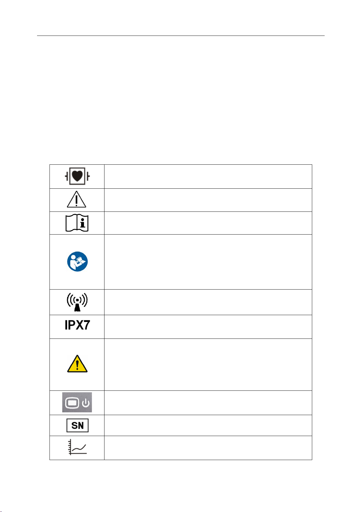
1.3 Explanation of Symbols on the Telemetry transmitter
DEFIBRILLATION-PROOF TYPE CF APPLIED PART
Caution
Operating instructions
Operating instructions
Background color---blue
Symbol color---white
The user manual is printed in black and white.
Non- ionizing electromagnetic radiation
harmful effects: temporary immersion)
General warning sign
Background color---yellow
Symbol and outline color---black
The user manual is printed in black and white.
Power Supply switch
SERIAL NUMBER
Trend
- 6 -
Page 18
Telemetry Transmitter User Manual Intended Use and Safety Guidance
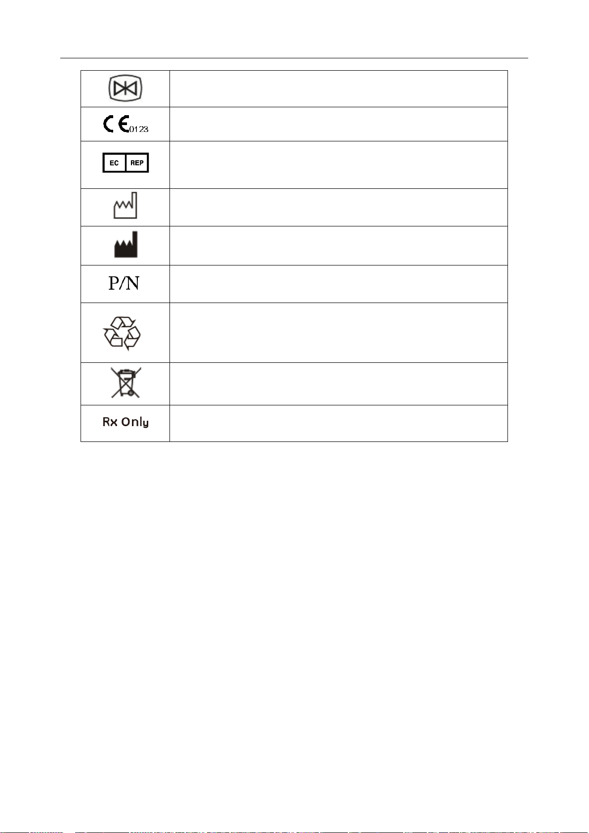
AUTHORISED REPRESENTATIVE IN THE EUROPEAN
Caution: Federal (U.S.) Law restricts this device to sale by or on the
Picture freeze
CE marking
COMMUNITY
Date of manufacture
MANUFACTURER
Part Number
General symbol for recovery/recyclable
Disposal method
order of a physician.
- 7 -
Page 19
Telemetry Transmitter User Manual Overview
70
SpO
2 %
99
HR bpm
RR rpm
14
ST II 0.10
PR bpm
70
PACE
Icon
Bed No.
Networking Icon
Battery Status
Wireless signal Icon
Information
Parameter
Pulse Bar Graph
Chapter 2 Overview
2.1 System Introduction
Telemetry monitoring system can realize an integrated monitoring for multiple mobile patients or
bed patients via wirel ess network. It is eas y for extending and net deploying. Among the system,
telemetry transmitter owns small size, light weight and long battery life and works with
MFM-CMS to form an integrated monitoring solution.
The detailed operation instructions of MFM-CMS refer to Central Monitoring System User
Manual
2.2 Display Screen of Telemetry Transmitter
The display screen of telemetry transmitter is associated with the parameters’ configuration
customer bought.
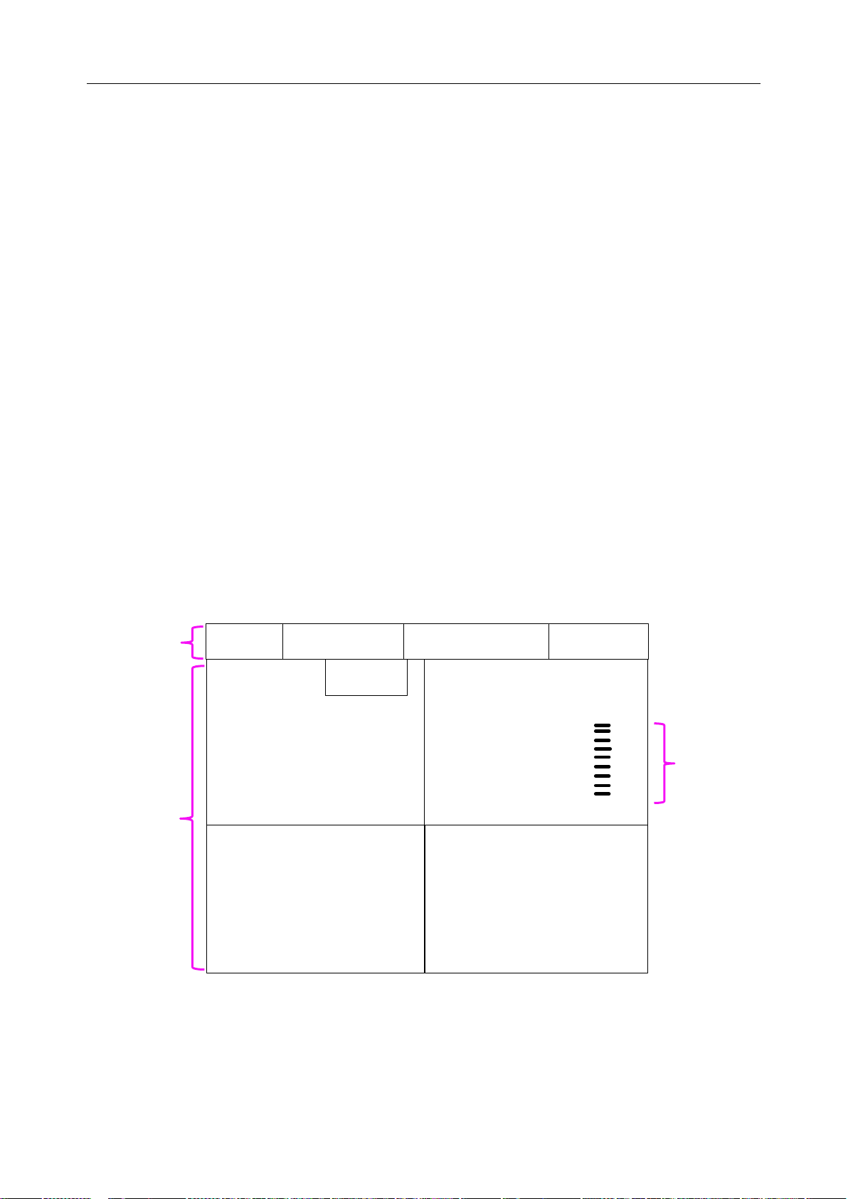
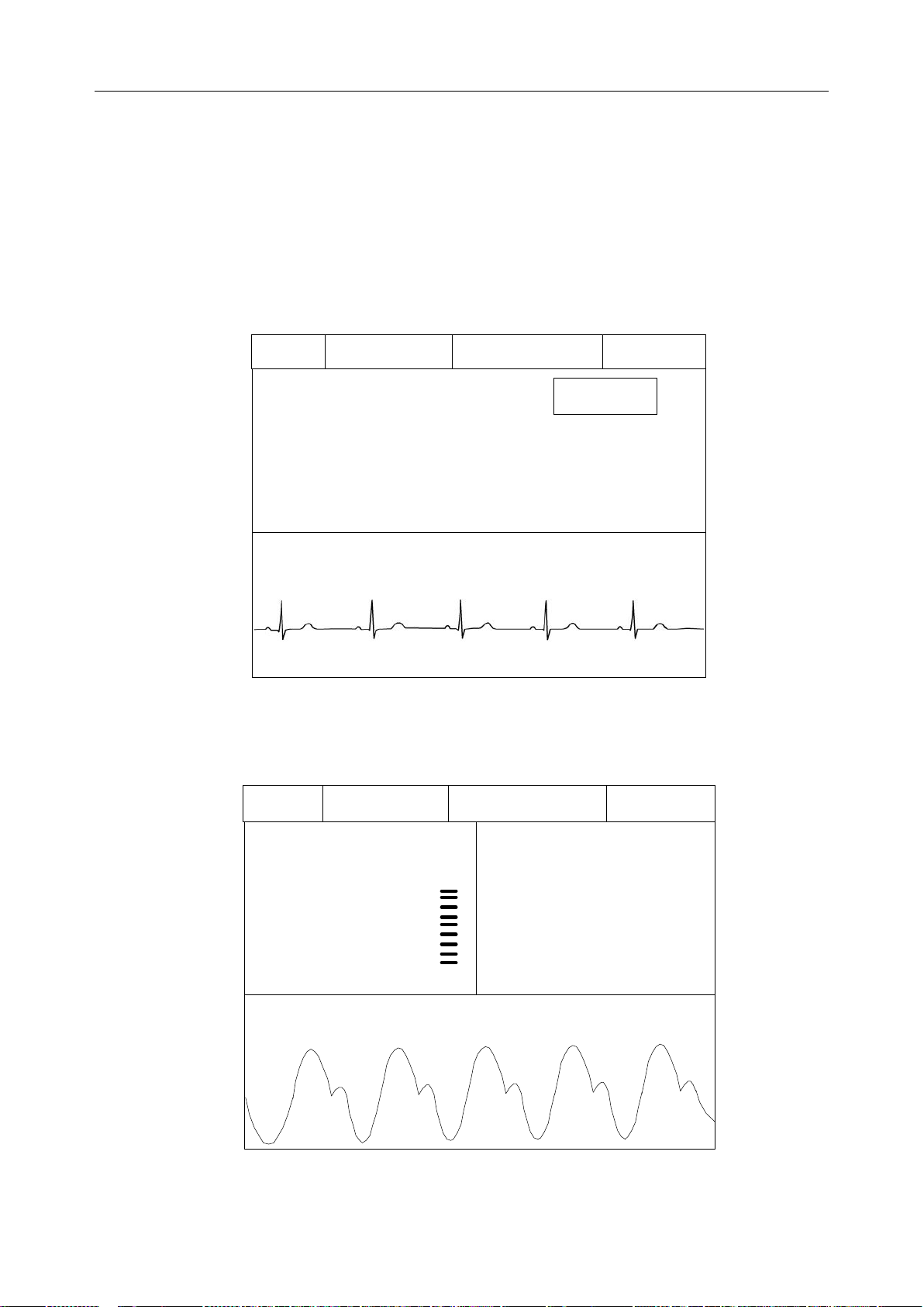
2.2.1 Default Interface
The default interface has two parts: Information Area and Parameter Value Area. Under
parameters on, the symbol ?will be displayed in parameter value area if measuring is not
implemented or the measured value is invalid. The default interface with three parameters on is as
follow:
Area
V alue Area
Figure 2-1 ECG + SpO2 + RESP Default Interface(ST on)
- 8 -
Page 20
Telemetry Transmitter User Manual Overview
60
HR bpm
II
PACE Icon
Bed No.
Networking Icon
Battery Status
Wireless Signal Icon
SpO2 %
99
血氧波
60
HR bpm
Bed No.
Networking Icon
Battery Status
Wireless Signal Icon
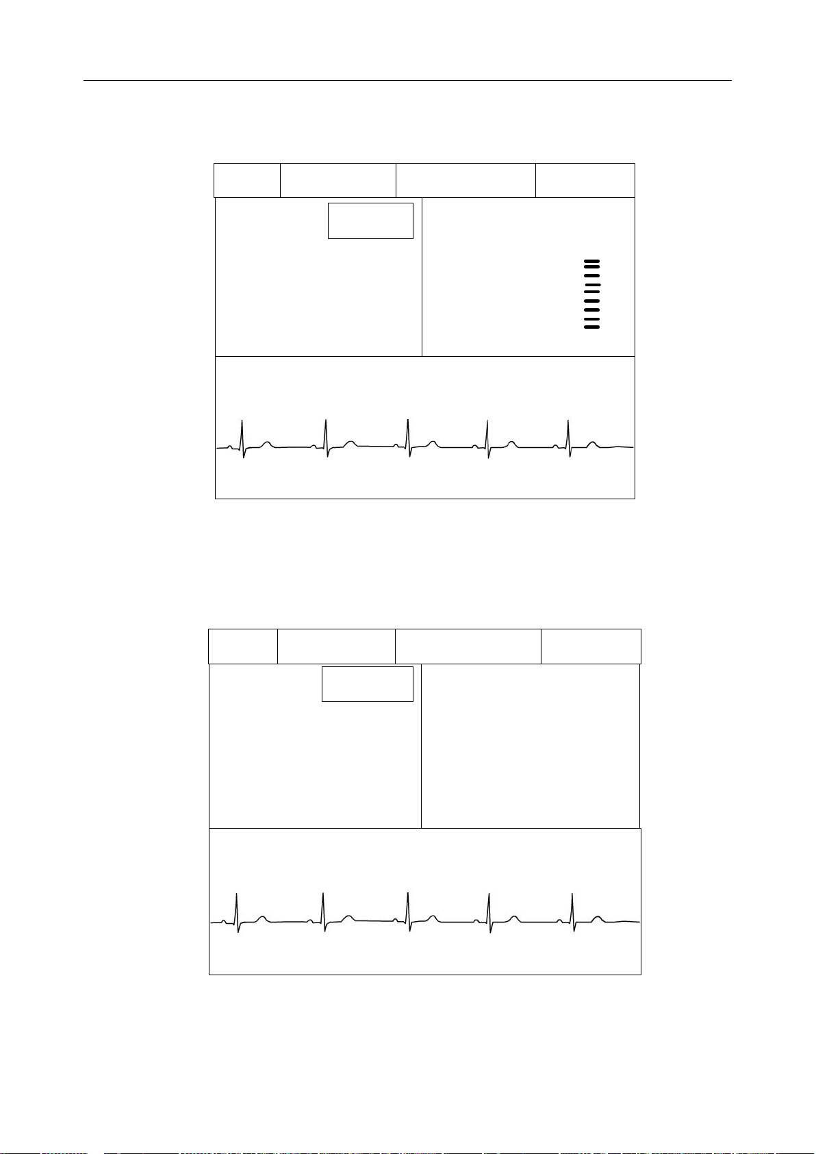
2.2.2 Main Interface
Main interface has two kinds: Value - Waveform Main Interface and Trend Graph Main Interface.
Value - Waveform Main Interface
1. ECG Interface: includes information area, ECG value of calculated lead and corresponding
wave.
Figure 2-2 ECG Interface(ST off)
2. SpO2 Interface: includes information area, SpO2 value, PR value and PLETH wave.
Figure 2-3 SpO 2 & PR Interface
- 9 -
Page 21
Telemetry Transmitter User Manual Overview
60
SpO
2
%
99
HR bpm
II
ST
II
0.10
PACE
Icon
Bed No.
Networking Icon
Battery Status
Wireless Signal Icon
60
RR rpm
14
HR bpm
II
ST
II
0.10
PACE
Icon
Bed No.
Networking Icon
Battery Status
Wireless Signal Icon
3. ECG&SpO2 Interface: includes informat ion area, EC G value of calcu lated lead, SpO2 value
and ECG wave.
Figure 2-4 ECG & S pO2 Interface(ST on)
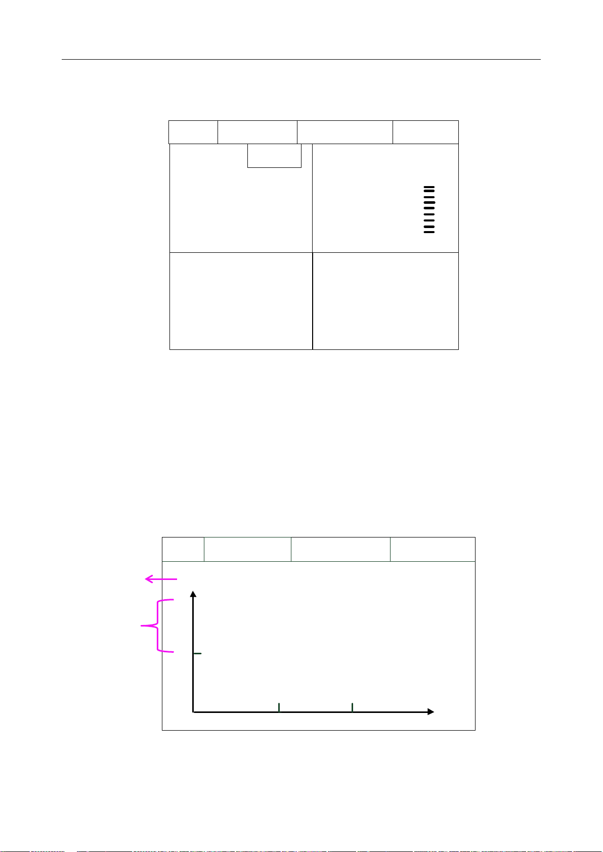
4. ECG&RESP Interface: includes information area, ECG value of calculated lead, RR value
and ECG wave.
Figure 2-5 ECG & RESP Interface(ST ON)
- 10 -
Page 22
Telemetry Transmitter User Manual Overview
70
SpO2 %
99
HR bpm
RR rpm
14
ST
II
0.
10
PR
bpm
70
PACE
Icon
Bed No
.
Networking Icon
Battery Status
Wireless signal Icon
Networking Icon
Bed No
.
Wireless signal Icon
Battery Status
min
XXX
0
xx
-90 -60 -30
xx
Parameter name
and unit
Parameter
5. ECG&SpO2&RESP Interface: includes information area, ECG value of calculated lead,
SpO2 value, PR value and RR value. It’s actually the same with default interface.
Figure 2-6 ECG & SpO2 & PR & RESP Interface(ST ON)
Trend Graph Main Interface
Trend Graph Main Interface can be displayed when parameters are on. It includes current
patient’s data only, not the history patient’s.
According to the parameters customer chosen, trend graph main interface has four kinds: ECG
Trend Graph Main Interface, SpO2 Trend Graph Main Interface, PR Trend Graph Main Interface
and RESP Trend Graph Main Interface.
scale value
Figure 2-7 Trend Graph Main Interface
- 11 -
Page 23
Telemetry Transmitter User Manual Overview
1
2.2.3 Setting Interface
Setting interface includes password inputting interface and function setting interfac e that will be
displayed after confirm pass word. Under non-0-level of bat tery condition, when screen is in the
setting interface, the screen can keep opened till 0 level of battery.
In setting interface, there are functions: choosing demo mode, choosing language of
telemetry transmi tter, checking network configuration, upgrading operation and checking related
information of telemetry transmitter.
WARNING
1. The functions in setting interface, such as checking network configuration and
upgrading operation, are for service personnel only.
2. Demo Mode is for demonstration purposes only. You must not change into Demo
Mode during monitoring. In Demo Mode, all stored trend information is deleted from
the telemetry transmitter’s memory.
NOTE:
Multiple languages are applicable to main interface. Setting interface supports English
only.
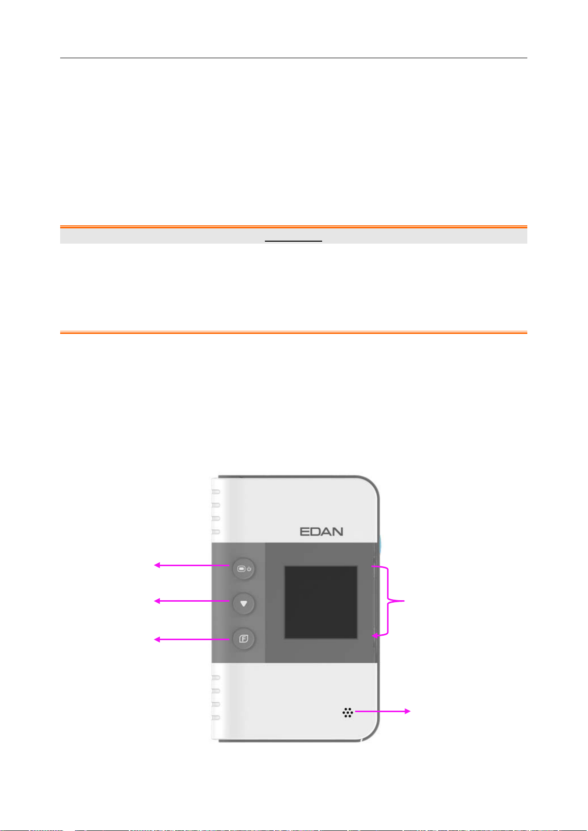
2.3 Appearance of Telemetry Transmitter
2.3.1 Front View
2
3
Front View
- 12 -
Page 24

Telemetry Transmitter User Manual Overview
n, keep pressing at least for 3
press shifting to
Terms explanation
Main Interface, Default Interface and Setting Interface: refer to 2.2 Display Screen of
Telemetry Transmitter.
Control focus: means the position cursor chosen by shifting key.
Focus a cceptance: means user accept the position where the control focus is. It is triggered
by function acceptance key.
1 Power supply switch
Under telemetry transmitter off:
Keep pressing at least for 2 seconds to turn on and the green light on power
supply switch will occur.
Under telemetry transmitter on:
When power is in 0 level or screen is ope
seconds to turn off.
When screen is open, press it to close screen.
Under telemetry transmitter on, when screen is closed with non-0-level of
battery, press is to open screen. (If screen is closed with 0 level of battery,
pressing it cannot open screen, and the screen will keep closed till shutdown).
2 Shifting
In main interface, press it to display between Value - Waveform Main Interface
and Trend Graph Main Interface.
In setting interface, press it to switch control focus.
When input password or choose language: ① press shifting to switch control
focus; ② press function acceptance to accept focus; ③
choose password or language.
In EC G leads connection sketch interface (refer to 4.1.2 Switching On), pr ess
it to make the sketch disappear.
- 13 -
Page 25

Telemetry Transmitter User Manual Overview
to exit focus
Function acceptance
3
In main interface, press it to return to default interface.
In setting interface, after control focus is switched to an icon, press function
acceptance to accept this function.
When input password or choose language: ① press shifting to switch control
focus; ② press function acceptance to accept focus; ③ press shifting to
choose password or language; ④ press function acceptance
acceptance.
1+3 Function group key (press power supply switch and function acceptance
simultaneously at least for 1second)
In main interface or in default interface, press it to display password window.
In DEMO mode, press it to exit demo mode.
4 Display screen
5 Speaker
2.3.2 Rear View
Rear View
Manufacturer’s information is listed on this side. Detailed information pl ease refers to the
actual machine.
- 14 -
Page 26
Telemetry Transmitter User Manual Overview
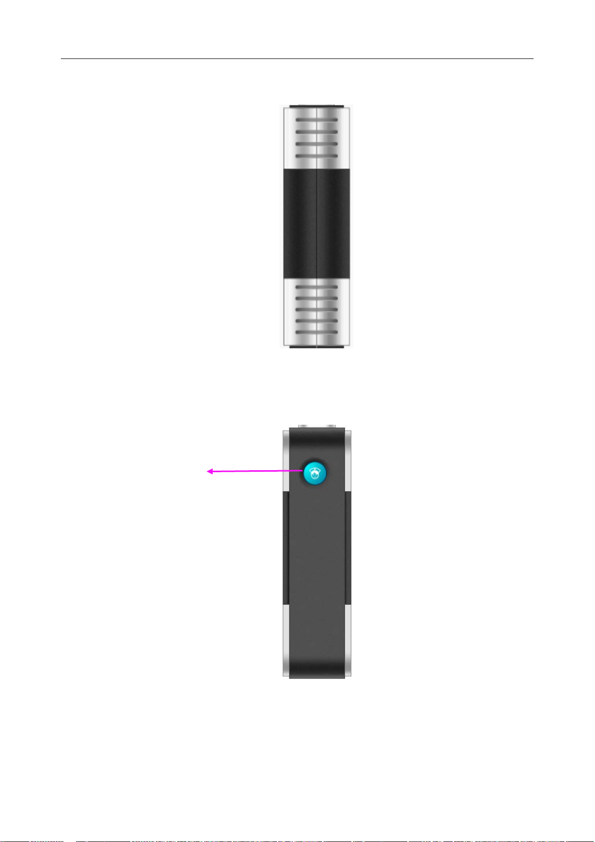
Nurse call key
2.3.3 Left Side View
2.3.4 Right Side View
Left Side View
Right Side View
Nurse call key: press it to display calling nurse information on MFM-CMS.
- 15 -
Page 27
Telemetry Transmitter User Manual Overview
1
2
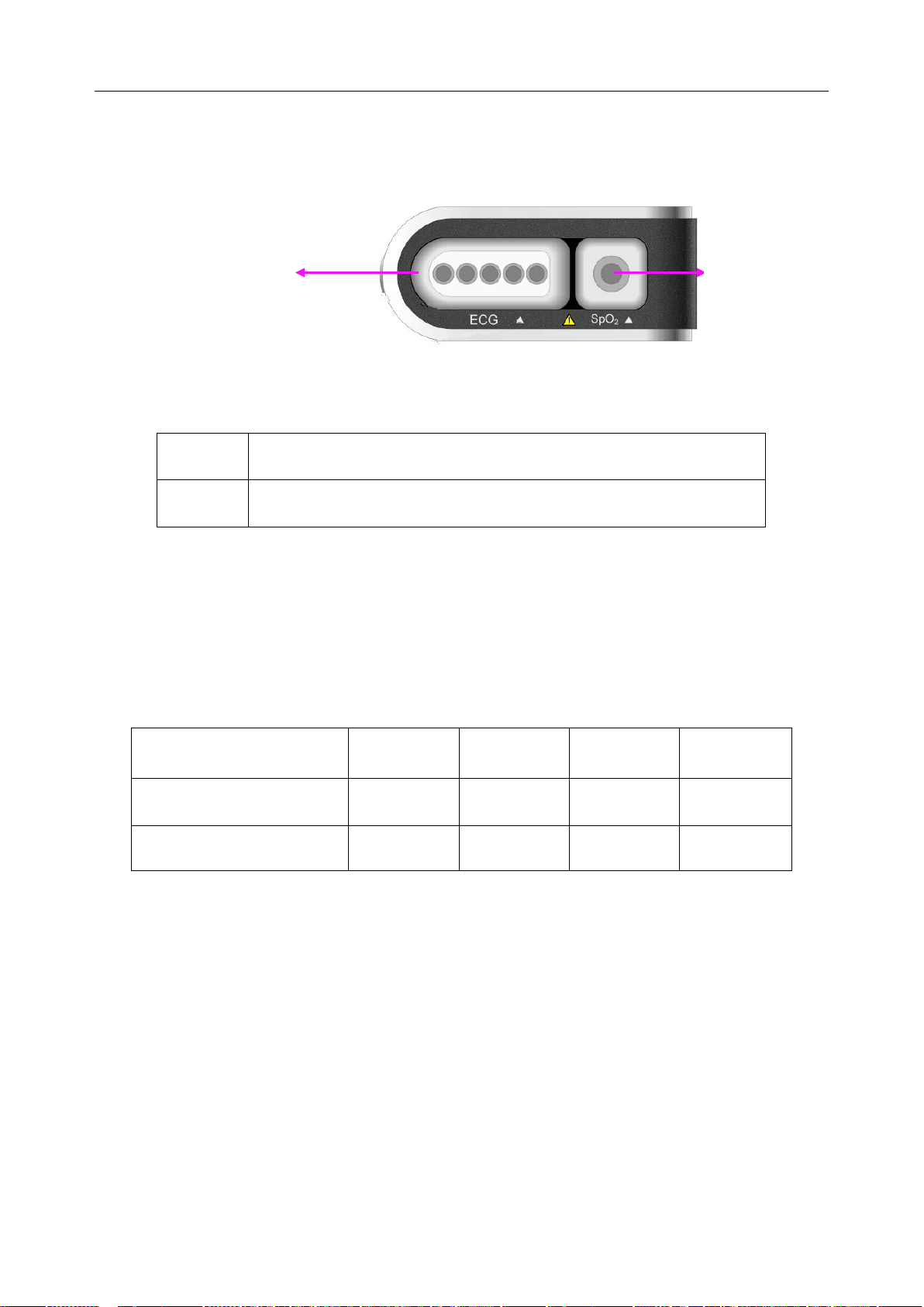
2.3.5 Top View
Top View
1 ECG cable connector
2 SpO2 sensor connector
2.3.6 Bottom View
Refer to 4.1.1 Battery Installing and Replacing Battery Installing and Replacing.
2.4 Configuration
The configuration of telemetry transmitter is listed below:
Function Configuration ECG SPO2 PR RESP
ECG
ECG & SPO2
“√” means the parameter standardly configured is on b y default after telemetry transmitter
switches on. Changing status should be operated on MFM-CMS. The parameter status last
used will be recovered when the device is switched on again.
“○” means the param eter standa rdly configured is off by default after telemetry transmitter
√ × × ○
√ ○ ○ ○
switches on. Changing status should be operated on MFM-CMS. T he parameter status last used
will be recovered when the device is switched on again.
“×” means the parameter is not configured.
NOTE:
The parameters only standardly configured are applicable.
- 16 -
Page 28
Telemetry Transmitter User Manual Overview
xx
x
xx
x
xx xx xx xx
60
99
xx
x
xx
x
xx
xx xx
xx
60
99
xx
x
xx
x
xx xx xx xx
60
99
xx
x
xx
x
xx
xx xx xx
60
99
xx
x
xx
x
xx xx xx xx
60
99
xx
x
xx
x
xx
xx xx
xx
60
99
xx
x
xx
x
xx xx
xx xx
60
99
1
3
2
xxxx
2.5 Display Screens of the MFM-CMS
2.5.1 Overview
The MFM-CMS can display the monitoring data using a single display or using dual displays.
The main screen and t he auxiliary screen are the main op eration screens. The main screen and
auxiliary screen on a single display are different from those on dual displays.
The patient sectors can be displayed in two modes: the general display mode with waveforms and
physiological parameter values displaying on the screen and the large font display mode with
only parameter values displaying on the screen. The number of patient sectors which you can
simultaneously view on the main screen and the size of the patient sectors are depended on the
layout of the patient sectors.
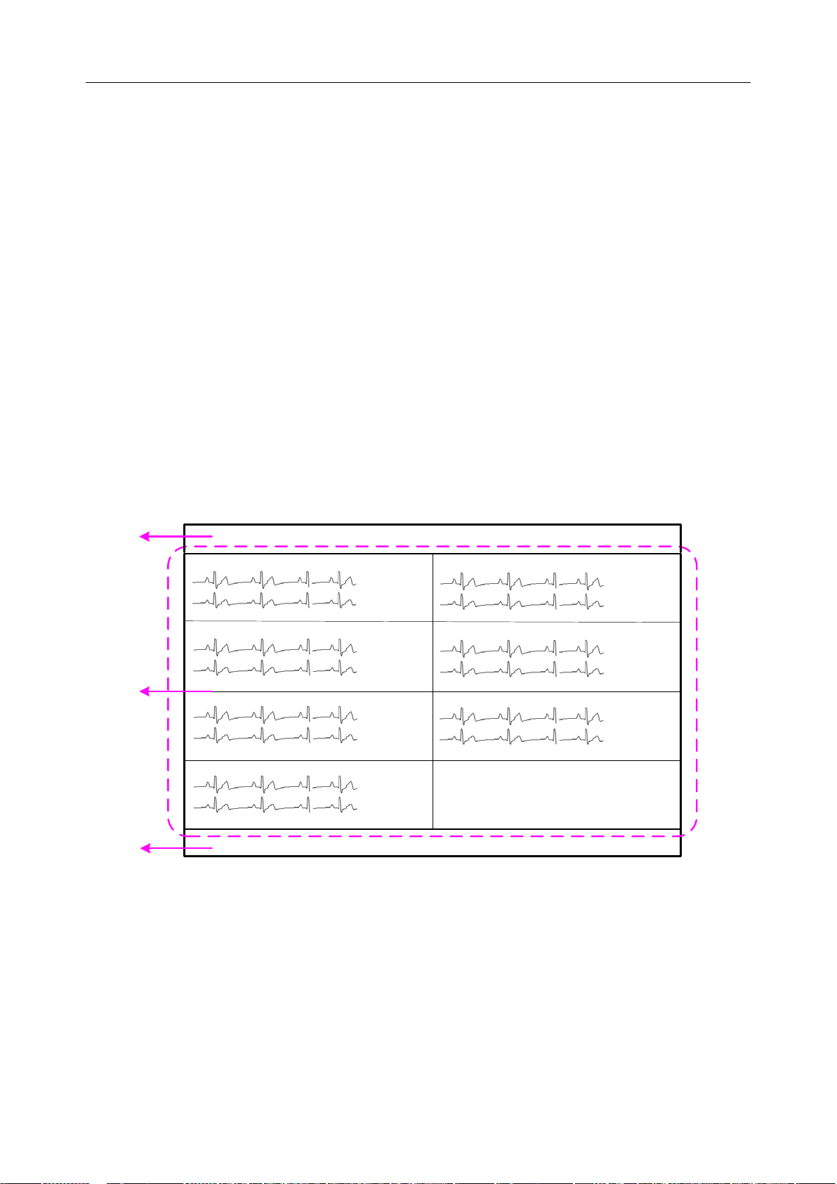
2.5.2 Main Screen
If a single display is used, the MFM-CMS system will enter the main screen for the single display
(shown as Figure 8) after the system starts up. If dual displays are used, it will enter the main
screen for dual displays (shown as Figure 9).
1: System information area 2: Patient sectors 3: Quick control area
Figure
2-8 Main Screen on a Single Display
- 17 -
Page 29
Telemetry Transmitter User Manual Overview
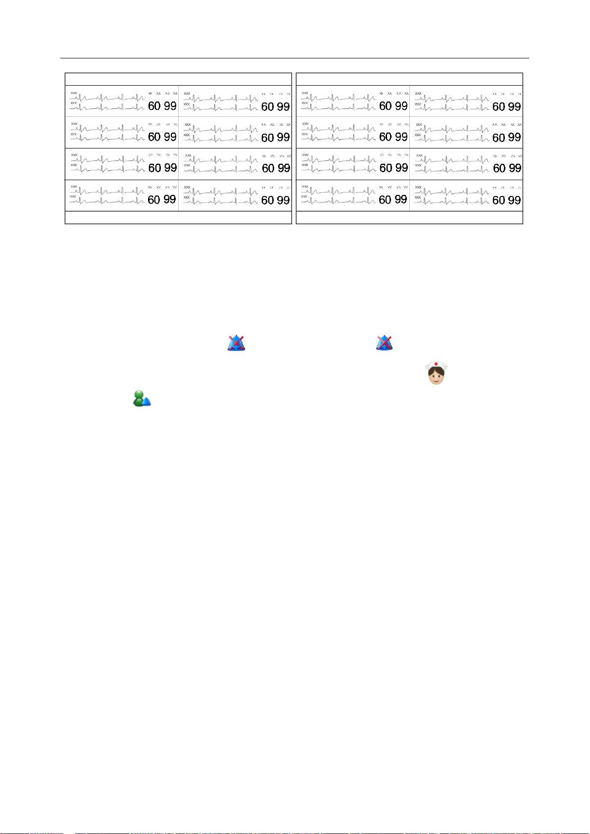
Figure
2-9 Main Screen on Dual Displays
2.5.2.1 System Information Area
The following information will be displayed in this area:
The hospital and department information.
Alarm sound pause indicator and alarm mute indicator .
When connecting with the telemetry transmitters: nurse call indicator and patient call
indicator .
Alarm information and prompts of the MFM-CMS. If more than one piece of message
occurs, they will be displayed circularly. For MFM-CMS system alarms and prompts, please
refer to Appendix II of MFM-CMS Central Monitoring System User Manual.
The system time.
2.5.2.2 Patient Sectors
A patient is monitored by a telemetry transmitter. This telemetry transmitter will occupy a patient
sector when it is connected to the MFM-CMS; meanwhile, the monitoring data will be displayed
in this patient sector. The MFM-CMS supports 64 telemetry transmitters connected to the system;
therefore, a total of 64 patient sectors are available in the MFM-CMS. The layout of patient
sectors may cause some patient sectors temporarily invisible (refer to 2.5.5 Layout of Patient
Sectors).
The patient sector has three types of state:
Network Disconnected: The black background with the white font Disconnected in a patient
sector indicates no patient is admitted or assigned to this patient sector, or the patient
assigned to this sector has been discharged.
Improper Offline: If the system is connected with telemetry transmitter, patient information,
the name of telemetry transmitter, and the message Telemetry No Signal with yellow
background are displayed in the patient sector and accompany with medium level alarm
sound. Improper Offline indicates the patient in this sector has been admitted but is offline.
- 18 -
Page 30
Telemetry Transmitter User Manual Overview
Button
Button Label
Function
Click on this symbol to make the alarm pause and the
to disable the pause function and the
Click on it to enter the review interface, including patient
information review, waveform review, alarm review, trend
Click on it to shut down the MFM-CMS and the operating
System Volume
then enter the password
up window; the entire
appears. To
Networked Monitoring: Display of patient information, waveforms, trend data and alarm
information indicates the patient in this sector has been admitted and is properly networked
and under observation.
Refer to Chapter 6 for more information about the patient sectors in networked monitoring
state.
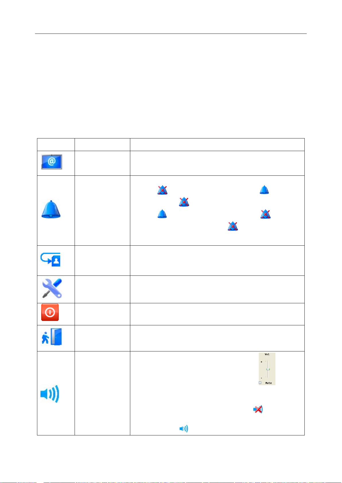
2.5.2.3 Quick Control Area
Function Buttons
The quick control area contains the following function buttons:
Main Screen Click on it to return to the main screen.
symbol appears in place of the symbol . And click
Audio Pause
on the symbol
symbol appears in place of the symbol . When the
alarm sound pauses, the symbol as well as th e related
prompt will be displayed in the system information area.
Review
review.
System Setup Click on it to enter the system setup menu.
Shut Down
system.
Admission Click on it to open the patient admission window.
Click on it, and the volume adjustor icon appears.
Adjustor
Select the Mute check box, and
ABC in the text box on the pop-
system become mute, and the symbol
disable the silence function, tick the Mute ch eck box again
and the symbol appears. Additionally, the user can drag
- 19 -
Page 31

Telemetry Transmitter User Manual Overview
the volume adjustor to your desired volume.
CMS will keep mute as soon as mute check box
is ticked. If a new alarm occurs, the system won’t break
mute status and keep mute until mute check box is
1
2 3
…
…
4
NOTE:
MFM-
ticked again. Please use it with caution.
Networked State
The networked state window has 64 panes (shown as Figure 2-10) representing the 64 telemetry
transmitters that can be supported and connected to the MFM-CMS. The pane only displays the
telemetry transmitter’s number. You can access the single bed interface by clicking on the pane.
Figure
The pane has the several types of state:
Blank: Network disconnected (refer to Section 2.5.2.2 Patient Sectors).
With grey background and white bed number: Improper offline (refer to Section 2.5.2.2
Patient Sectors).
With green background: Networked monitoring (refer to Section 2.5.2.2 Patient Sectors);
without physiological alarm.
With yellow background: Networked monitoring (refer to Section 2.5.2.2 Patient Sectors);
with medium or low level physiological alarm.
With red background: Networked monitoring (refer to Section 2.5.2.2 Patient Sectors); with
high level physiological alarm.
2-10 Networked State
2.5.3 Auxiliary Screen
If the patient sector is in the state either of improper offline or networked monitoring, you can
access the auxil iary scree n by clickin g the wavefo rm area or pa rameter ar ea on t he patient sector.
The auxiliary scr een on a single dis play is s hown as Figure 2-11, and the one on dual displays is
shown as Figure 2-12.
- 20 -
Page 32

Telemetry Transmitter User Manual Overview
3
2
4
1
5
xxx
xx
xx
xx
xx
60
99
xxx
xxx
xx
xx
xx
xx
60
99
xxx
xxx
xx
xx
xx
xx
60
99
xxx
xxx
xx
xx
xx
xx
60
99
xxx
xxx
xx
xx
xx
xx
60
99
xxx
xxx
xx
xx
xx
xx
60
99
xxx
xxx
xx
xx
xx
xx
60
99
xxx
xxx
xx
xx
xx
xx
60
99
xxx
2
1
3
1
3
5
4
Figure
2-11 Auxiliary Screen on a Sin gle Display
1: System information area 2: Patient sectors 3: Switch and setup area for sub-window
4: Sub-window of auxiliary scr een 5: Quick control area
The auxiliary screen contains a group of sub-windows including Single Bed View, Patient
Mgmt, Wave Review, Alarm Review, Trend Review and Parameter/Waveform Setup. The
sub-window of Single Bed View will be displayed by default when you access the auxiliary
screen.
1: System information area 2: Patient sectors 3: Quick control area
3: Switch and setup area for sub-window 4: Sub-window of auxiliary screen
In the switch and setup area for the sub-window, you can:
Figure
2-12 Auxiliary Screen on Dual Displays
Click a tag to switch the current sub-window to another sub-window.
Click to scroll leftward and click to scroll rightward in the tag bar.
- 21 -
Page 33

Telemetry Transmitter User Manual Overview
xxx
xxx
xx xx xx xx
60
99
xxx
xxx
xx xx xx xx
60
99
xxx
xxx
xx xx xx xx
60
99
xxx
xxx
xx
xx xx xx
60
99
xxx
xxx
xx xx xx xx
60
99
xxx
xxx
xx xx xx xx
60
99
2
3
1
4
5
6
7
8
xxx
xxx
xx xx xx xx
60
99
60
99 36
.5 40
xx xx xx xx xx xx xx xx
Click to open the drop-down list in which you can set the tags to show/hide.
Click to exit the auxiliary screen and enter the main screen.
Drag a tag to adjust its location.
Click or to switch between full screen display mode and half screen display
mode for the auxiliary screen when using a single display.
2.5.4 Large Font D i spl ay
Choose Display the window in large font from the menu in the patient sector (refer to Section
6.3 Menu in the Patient Sector), and this sector will be displayed in the large font display mode
shown as Figure 2-13. Choose Display th e window in large font again, and the sector will be
displayed in the general display mode. In the large font display mode, parameter values are
displayed in the patient sector, but no waveform is shown.
Figure
1: Large font display mode 2-8: General Display Mode
2-13 Viewing One Patient Sector in Large Font Display Mode
Choose Display all windows in large font from the menu in the patient sector, and all sectors
will be displayed in the large font display mode shown as Figure 2-14 Choose Display all
windows in large font again, and all sectors will be displayed in the general display mode.
- 22 -
Page 34

Telemetry Transmitter User Manual Overview
60
99 36.5 40
xx xx xx xx xx xx xx xx
60
99 36
.
5 40
xx xx xx xx xx xx xx xx
60
99 36.5 40
xx xx xx xx xx xx xx xx
60
99 36.5 40
xx xx xx xx xx xx xx xx
60
99
36
.5 40
xx xx xx xx xx xx
xx
xx
60
99 36.5 40
xx
xx xx xx xx xx xx xx
60
99 36.5 40
xx
xx
xx xx xx xx xx xx
60
99 36.5 40
xx xx
xx
xx xx xx xx xx
Figure
2.5.5 Layout of Patient Sectors
The number of patients you can view on the screen and the size of each patient sector depend on
the layout of the patient sectors. If 64 telemetry transmitters are connected to the MFM-CMS and
the number of patient sectors displayed on the main screen is set to 32, the screen will only
display 32 patient sectors and the other 32 sectors are invisible. You may:
Switch between the visible and invisible patient sectors (refer to Section 5.3 Switching
Patient sector).
Click bed number to view the 64 patient sectors in the networked state window (refer to
Section 2.5.2.3 Quick Control Area).
Refer to Section 10.1.2 Display Setup for mor e information about setting the layout of the patient
sectors.
2-14 Viewing All Patient Sectors in Large Font Display Mode
- 23 -
Page 35

Telemetry Transmitter User Manual Installat ion o f telemetry monitoring syst em
Chapter 3 Installation of Telemetry Monitoring System
NOTE:
1. The entire system must be specified by the personnel authorized by EDAN.
2. To ensure that the system w orks pr operly, please read the user manual and follow the
steps before using .
3.1 Initial Inspection
Before unpacking, check the packaging and ensure that there are no signs of mishandling or
damage. If the ship ping cartons are damaged, co ntact the carrier for comp ensation and package
them again.
Open the package carefully and remove telemetry transmitter, MFM-CMS and accessories.
Check that the contents are complete and that the correct options and accessories have been
delivered.
If you have any question, please contact your local supplier.
3.2 Installation Environment
System working environment should be in consistent with the requirements in this user manual
(refer to A.2.2 Environmental Specifications).
System working should avoid noise, shock environment and the environment where the
concentrations of flammab le anest het ics or o ther explosive materials ma y occur. The surrounding
of device should have enough space (at least 5 cm) to maintain and transfer heat.
NOTE:
1. Please keep the system away from radio transmitters and high power electrical and
mechanical device for those could affect monitoring.
2. Wireless transmission is applicable to the system. It’s normal that irregular waveform
due to outside interference may occur. If you have any question on Electromagnetic
environment, please contact service personnel.
3.3 Power Supply Requirement
Power supply should be in consistent with the requirements in this user manual (refer to A.2.4
Battery).
NOTE:
1 Connect the power cable of MFM-CMS to the socket specialized for hospital use.
2 Only use the power cable supplied by EDAN.
- 24 -
Page 36

Telemetry Transmitter User Manual Installat ion o f telemetry monitoring syst em
3.4 Wireless Network
Telemetry translator and MFM-CMS construct wireless network through AP. The qualified
engineers specified by EDAN are responsible for installing wireless network and performance
tests. For details, please refer to Patient Monitor Wireless Network Installation Guide.
NOTE:
1. Be awar e that some networ k-based functions may be l imi t ed for telemetry transmitter
on wireless networks in comparison with those on wired networks.
2. The obstacle may interfere with data transmission and even cause data loss.
3. When telemetry transmitter has been connected to a wireless network, to make the
change of the Bed No. effective, you need to disconnect the wireless connection and
then connect it again or reboot telemetry transmitter.
3.5 Installation Method
The personnel specified by EDAN are responsible for system installation, which includes
surrounding verification, MFM-CMS installation, wireless device installation and telemetry
transmitter installation, etc.
WARNING
1. When the system is required to connected with other electric devices, and those
electric devices are not approved to be safe for connection with the system, such as
current leakage may cause electronic shock, please contact specialists in hospital or
our service personnel.
2. Upgrade operation is only for personnel authorized by EDAN.
3. Plugging three-pin into two-pin adaptor is prohibited.
4. To change installation environment or move system to another site, please contact
our service personnel.
5. The medic al elec tric al equi pment ne eds to be installed and put i nto service acc ordi ng
to the EMC Information provided in this user manual.
CAUTION
1. To avoid unpredictable results from sudden power interruption, please provide UPS
(Uninterruptible power supplies) for the system.
2. Keeping battery bin dry is required.
- 25 -
Page 37

Telemetry Transmitter User Manual Installat ion o f telemetry monitoring syst em
NOTE:
Crossover Ethernet cable is connected with computer and parallel Ethernet cable is
connected with HUB.
3.6 Checking the Printer
If an ext ernal printer is required, please confirm the printer is powered on and paper is properly
installed in the slot. If it is not powered on or no paper exists, please power the printer on
according to power requirements in MFM-CMS C entral Monitoring System User Manual and put
appropriate paper.
WARNING
External device connected with system, such as printer or speaker, should be in
accordance with power requirements for system.
3.7 Checking the Telemetry Monitoring System
Make sure there is no damage on the measurement accessories and cables. Then turn on the
telemetry and MFM-CMS, ch eck whether the system can start normal ly. Make sure batter y for
telemetry transmitter has enough power, MFM-CMS can alarm no rmally and the alarm sound is
heard.
WARNING
If any signs of da ma ge are detected, or screen displays error messages, do not use it on
any patient. Contact service center immediately.
NOTE:
1 Check all functions applicable and make sure that the system is in good status.
2 If telemetry transmitter is in low battery power status (0 level), replace battery to
ensure the electric power is enough.
3.8 Setting Date and Time
Setting and displaying date and time is applicable to MFM-CMS only.
The user can set the corr ect date and time and their desired form at. There are thre e kinds of date
format: yyyy-MM-dd, dd-MM-yyyy, MM-dd-yyyy, two kinds of time format: HH-mm-ss (24
hours) and hh-mm-ss tt (12 hours), and three date separator: /, - and. To change the date and tim e
setup, please sel ect Main Screen > Sys tem Setup > Common Setu p > Date /Time Setup, and
select the desired settings from the right menu. The time and date displayed on the main screen
will also change after change the date and time setup and their format.
- 26 -
Page 38

Telemetry Transmitter User Manual Installat ion o f telemetry monitoring syst em
WARNING
During patient monitoring, a change in date and time will influence the storage of trend
data.
NOTE:
1 The user must restart MFM-CMS to make the change effective.
2 If the system is not used for a longer period of time, its system time may be
inaccurate. In this case, reset the system time after powering on.
3 If the system time cannot be saved and resumes the default value after restart,
contact the service department of EDAN.
3.9 Handing Over the Central Monitoring Systerm
If you are handing over system to the end-users directly after installation and configuration, make
sure that it is in the monitoring mode.
The users must b e adequately trained to use the system before monit oring a patient. To achieve
this, they should have access to, and read, the following documentation delivered with system:
User Manual (this book) - for full operating instructions.
Quick Reference Card - for quick reminders during use.
3.10 FCC Statement
This equipment has been tested and found to comply with the limits for a Class B digital device,
pursuant to part 15 of FCC Rules. These limits are designed to provide reasonable protection
against harmful interference in a residential installation. This equipment generates and can radiate
radio frequency energy and, if not installed and used in accordance with the instructions, may
cause harmful interference to radio communications. However, there is no guarantee that
interference will not occur in a particular installation. If this equipment does cause harmful
interference to radio or television reception, which can be determined by turning the equipment
off and on, the user is encouraged to try to correct the interference by one or more of the
following measures:
1. Reorient or relocate the receiving antenna.
2. Increase the separation between the equipment and receiver.
3. Connect the equipment into an outlet on a circuit different from that to which the receiver is
connected.
4. Consult the dealer or an experienced radio/TV technician for help.
This device complies with Part 15 of FCC Rules.
Operation is subject to the following two conditions:
- 27 -
Page 39

Telemetry Transmitter User Manual Installat ion o f telemetry monitoring syst em
1. This device may not cause harmful interference, and
2. This device must accept any interference received, including interference that may cause
undesired operation.
NOTE:
The manufacturer is not responsible for any radio or TV interference caused by
unauthorized modifications to this equipment. Such modifications could void the user’s
authority to oper ate t his equipment.
- 28 -
Page 40

Telemetry Transmitter User Manual Basic Operations
Battery compartment latch
Green bar occurs under
Red bar occurs under
Chapter 4 Basic Operations
The general functions for telemetry transmitter are operated on MFM-CMS, which include
chapter 5 patient management, chapter 6 patient sector, chapter 7 viewing single bed, chapter 8
setting telemetry transmitter via MFM-CMS, chapter 9 review, chapter 10 system setup, chapter
11 alarm management, chapter 12 alarm information, chapter 13 printing, and chapter 14
database management.
The following introduction is about the basic operations for telemetry transmitter and
MFM-CMS.
4.1 Basic Operations for Telemetry Transmitter
4.1.1 Battery Installing and Replacing
locked status.
unlocked status.
Bottom View
Installing:
As pictured above, move the battery compartment latch right t o op en batter y door. Install two AA
alkaline batteries following “+” or “-” indication, and then press the door to close correctly with
“ka-ka” sound.
Replacing:
Method is the same with installing.
Under the condition that telemetry transmitter continuously works at least for 15 minutes and
moreover it has a good Wi-Fi communication (typical network environment with no interference),
the telemetry transmitter can keep power on up to 20 seconds after taking batteries out.
- 29 -
Page 41

Telemetry Transmitter User Manual Basic Operations
WARNING
It is prohibited for patient to install or replac e bat t er y.
4.1.2 Switching On
Under switch off condition, keep p ressing power supply switch at least for 2 seconds to turn on.
Then the green light on power supply switch will occur. At the same time, the following self-tests
will be carried out:
Read parameters configuration. Refer to 2.4 Configuration for configuration information;
Check ECG accessory compatibility.
When accesso ry is not compatible, the screen will display “Check the ECG accessories”; When
compatible and ECG module is active, telemetry transmitter will check ECG leads connection.
The screen will enter into main interface under condition of correct leads connection. Under leads
off or wrong connection, the screen will display ECG leads connect ion sketch in which wrong
leads position and correct leads position will be indicated. ECG leads connection sketch will
disappear in these conditions, leads connection restoring normally, pressin g shifting key or over
60 seconds.
Read automatically ECG leads type (3-lead or 5-lead) and ECG leads style (AHA or IEC).
NOTE:
During switch on, user should confirm the green light on power supply switch occurs and
screen displays normally. Nurse call and patient call sounds should also be tested
normally. Refer to 5.7 Nurse Call / Patient Call for more nurse call and patient call
information.
4.1.3 Switching Off
Under telemetry transmitter on:
When power is in 0 level or screen is open, keep pressing at least for 3 seconds to turn off..
4.1.4 Open/ Close Scree n
Under telemetry transmitter on, when screen is closed with non-0-level of battery, press is to
open screen. The screen will be back to the interface last used aft e r opening again.
Under screen open condition, do one of the following method to close:
1. Press power supply switch;
2. Without any actions in 15 seconds, screen will close automatically.
After closing, monitoring and net connection keep working normally.
- 30 -
Page 42

Telemetry Transmitter User Manual Basic Operations
Nurse Call Key
Lock Button
4.1.5 Leather Cover Wearing
Telemetry transmitter supports leather cover to wear, as pictured below:
WARNING
To avoid infection or other severe results, leather cover must not touch injured skin.
4.1.6 Nurse Call
Press nurse call key on the right side. Information about nurse call will be sent to
MFM-CMS on which a nurse call symbol will be displayed to tell nurse patient’s calling.
(Refer to 5.7 Nurse Call / Patient Call)
4.2 Basic Operations for MFM-CMS
4.2.1 Mouse Operation
Usually, we use the following terms to describe mouse operation:
Left-key:
1. Click: move mouse to the target, then quickly press left-key once and release it.
2. Double-click: move mouse to the target, then quickly press left-key twice and release it.
3. Drag: move mouse to the target, press left-key and move to the destination and then release
Right-key:
it.
- 31 -
Page 43

Telemetry Transmitter User Manual Basic Operations
1. Click: move mouse to the target, then quickly press right-key once and release it.
2. Double-click: move mouse to the target, then quickly press right-key twice and release it.
4.2.2 Switching on/off the MFM-CMS
Starting monitoring
NOTE:
Before starting the system, please verify that the dongle has been installed. Otherwise,
you may fail to access the sys tem .
When all of its components are correctly connected, press the power button on the front panel of
the device. The power indicator on the front panel lights up and the devi ce performs hardware
self-test. If the devi ce works normally, the main screen appears . If the device detects abn ormity
during self-test, it beeps to show alarm and displays error inform ation on the scr een. In this cas e,
you should record the error information, shut down the device and contact technical
representative of E DAN. After the system self-test is completed, you will access the M FM-CMS
system interface and the system will also finish the environment self-test automatically.
Meanwhile, the system will sound Do-Do-Do, a test sound. The user should set the volume
system and confirm that the volume of the system can be heard clearly.
CAUTION
1 Ensure that the sound equipment is always in a state of acti v at ion.
2 The audio adapter and network adapter should be correctly installed, or you may not
access the MFM-CMS.
NOTE:
Ensure that the MFM-CMS system can give the test sound after startup.
Shutting down the System
It is important to shut down the system properly. Follow this simple procedure to properly shut
down your system. This prevents inadvertent errors from occurring during system shut down.
The MFM-CMS can work continuously for a long time. You do not need to shut it down in order
to achieve a longer working life.
You should follow the procedure to shut down the MFM-CMS.
Method 1:
Select Shut Down on the main menu and enter the password ABC. Confirm the password by
clicking OK, and the MFM-CMS as well as the operating system will be shut down.
- 32 -
Page 44

Telemetry Transmitter User Manual Basic Operations
Method 2:
Select System Setup > User Maintain, and enter the password ABC; select Other Setup.
Select Shut Down: the MFM-CMS as well as the operating system will be shut down.
Select Return to Windows: you will exit from MFM-CMS, but the operating system will
not be shut down.
WARNING
1 Shut down the system by strictly observing the shutdown procedure to avoid serious
result.
2 Although UPS is an optional configuration of this system, if you really force to turn off
the UPS, it results in system failure and hence affects the operation of next time.
3 If power cut-off occurs, turn off the system before the UPS exhausts its electricity.
CAUTION
Hospitals without a stable power source should use a UPS to provide power to the
MFM-CMS. The UPS must not be turned off. When there is a power failure, the system
should be shut down by following the specified shutdown procedure before the UPS is
exhausted. If the system has a sudden power failure, system failure may occur and
consequently the system may not work correctly next time or even has a serious result.
NOTE:
If you forget the password, please contact the technical representative of EDAN.
- 33 -
Page 45

Telemetry Transmitter User Manual Patient M anagement
Chapter 5 Pati ent Management
The contents related to this chapter are all operated on MFM-CMS.
5.1 Admitting a Patient
Once MFM-CMS starts up and telemetry transmitter is prop erly connected with MFM-CMS, the
system will prompt the user to admit patients by displaying the number of pending patients at the
information area.
Click Admission in the quick control area to display a window of Pending patient list. Select
the patients you want to admit from the left list in the window, and enter the patient information
in the right area of the window. Click the Admission button at the bottom of the window to
complete patient admission.
After being admitted, a patient will occupy a patient sector. The MFM-CMS displays the
real-time monitoring data which will also be stored in the database.
For the telemetry transmitter that has been offline due to network problems and is networked with
MFM-CMS later, you need not readmit the patient of this telemetry transmitter. This telemetry
transmitter will be automatically online in the patient sector which it has occupied.
WARNING
For telemetry transmitters that have been networked with MFM-CMS for the first time,
you have to complete patient admission by using the methods mentioned above, which
enables the telemetry transmitters to be online and observed by MFM-CMS. Otherwise,
the telemetry transmitters will not be online on MFM-CMS, and the monitoring data will
not be saved by MFM-CMS.
5.2 Changing Patient Information
You can change the patient information on MFM-CMS when you find the information incorrect.
To modi fy the patient information, choose Single Bed View > Patient Mgmt, ent er the correct
information in the appropriate fields and click Update Monitor.
In the patient management window, the user can modify the patient information, such as Serial
No., Patient Name, Type, Gender, Bed No., Date of Birth and so on. After editing the
information, click on the Update Monitor button to update the changes. The patient information
can be printed when the user click on Print.
NOTE:
If you have changed the patient type via the MFM-CMS, the patient type on the telemetry
transmitter will be changed accordingly.
- 34 -
Page 46

Telemetry Transmitter User Manual Patient M anagement
5.3 Switching Patient sector
For a disconnected patient sector (refer to Section 2.5.2.2 Patient Sectors), click an ywhere in
it and choose a patient to be assigned to this section from the patient list.
For a p atient sector which is either improper offline or networked (refer to Section 2.5.2.2
Patient Sectors), select Show from the list on the patient sector (refer to Sector 6.3 Menu in
the Patient Sector), and choose another telemetry transmitter from the patient list; the chosen
telemetry transmitter will be displayed in this patient sector.
5.4 Discharging a Patient
When the monitoring on a patient is completed, you need to discharge this patient by any of the
following methods:
Choose Discharge from the menu in the patient sector (refer to Section 6.3 Menu in the
Patient Sector).
Choose Patient Mgmt > Discharge on the auxiliary screen.
Discharge the patient via the Review window. Refer to Section 9.1.1 Patient Review.
The operation of discharging a patient will cause the patient offline from the MFM-CMS, and
there will be no patient admitted in the related patient sector. The discharged patient will be
shown in the history patient list. Refer to Section 9.1.2 History Patient Review.
5.5 Transferring a Patient
Select Patient Mg mt >Transfer on the auxiliary screen, and you will see a list of online patients.
From this list, select a patient whose bed will be considered as the destination bed and click OK,
and then the current patient will be transferred to the destination bed.
NOTE:
Transferring a patient to the destination bed wi ll at the same time discharge the selected
patient on the destinat ion bed.
5.6 Monitoring Statistics
The monitoring statistics of the selected patients will be shown in the patient management
window. The monitoring statistics covers th e total monitoring time for waveforms and trends, the
number of alarm events.
Click Analysis, the system will:
Analyze the number of high and low limit alarms for each physiological parameter and
analyze the percentage of the limit alarms of the parameter in all limit alarms.
Analyze the number of arrhythmia events for each type of arrhythmia and analyze the
percentage of a certain type of arrhythmia.
Analyze the average value, maximum/minimum value, and measure time of the
maximum/minimum value for the trend values.
- 35 -
Page 47

Telemetry Transmitter User Manual Patient M anagement
5.7 Nurse Call / Patient Call
For the telemetr y transmitter connected to netw ork, you can use the functions of nurse call and
patient call.
The MFM-CMS will response to the nurse call with a sound “du” once the patien t presses the
nurse call button on the telemetry transmitter.
The nurse call ind icator will be displayed in the system information area on the main
screen. You can cancel nurse call by clicking the indicator.
The nurse call symbol will appear in the patient sector and cover the waveforms. You
can cancel nurse call by clicking the symbol.
The nurse call indicator will be displayed in the indicator area in the single bed
window.
The nurse call tune will sound.
Telemetry transmitter will give a sound “du-du-du” when patient call is triggered. Patient Call
Symbol will also appear in the system information area on the main screen. You can
perform or cancel the patient call via the MFM-CMS as follows:
Choose Call Patients from the menu in the patient sector (refer to Section 6.3 Menu in the
Patient Sector) to trigger, and choose Cancel Patient Calling to cancel.
Select the tag Patient Mgmt of auxiliary screen and access the Patient Mgmt window.
Click Call Patients in this window to trigger and click Cancel Patient Calling to cancel.
After calling patients, you can also click Patient Call Symbol in the system information
area on the main screen to cancel.
- 36 -
Page 48

Telemetry Transmitter User Manual Patient Sector
xxx
xxx
xxx
xxx
60
99
36.5 40
xx xx
xx xx
xx
xx xx xx
3
1
2
4 5
xxx
xxx
xxx
Chapter 6 Patient Sector
The contents related to this chapter are all operated on MFM-CMS.
6.1 Overview
Refer to Section 2.5.2.2 Patient Sectors for inform ation about the three types of state of the patient
sector. Refer to Section 2.5.4 Large Font Display for information about the large font display
mode in the patient sect or. Refer to Section 2.5.2 Main Screen for information about the layout of
patient sectors.
When the patient sector is in the improper offline state or in the networked monitoring state, you
can open a menu by clicking on the patient information area. Refer to Section 6.3 Menu in the
Patient Sector for more information about the menu.
When the patient sector is in the improper offline state or in the networked monitoring state, you
can access the auxil iary screen by clicki ng on the wavefo rm area or par ameter area in t he patient
sector.
When the patient sector is in the disconnected state, you can switch between patien t sectors by
clicking on the patient sector. Refer to Section 5.3 Switching Patient sector for more information.
6.2 Networked Monitoring Display
The display of patient sector which is networked is shown as Figure 6-1.
Figure 6-1 Display of the Networked Patient Sector
1: Wavefor m area 2: Parameter area 3: Patient information area
4: Technical alarm/ Prompts/ indicator area 5: Physiological alarm area
Wav eform area and parameter area: It disp lays som e of real-time monitoring waveforms and
parameter values. Refer to Section 6.4 Parameter / Waveform Setup.
Patient information area: It displays the bed number, device name and patient name.
Technical alarm/ Prompts/ Indicator area: It displays the technical alarm messages when a
technical alarm occurs (refer to Section 11.1.2 Technical Alarms). Click on the technical
alarm message, and the list for the current technical alarms will be displayed. When no
technical alarms and no prompts occur, it displays the indicators (shown as Table 6-)
- 37 -
Page 49

Telemetry Transmitter User Manual Patient Sector
Battery power of the telemeter transmitter:
Battery power of the telemeter transmitter:
Battery power of the telemeter transmitter:
Battery power of the telemeter transmitter:
Battery power of the telemeter transmitter:
Wi-Fi signal intensity of the telemeter
Wi-Fi signal intensity of the telemeter
Wi-Fi signal intensity of the telemeter
Wi-Fi signal intensity of the telemeter
indicating the state of the telemetry transmitters.
Indicator Description
Pace on
Pace off
Level 4
Level 3
Level 2
Level 1
Level 0
transmitter: Level 4
transmitter: Level 3
transmitter: Level 2
Table 6-2 Telemetry Trans mitters State I ndicators
transmitter: Level 1
Physiological alarm area: It displays the physiological alarm messages (refer to Section
11.1.1 Physiological Alarms). Click on the physiological alarm message, and the list for the
current physiological alarms will be displayed.
CAUTION
1 Due to the delay of net w ork transmi ssion, t he w aveform v iew ed at th e MF M-CM S has
a delay of 5 seconds compared with the waveform generated at the corresponding
telemetry transmitter.
2 Due to the operating sy stem sched ule, th e wav efor m scan of the M FM-CM S might be
suspended for about 20 milliseconds in very few occasions. After the suspension,
waveform scan will go back to normal status. The quality of patient monitoring during
the suspension will not be affected.
- 38 -
Page 50

Telemetry Transmitter User Manual Patient Sector
6.3 Menu in the Patient Sector
When the patient sector is in the improper offline state or in the networked monitoring state, you
can open a menu by clicking on the patient information area. The available items in this menu
are:
Display the window in large font: Switch between the large font display mode and the
general display mode for the current patient sector. Refer to Section 2.5.4 Large Font
Display.
Display all windows in large font: Switch between the large font display mode and the
general display mode for all patient sectors. Refer to Section 2.5.4 Large Font Display.
Parameter/Waveform Setup: Switch to the Parameter/Waveform Setup window on the
auxiliary screen. Refer to Section 6.4 Parameter/ W aveform Setup.
Monitor Parameter Setup : Switch to telemetry transmitter Parameter Setup window on the
auxiliary screen. Refer to Section 8.2 Setting Parameters.
Discharge: Discharge the patient in the current patient sector. Refer to Section 5.4
Discharging a Patient.
Freeze: Freeze/ unfreeze the waveform in the current patient sector. Refer to Section 6.5
Freeze.
Print: Print the monitoring data in the current patient sector. Refer to Section 6.6 Real-Time
Printing.
Call Patients: Nurse calls patient. Refer to Section 5.7 Nurse Call / Patient Call.
Show: Switch between patient sectors. Refer to Section 5.3 Switching Patient sector.
Alarm Reset: Activate alarm reset function. Refer to Section 6.7 Alarm Reset.
6.4 Parameter/ Waveform Setup
Due to the limited display space of the patient sector, the numbers of wav eforms and paramet ers
to be displayed depends on the numbers of telemetry transmitters displayed on patient sector
which can be set by users (refer to 10.1.2 Display Setup). 6 waveforms and 4 parameters to be
displayed on patient sector are the maximum. You can set the displayed waveforms and
parameters by setting configuration in the Parameter/Waveform Setup window. You may
access this window by either of the two methods below:
Choose Parameter/ Waveform Setup from the menu on the patient sector.
Click the tag Parameter/ Waveform Setup on the auxiliary screen.
6.4.1 Setting Waveforms
Select or deselect the check box before a Wave Name to display or not display the waveform.
Click Update Wave Setup to confirm the configuration. The patient sector will only display the
selected waveforms.
Choose Speed and set th e desired sweep speed for the waveform. Click Update Wave Setup to
- 39 -
Page 51

Telemetry Transmitter User Manual Patient Sector
confirm the configuration. The waveform will be displayed according to the speed you have set.
NOTE:
Waveform setting is applicable only when the relevant module switches on.
6.4.2 Setting Parameters
Adding a parameter to be displayed
To add a new paramet er t o be displ ayed, s elect th e desired paramet er nam e in Available Params
and click on Add to add it into Current Params, and then click on Refresh Para mGroup to
update the parameters displayed on the patient section.
Removing a parameter displayed
To remove a paramet er d ispla yed, select the par ameter i n the C urrent Params box, and click on
Remove and Refresh ParamGroup.
Setting Parameter Order for Display
To adjust the display position of the parameter, select the parameter name in the Current Params
box, and click on Move UP or Move Down. To make the change valid, click on Refresh
ParamGroup.
NOTE:
Due to the limited display space, the displayed waveforms and parameters of each
patient sector will decrease as the displayed patient sectors increase. If you want more
waveforms and parameters to be displayed in one patient sector, modify the display
layout by reducing the patient sectors displayed on the main screen.
6.5 Freeze
Choose Freeze from the menu in the patient sector, you can freeze the waveform displayed in this
patient sector. And the item name Freeze is changed into Unfreeze. You can unfreeze the
waveform by choosing Unfreeze. And then the item name will resume Freeze.
The wave stops scannin g during freeze. The freeze time and a timeline will also be displayed in
the window. You can use the arrow buttons and b eside the timeline or drag the pointer
on the freeze wave to review more details.
You can review a frozen waveform of 3-minute period in length.
6.6 Real-Time Printing
To print real-time data from MFM-CMS, click Print from the menu in the patient sector or click
the Print button in the single bed window.
After you select Print, MFM-CMS starts to collect data for printing and the system will indicate
Collecting Data… at the top of the main screen. After the system completes 11-second data
collecting, a dialog box for printing setup will appear. The printout includes the 11-second
waveform data starting from the time chosen as the beginning time for printing, data of all
- 40 -
Page 52

Telemetry Transmitter User Manual Patient Sector
physiological p arameters at t he time you select Print and the latest NIBP measurement whi ch is
the nearest from the time finishing collecting.
6.7 Alarm Reset
Choose Alarm Reset from the menu in the patient sector to activate the alarm reset function.
During the alarm reset status, MFM-CMS will do the followings:
The audio alarm is turned off, and no alarms are sounding.
The visual alarm indications are still displayed.
Clear all the latched alarms.
NOTE:
If a new alarm occurs during the alarm reset period, the new alarm on MFM-CMS will
recover normal. That is, the new alarm will be sounded and displayed.
- 41 -
Page 53

Telemetry Transmitter User Manual Viewing Single B ed
xxx
xxx
xxx
xxx
60
99
36
.5
40
xx
xx
xx
xx
xx xx
xx
xx
1
6
8
2
5
xxx
xxx
xxx
xx
xx
xx
xx
xx
xx
xx
xx
4
7
9
xxx
3
xxx
Chapter 7 Viewing Single Bed
The contents related to this chapter are all operated on MFM-CMS.
7.1 Display of Single Bed
The Single Bed View sub-window (shown as Figure 7-1) will be displayed by default when you
access the auxiliary screen.
Figure 7-1 Single Bed View Sub-Window
1: Patient information are a 2: Toolbar 3: Indicator area
4: Technical alarm area/ Prompts area 5: Physiological alarm area 6: Short trend area
7: Waveform area 8: Parameter area 9: Scroll bar
Patient information area: It displays the bed No., patient name, gender, patient type, and
telemetry transmitter name.
You can perform the following functions via the toolbar:
– Freezing or unfreezing the waveforms displayed in the Single Bed View sub-window.
– Real-time printing (refer to Section 6.6 Real-Time Printing).
– Display setup: choosing the multi-lead waveform of ECG to be hided or shown (refer to
Section 7.2 Hiding/Showing Multi-Lead Waveform); setting the short tr end display to on
or off; choosing the OxyCRG window to be opened or closed.
Indicator area: It displays indicators indicating the state of the telemetry tr ansmitters (refer to
Table 6-). Nurse Call indicator will also be displayed here once the patient presses the
nurse call button on the telemetry device.
Technical alarm ar ea/ Prompts area: It displays technical alarm messages consistent with the
messages displayed in the patient sector. The mouse operation here of technical al arm is the
- 42 -
Page 54

Telemetry Transmitter User Manual Viewing Single B ed
xxx
xxx
xxx
xxx
xxx
xxx
xxx
same as the one in patient sector (refer to Section 6.2 Networked Monitoring Display).
Physiological alarm area: It displays physiological alarm messages consistent with the
messages displayed in the patient sector. The mouse operation here of physiological alarm is
the same as the one in patient sector (refer to Section 6.2 Networked Monitoring Display).
Short trend area: When the short trend display is on, the short trend will be displayed in this
area. When the short trend display is off, waveforms will be displayed in this area.
Waveform area: It displays all waveforms from the networked telemetry transmitter.
Parameter area: It displays all parameters from the networked telemetry transmitter.
Scroll bar: You can drag the scroll bar to view more waveforms and parameters in this
window.
7.2 Hiding/Showing Multi-Lead Waveform
Choose View Selectio n > Multi-lead on the toolbar in the Singl e Bed Vi ew sub-window. The
waveform area can display multi-lead waveforms for ECG (shown as Figure 7-2). Choose View
Selection > Multi-lead again, and the multi-lead waveform display for ECG will become
unavailable.
Figure 7-2 Multi-Lead Waveforms for ECG
7.3 Short Trend Review
After entering the single bed view interface, choose View Selection > Trend Screen on the
toolbar and the short trend will be displayed on the left of the interface. Click short trend area and
a dialog box of short trend settings will pop up. You can set the display mode of the short trend
with the optional items in Param Select and Interval. You may select the desired parameters
needed to be displayed from the drop-down list of Param Select. Also, you can set the interval of
the short trend by choosing from 1h, 2h, 4h, 8h and 12h in the drop-down list of Interval.
- 43 -
Page 55

Telemetry Transmitter User Manual Viewing Single B ed
7.4 OxyCRG
In the Single Bed View window, choose View Selection > OxyCRG on the toolbar, and the
OxyCRG window will be open. You can switch the display between respiratory rate and
respiratory wavefo rm b y clicki ng RR and RESP. You can also set the interval of the OxyCRG to
1 minute, 2 minutes or 4 minutes.
7.5 Freeze
You can freeze the waveform displa yed in this window by choosing Freeze on the toolbar and
unfreeze the waveform by choosing Unfreeze.
The display of freezing waveform in the Single Bed View sub-window is consistent with the one
in the patient sector. Refer to Section 6.5 Freeze for more information.
- 44 -
Page 56

Telemetry Transmitter User Manual Setting Telemetry Transmitters via MFM-CMS
1
2
3 4
5
Chapter 8 Setting Telemetry Transmitters via MFM-CMS
The contents related to this chapter are all operated on MFM-CMS.
8.1 Changing Patient Information
Refer to Section 5.2 Changing Patient Information for more information.
8.2 Setting Parameters
You can open the parameter setup window by two methods:
Method 1: Choose Monitor Parameter Setup in the patient sector.
Method 2: Select the parameter area in the single bed interface, and click on the chosen parameter
area.
Figure 8-1 The Lay out of the Parameter Setup Window
1: Physiological parameter list; 2: Alarm display and configuration list;
3: Physiological par ameter attribute and configur at io n; 4: Update Monitor button;
5: Button for closing the wind ow
The layout of the parameter setup window is shown as Figure 8-1.
The physiological parameter list shows all the available physiological parameter module of the
networked telemetry transmitter. Choose a paramet er, the relev ant alarm settings and parameter
attribute will be respectively displayed in Area 2 and Area 3. You can configure the alarm settings
(including alarm level, alarm switch, alarm upper and lower limits) and modify parameter
attributes, after which you click Update Monitor to update the relevant settings of the telemetry
transmitter.
Clicking button 5 can close parameter setup window.
- 45 -
Page 57

Telemetry Transmitter User Manual Setting Telemetry Transmitters via MFM-CMS
8.2.1 Parameters Alarm Setting
You can confi gure the al arm setting via t he alarm display and configuration list on the parameter
setup window. You can configure the alarm switch, alarm level, alarm upper and lower limits.
The operation steps are shown as follows:
1. Choose a parameter from the physiological parameter list.
2. Configure the alarm settings in the alarm display and configuration list.
3. Click Update Monitor to bring the configuration into effect.
WARNING
1 Prior to monitoring, make sure that the alarm limit settings are appropriate for your
patient.
2 When the alarm is set to OFF, MFM-CMS won’t give an alarm even if an alarm
occurs. In order to avoid endangering the patient’s life, the user should use this
function cautiously.
3 Setting alarm limits to extreme values may cause the alarm system to become
ineffective. It is recommended to use the default settings.
8.2.2 Physiological Parameter Attribute and Configuration
For the telemetry transmitters, the MFM-CMS can displ ay the p aram eter att ribut es of ECG, SpO2
and RESP whose settings can also be configured.
You can configure the following items for the parameter ECG of the telemetry devices: lead type,
Calc. lead, pace, alarm source, filter, ECG Gain, ST Anal ysis, ARR Analysis, Smart LeadOff,
Hum Filter and electrode setup.
You can configure the following items for the parameter SpO2 of the telemetry devices:
Sensitivity and Alarm Source (when choose PR).
You can configure the following items for the parameter RESP of the telemetry devices: RESP
Lead, Apnea Time and ECG Gain.
NOTE:
Telemetry transmitter reads leads style automatically. Electrode setup is only applicable
to ECG lead off alarms for telemetry transmitter.
- 46 -
Page 58

Telemetry Transmitter User Manual Review
Chapter 9 Review
The contents related to this chapter are all operated on MFM-CMS.
Via the MFM-CMS, you can review the history data of patients, which includes the list
containing all patients, patient management, trend, alarm and wave. By clicking on the review
button in quick control area of main screen, you can enter the review interface.
9.1 Patient List
Clicking review button in quick control area of main screen and you will access the review
interface. It displays the Patient List by default. By respectively selecting the items from the
drop-down list shown at the top left corner, you can revie w the list of patients who h ave been
admitted by the M F M-CMS, the list of patients who have been discharged, and the list of patients
saved in the backup database.
You can select a patient from the list and click the Patient Mgmt tab to review detailed
information of this patient. Also, you can double click the patient name in the list to open the
patient management window. Choose Trend Review, Alarm Review and Wave Review, you
can review relevant monitoring data of the patient.
There is a query column and a small inverted triangular black indicator on the top right corner of
review interface. To sear ch a patient’s information, click the inverted triangular black indicator
and choose one of items (such as MRN, patient’s first name, patient’s family name and doctor)
from the drop-down list. Input patient’s information related with the items and click on Query. If
the patient information is saved, the corresponding information is displayed on the screen.
9.1.1 Patient Review
By default, the Patient List displays the patients who have been admitted by the MFM-CMS
after entering the review interface. And also, the default items from the drop-down lists shown at
the top left corner will be Online Database Source and Patient Review.
Select a patient and cl ick Discharge, and this patient will be discharged. The discharged patients
will be transferred to the History Patient Review list. Refer to Section 9.1.2 History Patient
Review for more information.
9.1.2 History Patient Review
Respectivel y select Online Database Source and History Patient Review from the drop-down
lists shown at the top left corner, and you can review the list of patients who have been
discharged.
To delete patients, please: Select a patient > click Delete > input password ABC in popup
window > click OK to finish deleting. The patients deleted will be completely deleted from the
MFM-CMS.
- 47 -
Page 59

Telemetry Transmitter User Manual Review
CAUTION
If you delete a patient from the History Patient Review list, his or her data will be
completely removed fr om the sys te m.
9.1.3 Backup Patient Review
Select Offline Datab ase Source from the drop-down list shown at the top left corner, and you
can review the backup patient data. Refer to Section 0 Reviewing Backup Database for more
information.
9.2 Wave Review
The MFM-CMS can revi ew the change process o f the physiological waveform of one patient in
the latest 96 hours. And the system can provide 96-hour waveform review.
To use 96-hour waveform review, please click on Main Screen > Review > Wave Review or
access the auxiliary screen and choose Wave Review. On this screen, you can:
Review normal waveforms or compressed waveforms
Set wave speed
Select waveform
Refresh waveform
Print
9.2.1 Review ing N or mal Wav eforms
Normal waveform review is available to all parameter waveforms. In the normal waveform
review window, the waveform is displayed with the same altitude and speed of the real-time
waveform.
You can select Sh ow p arameters /Hid e paramet ers. If you s elect S how para meters, th e r elated
parameter value will also be displayed accompanying the waveform you choose.
In this window, waveforms can also be presented by automatically sliding forward.
9.2.2 Review ing Compr esse d Waveforms
Compressed wavefo rm r ev iew is on ly available to E CG wav efo rms . In th e com pr es sed w aveform
review window, the altitude of the ECG waveform will be compressed so that you can review the
waveform containing longer time of data.
- 48 -
Page 60

Telemetry Transmitter User Manual Review
9.2.3 Setting Wave Speed
By clicking on the Sweep button, you can set the width of waveforms displayed in the waveform
area. Available optio ns are 6.25 mm/s, 12.5 mm/s, 25 mm/s and 50 mm/s. Changing wave speed
will affect the time length of the waveform area.
9.2.4 Refreshing Waveform
Waveform will not update automatically. Therefore, if you want to view up-to-date waveform,
you have to refresh them manually. Clicking on the Refresh button will refresh the waveform.
9.2.5 Selecting Waveform
Click on the Select Wave button, and a list of available waveforms will be shown. By default, all
waveforms are selected. You can deselect a waveform by ticking its check box.
NOTE:
The 96-hour full discl osure w aveform stor age w ill occ upy a lot of hard di sc. There fore, the
user shall be cautious to add additional waveform to the selecting waveform setup.
9.2.6 Print
To print the waveform displayed on the current screen, please select Print on the screen to print it
by the laser printer.
9.3 Alarm Review
Alarm table and waveform will be generated when the MFM-CMS makes physiological al arm
notification. Alarm review helps the clinician observe the details of the monitoring information.
Alarm information can be stored by the user and thus become important alarm event. An alarm
strip in the alarm review is a 16-second waveform.
NOTE:
If telemetry transmitter or MFM-CMS switches off, the alarm information stored by
MFM-CMS will not be deleted. A maximum of 720 alarm information can be stored. If the
storage space is full and there are new alarms occur, the earliest alarm information will
disappear.
9.3.1 Locking a nd U nl oc ki ng Alarm Information
When the user thinks that an alarm is very important, he/she can save it by locking the alarm
information with a symbol √ on the alarm r eview in terface. The symbol √ will appear to its right
on this interface when the alarm is locked. The locked alarm cannot be deleted automatically. You
can click on the symbol √ to unlock the locked alarm, the symbol √ will disappear.
- 49 -
Page 61

Telemetry Transmitter User Manual Review
9.3.2 Printing Alarm Information
If the user wants to print alarm tabl e, he/ she can click o n Print on the interface to print it by a
laser printer.
NOTE:
1 The important alarm events can be deleted but not automatically .The non-important
alarm events can be automatically replaced by new alarm events when they have
accumulated to a certain amount.
2 The alarm stripe displays the physiological waveform at 25mm/s when an alarm
takes place.
9.3.3 Sequencing the Alarm List
You can sequence all alarms ascendingly or descendingly by clicking on the heading of any
column:
Alarm Time: Clicking on it will sequence all alarms ascendingly or descendingly by
time.
Alarm Information: Clicking on it will sequence all alarms ascendingly or
descendingly by parameter.
Alarm Level: Clicking on it will sequence all alarms ascendingly or descendingly by
level.
At the same time, one of the following symbols will appear on the bottom of the heading:
The symbol ▲ indicates ascending sequence, and
The symbol ▼ indicates descending sequence.
9.3.4 Annotating Alarm
You can add not es to illumi nate an alarm. To annotate an alarm, select a certain alarm st ripe and
you will see the title Alarm Note on the bottom of the alarm review interface. Mov e the cursor
1cm left to the title Alarm Note and a pop-up input box in which you can input detailed
information for the alarm will appear. After you complete your notes, move the cursor out of the
area of the input box, and MFM-CMS will automatically save the input information.
NOTE:
Input characters are limited to 256.
9.3.5 Filtering Alarm Events
You can filter alarm events by selecting or clearing the check boxes before the items in the
Alarm Level list and in the Param Select list. The Alar m Review window will only display the
alarm events whose alarm level /levels has/have be selected and the alarm events of selected
parameters.
- 50 -
Page 62

Telemetry Transmitter User Manual Review
9.4 Trend Review
Choose Main Screen > Review > Trend Review or choose Trend Review on the auxiliary
screen, and you will enter the trend review in terface, through which you can store and review up
to 240 hours of trend data. Change of trends can be observed through trend table and trend graph.
On this interface, you can:
set the resolution
view parameters selectively
refresh the data
print
Time Setup, can set the starting and ending time for review.
9.4.1 Setting Resolution
You can select a time period as the resolution for viewing the graph and table as required.
Options are 1s, 5s, 1m, 5m, 15m, 30m and 60m. To change the resolution, select Resolution
Setting on the interface and select the desired option from the list.
9.4.2 Viewing Parameters selectively
In the parameter list of Param Select, you can select modules or parameters by ticking their
check boxes as required. Only the selected parameters are displayed in the graph or table.
When a parameter module is selected or unselected, all of its parameters will be selected or
unselected accordingly.
9.4.3 Refreshing Data
Trend data will not update automatically. Therefore, if you want to view up-to-date trend data,
you have to refresh them manually. Click on the Refresh button to refresh the data to up-to date.
After refreshing them, the status selected and order of parameters remain unchanged.
9.4.4 Printing Trend Review
Clicking on Trend Review > Print > Print Trend Table/ Print Trend Graph, you can print the
trend table or the trend graph. By default, the system will print the latest data.
9.4.5 Selectin g Trend Table, Trend Grap h
Select Trend table to review the trend table only. Select Trend Graph to review the trend graph
only. Select Trend T able, Trend Graph to review the trend tabl e and trend graph at the same
time.
- 51 -
Page 63

Telemetry Transmitter User Manual System Setup
Chapter 10 System Setup
The contents related to this chapter are all operated on MFM-CMS.
The System Setup function is used to modify the display information at the patient section
according to the real requirements. By using this function, you can observe the waveform,
parameter, and the parameter list as your desire. There are Common Setup, User Maintain , and
Factory Maintain to be set.
10.1 Common Setup
It is mainly used to make some conventional monitoring settings, such as Param Unit Setup,
Color Settings, Display Setup, Help and Telemetry Module Switch Setup.
10.1.1 Color Setup
The user can change the display color of all parameters and the other information of the
parameter is displayed as the same color. And the information includes waveform name, gain and
filter, real-time value (upper limit and lower limit), review waveform and so on. To change the
color of the parameter:
1. Please select Main Screen > System Setup > Common Setup > Color Setup. Click on the
Param Select to choo se d esi red p ar amet er, then choose desired color from th e left col or ar ea
or input desired RGB values of red, green, blue directly.
2. After this, click on OK to confirm.
After setting, the color displayed on Color Setup colomn is the successfully chosen color. The
color on Initial Color colomn is set by default.
To get the default color, choose desired parameter from Param Select and click Default Settings,
and then click OK to confirm.
10.1.2 Display Setup
The user can set the bed numbers to be viewed on the screen. To change the display to be viewed,
please select Main S creen > System Setup > Common Setup > Display Setup and choose the
desired bed number 3, 4, 6, 8, 10, 12, 14, 16, 32, 64 from the drop-down list of display bed.
NOTE:
Two screens are needed if you want to simultaneously display the information of 64
telemetry transmitters.
10.1.3 Telemetry Module Switch Setup
You can configure the module switch setting of the telemetry transmitter via the MFM-CMS.
Choose Main Screen > System Setup > Common Setup > Telemetry Module Switch Setup.
From the Telemetry Device List on the left of the setup window, choose the telemetry transmitter
- 52 -
Page 64

Telemetry Transmitter User Manual System Setup
for which you want to configure the module switch setting. On the right of the setup window,
configure the setting as required.
10.1.4 Help
Help information is available on this interface.
10.2 User Maintain
To access the settings interface of user maintain, you have to input a user password. The default
password is ABC.
10.2.1 Telemetry Transmitter Batch Setti n gs
You can configure the alarm limit, alarm switch and alarm level for a group of telemetry
transmitters. You need to choose a patient type from Adult or Pediat before you configure the
alarm settings in Templet of Alarm Limit Adjusting Range. Choose the telemetry transmitters
needing to be configured in the right pane in which you may see a list of telemetry transmitters,
and click Config. The configuration in the left templet pane will be applied to the chosen
telemetry transmitters.
Besides, from the right pane, you can choose a telemetry transmitter whose alarm settings will
serve as the source of batch settings for other telemetry transmitters. Select one telemetry
transmitter in the right pane and click Obtain Monitor Configuration to obtain its parameter
alarm settings. The obtained configuration will be displayed in the left templet pane. Choose the
telemetry transmitters ne eding to be configured in the right pane and click Config to complete
batch settings.
NOTE:
1 If the patient type set in Templet of Alarm L imit Adjusting Range is different from
the one set on the telemetry transmitter to be configured, the system may fail to set
the configuration for telemetry transmitter.
2 The prompt message Success only i ndic ate s suc ces s i n s et ti ng t h e configuration for
current activated parameters on the telemetry transmitter.
10.2.2 Telemetry Alarm Latch Setup
You can configure the alarm latching setting of the telemetry transmitter via the MFM-CMS.
Choose Main Screen > System Setup > User Maintain > Telemetry Alarm Latch Setup.
From the Telemetry Device List on the left of the setup window, choose the telemetry transmitter
for which you want to configure the latching setting. On the right of the setup window, configure
the setting as required.
The latching alarm setting of the telemetry transmitter is off by default. For telemetry transmitter
which has been offline and then online and in which the patient is admitted again, the latching
alarm configuration remains the same as the last configuration used by the telemetry transmitter.
- 53 -
Page 65

Telemetry Transmitter User Manual System Setup
To clear the alarms latched, please choose Alarm Reset from the menu in the patient sector.
Refer to 6.3 Menu in the Patient Sector for details.
10.2.3 Date/Time Setup
To change date and time for MFM-CMS, please refer to 3.8 Setting Date and Time.
10.2.4 MFM-CMS System Alarm Setup
You can configure the alarm setting for the MFM-CMS.
You can set the duration for the audio pause to 1 minute, 2 minute or 3 minute. By click the
Audio Pause button on the main screen, you can activate or deactivate the audio pause function.
You can enable/disable alarm mute function by selecting/ deselecting the Alarm Mute check box.
When Alarm Mute is no t selected, the alarm Mute i s disabled. When Ala rm Mute is selected ,
the alarm mute function is enabled. The icon is displayed at the top area of the screen.
You can set alarm sound intervals by choosing the desired intervals from the drop-down list of
High Alarm Interval (s), Med Alarm Interval (s) and Low Alarm Interval(s).
NOTE:
Once a new alarm oc c ur s , the s ystem will neglec t the existing settings of Al arm Mute and
generate a new alarm.
10.2.5 Changing Language
To change the displa y language, please select Main Screen > System Setup > U ser Maintain,
and input the correct password. Select Language Setup and select the desi red langu age from the
drop-down list.
NOTE:
The user must restart MFM-CMS to make the change effective.
10.2.6 HL7
Users can set the in terval for HL7 d ata to be s ent and set th e format of HL7 pack ing data s ent b y
MFM-CMS. The interval can be set to 1 to 120 minutes. HL7 data is sent in the format of HL7
Lower Level Proto col by default. If the i tem XML is selected, t he data sent by MFM-CMS will
be packed in the XML format.
NOTE:
HL7 data is sent via the port 9100 by default.
- 54 -
Page 66

Telemetry Transmitter User Manual System Setup
10.2.7 Data base Maintai n
Refer to Section 14.1 Database Backup for more information about database backup.
10.2.8 Other Setups
On this interface, you can:
Set Hospital Info. and Department. The hospital information and department will be
displayed at the top left corner on the main screen.
Choose to display or conceal the grid in the View window b y selecting or clearing the check
box of Display Grid on View.
Set Electrode Setup to AHA or IEC. Electrode setup is only applicable to ECG lead off
alarms for telemetry transmitter.
Return to Windows.
Switch off the system.
10.2.9 User Password Setting
To modi fy the password, enter the old password in the Old Password field and a new one in the
New Password field, after which you have to Confirm new password to complete the
modification.
NOTE:
If you forget the password, please contact the technical representative of EDAN.
10.2.10 About
It offers information about the software compiled time and software version.
- 55 -
Page 67

Telemetry Transmitter User Manual Alarm Management
Chapter 11 Alarm Management
The contents related to this chapter are all operated on MFM-CMS.
11.1 Overview
Alarms, trigger ed by a physiological si gn that appears abnormal or by technical problems of the
telemetry transmitter, are sent to the MFM-C M S b y t he telemetry transmitters and then indicated
to the users by the MFM-CMS. Alarms coming from the telemetry transmitters are displayed in
the patient sectors and in the single bed view window.
The alarm and prompts coming from the MFM-CMS system are displayed in the system
information area on the upper screen.
WARNING
A potential hazard can exist if diff erent alarm presets are used for the same or similar
equipment in any single area, e.g. an intensive care unit or cardiac operating room.
NOTE:
The alarm signal will be delayed for no more than 5 seconds.
11.1.1 Physiological Alarms
If one or several physiological parameters of the currently monitored patient exceed the
predefined alarm limit, the telemetry transmitter will give an alarm, and this type of alarm is
called physiological alarms. It includes parameter alarm and arrhythmia alarm. About the detailed
alarm information, please refer to the Section Chapter 12 Alarm Information.
Physiological information alarm arouses the doctors’ attention by means of visual and audible
methods specified in harmonized international standard. Visual method is realized basically by
the way of lightening or flicking of the color light. Audible method is realized by the sound for
different levels.
Physiological alarms are implemented by alarm limits , which define a range in which a certain
physiological parameter is considered to be in the normal status. When a parameter value is
beyond the range, the system will consider it to be in an abnormal status and consequently give
an alarm.
11.1.2 Technical Alarms
If one or several technical status of the device is in abnormal status, the telemetry transmitter will
send an alarm t o MFM -CMS. And t his t ype of alarm is call ed techni cal al arms. Technical alarms
can’t be disabled. Technical alarms of telemetry transmitter refer to alarms other than
physiological alarms, including hardware failure, communication error, lead off, etc. About the
detailed alarm information, please refer to Section Chapter 12 Alarm Information.
- 56 -
Page 68

Telemetry Transmitter User Manual Alarm Management
For these technical alarms, the system indicates by four different types of audible and visual
prompts.
When a group of technical alarms (for example, transducer falls off) produced by telemetry
transmitters, a piece of alarm prompt information in scrolling mode will appear on the main
screen of MFM-CMS. In addition, the MFM-CMS will sound corresponding alarm (high,
medium or low level alarm).
11.1.3 Prompts
Telemetry transmitter can send the character indication of monitoring process or other functions
to MFM-CMS. This character, with black background, white font and with no alarm sound, is
called prompts. The About the detailed alarm information, please refer to Section Chapter 12
Alarm Information.
11.2 Alarm Levels
Alarm level refle cts the severi ty of an alarm. Th e alarms from telemetry transmitters are divided
into three groups regarding the alarm levels.
1. High level alarms
A high level alarm intensively warns the operator of a high priority alarm condition which
requires immediate operator response. Failure to respond to the cause of the alarm condition is
likely to result in death or irreversible injury of the patient.
2. Medium level alarms
A medium level alarm warns the operator of a medium priority alarm condition which requires
prompt operator response. Failure to respond to the cause of the alarm condition is likely to result
in reversible injury of the patient.
3. Low level alarms
A low level alarm reminds the operator of a low priority alarm condition which requires response.
And the response time for a low priority alarm condition can be greater than that for a medium
priority alarm condition. Failure to respond to the cause of the alarm condition is likely to result
in discomfort or reversible minor injury of the patient.
11.3 Parameters Alarm Setting
Refer to 8.2.1 Parameters Alarm Setting for Information related to parameters alarm setting.
11.4 Alarm Mute
For information about how to set alarm mute, refer to Section 10.2.4 MFM-CMS System Alarm
Setup. Alarm mute means that when an alarm occurs, the system will not give an alarm sound but
only maintain a visual prompt.
- 57 -
Page 69

Telemetry Transmitter User Manual Alarm Management
NOTE:
Once a new alarm oc c ur s , the s ystem will neglec t the existing settings of Alarm Mute and
generate a new alarm.
11.5 Audio Pause
Audio Pause means that during a period of time, when an alarm occurs, the system will not give
alarm announcement. The duration setting is introduced in Section 10.2.4 MFM-CMS System
Alarm Setup. By click the Audio Pause button on the main screen, you can activate or deactivate
the audio pause function.
When the duration of alarm pause has lasted for the preset-time, the system will stop the status of
alarm pause and resume normal alarm automatically.
NOTE:
Once a new alarm occurs, the system will neglect the existing settings of Alarm Voice
Pause and generate a new alarm.
11.6 Alarm Prompt/Response
Alarm information can be prompted by means of visual and audible methods. Because the alarm
information is very important and timely response to the alarm information is highly required, the
MFM-CMS provides the following methods to indicate to the user the occurrence of the alarm.
The alarm message will be d is pl a yed in th e tech n i cal area o r physiological ar ea of t he patient
sector and of the single bed view window.
High level alarm: displayed with red background
Medium level alarm: displayed with yellow background
Low level alarm: displayed with yellow background
An asterisk or more will be displayed before the physiological alarm message to indicate the
alarm level.
High level alarm: ***
Medium level alarm: **
Low level alarm: *
For limit alarms of the parameter, the relevant parameter value and alarm limit value will be
respectively displayed with the color alternating between the parameter color and the alarm
color.
When physiological alarm exceeds the alarm limit, the icons for paramet ers exceeding the
alarm limits will be displayed in parameter value area. Th e icon is for high le vel alarm; Icon
is for medium and low level alarm.
- 58 -
Page 70

Telemetry Transmitter User Manual Alarm Management
Alarm sound
If the system mute, alar m m ute or al arm p ause s etup is deactivated, the system will warn the user
about the alarm with the alarm sound. The sound pressure range for audible alarm signals is from
45 dB to 85 dB.
The alarm sound can be:
High level alarm: sound "DO-DO-DO DO-DO DO-DO-DO DO-DO"; The adjustable
range of alarm sound interval is from 6 to 15 seconds.
Medium level alarm: sound "DO-DO-DO"; The adjustable ran ge of alarm sound interval is
from 6 to 30 seconds.
Low l evel al arm: sound "DO- ". The adjustable ra nge of alarm sound interval is from 15 to 30
seconds.
WARNING
1 Do not rely exclusively on the audible alarm system for patient monitoring.
Adjustment of alarm volume to a low level or off during patient monitoring may result
in patient danger. Please remember that the most reliable method of patient
monitoring combines close personal surveillance wi th c orr ec t oper a ti on o f m onit ori ng
equipment.
2 Ensure the volume is properly set up. When the sound pressure of audible alarm is
below or equivalent to the ambient noise, it may be difficult for the operator to
distinguish the audible alarm.
11.7 Testing Alarms
When you switch the MFM-CMS on, a self-test is started. Refer to 4.2.2 Switching on/off the
MFM-CMS.
The physiological alarms, technical alarms and prompts from telemetry transmitter are displayed
on MFM-CMS. Before monitoring, user should perform the measurement on yourself or use a
simulator to check the follows:
System information area can normall y display technical alarms and prompts of MFM-CMS
system;
Patient sector and single bed view can normally display physiological alarms, technical
alarms and prompts of telemetry transmitter;
Alarm sound can be heard clearly.
The correct checking above indicates that the visible and audible alarm are functioning correctly. For
further alarm tests, please adjust the alarm limits to check whether the alarm response is correct.
- 59 -
Page 71

Telemetry Transmitter User Manual Alarm Management
11.8 Alarms for Networking Status
When telemetry transmitter is online or offline, the system will indicate it with a sound of “du”.
If telemetry transmitter is offline without being discharged, the system will indicate it with
medium level alarm sound whose interval is same with interval of medium level alarm sound for
parameters alarm.
- 60 -
Page 72

Telemetry Transmitter User Manual Alarm Information
ST measuring value is below the lower alarm limit.(X
4 consecutive seconds' fibrillation wave occurs, or
beat) was
A type of single PVC under the condition that
R interval is less than 1/3 the average
Chapter 12 Alarm In formation
All alarm information will be displayed on MFM-CMS.
WARNING
During monitoring, the physiological alarms including ASYSTOLE, VFIB/VTAC, RESP
APNEA and SpO2 No Pulse are preset to be on and cannot be turned off.
12.1 Physiological Alarm Information
Message Cause Alarm level
HR High HR measuring value is above the upper alarm limit. User-selectable
HR Lo w HR measuring value is below the lower alarm limit. User-selectable
ST-X High
ST-X Lo w
PVCs High PVCs measuring value is above the upper alarm limit. User-selectable
ASYSTOLE No QRS is detected for 4 consecutive seconds
VFIB/VTAC
VT>2
COUPLET 2 consecutive PVCs User-selectable
BIGEMINY
TRIGEMINY A dominant rhythm of N, N, V, N, N,V User-selectable
ST measuring value is above the upper alarm limit. (X
stands for I, II, III, aVR, aVL, aVF, V)
stands for I, II, III, aVR, aVL, aVF, V)
each RR interval for 5 consecutive ventricular beats is
less than 600 ms.
3 ≤ the number of consecutive PVCs < 5
A dominant rhythm of N, V, N, V (N =
supraventricular beat, V = ventricular
detected.
User-selectable
User-selectable
High
(user-unselectable)
High
(user-unselectable)
User-selectable
User-selectable
HR<100,R-
R ON T
PVC Single PVC detected in normal heartbeats. User-selectable
TACHY
interval, followed by a compensating pause of 1.25X
the average R-R interval (the next R wave advances
onto the previous T wave).
Adult: RR interval for 5 consecutive QRS complex
0.5s.
Pediatric: RR interval for 5 consecutive QRS complex
≤ 0.375s.
User-selectable
≤
User-selectable
- 61 -
Page 73

Telemetry Transmitter User Manual Alarm Information
Consistently irregular heart rhythm
PACE NOT CAPTURE: no QRS complex detected in
VENTRICULAR BRADYCARDIA: Each RR
Message Cause Alarm level
Adult: RR interval for 5 consecutive QRS complex ≥
1.5s.
BRADY
User-selectable
Pediatric: RR interval for 5 consecutive QRS complex
≥ 1s.
If HR < 120 bpm, no beats are detected for 1.75 ti mes
MISSED BEATS
average RR interval ; or if HR ≥ 120 bpm, no beats are
User-selectable
detected for one second.
IRR
PNC (with
pacemaker)
PNP (with
pacemaker)
VBRADY
300ms after a pace pulse.
PACER NOT PACED: no pace pulse detected in 1.75
times RR interval after a QRS complex.
interval for 5 consecutive ventricular beats > 1000 ms.
User-selectable
User-selectable
User-selectable
User-selectable
VENTRICULAR RHYTHM: Each RR interval for 5
VENT
consecutive ventricular beats ranges from 600 ms to
User-selectable
1000 ms.
RESP APNEA
RESP cannot be measured with in the set apnea al arm
delay time.
High
(user-unselectable)
RR High RR measuring value is above upper alarm limit. User-selectable
RR Low RR measuring value is below lower alarm limit. User-selectable
SpO2 High
SpO2 Low
SpO2 measuring value is above upper alarm limit.
SpO2 measuring value is below lower alarm limit.
User-selectable
User-selectable
SpO2 No Pulse
The signal of the measur em ent si t e is to o weak, s o t he
telemetry transmitter can’t detect the pulse signal.
PR High
PR measuring value is above upper alarm limit.
PR Low PR measuring value is below lower alarm limit. User-selectable
- 62 -
High
(user-unselectable)
User-selectable
Page 74

Telemetry Transmitter User Manual Alarm Information
more than one ECG limb
2) ECG cables fall off the
Make sure that all
electrodes, leads and
patient cables are
ECG electrode LL falls off
Make sure that all
electrodes, leads and
patient cables are
the skin or the ECG cable
electrodes, leads and
patient cables are
ECG electrode RA falls off
the skin or the ECG cable
Make sure that all
electrodes, leads and
patient cables are
ECG electrode V falls off
Make sure that all
electrodes, leads and
patient cables are
Check lead
connection and
ECG measuring signal is
Check lead
connection and
12.2 Technical Alarm Information
NOTE:
The ECG alarm information listed in the below table describes the lead names in
America. For the corresponding lead names in Europe, please refer to the section
Installing Electrodes.
Message Cause Alarm Level Action T aken
1) The drive electrode or
ECG Lead Off
ECG LL Lead Off
ECG LA Lead Off
ECG RA Lead Off
ECG V Lead Off
electrode falls off the skin;
telemetry transmitter.
the skin or the ECG cable
LL falls off the telemetry
transmitter.
ECG electrode LA falls off
LA falls off the telemetry
transmitter.
RA falls off the telemetry
transmitter.
the skin or the ECG cable V
falls off the telemetry
transmitter.
Low
properly connected.
Low
properly connected.
Make sure that all
Low
properly connected.
Low
properly connected.
Low
properly connected.
ECG Signal Exceeded
ECG Noise
ECG measuring signal is
beyond measuring range.
greatly interrupted.
- 63 -
Low
patient condition
Low
patient condition
Page 75

Telemetry Transmitter User Manual Alarm Information
Check whether the
patient is breathing
normally. Take
patient breathe
normally when
necessary. If the
patient is breathing
normally, try to
adjust the electrode
position on the
patient in order to
reduce the
Check whether the
connected. Keep the
patient calm for
interference to the
respiratory signal
exists. And check
breathing normally;
or too slowly may
endanger patient’s
sensor may be
disconnected from the
the patient’s finger
sensor was not
Make sure the
Message Cause Alarm Level Action T aken
measures to help the
No RESP waveform can be
RESP Cardiac Artifact
detected due to apnea or
shallow breathing of the
High
patient.
interference of
cardiogenic artifact .
RESP Noise
RR Exceed
SpO2 Sensor Off
RR cannot be measured due
to patient movement.
RR measuring value is out
of the measure range.
SpO2
patient or the telemetry
transmitter.
Low
Medium
Low
RESP leads are well
better monitoring.
Check whether
whether the patient is
breathing too rapidly
life.
Make sure the sensor
is well connected to
or other parts.
SpO2 No Sensor
SpO2
connected well or connected
to the telemetry transmitter,
or the connection is loose.
- 64 -
Low
telemetry transmitter
and sensor are well
connected and
reconnect the sensor.
Page 76

Telemetry Transmitter User Manual Alarm Information
sensor and change
site. If problem
exists, please notify
biomedical engineer
or manufacturer’s
and the waveform is
Check the condition
of patient and avoid
Reduce interference
of the ambient light
and avoid sensor’s
exposure to strong
charge the
gnal for
Check whether
normally, or contact
Check the ECG
ECG cables have connected
the valid
cannot be
Use the specified
Message Cause Alarm Level Action T aken
Reconnect the SpO2
SpO2 Low Perfusion
SpO2 Noisy Signal
SpO2 Light
Interference
Battery Low
The pulse signal is too
weak or the perfusion of
the measurement site is too
low. The value displayed
may not be correct.
There is interference with
SpO2 measurement signals
abnormal.
Ambient light around the
sensor is too strong.
Battery Low
Low
Low
Low
High
the measurement
service staff.
patient movement;
make sure the cable
is well connected.
light.
Change the batteries
or
batteries.
No si
telemetry transmitter
accessories
Telemetry transmitter didn’t
connect to MFM-CMS.
to patient, and
authorized information for
ECG accessories
detected.
- 65 -
Medium
Medium
network connection,
MFM-CMS and
wireless AP are work
supplier.
ECG accessories.
Page 77

Telemetry Transmitter User Manual Alarm Information
The QRS template building required for
module is analyzing the patient
signal and searching for the pulse to
compute the saturation, when sensor is
Patient T ype
ALM HI
ALM L O
ADU
300
15
PED
350
15
ALM HI
ALM L O
ST
2.0
-2.0
ALM HI
ALM L O
PVCs
10
0
Patient T ype
ALM HI
ALM L O
ADU
120
6
PED
150
6
12.3 Prompts
Message Cause
ECG Arr Learning
SpO2 Search Pulse
W eak Wi-Fi signal
Arr. Analysis is in process.
SpO2
connected with patient.
The status that iT20 Wi-Fi signal is lower
than level 1, means Wi-Fi signal is weak.
12.4 Adjustable Range of Alarm Limits
ECG alarm limits are listed as follows: unit (bpm)
HR
ST analysis alarm limits are listed as follows: unit (mV)
PVCs alarm upper limits are listed as follows:
RESP alarm limits are listed as follows: unit (rpm)
RESP
- 66 -
Page 78

Telemetry Transmitter User Manual Alarm Information
ALM HI
ALM L O
SpO2
100
20
ALM HI
ALM L O
PR
300
30
SpO2 alarm limits are listed as follows (unit %):
PR alarm limits is listed as follows: unit (bpm)
- 67 -
Page 79

Telemetry Transmitter User Manual Printing
Chapter 13 Printing
The contents related to this chapter are all operated on MFM-CMS.
13.1 Printing Report with a Printer
MFM-CMS can output the reports by equipped with a laser printer. HP LaserJet Series printers
are recommended. The laser printer working with the MFM-CMS is independent of the
mainframe. The printer has its independent power supply. It is connected to t he mainframe via a
USB interface or a network (wired or wireless).
The laser printer generates the following types of printing:
Waveform review printing
Alarm wave printing
Alarm table printing
Trend graph printing
Trend table printing
Printing for drug calculation, hemodynamic calculation, oxygenation calculation, renal
function calculation and ventilation calculation
Patient information printing
NOTE:
MFM-CMS only supports printing on A4 paper.
13.2 Printing Preview/ Printing Settings
13.2.1 Printing Preview
Before the reports are printed, you can preview them on the screen. You will acces s the preview
interface after you select the function of printing. If a report consists of more than one page, you
may select a certain page to preview by turning to the page you want. Besides, you can adjust the
zoom setting by choosing a certain option from the drop-down list of the SIZE.
13.2.2 Printing Settings
Click on Print on the preview interface, and in the Print setup menu select the printer, the print
range and the number of copies in demand and then click on OK to confirm it.
13.3 Exporting the PDF File
MFM-CMS can export the PDF file by installing a PDF printer software. The software
PDFCreator is recommended. You can obtain the installation version of PDFCreator in the
MFM-CMS installation disk. Also, you may download it from the website
- 68 -
Page 80

Telemetry Transmitter User Manual Printing
http://www.pdfforge.org/pdfcreator.
To ex port the PDF file, choose a PDF printer (for instance, PDFCreator) from the drop-down list
when you select the printers, and then confirm it by clicking on OK.
- 69 -
Page 81

Telemetry Transmitter User Manual Database Management
Chapter 14 Database Management
The contents related to this chapter are all operated on MFM-CMS.
MFM-CMS provides database backup and review, which allows you to conveniently manage and
maintain data.
14.1 Database Backup
To backup database, ple ase select Main S creen > System Setup > User Maintain, and input the
correct password. Select Database Maintain and click on the button Browse to choose a
directory for backup file storage. Then click on Backup Database to start database backup.
NOTE:
1 During database backup, MFM-CMS automatically stops its patient monit or i ng .
2 MFM-CMS will restart automatically after it completes database backup.
3 If the check box indicating “Empty local database after backup is completed” is
ticked, MFM-CMS will empty the local database after database backup is completed.
14.2 Reviewing Backup Database
MFM-CMS allows you to review the backup data at any time.
To review backup data, s elect Main Screen > Review > Patient List, and sel ect th e directo r y for
storing backup file from the drop-down list of Offline Database Source. For more information
about review, refer to Chapter 9 Review.
NOTE:
1 It takes about 3 to 10 seconds for MFM-CMS to load the backup data.
2 During reviewing backup data, discharging or deleting patients is unavailable.
- 70 -
Page 82

Telemetry Transmitter User Manual Monitoring ECG
Chapter 15 Monitoring ECG
15.1 Overview
The electrocardio gram (ECG) measures the elect rical activity of the heart and displays it on the
telemetry transmitter as a waveform and a numer ic. This chapt er also tells you about arrhythmia
monitoring and ST monitoring.
15.2 ECG Safety Information
WARNING
1 Only use the ECG leads supplied by the manufacturer when using telemetry
transmitter for ECG m oni tor i ng .
2 When connecting the cables and electrodes, make sure no conductive part is in
contact with the ground. Verify that all ECG electrodes, including neutral electrodes,
are securely attached to the patient but not the conductive part or ground.
3 Check every day whether there is skin irritation resulted from the ECG electrodes. If
yes, replace electrodes every 24 hours or change their sites.
4 Place the electrode carefully and ensure a good contact.
5 Check if the lea d co nnecti on is corr ect befor e mo nitor ing. If y ou u npl ug the ECG c able
from the socket, the screen will display the error message “ECG LEAD OFF” and the
audible alarm is activated.
6 If the ECG signal exceeds the measuring range, MFM-CMS will indicates it by a
message “ECG Signal Ex c eeded”.
7 When using the telemetry transmitter with the defibrillator or other high-frequency
equipment, please use defibrillator-proof ECG lead to avoid burn.
8 For patients with pacemakers, the pacing impulse analysis function must be switched
ON. Otherwise, the pacing impulse may be counted as regular QRS complexes,
which could prevent an asystole event from being detected or could lead to false
alarm of asystole.
9 The electrodes sho ul d be mad e of the sa me me t al mat er i als .
10 ECG cables can be damaged when connected to a patient during defibrillation or
using other high frequency equipment. Check cables for functionality before using
them again. It is recommended to use the ECG cables which are defibrillator-proof.
11 ECG accessories are not suitable for DIRECT CARDIAC APPLICATION. (Refer to
IEC60601-1 for more information about the definition of DIRECT CARDIAC
APPLICATION.)
12 Line isolation monitor transients may resemble actual cardiac waveforms and thus
inhibit heart rate alarms. Check lead wires for damage and ensure good skin contact
prior to and during use. Always use fresh electrodes and follow proper skin
preparation techniques.
- 71 -
Page 83

Telemetry Transmitter User Manual Monitoring ECG
NOTE:
1 Interference from a non-grounded instrument near the patient and ESU interference
can cause inaccuracy of the waveform.
2 IEC/EN60601-1-2 (protection against radiation is 3v/m) specifies that the electrical
field density exceeding 1v/m may cause measurement error in various frequencies. It
is accordingly suggested that do not use equipment generating electrical radiation
near ECG/RESP monitoring devices.
3 If the pacemaker signals are beyond the claimed range, the heart rate may be
calculated incorrectly.
4 In the defau lt s etti ngs of MFM-CMS, the ECG waveforms are the first two waveforms
from top in the waveform area.
5 For measurements in or near the heart we recommend connecting the telemetry
transmitter to the potential equalization system.
6 For protecting environment, the used electrodes must be recycled or disposed of
properly.
15.3 ECG Display
15.3.1 ECG Display on Telemetry Transmitter Screen
The figure below is the interface with ECG opened. It is for re ference only. The display on your
telemetry transmitter depends on the configuration you have chosen.
Device Status Indicator: including bed number, network symbol, Wi-Fi signal intensity
symbol, power symbol and PACE icon.
Waveform Display: supports 1 channel at most; If ECG is configured and open, the
calculated lead wav eform is displayed by default. The waveforms of different leads can be
switched. If the configuration has SpO2 without ECG, Pleth waveform will be displayed.
Parameter Value;
Trend Graph ( via pressing shifting key to display in turn)
I, II and III lead are optional for 3-lead.
I, II, I I I, aVR, aVF, aVL, and V lead are optional for 5-lead.
- 72 -
Page 84

Telemetry Transmitter User Manual Monitoring ECG
60
HR
bpm
II
PACE
Icon
Bed No
.
Networking Icon
Battery Status
Wireless Signal Icon
Figure 15-1
15.3.2 ECG Display on MFM-CMS
The figure below is ECG waveform for 5-lead. It is for reference only. The display on your
MFM-CMS depends on the configuration you have chosen.
15.4 Selecting Calculation Lead
Selecting calculation lead is operated on MFM-CMS.
Enter the Parameter Setup Window (way to entering refers to 8.2 Setting Parameters) > Click ECG on the
left physiological parameter list > Choose Calc. Lead > Click Update Monitor to confirm.
I, II and III lead are optional for 3-lead.
I, II, I I I, aVR, aVF, aVL, and V lead are optional for 5-lead.
Normal QRS complex should be:
The normal QRS should be either completely above or below the baseline and it should not
be biphasic. For paced patients, the QRS complexes should be at least twice the height of
pace pulses.
The QRS should be tall and narrow.
The P-waves and the T-waves should be less than 0.2 mV.
- 73 -
Page 85

Telemetry Transmitter User Manual Monitoring ECG
15.5 Changing Size of ECG Waveform
Changing size of ECG waveform is operated on MFM-CMS.
Enter the Parameter Setup Window (way to entering refers to 8.2 Setting Parameters) > Click ECG on the
left physiological parameter list > Choose ECG Gain > Click Update Monitor to confirm.
X0.125 to make strength of ECG signal waveform of 1mV become 1.25mm;
X0.25 to make strength of ECG signal waveform of 1mV become 2.5mm;
X0.5 to make strength of ECG signal waveform of 1mV become 5mm;
X1 to make strength of ECG signal waveform of 1mV become 10mm;
X2 to make strength of ECG signal waveform of 1mV become 20mm;
X4 to make strength of ECG signal waveform of 1mV become 40mm;
Auto let the MFM-CMS choose the optimal adjustment factor for all the ECG waves.
NOTE:
The effect of E CG wav eform gain is subject to the size of the waveform area. Whichever
waveform gain is chosen, the ECG waveform has to be displayed within the waveform
area.
15.6 Changing ECG Filter Settings
Changing ECG filter settings is operated on MFM-CMS.
Enter the Parameter Setup Window (way to entering refers to 8.2 Setting Parameters) > Click ECG on the
left physiological parameter list > Choose Filter > Click Update Monitor to confirm.
– Monitor: Use this mode under normal measurement conditions.
– Surgery: The filter reduces interference to the signal. It should be used if the signal is distorted
by high frequency or low frequency interference. High frequency interference usually results in
large amplitude spikes making the ECG signal look irregular. Low frequency interference usually
leads to a wandering or rough baseline. In the operating room, the Filter reduces artifacts. Under
normal measurement conditions, selecting Surgery may suppress the QRS complexes too much
and thus interfere with the clinical evaluation of the ECG displayed on the MFM-CMS.
–Diagnosis: Use when diagnostic quality is required. The unfiltered ECG waveform is displayed
so that changes s uch as R-wave notching or discrete elevation or depression of the ST segments
are visible.
15.7 ECG Alarm Settings
ECG alarm settings are operated on MFM-CMS. Use can open or close the ECG alarm.
Refer to 8.2.1 Parameters Alarm Setting for more information.
- 74 -
Page 86

Telemetry Transmitter User Manual Monitoring ECG
White
Red
Black
Yellow
Red
Green
Green
Black
Brown
White
15.8 Monitoring Procedure
15.8.1 Preparation
The skin is a poor conductor of electricity; therefore preparation of the patient's skin is important
to facilitate good electrode contact to skin.
Select sites with intact skin, without impairment of any kind.
Shave hair from sites, if necessary.
Wash sites thoroughly with soap and water. (Never use ether or pure alcohol, because this
increases skin impedance).
Rub the skin briskly to increase capillary blood flow in the tissues and remove skin scurf and
grease.
15.8.2 Connecting ECG Cables
1. Attach clip or snap to electrodes prior to placement.
2. Put the electrodes on the patient. Before attaching, apply some conductive jelly on the
electrodes if the electrodes are not electrolyte self-supplied.
3. Connect the electrode lead to the patient's cable.
4. Plug the patient cable into the ECG connector.
CAUTION
To protect the telemetry transmitter from damage during defibrillation, for accurate ECG
information and to protect against noise and other interference, use only ECG electrodes
and cables specified by EDAN.
15.9 Installing Electrodes
NOTE:
The following table gives the corresponding lead names used in Europe and America
respectively. (Lead names are represented by R, L, F, N, C, C1-C6 in Europe, whose
corresponding lead names in America are RA, LA, LL, RL, V, V1-V6.)
AHA (American Standard) IEC (Europe Standard)
Electrode Labels Color Electrode Labels Color
RA
LA
LL
RL
V
R
L
F
N
C
- 75 -
Page 87

Telemetry Transmitter User Manual Monitoring ECG
Brown/ Red
White/ Red
Brown/ Yellow
White/ Yellow
Brown/ Green
White/ Green
Brown/Blue
White/ Brown
Brown/Orange
White/ Black
Brown/Purple
White/ Purple
AHA (American Standard) IEC (Europe Standard)
V1
V2
V3
V4
V5
V6
C1
C2
C3
C4
C5
C6
15.9.1 Electrode Placement for 3-lead
Take the American standard for example, see the following figure:
■ RA placement - directly below the clavicle and near the right shoulder.
■ LA placement: directly below the clavicle and near the left shoulder.
■ LL placement - on the left hypogastrium.
15.9.2 Electrode Placement for 5-lead
Take the American standard for example; see the following figure:
■ RA placement: directly below the clavicle and near the right shoulder.
■ LA placement: directly below the clavicle and near the left shoulder.
■ RL placement: on the right hypogastrium.
■ LL placement: on the left hypogastrium.
■ V placement: on the chest, the position depends on your required lead selection.
Electrode Placement for 3-lead
- 76 -
Page 88

Telemetry Transmitter User Manual Monitoring ECG
Electrode Placement for 5-lead
NOTE:
To ensure the patient safety, all leads must be attached to the patient.
For 5-lead, attach the V electrode to one of the indicated positions as below:
■ V1 On the 4th intercostal space at the right sterna margin.
■ V2 On the 4th intercostal space at the left sterna margin.
■ V3 Midway between V2 and V4 electrodes.
■ V4 On the 5th intercostal space at the left clavicular line.
■ V5 On the left anterior axillary line, horizontal with V4 electrode.
■ V6 On the left middle axillary line, horizontal with V4 electrode.
■ V3R-V6R On the right side of the chest in positions corresponding to those on the left.
■ VE Over the xiphoid position.
■ V7 On the 5th intercostal space at the left posterior axillary line of back.
■ V7R On the 5th intercostal space at the right posterior axillary line of back.
- 77 -
Page 89

Telemetry Transmitter User Manual Monitoring ECG
V-E lectr ode Placement for 5-lead
15.10 Setting Alarm Source
Setting alarm source is operated on MFM-CMS.
Enter the Parameter Setup Window (way to entering refers to 8.2 Setting Parameters) > Click ECG on the
left physiological parameter list > Choose Alarm Source > Click Update Monitor to confirm.
HR: the telemetry transmitter considers the HR as HR/PR alarm source;
PR: the telemetry transmitter considers the PR as HR/PR alarm source;
AUTO: If the Alarm Source is set to Auto, the telemetry transmitter will use the heart rate from
the ECG measuremen t as the alarm sourc e whenever the ECG meas u rem e nt i s s wit ched on and at
least one ECG lead c an be meas ured w itho ut a tec hnical condition. The telemetry transmitter will
automatically switch to Pulse as the alarm source if:
–a valid ECG lead can no longer be measured and
–a pulse source is switched on and available.
The telemetry transmitter then uses the pulse rate from the measurement currently active as
system pulse. While PR is the alarm source, all arr hythmi a and EC G HR alarm s ar e switch ed o ff.
If an ECG lead becomes available again, the telemetry transmitter automatically uses HR as
alarm source.
15.11 Smart Lead Off
Choosing smart lead off is operated on MFM-CMS.
When Lead Type is 5 Leads and Smart LeadOff is set to On, if the selected ECG waveform
cannot be measured be cause of lead-off or other reasons, it will automatically switch to another
available lead channel via which a waveform can be measured. And the lead name above the
display ECG waveform also automatically turns into the current one.
- 78 -
Page 90

Telemetry Transmitter User Manual Monitoring ECG
To change the smart lead off setting, enter the Parameter Setup Window (way to entering refers to 8.2
Setting Parameters)
LeadOff > Click Update Monitor to confirm.
> Click ECG on the left physiological parameter list > Choose Smart
15.12 Setting Pace Status
Setting pace status is operated on MFM-CMS.
It is important to set the paced status correctly when you start monitoring ECG. To change the
paced status in the ECG Setup menu, enter the Parameter Setup Window (way to entering refers to 8.2
Setting Parameters)
Update Monitor to confirm.
When Pace is set to On:
- Pace Pulse Rejection is switched on. This means that pacemaker pulses are not counted as
extra QRS complexes.
- Paced symbol is displayed as | on the main screen.
NOTE:
> Click ECG on the left physiological p arameter list > Choose Pace > Click
1 When monitoring a patient with a pacemaker, set Pace to On. If monitoring a patient
without a pacemaker, set Pace to Off.
2 If Pace is set to On, the system will not perform some types of ARR analysis.
WARNING
Some pace pulses can be diff icult to reject. When this happens, the pulses are counted
as a QRS complex, an d could result in an inc orrect HR and failur e to det ect cardiac arrest
or some arrhythmias. Keep pacemaker patients under close observation.
15.13 ECG Calibration
ECG calibration is operated on MFM-CMS. This item is used to calibrate ECG waveform.
To calibr ate ECG, enter the Parameter Setup Window (way to entering refers to 8.2 Setting Parameters) >
Click ECG on the left physiological parameter list > Click Calibration to calibrate ECG
waveform. Then click Stop to end calibration.
NOTE:
The device can’t be monitored during ECG calibration.
15.14 ECG Waveform Settings
ECG waveform setting is operated on MFM-CMS and is applicable to the wave on MFM-CMS.
User can select an appropriate setting. The bigger the value is, the wider the waveform is.
6.25mm/s, 12.5mm/s, 25mm/s, 50mm/s are optional . Please refe r to 6.4.1 Setting Waveforms for
more information.
- 79 -
Page 91

Telemetry Transmitter User Manual Monitoring ECG
15.15 ST Segment Monitoring
Telemetry transmitter performs ST segment analysis on normal and atrially paced beats and
calculates ST segment elevations and depressions. This information can be displayed in the form
of ST numerics on telemetry transmitter and MFM-CMS(refer to 15.15.2 ST Display).
ST segment monitoring function is shut off by default. You can switch it to On when necessary.
NOTE:
1 ST-segment analysis is intended for use with adult patients only and is not clinically
validated for use with pedi atr i c patients.
2 The ST algorithm has been tested for accuracy of the ST segment data. The
significance of the ST segment changes need to be determined by a clinician.
15.15.1 Open/ Close ST Analysis
Setting ST analysis is operated on MFM-CMS.
To set ST, enter the Parameter Setup Window (wa y to entering refers to 8.2 Setting Parameters) > Click
ECG on the left ph ysiological parameter list > Choose ON or OFF from ST Analysis, or click
ST on the left physiological parameter list to choose ON or OFF> Click Update Monitor to
confirm.
15.15.2 ST Display
The ST display on telemetry transmitter is as figure 2-4 or figure 2-5.
The ST display on MFM-CMS is on the following areas:
Area 1: ST value area on the right of Single Bed View Sub-Window;
Area 2: parameter value area of patient sector (under the condition that ST should be set as the
active parameter. Detailed operations refer to 6.4.2 Setting Parameters).
15.15.3 ST Ala rm S ettin gs
ST alarm settings are operated on MFM-CMS. Please refer to 8.2.1 Parameters Alarm Setting for
more alarm settings.
ST value range is from 2.0 mV to -2.0 mV. The minimum alarm high limit shall be 0.2 mV higher
than the maximum alarm low limit.
15.15.4 About ST Measurement Points
The ST value for each b eat complex is th e vertical difference between the ISO point and the ST
point, as shown in the diagram below. The isoelectric (ISO) point provides the baseline, and the
ST point is at the midpoint of the ST segment. The J point is where the QRS complex changes its
slope; as it is a fixed distance away from the ST point, it can be useful to help you position the ST
point correctly.
- 80 -
Page 92

Telemetry Transmitter User Manual Monitoring ECG
ARR T ypes
Occurring Condition
ASYSTOLE
4 consecutive seconds' fibrillation wave occurs, or each RR interval for 5
VT>2
COUPLET
A dominant rhythm of N, V, N, V (N = supraventricular beat, V =
TRIGEMINY
R interval is less
than 1/3 the average interval, followed by a compensating pause of 1.25X
R interval (the next R wave advances onto the previous T
DEF POINT
About ISO and ST measurement points:
For telemetry transmitters, the location of ISO and ST measurement points is not adjustable. Its
initial value for ST testing points is
+84ms by default. ST analysis takes no account of abnormal
QRS wave.
15.16 Arr. Monitoring
15.16.1 Arrhythm ia Analysis
The arrhythmia algorithm is used to monitor ECG of adult patients in clinics, and detect the
changes of heart rate and ventricular rhythm, and also save arrhythmia events and generate
alarming information. The arrhythmia analysis is not clinically validated for use with neonatal
and pediatric patients. Arrhythmia algorithm can monitor paced and non-paced patients. Qualified
personnel can use arrh ythmia analysis to evaluate pati ent’s conditi on (such as heart rate, PVCs
frequency, rhythm and ectopic be at) and decid e the treatm ent. Besides d etecting chan ge of ECG,
arrhythmia algorithm can also monitor patients and give proper alarm for arrhythmia.
Telemetry transmitter can support up to 16 different arrhythmia analyses.
No QRS is detected for 4 consecutive seconds
VFIB/VTAC
consecutive ventricular beats is less than 600 ms.
3 ≤ the number of consecutive PVCs < 5
2 consecutive PVCs
BIGEMINY
ventricular beat) was detected.
A dominant rhythm of N, N, V, N, N,V.
A type of single PVC under the condition that HR<100,R-
R ON T
the average Rwave).
- 81 -
Page 93

Telemetry Transmitter User Manual Monitoring ECG
ARR T ypes
Occurring Condition
PVC
1.75 times average RR interval;
IRR
PACE NOT CAPTURE: no QRS complex detected in 300ms after a pace
R NOT PACED: no pace pulse detected in 1.75 times RR interval
VENTRICULAR BRADYCARDIA: Each RR interval for 5 consecutive
consecutive
Single PVC detected in normal heartbeats.
TACHY
BRADY
MISSED BEATS
PNC
PNP
VBRADY
VENT
Adult: RR interval for 5 consecutive QRS complex ≤ 0.5s.
Pediatric: RR interval for 5 consecutive QRS complex ≤ 0.375s.
Adult: RR interval for 5 consecutive QRS complex ≥ 1.5s.
Pediatric: RR interval for 5 consecutive QRS complex ≥ 1s.
If HR < 120 bpm, no beats are dete cted for
or if HR ≥ 120 bpm, no beats are detected for one second.
Consistently irregular heart rhythm
pulse.
PACE
after a QRS complex.
ventricular beats > 1000 ms.
VENTRICULAR RHYTHM: Each RR interval for 5
ventricular beats ranges from 600 ms to 1000 ms.
15.16.2 ARR Analysis Menu
15.16.2.1 Switching ARR Analysis On and Off
Switching ARR on or off is operated on MFM-CMS.
Enter the Parameter Setup Window (way to entering refers to 8.2 Setting Parameters) > Click ECG on the
left physiological parameter list > Choose ARR Analysis, or click ECG ARR on the left
physiological parameter list to choose ARR Analysis > Click Update Monitor to confirm.
15.16.2.2 PVCs Alarm Settings
PVCs alarm settings are operated on MFM-CMS. Please refer to 8.2.1 Parameters Alarm Setting
for more alarm settings.
Select On in the menu to enable prom pt messa ge when an al arm occurs ; sel ect Off to disable the
alarm function, and there will be a symbol beside PVCs.
- 82 -
Page 94

Telemetry Transmitter User Manual Monitoring ECG
WARNING
When the PVCs Alarm is set to OFF, MFM-CMS won’t give an alarm prompt even if an
alarm occurs. In order to avoid endangering the patient’s life, the user should use this
function cautiously.
15.16.2.3 ARR Relearning
ARR relearning is operated on MFM-CMS.
Enter the Parameter Setup Window (way to entering refers to 8.2 Setting Parameters) > Click ECG ARR
on the left physiological parameter list > Click ECG Selflearn > Click Update Monitor to
confirm.
Pick this item to start a learning procedure, and ECG ARR LEARNING is displayed on the
screen. The ECG ARR LEARNING will start in the following status:
Connecting leads;
Starting ARR learning manually;
Switching calculation leads.
15.16.2.4 ARR Alarm Settings
ARR alarm settings are operated on MFM-CMS. P lease refer to 8.2.1 Parameters Alarm Setting
for more alarm settings.
The users can switch on or off all arrhythmia alarms by ARR alarm settings. And some
arrhythmia alarms can be individually switched on or off. They are: R-ON-T, VT>2, COUPLET,
PVC, BIGEMINY, TRIGEMINY, TACHY, BRADY, MISSED BEATS, IRR, PNC, PNP,
VBRADY and VENT. Some arrhythmia alarms are preset to be on and cannot be turned off.
They are ASYSTOLE and VFIB/VTAC.
- 83 -
Page 95

Telemetry Transmitter User Manual Monitoring RESP
Chapter 16 Monitoring RESP
16.1 Overview
Telemetry transmitter measures respir ation from the amount of t horacic impedance between t wo
ECG electrodes. The change of impedance between the two electrodes, (due to the thoracic
movement), produces a respiratory waveform on the screen.
16.2 RESP Safety Information
WARNING
1 The respiration measurement does not recognize obstructive and mixed apneas - it
only indicates an alarm when a pre-adjusted time has elapsed since the last detected
breath.
2 If operating under condi tions ac cor ding to the EMC Standard EN 60601-1-2 (Radiate d
Immunity 3V/m), field strengths above 1V/m may cause erroneous measurements at
various frequencies. Therefore it is recommended to avoid the use of electrically
radiating equipment in close proximity to the respiration measurement unit.
3 Cardiogenic artifact in impedance respirati on monit oring may make it dif fic ult to de tect
breaths or may otherwise be counted as breaths. In some instances, the breath rate
may also correspond to the heart rate making it difficult to determine if the signal is
due to breathing or the cardiac cycle. Do not rely on RESP monitoring as the sole
method for detecting cessation of breathing. Follow hospital guidelines and best
clinical practices for apnea detection including monitoring additional parameters that
indicate the patient’s oxygenation status, such as EtCO2 and SpO2.
NOTE:
The RESP m onitor ing is not r ecom mend ed to be use d on p ati ent s who ar e v er y ac tiv e, as
this can cause false alarms.
16.3 Electrode Placement for Monitoring RESP
Correct patient skin preparation techniques for electrode placement are important for RESP
measurement: you will find this information in the chapter on ECG.
The RESP signal is always measured between two of the ECG electrodes. There is only one
standard ECG lead for telemetry transmitter: II lead (RA and LL).
- 84 -
Page 96

Telemetry Transmitter User Manual Monitoring RESP
Electrodes Placement f or 5-lead
16.4 Cardiac Overlay
Cardiac activit y that affects the RESP waveform is called cardiac overlay. It happens when the
RESP electrodes pick up impedance changes caused by the rhythmic blood flow. Correct
electrode placem ent can hel p to reduce cardiac o verla y: avoid the li ver are a and the v entricles o f
the heart in the line between the respiratory electrodes.
16.5 Chest Expansion
Some patients, expand t heir chests later ally. In these cas es it is best to p lace the two respi ratory
electrodes in the right midaxillary and left lateral chest areas at the patient’s maximum point of
breathing movement to optimize the respiratory wave.
16.6 Abdominal Breathing
Some patients with restricted chest movement breathe mainly abdominally. In these cases, you
may need to place the left leg electrode on the left abdomen at the point of maximum abdominal
expansion to optimize the respiratory wave.
NOTE:
Place the red and green electrodes diagonally to optimize the respiration waveform.
Avoid the liver area and the ventricles of the heart in the line between the RESP
electrodes so as to avoid cardiac overlay or artifacts from pulsating bloo d flow.
16.7 Selecting RESP Lead
II lead is constant as the RESP lead.
16.8 Changing the Apnea Time
Changing the apnea time is operated on MFM-CMS.
- 85 -
Page 97

Telemetry Transmitter User Manual Monitoring RESP
The apnea alarm is a hi gh priority red alarm used to det ect apneas. The apnea alarm delay time
defines the time period between the point where the telemetry transmitter cannot detect any
respiration activity and the indication of the apnea alarm.
Enter the Parameter Setup Window (way to entering refers to 8.2 Setting Parameters) > Click RESP on the
left physiological parameter list > Click Apnea Time (10s, 15s, 20s, 25s, 30s, 35s and 40s
are optional) > Click Update Monitor to confirm.
NOTE:
Apnea time means the time period with no apnea alarm. If the actual apnea time of
patient is over that that period, M F M -C M S w il l g iv e apn ea alarm. Please use it cautiously.
16.9 Changing the Size and Speed of the Respiration Waveform
RESP waveform setting is operated on MFM-CMS and is applicable to the waveform on
MFM-CMS.
To changing the size of RESP waveform, enter the Parameter Setup Window (way to entering refers
to 8.2 Setting Parameters)
(X0.25, X0.5, X1, X2, X3, X4 and X5 are optional) > Click Update Monitor to confirm.
User can select an appropriate waveform speed. The bigger the value is, the wider the
waveform is. 6.25mm/s, 12.5mm/s, 25mm/s are optional.
Please refer to 6.4.1 Setting Waveforms for more information.
> Click RESP on the left physiological parameter list > Click Gain
16.10 RESP Alarm Settings
RESP alarm settings are operated on MFM-CMS. Use can open or close the RESP alarm.
Please refer to 8.2.1 Parameters Alarm Setting for more alarm settings.
- 86 -
Page 98

Telemetry Transmitter User Manual Monitoring SpO2
Chapter 17 Monitoring SpO2
17.1 Overview
SpO2 is based on the absorption of pulse blood oxygen to red and infrared light by means of
finger sensor and SpO2 measuring unit. SpO2 Plethysmogram measurement is employed to
determine the oxygen saturation of hemoglobin in the arterial blood. If, for example, 97% of the
hemoglobin molecules in the red blood cells of the arterial blood combine with oxygen, then the
blood has a SpO2 ox ygen saturation of 97%. The SpO2 numeric on the telemetry transmitter will
read 97%. The SpO2 numeric shows the percentage of hemoglobin molecules which have
combined with oxygen molecules to form oxyhemoglobin. The SpO2/PLETH parameter can als o
provide a pulse rate signal and a plethysmogram wave.
17.2 SpO2 Safety Information
WARNING
1 If the SpO2 sensor cannot work properly, please reconnect the sensor or change a
new one.
2 Do not use the sterile supplied SpO2 sensors if the packaging or the sensor is
damaged and return them to the vendor.
3 Prolonged and continuous monitoring may increase the risk of unexpected change of
dermal condition such as abnormal sensitivity, rubescence, vesicle, repressive
putrescence, and so on. It is especially important to check the sensor placement for
the patients of poor perfusion or immature dermogram by light collimation and proper
attaching strictly according to changes of the skin. More frequent examinations may
be required for different patients.
4 Tissue damage may be caused by incorrect application or prolonged measurement
duration using the sensor (more than 4 hours). Inspect the sensor periodically
according to the sensor user manual.
5 Use only EDAN permitted sensors and extension cables with the oximeter. Other
sensors or extension cables may cause improper telemetry transmitter performance
and/or minor personal injury.
NOTE:
1 Make sure the nail covers the light window. The wire should be on the backside of the
hand.
2 SpO2 waveform is not proportional to the pulse volume.
3 Avoid placing the sensor on extremities with an arterial catheter, or intravascular
venous infusion line.
4 Don’t use the functional tester or patient simulator to asses s the SpO2 accuracy.
- 87 -
Page 99

Telemetry Transmitter User Manual Monitoring SpO2
5 The device is calibrated to display functional oxygen saturation.
6 The materials with which the patient or any other person can come into contact
conform with the standard of EN ISO 10993-1: 2009.
7 SpO2 waveform is not proportional to the pulse volume.
8 When the SpO2 value is potentially incorrect, it will display “?”.
17.3 Measuring SpO2
1. Select the correct Type in the patient management w in dow (Adult/ Pediat) and click Update
Monitor to confirm, as this is used to optimize the calculation of the SpO2 and pulse
numerics.
2. During measurement, ensure that the application site:
– has a pulsatile flow, ideally with a good circulation perfusion.
– has not changed in its thickness, causing an improper fit of the sensor.
17.4 Measurement Procedure
1. Switch on telemetry monitoring system.
2. Attach the sensor to the appropriate site of the patient finger.
3. Plug the connector of the sensor extension cable into the SpO2 socket on telemetry
transmitter.
Mounting of the Sensor
WARNING
Inspect the application site every two to three hours to ensure skin quality and correct
optical alignment. If the skin quality changes, move the sensor to another site. Change
the application site at least every four hours.
NOTE:
Injected dyes such as methylene blue or intravascular dyshemoglobins such as
methemoglobin and carboxyhemoglobin may lead to inaccurate measurements.
Interference can be caused by:
High levels of ambient light or strobe lights or flashing lights (such as fire alarm lamps).
- 88 -
Page 100

Telemetry Transmitter User Manual Monitoring SpO2
(Hint: cover application site with opaque material.)
High-frequency electrical noise, including electro-surgical apparatus and defibrillators
Intravascular dye injections
Significant concentrations of dysfunctional hemoglobin, such as carboxyhemoglobin and
methemoglobin
Excessive patient movement and vibration
Improper sensor application
Low perfusion or high signal attenuation
Venous pulsation
Placement of the s ensor on an extremity that has a blood pressure cuff, arterial catheter, or
intravascular line
17.5 Assessing the Validity of a SpO2 Reading
You can check the quality of the pleth wave and the stability of the SpO2 values to assess whet he r
the sensor functions properly and whether the SpO2 readings are valid. Always use these two
indications simultaneously to assess the validity of a SpO2 reading.
Generally, the qualit y of the SpO2 pleth wave reflects the quality of the light signals obtained by
the sensor. A wave of poor quality manifests a decline of the signal validity. On the other hand,
the stability of the SpO2 values also reflects the signal quality. Different from varying SpO2
readings caused by physiological factors, unstable SpO2 readin gs are resulted from the s ensor’s
receiving signals with interference. The problems mentioned above may be caused by patient
movement, wrong sensor placement or sensor malfunction. To obtain valid SpO2 readings, try to
limit patient movement, check the placement of the sensor, measu re another site or replace the
sensor.
NOTE:
1. The SpO2 accuracy has been validated in human studies against arterial blood
sample reference measured with a CO-oximeter. Pulse oximeter measurements are
statistically distributed, only about two-thirds of the measurements can be expected
to fall within the specified accuracy compared to CO-oximeter measurements. T he
volunteer population in the studies composed of local healthy men and women from
age 19 to 37, with various skin pigmentations.
2. The pulse rate accuracy is obtained by comparison to the pulse rate generated with
an arterial oxygen simulator (also an electronic pulse simulator).
- 89 -
 Loading...