

Page 1

Page 2

About this Manual
P/N: 01.54.455711-1201
Release Date: August 2013
© Copyright EDAN INSTRUMENTS, INC. 2012-2013. All rights reserved.
Statement
This manual will help you understand the operation and maintenance of the product better. It is
reminded that the product shall be used strictly complying with this manual. User’s operation
failing to comply with this manual may result in malfunction or accident for which EDAN
INSTRUMENTS, INC. (hereinafter called EDAN) cannot be held liable.
EDAN owns the copyrights of this manual. Without prior written consent of EDAN, any
materials contained in this manual shall not be photocopied, reproduced or translated into other
languages.
Materials protected by the copyright law, including but not limited to confidential information
such as technical information and patent information are contained in this manual, the user shall
not disclose such information to any irrelevant third party.
The user shall understand that nothing in this manual grants him, expressly or implicitly, any
right or license to use any of the intellectual properties of EDAN.
EDAN holds the rights to modify, update, and ultimately explain this manual.
Responsibility of the Manufacturer
EDAN only considers itself responsible for any effect on safety, reliability and performance of
the equipment if:
Assembly operations, extensions, re-adjustments, modifications or repairs are carried out by
persons authorized by EDAN, and
The electrical installation of the relevant room complies with national standards, and
The instrument is used in accordance with the instructions for use.
Upon request, EDAN may provide, with compensation, necessary circuit diagrams, and other
information to help qualified technician to maintain and repair some parts, which EDAN may
define as user serviceable.
I
Page 3

Terms Used in this Manual
This guide is designed to give key concepts on safety precautions.
WARNING
A WARNING label advises against certain actions or situations that could result in personal
injury or death.
CAUTION
A CAUTION label advises against actions or situations that could damage equipment, produce
inaccurate data, or invalidate a procedure.
NOTE
A NOTE provides useful information regarding a function or a procedure.
II
Page 4

Table of Contents
Chapter 1 Intended Use and Safety Guidance ................................................................................1
1.1 Intended Use...........................................................................................................................1
1.2 Safety Guidance .....................................................................................................................2
1.3 Explanation of Symbols on the Monitor ................................................................................4
Chapter 2 Installation........................................................................................................................8
2.1 Initial Inspection.....................................................................................................................8
2.2 Mounting the Monitor............................................................................................................8
2.2.1 Installing Wall Mount for the Monitor........................................................................8
2.3 Connecting the Power Cable..................................................................................................8
2.4 Checking Out the Monitor .....................................................................................................8
2.5 Checking the Recorder...........................................................................................................9
2.6 Setting the Date and Time......................................................................................................9
2.7 Handing Over the Monitor.....................................................................................................9
2.8 FCC Statement* .....................................................................................................................9
2.9 FCC RF Radiation Exposure Statement*.............................................................................10
Chapter 3 Basic Operation.............................................................................................................. 11
3.1 Overview.............................................................................................................................. 11
3.1.1 Front View................................................................................................................. 11
3.1.2 Rear View..................................................................................................................14
3.1.3 Side View ..................................................................................................................18
3.1.4 Configuration ............................................................................................................20
3.2 Operating and Navigating ....................................................................................................20
3.2.1 Using Keys................................................................................................................22
3.3 Operating Mode ...................................................................................................................23
3.3.1 Demo Mode...............................................................................................................23
3.3.2 Standby Mode ...........................................................................................................24
3.3.3 Night Mode ...............................................................................................................24
3.4 Changing Monitor Settings ..................................................................................................24
3.4.1 Adjusting Screen Brightness .....................................................................................24
III
Page 5

3.4.2 Changing Date and Time...........................................................................................25
3.5 Adjusting Volume.................................................................................................................25
3.5.1 Adjusting Key Volume ..............................................................................................25
3.5.2 Adjusting Alarm Volume ...........................................................................................25
3.5.3 Adjusting Beat Volume..............................................................................................25
3.6 Checking Your Monitor Version ..........................................................................................25
3.7 Networked Monitoring.........................................................................................................25
3.8 Setting Languages ................................................................................................................26
3.9 Understanding Screens.........................................................................................................26
3.10 Calibrating Screens ............................................................................................................26
3.11 Disabling the Touch Screen................................................................................................26
3.12 Using the Barcode Scanner ................................................................................................ 27
3.13 Resolving IBP Label Conflicts...........................................................................................27
Chapter 4 Alarms ............................................................................................................................. 28
4.1 Alarm Category ....................................................................................................................28
4.1.1 Physiological alarms .................................................................................................28
4.1.2 Technical Alarms.......................................................................................................28
4.1.3 Prompts .....................................................................................................................28
4.2 Alarm Levels ........................................................................................................................28
4.3 Controlling Alarm ................................................................................................................ 29
4.3.1 Setting Parameter Alarm ...........................................................................................29
4.3.2 Temporary Alarm Mute.............................................................................................30
4.3.3 Alarm Mute ...............................................................................................................30
4.3.4 Controlling Alarm Volume........................................................................................31
4.4 Latching Alarms...................................................................................................................31
4.5 Disabling Sensor Off Alarms ...............................................................................................31
4.6 Testing Alarms......................................................................................................................31
Chapter 5 Alarm Information.........................................................................................................32
5.1 Physiological Alarm Information.........................................................................................32
5.2 Technical Alarm Information ...............................................................................................37
IV
Page 6

5.3 Prompts ................................................................................................................................49
5.4 Adjustable Range of Alarm Limits.......................................................................................51
Chapter 6 Managing Patients .........................................................................................................56
6.1 Admitting a Patient...............................................................................................................56
6.1.1 Patient Category and Paced Status............................................................................56
6.2 Quick Admit.........................................................................................................................57
6.3 Editing Patient Information..................................................................................................57
6.4 Updating a Patient................................................................................................................57
6.5 Central Monitoring System..................................................................................................57
Chapter 7 User Interface.................................................................................................................59
7.1 Setting Interface Style..........................................................................................................59
7.2 Selecting Display Parameters...............................................................................................59
7.3 Changing Waveform Position ..............................................................................................59
7.4 Changing Interface Layout...................................................................................................59
7.5 Viewing Trend Screen ..........................................................................................................59
7.6 Viewing Oxygen Screen.......................................................................................................60
7.7 Viewing Large Font Screen..................................................................................................60
7.8 Viewing the Bed View Window ...........................................................................................61
7.8.1 Opening the Bed View Window................................................................................61
7.8.2 Settings of the Bed View Window ............................................................................61
7.9 Changing Parameter and Waveform Colors.........................................................................61
7.10 User Configuration.............................................................................................................61
7.11 Default Configuration ........................................................................................................62
Chapter 8 Monitoring ECG ............................................................................................................63
8.1 Overview..............................................................................................................................63
8.2 ECG Safety Information ......................................................................................................63
8.3 ECG Display ........................................................................................................................64
8.3.1 Changing the Size of the ECG Wave ........................................................................64
8.3.2 Changing the ECG Filter Settings.............................................................................65
8.4 Using ECG Alarms...............................................................................................................65
V
Page 7

8.5 Selecting Calculation Lead ..................................................................................................65
8.6 Monitoring Procedure ..........................................................................................................66
8.6.1 Preparation ................................................................................................................66
8.6.2 Connecting ECG Cables ...........................................................................................66
8.7 Selecting Lead Type .............................................................................................................66
8.8 Installing Electrodes.............................................................................................................66
8.8.1 Electrode Placement for 3-lead .................................................................................67
8.8.2 Electrode Placement for 5-lead .................................................................................68
8.8.3 Electrode Placement for 12-lead ............................................................................... 69
8.8.4 Recommended ECG Lead Placement for Surgical Patients......................................70
8.9 ECG Menu Setup .................................................................................................................71
8.9.1 Setting Alarm Source ................................................................................................71
8.9.2 Smart Lead Off..........................................................................................................71
8.9.3 Setting Beat Volume..................................................................................................71
8.9.4 ECG Display .............................................................................................................72
8.9.5 Setting Pace Status ....................................................................................................72
8.9.6 ECG Calibration........................................................................................................72
8.9.7 ECG Waveform Settings ...........................................................................................72
8.9.8 12 Leads ECG ...........................................................................................................73
8.10 ST Segment Monitoring.....................................................................................................73
8.10.1 Setting ST Analysis .................................................................................................73
8.10.2 ST Display...............................................................................................................73
8.10.3 ST Analysis Alarm Setting ......................................................................................73
8.10.4 About ST Measurement Points................................................................................74
8.10.5 Adjusting ST and ISO Measurement Points............................................................74
8.11 Arr. Monitoring...................................................................................................................74
8.11.1 Arrhythmia Analysis................................................................................................74
8.11.2 ARR Analysis Menu................................................................................................76
8.12 12-Lead ECG Monitoring ..................................................................................................77
8.12.1 Diagnosis Function..................................................................................................77
VI
Page 8

8.12.2 Measurement and Interpretation .............................................................................78
Chapter 9 Monitoring RESP...........................................................................................................79
9.1 Overview..............................................................................................................................79
9.2 RESP Safety Information.....................................................................................................79
9.3 Resp Display ........................................................................................................................80
9.4 Electrode Placement for Monitoring Resp...........................................................................80
9.5 Cardiac Overlay ...................................................................................................................80
9.6 Chest Expansion...................................................................................................................80
9.7 Abdominal Breathing ...........................................................................................................81
9.8 Selecting Resp Lead.............................................................................................................81
9.9 Changing Hold Type ............................................................................................................81
9.10 Changing the Size of the Respiration Wave.......................................................................81
9.11 Using Resp Alarms.............................................................................................................81
9.12 Changing the Apnea Time..................................................................................................81
Chapter 10 Monitoring SpO
..........................................................................................................82
2
10.1 Overview............................................................................................................................82
10.2 SpO
10.3 Measuring SpO
Safety Information....................................................................................................82
2
.................................................................................................................83
2
10.4 Measurement Procedure.....................................................................................................83
10.5 Understanding SpO2 Alarms ..............................................................................................84
10.6 Adjusting Alarm Limits......................................................................................................84
10.7 Setting SpO2 as Pulse Source.............................................................................................84
10.8 Setting Pitch Tone ..............................................................................................................84
10.9 Setting Sensitivity ..............................................................................................................85
Chapter 11 Monitoring PR..............................................................................................................86
11.1 Overview............................................................................................................................86
11.2 Setting PR Source...............................................................................................................86
11.3 Setting PR Volume .............................................................................................................86
11.4 Using Pulse Alarms ............................................................................................................86
11.5 Selecting the Active Alarm Source.....................................................................................86
VII
Page 9

Chapter 12 Monitoring NIBP .........................................................................................................87
12.1 Overview............................................................................................................................87
12.2 NIBP Safety Information ...................................................................................................87
12.3 Introducing the Oscillometric NIBP Measurement............................................................88
12.4 Measurement Limitations...................................................................................................88
12.5 Measurement Methods.......................................................................................................89
12.6 Measurement Procedures ...................................................................................................89
12.7 Operation Prompts .............................................................................................................90
12.8 Correcting the Measurement if Limb is not at Heart Level ...............................................90
12.9 NIBP Alarm........................................................................................................................91
12.10 Resetting NIBP.................................................................................................................91
12.11 Calibrating NIBP..............................................................................................................91
12.12 Leak Test ..........................................................................................................................91
12.12.1 Procedure of Leak Test..........................................................................................91
Chapter 13 Monitoring TEMP........................................................................................................93
13.1 Overview............................................................................................................................93
13.2 TEMP Safety Information..................................................................................................93
13.3 TEMP Monitoring Setup....................................................................................................93
13.4 Calculating Temp Difference .............................................................................................93
Chapter 14 Monitoring Quick TEMP*..........................................................................................94
14.1 Overview............................................................................................................................94
14.2 Quick TEMP Safety Information .......................................................................................94
14.3 Measuring Procedure .........................................................................................................95
14.3.1 Measurement for Oral Temperature ........................................................................95
14.3.2 Measurements for Rectal Temperatures ..................................................................96
14.3.3 Measurements for Axillary Temperatures ...............................................................96
14.4 Changing Temp Unit ..........................................................................................................97
Chapter 15 Monitoring IBP ............................................................................................................98
15.1 Overview............................................................................................................................98
15.2 IBP Safety Information ......................................................................................................98
VIII
Page 10

15.3 Monitoring Procedures.......................................................................................................98
15.4 Selecting a Pressure for Monitoring...................................................................................99
15.5 Zeroing the Pressure Transducer........................................................................................99
15.6 Zeroing a Pressure Measurement.....................................................................................100
15.7 Troubleshooting the Pressure Zeroing (Taking Art for Example)....................................100
15.8 IBP Pressure Calibration..................................................................................................100
15.9 Troubleshooting the Pressure Calibration ........................................................................ 101
15.10 IBP Alarm.......................................................................................................................102
Chapter 16 Monitoring CO
..........................................................................................................103
2
16.1 Overview..........................................................................................................................103
16.2 CO
Safety Information....................................................................................................103
2
16.3 Monitoring Procedures.....................................................................................................104
16.3.1 Zeroing the sensor.................................................................................................104
16.3.2 Sidestream CO
16.3.3 Mainstream CO
16.4 Setting CO
16.5 Setting CO
2
2
16.6 Changing CO
Waveform Setup...........................................................................................108
Corrections...................................................................................................108
Alarms...................................................................................................... 109
2
Module........................................................................................104
2
Module ......................................................................................106
2
16.7 Changing the Apnea Alarm Delay....................................................................................109
Chapter 17 Monitoring C.O.......................................................................................................... 110
17.1 Overview.......................................................................................................................... 110
17.2 C.O. Safety Information...................................................................................................110
17.3 C.O. Monitoring Procedures ............................................................................................110
17.4 C.O. Measurement Window............................................................................................. 111
17.5 Measurement Process....................................................................................................... 113
17.6 Editing C.O. .....................................................................................................................114
17.7 Blood Temperature Monitoring........................................................................................114
17.8 Setting the Computation Constant ...................................................................................115
17.9 Recording C.O. Measurements ........................................................................................115
17.10 Setting INJ. TEMP Source ............................................................................................. 115
IX
Page 11

Chapter 18 Monitoring AG ........................................................................................................... 116
18.1 Overview.......................................................................................................................... 116
18.2 Safety Information ...........................................................................................................116
18.2.1 Safety Information for ISA Analyzer .................................................................... 116
18.2.2 Safety Information for IRMA Module .................................................................. 118
18.3 Monitoring Steps..............................................................................................................119
18.3.1 Monitoring Steps for ISA Analyzer....................................................................... 119
18.3.2 Monitoring Steps for IRMA Module.....................................................................121
18.4 Setting Work Mode ..........................................................................................................124
18.5 Setting Alarms..................................................................................................................125
18.6 Setting Apnea Alarm Time...............................................................................................125
18.7 Working Status of ISA analyzer.......................................................................................125
18.8 Working Status of IRMA Module ....................................................................................125
18.9 N
O and O2 Compensations.............................................................................................126
2
18.10 Effects of humidity.........................................................................................................126
Chapter 19 Freeze ..........................................................................................................................127
19.1 Overview..........................................................................................................................127
19.2 Entering/Exiting Freeze Status.........................................................................................127
19.2.1 Entering Freeze Status...........................................................................................127
19.2.2 Exiting Freeze Status.............................................................................................127
19.3 Reviewing Frozen Waveform...........................................................................................128
Chapter 20 Review ......................................................................................................................... 129
20.1 Trend Graph Review ........................................................................................................129
20.1.1 Selecting Trend Graph of Specific Parameter.......................................................129
20.1.2 Adjusting Trend Scale ...........................................................................................129
20.1.3 Setting Resolution .................................................................................................130
20.1.4 Scrolling Left and Right the Screen......................................................................130
20.1.5 Switching to the Trend Table ................................................................................130
20.1.6 Record ...................................................................................................................130
20.2 Trend Table Review .........................................................................................................130
X
Page 12

20.2.1 Setting Resolution .................................................................................................130
20.2.2 Scrolling the Screen ..............................................................................................130
20.2.3 Switching to Trend Graph .....................................................................................131
20.2.4 Recording ..............................................................................................................131
20.3 NIBP Review....................................................................................................................131
20.3.1 Scrolling the Screen ..............................................................................................131
20.3.2 Recording ..............................................................................................................131
20.4 Alarm Review................................................................................................................... 131
20.4.1 Scrolling the Screen ..............................................................................................131
20.4.2 Selecting Alarm Event of Specific Parameter.......................................................132
20.4.3 Setting Time Index ................................................................................................132
20.5 Arr Review .......................................................................................................................132
20.5.1 Scrolling the Screen ..............................................................................................132
20.6 12-lead Diagnosis Review................................................................................................133
20.6.1 Scrolling the Screen ..............................................................................................133
20.6.2 Deleting Diagnosis Results ...................................................................................133
20.6.3 Switching Between Waveforms and Results.........................................................133
20.6.4 Recording ..............................................................................................................133
Chapter 21 Calculation and Titration Table................................................................................134
21.1 Drug Calculation .............................................................................................................. 134
21.1.1 Calculation Procedures..........................................................................................134
21.1.2 Calculation Unit ....................................................................................................135
21.2 Titration Table ..................................................................................................................135
21.3 Hemodynamic Calculation...............................................................................................136
21.3.1 Calculation Procedure ...........................................................................................136
21.3.2 Input Parameters....................................................................................................136
21.3.3 Output Parameters.................................................................................................136
Chapter 22 Recording....................................................................................................................138
22.1 General Information.........................................................................................................138
22.2 Performance of the Recorder ...........................................................................................138
XI
Page 13

22.3 Recording Type ................................................................................................................139
22.4 Starting and Stopping Recording .....................................................................................139
22.5 Recorder Operations and Status Messages ......................................................................140
22.5.1 Record Paper Requirement ...................................................................................140
22.5.2 Proper Operation ...................................................................................................140
22.5.3 Paper Out...............................................................................................................141
22.5.4 Replacing Paper ....................................................................................................141
22.5.5 Removing Paper Jam.............................................................................................142
Chapter 23 Other Functions..........................................................................................................143
23.1 Nurse Call.........................................................................................................................143
23.2 Analog Output and Defibrillator Synchronization...........................................................143
23.3 Storing Data in a Removable Device...............................................................................143
23.3.1 Data Stored in the Removable Device ..................................................................143
23.3.2 Activating/ Deactivating Data Storing ..................................................................144
23.3.3 Selecting a Removable Device..............................................................................144
23.3.4 Reviewing Data Stored in a Removable Device...................................................144
23.3.5 Deleting Data Stored in a Removable Device.......................................................144
23.3.6 Ejecting a Removable Device ...............................................................................145
Chapter 24 Using Battery..............................................................................................................146
24.1 Battery Power Indicator ...................................................................................................146
24.2 Battery Status on the Main Screen...................................................................................146
24.3 Checking Battery Performance ........................................................................................146
24.4 Replacing the Battery.......................................................................................................147
24.5 Recycling the Battery.......................................................................................................148
24.6 Maintaining the Battery....................................................................................................148
Chapter 25 Care and Cleaning .....................................................................................................149
25.1 General Points ..................................................................................................................149
25.2 Cleaning ...........................................................................................................................149
25.2.1 Cleaning the Monitor ............................................................................................149
25.2.2 Cleaning the Accessories.......................................................................................150
XII
Page 14

25.3 Disinfection......................................................................................................................151
Chapter 26 Maintenance ...............................................................................................................152
26.1 Inspecting ......................................................................................................................... 152
26.2 Maintenance Task and Test Schedule...............................................................................152
Chapter 27 Warranty and Service ................................................................................................154
27.1 Warranty ...........................................................................................................................154
27.2 Contact information .........................................................................................................154
Chapter 28 Accessories ..................................................................................................................155
28.1 ECG Accessories..............................................................................................................155
28.2 SpO
Accessories .............................................................................................................157
2
28.3 NIBP Accessories .............................................................................................................158
28.4 Temp Accessories.............................................................................................................160
28.5 Quick Temp Accessories* ................................................................................................160
28.6 IBP Accessories................................................................................................................160
28.7 CO
Accessories...............................................................................................................161
2
28.8 C.O. Accessories* ............................................................................................................ 162
28.9 AG Accessories* ..............................................................................................................162
28.10 Other Accessories...........................................................................................................163
A Product Specification .................................................................................................................165
A.1 Classification.....................................................................................................................165
A.2 Physical Specifications......................................................................................................165
A.2.1 Size and Weight......................................................................................................165
A.2.2 Environment Specification.....................................................................................165
A.2.3 Display ...................................................................................................................166
A.2.4 Battery Specification ..............................................................................................167
A.2.5 Recorder .................................................................................................................167
A.2.6 Data Storage ...........................................................................................................168
A.3 ECG...................................................................................................................................168
A.4 RESP .................................................................................................................................173
A.5 NIBP..................................................................................................................................174
XIII
Page 15

A.6 SpO2..................................................................................................................................176
A.7 TEMP ................................................................................................................................177
A.8 Quick TEMP .....................................................................................................................177
A.9 IBP.....................................................................................................................................177
A.10 CO
..................................................................................................................................178
2
A.11 C.O. .................................................................................................................................181
A.12 AG ...................................................................................................................................182
A.12.1 Phasein Sidestream...............................................................................................182
A.12.2 Phasein Mainstream .............................................................................................184
B EMC Information.......................................................................................................................188
B.1 Electromagnetic Emissions - for all EQUIPMENT and SYSTEMS.................................188
B.2 Electromagnetic Immunity - for all EQUIPMENT and SYSTEMS .................................188
B.3 Electromagnetic Immunity - for EQUIPMENT and SYSTEMS that are not
LIFE-SUPPORTING................................................................................................................190
B.4 Recommended Separation Distances ................................................................................191
C Default Settings...........................................................................................................................193
C.1 Patient Information Default Settings .................................................................................193
C.2 Alarm Default Settings ......................................................................................................193
C.3 ECG Default Settings ........................................................................................................193
C.4 RESP..................................................................................................................................195
C.5 SpO
...................................................................................................................................195
2
C.6 PR ......................................................................................................................................195
C.7 NIBP..................................................................................................................................196
C.8 TEMP ................................................................................................................................196
C.9 Quick TEMP......................................................................................................................197
C.10 IBP...................................................................................................................................197
C.11 CO
..................................................................................................................................198
2
C.12 C.O...................................................................................................................................198
C.13 AG....................................................................................................................................199
D Abbreviations..............................................................................................................................200
XIV
Page 16

Patient Monitor User Manual Intended Use and Safety Guidance
Chapter 1 Intended Use and Safety Guidance
1.1 Intended Use
The iM50 patient monitor is intended to be used for monitoring, storing, reviewing, recording,
and generating alarms for multiple physiological parameters of adults, pediatrics and neonates in
hospital environments. The monitored physiological parameters include: ECG, respiration
(RESP), temperature (TEMP), oxygen saturation of arterial blood (SpO
pressure (NIBP), invasive blood pressure (IBP), carbon dioxide (CO2) and quick temperature
(Quick TEMP). This monitor is suitable for use in intra-hospital transport and hospital
environments including clinic, emergency department, wards, PACU and NICU.
The iM60 patient monitor is intended to be used for monitoring, storing, reviewing, recording,
and generating alarms for multiple physiological parameters of adults, pediatrics and neonates in
hospital environments. The monitored physiological parameters include: ECG, respiration
(RESP), temperature (TEMP), oxygen saturation of arterial blood (SpO
pressure (NIBP), invasive blood pressure (IBP), carbon dioxide (CO2) and cardiac output (C.O.).
This monitor is suitable for use in hospital environments including OR, ICU, NICU, PACU and
wards.
), non-invasive blood
2
), non-invasive blood
2
The iM70 patient monitor is intended to be used for monitoring, storing, reviewing, recording,
and generating alarms for multiple physiological parameters of adults, pediatrics and neonates in
hospital environments. The monitored physiological parameters include: ECG, respiration
(RESP), temperature (TEMP), oxygen saturation of arterial blood (SpO
), non-invasive blood
2
pressure (NIBP), invasive blood pressure (IBP), carbon dioxide (CO2), cardiac output (C.O.) and
anesthetic gas (AG). This monitor is suitable for use in hospital environments including OR, ICU,
NICU, PACU and wards.
The iM80 patient monitor is intended to be used for monitoring, storing, reviewing, recording,
and generating alarms for multiple physiological parameters of adults, pediatrics and neonates in
hospital environments. The monitored physiological parameters include: ECG, respiration
(RESP), temperature (TEMP), oxygen saturation of arterial blood (SpO
pressure (NIBP), invasive blood pressure (IBP), carbon dioxide (CO
2
), non-invasive blood
2
), cardiac output (C.O.) and
anesthetic gas (AG). This monitor is suitable for use in hospital environments including OR, ICU,
NICU, PACU and wards.
The arrhythmia detection and ST Segment analysis are not intended for neonatal patients.
- 1 -
Page 17

Patient Monitor User Manual Intended Use and Safety Guidance
1.2 Safety Guidance
WARNING
1 Before using the device, the equipment, patient cable and electrodes etc. should be
checked. Replacement should be taken if there is any evident defect or signs of aging
which may impair the safety or performance.
2 Medical technical equipment such as these monitor/monitoring system must only be
used by persons who have received adequate training in the use of such equipment
and who are capable of applying it properly.
3 EXPLOSION HAZARD-Do not use the device in a flammable atmosphere where
concentrations of flammable anesthetics or other materials may occur.
4 SHOCK HAZARD-The power receptacle must be a three-wire grounded outlet. A
hospital grade outlet is required. Never adapt the three-prong plug from the monitor to
fit a two-slot outlet.
5 Extreme care must be exercised when applying medical electrical equipment. Many
parts of the human/machine circuit are conductive, such as the patient, connectors,
electrodes, transducers. It is very important that these conductive parts do not come
into contact with other grounded, conductive parts when connected to the isolated
patient input of the device. Such contact would bridge the patient's isolation and
cancel the protection provided by the isolated input. In particular, there must be no
contact of the neutral electrode and ground.
6 Magnetic and electrical fields are capable of interfering with the proper performance
of the device. For this reason make sure that all external devices operated in the
vicinity of the monitor comply with the relevant EMC requirements. X-ray equipment
or MRI devices are a possible source of interference as they may emit higher levels of
electromagnetic radiation.
7 Route all cables away from patient’s throat to avoid possible strangulation.
8 Devices connecting with monitor should be equipotential.
9 Accessory equipment connected to the analog and digital interfaces must be certified
according to the respective IEC/EN standards (e.g. IEC/EN 60950 for data processing
equipment and IEC/EN 60601-1 for medical equipment). Furthermore all
configurations shall comply with the valid version of the standard IEC/EN 60601-1-1.
Therefore anybody, who connects additional equipment to the signal input or output
connector to configure a medical system, must make sure that it complies with the
requirements of the valid version of the system standard IEC/EN60601-1-1. If in doubt,
consult our technical service department or your local distributor.
10 Only patient cable and other accessories supplied by EDAN can be used. Or else, the
performance and electric shock protection cannot be guaranteed, and the patient may
be injured.
- 2 -
Page 18

Patient Monitor User Manual Intended Use and Safety Guidance
WARNING
11 Do not rely exclusively on the audible alarm system for patient monitoring. Adjustment
of alarm volume to a low level or off during patient monitoring may result in a hazard
to the patient. Remember that the most reliable method of patient monitoring
combines close personal surveillance with correct operation of monitoring equipment.
12 When interfacing with other equipment, a test for leakage current must be performed
by qualified biomedical engineering personnel before using with patients.
13 During monitoring, if the power supply is off and there is no battery for standby, the
monitor will be off, and only the patient information and alarm settings can be saved.
After reconnecting the power supply, the user should turn on the monitor for
monitoring.
14 Keep away from fire immediately when leakage or foul odor is detected.
15 The device and accessories are to be disposed of according to local regulations after
their useful lives. Alternatively, they can be returned to the dealer or the manufacturer
for recycling or proper disposal. Batteries are hazardous waste. Do NOT dispose
them together with house-hold garbage. At the end of their life hand the batteries over
to the applicable collection points for the recycling of waste batteries. For more
detailed information about recycling of this product or battery, please contact your
local Civic Office, or the shop where you purchased the product.
16 Dispose of the package material, observing the waste control regulations and keeping
it out of children’s reach.
17 After defibrillation, the screen display recovers within 10 seconds if the correct
electrodes are used and applied based on the manufacturers’ instructions.
18 This equipment is not intended for family usage.
CAUTION
1 Electromagnetic Interference - Ensure that the environment in which the patient
monitor is installed is not subject to any sources of strong electromagnetic
interference, such as radio transmitters, mobile telephones, etc.
2 Keep the environment clean. Avoid vibration. Keep it far away from corrosive
medicine, dust area, high temperature and humid environment.
3 Do not immerse transducers in liquid. When using solutions, use sterile wipes to avoid
pouring fluids directly on the transducer.
4 Do not use autoclave or gas to sterilize the monitor, recorder or any accessories.
5 The device and reusable accessories could be sent back to the manufacturer for
recycling or proper disposal after their useful lives.
6 Disposable devices are intended for single use only. They should not be reused as
performance could degrade or contamination could occur.
- 3 -
Page 19
Patient Monitor User Manual Intended Use and Safety Guidance
CAUTION
7 Remove a battery whose life cycle has expired from the monitor immediately.
8 Avoid liquid splash on the device. The temperature must be kept between 5qC and
40qC while working. And it should be kept between -20qC and 55qC during
transportation and storage.
9 To ensure patient safety, use only parts and accessories manufactured or
recommended by EDAN.
10 Federal (U.S.) law restricts this device to sale by or on the order of a physician.
NOTE:
1 Position the device in a location where the operator can easily see the screen and
access the operating controls.
2 The monitor can only be used on one patient at a time.
3 If the monitor gets damp or liquid pours on the monitor, please contact the service
personnel of EDAN.
4 This monitor is not a device for treatment purposes.
5 The pictures and interfaces in this manual are for reference only.
6 Regular preventive maintenance should be carried out every two years. You are
responsible for any requirements specific to your country.
7 The monitor may not be compatible with all models of USB flash drives. Use the USB
flash drives that are recommended by EDAN.
8 It is recommended to format the USB flash drive to the FAT file type via PC prior to
use.
1.3 Explanation of Symbols on the Monitor
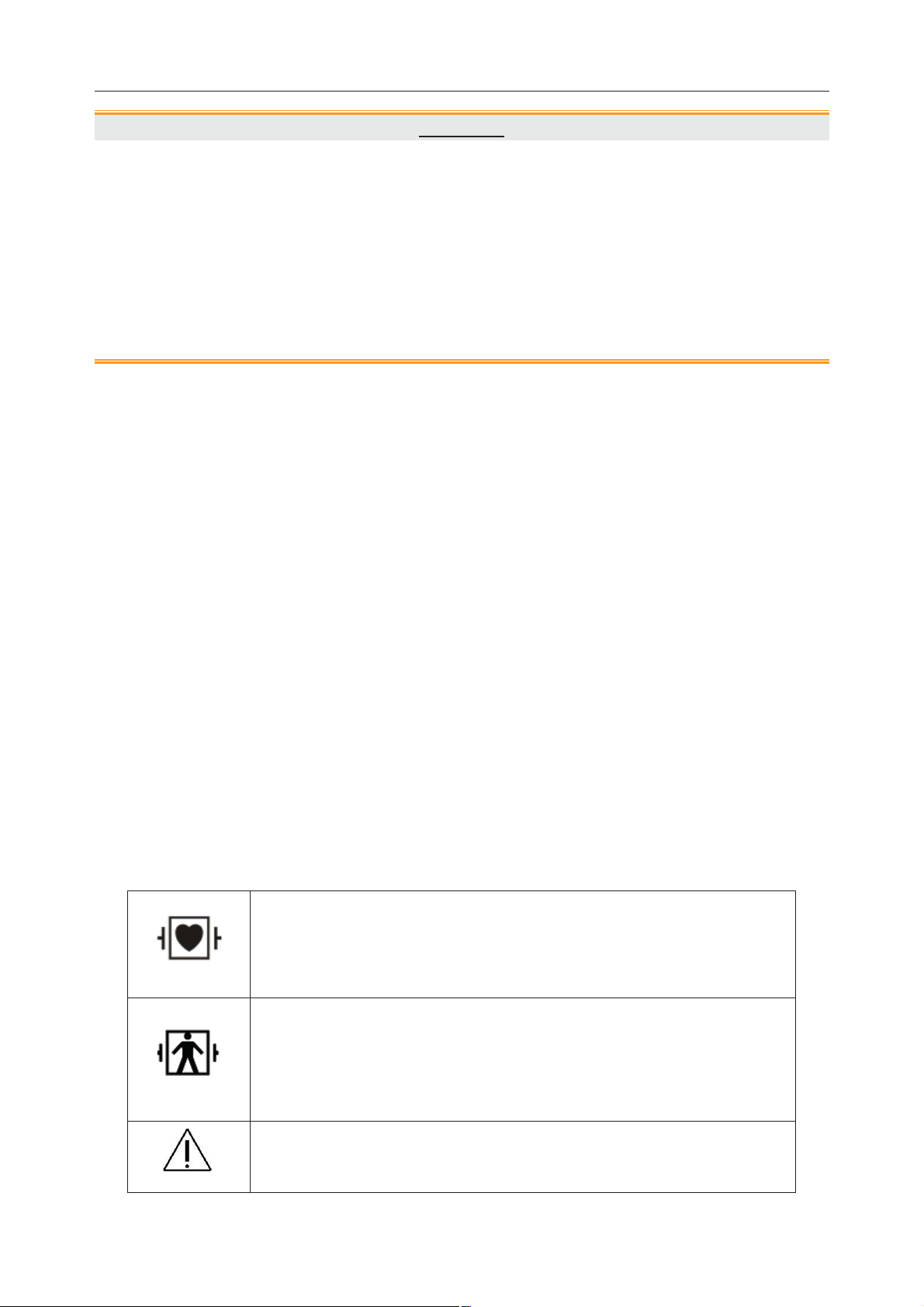
This symbol indicates that the equipment is IEC/EN60601-1 Type CF
equipment. The unit displaying this symbol contains an F-Type
isolated (floating) patient applied part providing a high degree of
protection against shock, and is suitable for use during defibrillation.
This symbol indicates that the instrument is IEC/EN 60601-1 Type
BF equipment. The unit displaying this symbol contains an F-Type
isolated (floating) patient applied part providing a high degree of
protection against shock, and is suitable for use during defibrillation.
Symbol for “Caution”
- 4 -
Page 20
Patient Monitor User Manual Intended Use and Safety Guidance
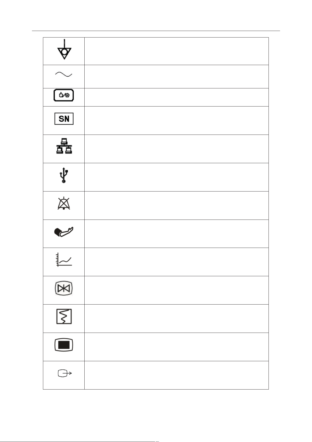
Equipotential grounding terminal
Alternating Current
Power Supply switch
Serial number
Network port
USB (Universal Serial Bus) Connection
Audio alarm is off
NIBP measurement
Trend graph
Freeze
Record
Menu
VGA output, External Monitor
- 5 -
Page 21

Patient Monitor User Manual Intended Use and Safety Guidance
RS-232 port
Nurse call port
SD Card port
Signal output port
Signal output
The symbol indicates that the device complies with the European
Council Directive 93/42/EEC concerning medical devices.
Authorized representative in the European community
Date of manufacture
Manufacturer
P/N Part Number
Recycle
The symbol indicates that the device should be sent to the special
agencies according to local regulations for separate collection after
its useful life.
Consult Instructions For Use
- 6 -
Page 22

Patient Monitor User Manual Intended Use and Safety Guidance
Locked position
Gas inlet
Gas outlet (evac)
ISA equipped to measure CO
only.
2
ISA equipped to measure multiple gases.
Federal (U.S.) Law restricts this device to sale by or on the order of a
physician.
(Only applicable to iM50 and iM80) With respect to electrical shock,
fire and mechanical hazards only in accordance with UL 60601-1and
CAN/CSA C22.2 No. 601.1, IEC 60601-2-25*, IEC 60601-2-27,
IEC 60601-2-30,IEC 60601-2-34, IEC 60601-2-49, IEC
60601-2-51* (Symbol * means this standard only applicable to
iM80)
- 7 -
Page 23

Patient Monitor User Manual Installation
Chapter 2 Installation
NOTE:
1 The monitor settings must be specified by the authorized hospital personnel.
2 To ensure that the monitor works properly, please read the user manual and follow
the steps before using the monitor.
2.1 Initial Inspection
Before unpacking, check the packaging and ensure that there are no signs of mishandling or
damage. If the shipping cartons are damaged, contact the carrier for compensation and package
them again.
Open the package carefully and remove the monitor and accessories. Check that the contents are
complete and that the correct options and accessories have been delivered.
If you have any question, please contact your local supplier.
2.2 Mounting the Monitor
If all situations are normal, please place the monitor on a flat, level surface, hung on the bed rail,
or mounted on a wall. About how to install the wall mount for the monitor, please refer to the
following content.
2.2.1 Installing Wall Mount for the Monitor
For how to install wall mount for the monitor, please refer to Wall Mounting Bracket Assembly
Instruction.
2.3 Connecting the Power Cable
Connection procedure of the AC power line is listed below:
1 Make sure the AC power supply complies with the following specifications: 100V-240V~,
50Hz/60Hz.
2 Apply the power line provided with the monitor. Plug the power line to inlet interface of the
monitor. Connect the other end of the power line to a grounded 3-phase power output.
NOTE:
Connect the power line to the jack special for hospital usage.
2.4 Checking Out the Monitor
Make sure there is no damage on the measurement accessories and cables. Then turn on the
monitor, check whether the monitor can start normally. Make sure all alarm lamps light up and
the alarm sound is heard when turning on the monitor.
- 8 -
Page 24

Patient Monitor User Manual Installation
WARNING
If any sign of damage is detected, or the monitor displays some error messages, do not
use it on any patient. Contact Customer Service Center immediately.
NOTE:
1 Check all the functions of the monitor and make sure that the monitor is in good
status.
2 If rechargeable batteries are provided, charge them after using the device every time,
to ensure the electric power is enough.
3 The interval between double pressing of POWER switch should be longer than 1
minute.
4 After continuous 360-hour runtime, please restart the monitor to ensure the monitor’s
steady performance and long lifespan.
2.5 Checking the Recorder
If your monitor is equipped with a recorder, open the recorder’s door to check if paper is properly
installed in the slot. If no paper exists, refer to Chapter Recording for details.
2.6 Setting the Date and Time
To set the date and time:
1. Select Menu > Maintenance > User Maintain > Date/Time Setup.
2. Adjust the date display format based on the user’s habit.
3. Set the correct time of year, month, day, hour, min and sec.
2.7 Handing Over the Monitor
If you are handing over the monitor to the end-users directly after configuration, make sure that it
is in the monitoring mode.
The users must be adequately trained to use the monitor before monitoring a patient. To achieve
this, they should have access to, and read, the following documentation delivered with the
monitor:
z User Manual (this book) - for full operating instructions.
z Quick Reference Card - for quick reminders during use.
2.8 FCC Statement*
*The statement is not applicable to iM50 or iM80.
This equipment has been tested and found to comply with the limits for a Class B digital device,
pursuant to part 15 of FCC Rules. These limits are designed to provide reasonable protection
against harmful interference in a residential installation. This equipment generates and can radiate
radio frequency energy and, if not installed and used in accordance with the instructions, may
- 9 -
Page 25

Patient Monitor User Manual Installation
cause harmful interference to radio communications. However, there is no guarantee that
interference will not occur in a particular installation. If this equipment does cause harmful
interference to radio or television reception, which can be determined by turning the equipment
off and on, the user is encouraged to try to correct the interference by one or more of the
following measures:
1. Reorient or relocate the receiving antenna.
2. Increase the separation between the equipment and receiver.
3. Connect the equipment into an outlet on a circuit different from that to which the receiver is
connected.
4. Consult the dealer or an experienced radio/TV technician for help.
This device complies with Part 15 of FCC Rules.
Operation is subject to the following two conditions:
1. This device may not cause harmful interference, and
2. This device must accept any interference received, including interference that may cause
undesired operation.
NOTE:
The manufacturer is not responsible for any radio or TV interference caused by
unauthorized modifications to this equipment. Such modifications could void the user’s
authority to operate this equipment.
2.9 FCC RF Radiation Exposure Statement*
*The statement is not applicable to iM50 or iM80.
This equipment complies with FCC RF radiation exposure limits set forth for an uncontrolled
environment. This equipment should be installed and operated with a minimum distance of 20
centimeters between the radiator and your body.
- 10 -
Page 26
Patient Monitor User Manual Basic Operation
Chapter 3 Basic Operation
This manual is for clinical professionals using the iM50/iM60/iM70/iM80 patient monitors.
Unless otherwise specified, the information here is valid for all the above products.
This user manual describes all features and options. Your monitor may not have all of them; they
are not all available in all geographies. Your monitor is highly configurable. What you see on the
screen, how the menus appear and so forth, depend on the way it has been tailored for your
hospital and may not be exactly as shown here.
3.1 Overview
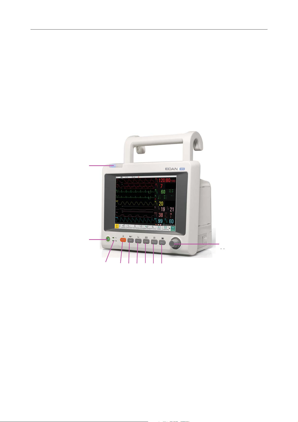
3.1.1 Front View
1
2
10
3 4 5 6
7
iM50
89
- 11 -
Page 27

Patient Monitor User Manual Basic Operation
1
2
10
3 4 5 6 7 8 9
iM60
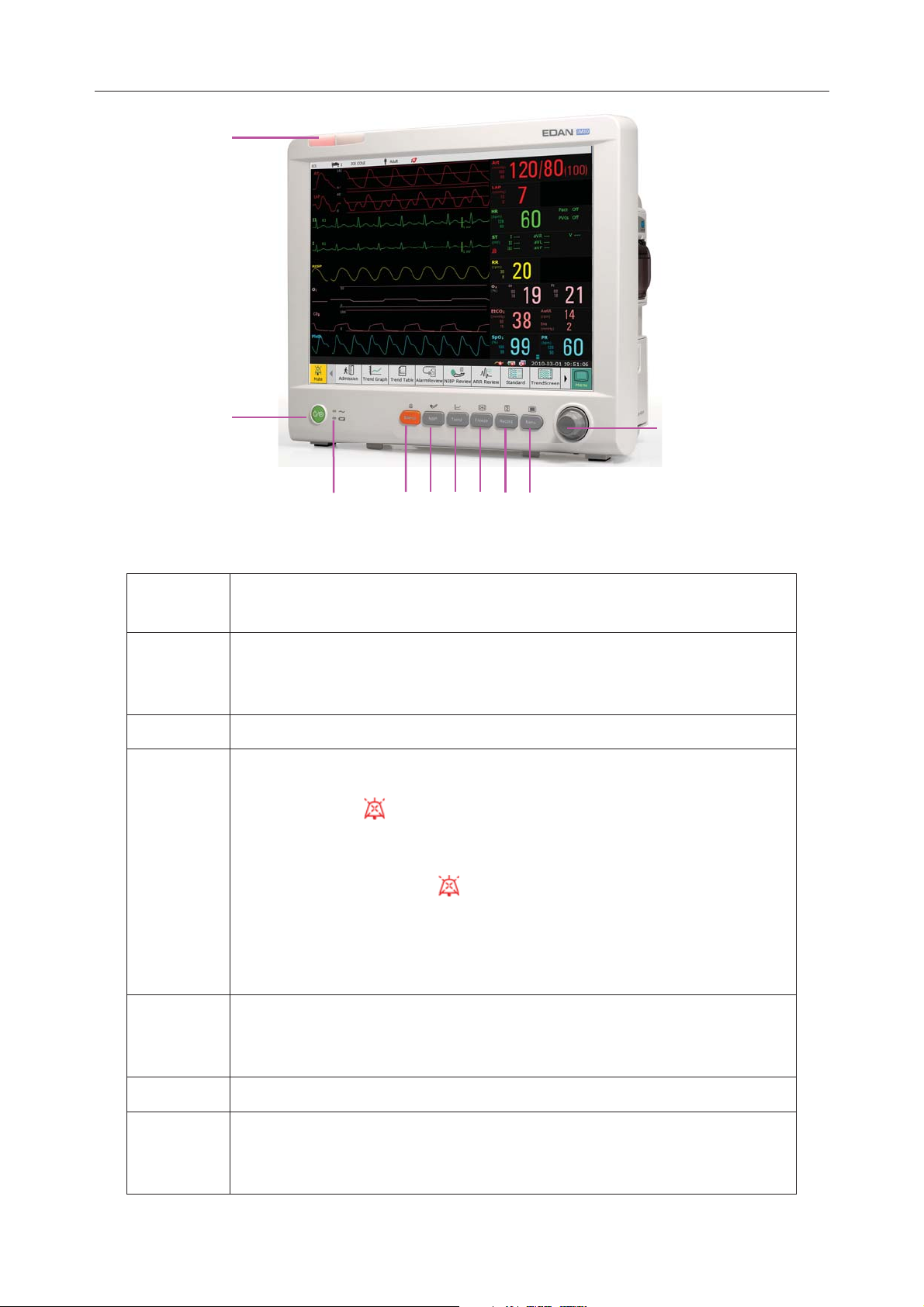
1
2
10
3 4 5 6 7 8 9
iM70
- 12 -
Page 28
Patient Monitor User Manual Basic Operation
1
2
3
4
56789
iM80
10
1 Alarm indicator — when an alarm occurs, the alarm indicator will light
or flash. The color of light represents the alarm level.
2 Power supply switch — when the monitor is connected to the AC power
supply, press the key to turn the monitor on. When the monitor is turned
on, press the key to turn the monitor off.
3 Battery indicator, refer to Section Battery Indicator for details.
4 Mute — Press this button to pause the alarm. All the audio alarm will be
closed. At the same time, the message of Temporary Alarm Mute **s
and the symbol
will be displayed in the information area. When you
repress it or the pause time is over, the system will resume the normal
monitoring status and the message of Temporary Alarm Mute **s and
icon will vanish. Symbol
is shown in the information area. Pressing
or holding the button again can resume the alarm.
Further Alarm Mute information can be found in the chapter Alarm
Mute.
5 Start / Stop NIBP measurement — Press this button to inflate the cuff
and start blood pressure measurement. During the measurement, press the
button to stop the measurement.
6 Trend Key — Press this button to enter trend table review interface.
7 Freeze /Unfreeze — In normal mode, press this button to freeze all the
waveforms on the screen. In Freeze mode, press this button to restore the
waveform refreshing.
- 13 -
Page 29
Patient Monitor User Manual Basic Operation
8 Start / Stop Recording — Press this button to start a real-time recording.
During the recording, press this button again to stop recording.
9 Menu — Press this button to return to the main interface when there is no
menu open.
10 Rotary Knob (hereinafter called knob) — The user can rotate the knob
clockwise or anticlockwise. This operation can make the highlighted item
shift up, down, left or right to choose the desired item. Remember, when
using the knob, rotate this button to highlight, and press it to select the
item.
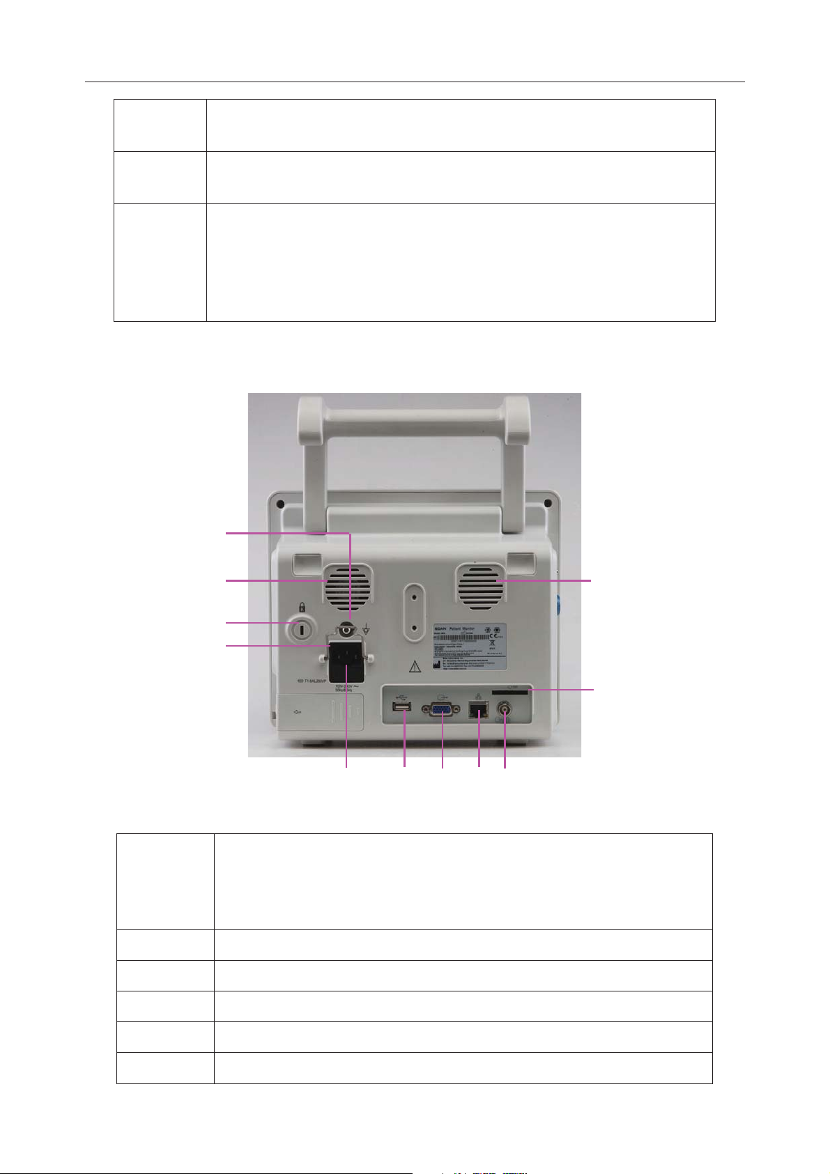
3.1.2 Rear View
1
2
3
4
10
11
5 6 7 8 9
iM50
1 Equipotential grounding terminal, if the monitor or other processing
unit are used in internal examinations on the heart, ensure that the room
incorporates an equipotential grounding system to which the monitor
and other processing unit have separate connection.
2 Fan
3 Anti-theft lock interface
4 Security lock, used to prevent the power supply cord from falling.
5 Power Supply Inlet
6 USB interface, this port is used to connect the USB device.
- 14 -
Page 30

Patient Monitor User Manual Basic Operation
7 VGA Interface
8 Network interface, this port is used to connect to the central monitoring
system through the standard network wire.
9 Defibrillator synchronization / analog output. When the user selects
Analog Output, the monitor outputs the waveform through the
auxiliary output port. When the user selects Defibrillation the monitor
outputs the defibrillator synchronization signal through the auxiliary
output port.
10 Speaker
11 SD Card
1
2
3
4
5
6 7
iM60/iM70
8
9
10
11
1 SD Card
2 USB interface, this port is used to connect the USB device.
3 Network interface, this port is used to connect to the central
monitoring system through the standard network wire.
4 VGA output
- 15 -
Page 31

Patient Monitor User Manual Basic Operation
5 Defibrillator synchronization/ analog output/ nurse call port:
When the user selects Analog Output, the monitor outputs the
waveform through the auxiliary output port. When the user
selects Defibrillation, the monitor outputs the defibrillator
synchronization signal through the auxiliary output port. When
the port is used as nurse call port, it is connected to the call
system. When there is an alarm, the monitor outputs nurse call
signal to notify the nurse.
6 Anti-theft lock interface
7 Heat sink
8 Speaker
9 Equipotential grounding terminal, if the monitor or other
processing unit are used in internal examinations on the heart,
ensure that the room incorporates an equipotential grounding
system to which the monitor and other processing unit have
separate connection.
10 Power Supply Inlet
11 Security lock, used to prevent the power supply cord from falling.
1
2
3
4
5
13
12
11
6
7
8
iM80
- 16 -
9
10
Page 32

Patient Monitor User Manual Basic Operation
1 SD Card
2 Nurse call port, this port is connected to the call system. When
there is an alarm, the monitor outputs nurse call signal to notify
the nurse.
3 Defibrillator synchronization / analog output. When the user
selects Analog Output, the monitor outputs the waveform
through the auxiliary output port. When the user selects
Defibrillation, the monitor outputs the defibrillator
synchronization signal through the auxiliary output port.
4 VGA output
5 USB interface, this port is used to connect the USB device.
6 RS232 interface
7 Network interface, this port is used to connect to the central
monitoring system through the standard network wire.
8 Anti-theft lock interface
9 Heat emission hole
10 Security lock, used to prevent the power supply cord from falling.
11 Equipotential grounding terminal, if the monitor or other
processing unit are used in internal examinations on the heart,
ensure that the room incorporates an equipotential grounding
system to which the monitor and other processing unit have
separate connection.
12 Speaker
13 Fan
- 17 -
Page 33

Patient Monitor User Manual Basic Operation
3.1.3 Side View
1
3
2
4
iM50
1 Sensor interface
2 CO2 module holder
3 Recorder door
4 Battery door
1
3
2
4
iM60/iM70
- 18 -
Page 34

Patient Monitor User Manual Basic Operation
1 Sensor port
2 CO2 module holder
3 Recorder door
4 Battery door
1
2
iM80
3
4
1 Sensor port
2 AG module holder
3 Recorder door
4 Battery door
- 19 -
Page 35

Patient Monitor User Manual Basic Operation
3.1.4 Configuration
Model Size (L×W×H) Function Configuration
iM50 261 mm (L) × 198 mm (W) × 215 mm (H)
ECG, RESP, SpO
IBP ,TEMP, Quick TEMP,
, NIBP,
2
CO2
iM60 303mm(L) × 161mm(W) × 254mm(H)
iM70 328mm(L) × 158mm(W) × 285mm(H)
ECG, RESP, SpO2, NIBP,
TEMP, IBP, C.O., CO
ECG, RESP, SpO
TEMP, IBP, C.O., CO
2
, NIBP,
2
,
2
AG
iM80 370 mm (L) × 175 mm (W) × 320 mm (H)
ECG, RESP, SpO
TEMP, IBP, C.O., CO
, NIBP,
2
,
2
AG
3.2 Operating and Navigating
Everything you need to operate the monitor is contained on its screen. Almost every element on
the screen is interactive. Screen elements include measurement data, waveforms, screen keys,
information fields, alarms fields and menus. The configurability of the monitor means that often
you can access the same element in different ways. For example, you might be able to access an
item through its on-screen setup menu, via a hard key, or via a shortcut key. The User Manual
always describes how to access items via an on-screen menu. You may use whichever way you
find most convenient.
- 20 -
Page 36

Patient Monitor User Manual Basic Operation
1 Department
2 Bed number
3 Patient name
4 Patient type
5 Alarm status area
6 Alarm off
7 Measurement value
8 Menu
9 Date and time
10 Scroll right to display more shortcut keys
11 Networking symbol
12 Battery status symbol
13 AC power supply symbol
- 21 -
Page 37

Patient Monitor User Manual Basic Operation
14 Shortcut key area
15 Scroll left to display more shortcut keys
16 Mute key
17 Parameter waveform
3.2.1 Using Keys
The monitor has four different types of keys:
3.2.1.1 Permanent Keys
A permanent key is a graphical key that remains on the screen all the time to give you fast access
to functions.
Menu – enter the main setup menu.
Mute key – close the audio alarm to switch off the alarm.
3.2.1.2 Shortcut Keys
A shortcut key is a configurable graphical key, located at the bottom of the main screen. It gives
you fast access to functions. The selection of shortcut keys available on your monitor depends on
your monitor configuration and on the options purchased.
Perform a 12-lead analysis
Exit from 12-lead analysis
Access the 12-lead review
Perform 12-lead record
Switch to the standard screen
Switch to the OxyCRG screen
Switch to the large font screen
Set the module switch
Admit a patient
Review the trend graph
- 22 -
Change the key volume
Adjust the screen brightness
Page 38

Patient Monitor User Manual Basic Operation
Review the trend table
Review the alarm event
Access the NIBP review
Access the ARR review
Switch to the trend screen
Select this item by the trim knob to enable the touch screen operation
Zero the IBP sensor
Alarm setup
Change the beat volume
Enter standby mode
Enter night mode
3.2.1.3 Hardkeys
A hardkey is a physical key on a monitoring device, such as the recording key on the front panel.
3.2.1.4 Pop-up keys
Pop-up keys are task-related graphical keys that appear automatically on the screen when
required. For example, the confirmation pop-up key appears only when you need to confirm a
change.
3.3 Operating Mode
3.3.1 Demo Mode
To change the operating mode into the demo mode, please refer to the following procedure:
Select Menu > Common Function, then choose Demo Mode from the popup interface and input
password 3045.
After entering Demo Mode, the monitor will perform the followings:
z Storing no data of new patient.
z Pausing to give all types of alarm.
z Pausing to transmit patient data to CMS and other network devices.
z Pausing to store the currently recorded data, and clearing the memory used to store
recording and printing data.
- 23 -
Page 39

Patient Monitor User Manual Basic Operation
z Real data: the parameter measurement value and real waveform displayed on the screen
are from the predefined analog data, not the truly monitoring patients’ data.
z History data: the monitor will store the analog real-time data in Demo mode, including
trend data, patient information, alarm event, waveform and setting.
To exit Demo Mode, select Menu > Common Function > Demo Mode to exit.
WARNING
This is for demonstration purposes only. You must not change into Demo Mode during
monitoring. In Demo Mode, all stored trend information is deleted from the monitor’s
memory.
3.3.2 Standby Mode
Standby mode can be used when you want to temporarily interrupt monitoring. To enter standby
mode, please press the shortcut key
anything on the screen or press any key.
on the screen directly. To resume monitoring, select
3.3.3 Night Mode
To switch to night mode, you may:
z Select the shortcut key
z Select Menu> Common Function> Night Mode.
NOTE:
In night mode, the sound of key, heart beat and pulse is muted; the alarm volume and
screen brightness are down to their minimum; the settings including key volume, beat
volume, PR volume, alarm volume and screen brightness are unavailable.
on the main screen, or
3.4 Changing Monitor Settings
3.4.1 Adjusting Screen Brightness
To change the screen brightness, please:
1. Press the Brightness key on the screen directly or.
2. Select Menu > Common Function > Brightness, and select the appropriate setting for the
screen brightness. 10 is the brightest, 1 is the least bright.
Your monitor may be configured with lower brightness in standby mode and also for transport to
conserve battery power.
- 24 -
Page 40

Patient Monitor User Manual Basic Operation
3.4.2 Changing Date and Time
To change the date and time, please refer to Section Setting Date and Time.
WARNING
Change to date and time will influence the storage of trend data.
3.5 Adjusting Volume
3.5.1 Adjusting Key Volume
The key volume is the volume you hear when you select any field on the monitor screen or when
you turn the knob. To adjust the key volume, please:
1. Select the Key Volume key on the screen directly or.
2. Select Menu > System Setup > Key Volume, then select the appropriate setting for the key
volume: Five is the loudest and Zero is the quietest.
3.5.2 Adjusting Alarm Volume
To change the alarm volume, please
1. Press the Alarm Volume key on the screen directly or.
2. Select Menu > Alarm Setup > Alarm Volume, and select the desired setting from the
popup interface. For detailed information, please refer to Section Controlling Alarm Volume.
3.5.3 Adjusting Beat Volume
To change the beat volume, please press the Beat Volume key on the screen directly or refer to
Section Setting Beat Volume.
3.6 Checking Your Monitor Version
To check the monitor version, please select Menu > Common Function > About to check the
monitor software revision.
3.7 Networked Monitoring
Your monitor can be connected to the wired network. If the monitor is networked, a network
symbol is displayed on the screen.
- 25 -
Page 41

Patient Monitor User Manual Basic Operation
3.8 Setting Languages
To change the language, please:
1. Select Menu > Maintenance > User Maintain, then type the correct password ABC into the
displayed interface.
2. Select the Language option on the popup interface to open the language list.
3. Select the desired language from the list. To make the change validate, please restart the
monitor.
3.9 Understanding Screens
Your monitor comes with a set of preconfigured screens, optimized for common monitoring
scenarios such as OR adult, or ICU neonatal. A screen defines the overall selection, size and
position of waves, numeric and shortcut keys on the monitor screen when you switch on the
monitor. You can easily switch between different screens during monitoring. Screens do NOT
affect alarm settings, patient category and so forth. When you switch from a complex to a less
complex screen layout, some measurements may not be visible but are still monitored in the
background. For detailed information, please refer to Chapter User Interface.
3.10 Calibrating Screens
To calibrate the screen, please refer to the following steps:
1. Select Menu > Maintenance > User Maintain, then input maintenance password ABC,
then select TouchScr Calibration from the popup interface.
2. The symbol
3. Click on the central point of the symbol
4. After successful calibration, the message of Screen Calibration Completed appears on the
screen. Then select Exit to finish the calibration.
appears on the screen.
.
3.11 Disabling the Touch Screen
The user can disable touch screen operation by pressing and holding the Menu shortcut key for 3
seconds. A message of Screen Locked and the symbol are displayed at the bottom of screen
if the touch screen is disabled. To enable the touch screen operation, turn the knob to select the
symbol
and press it.
- 26 -
Page 42

Patient Monitor User Manual Basic Operation
3.12 Using the Barcode Scanner
To enter the barcode setup menu, please select Menu > Maintenance > User Maintain, after
entering the required password ABC, select Other Setup > BarCode Setup. Then the user can
set serial No, last Name, first Name and so on.
If Auto Update is set to On, the patient information is updated automatically by using a bar code
scanner. If Auto Update is set to Off, the user needs to update the patient information manually.
3.13 Resolving IBP Label Conflicts
Each label must be unique and can only be assigned once. The measurement labels are stored in
the measurement modules. If you try to use two IBP channels that have identical labels, this
causes a label conflict in the monitor.
For example, an IBP channel (channel A) has already been loaded and the label Art is used for
channel A. Then another IBP channel (channel B) is loaded and the label Art is also used for
channel B. In this case, a label conflict will be triggered. A prompt indicating IBP label conflict
will appear on the left of the screen. Additionally, at the corresponding measurements area, a
label flickers to indicate a label conflict. The flickering label is the default one assigned by the
system.
The IBP channel with a label conflict will not provide any measurement data; besides, the
functions of setup, zeroing and calibrating are unavailable. To resolve the label conflict, you have
to change the conflicting label into a non-conflicting one via the following method:
1 Select the IBP channel with a label conflict on the screen and open the Options menu.
2 Choose another label among the options from the Alias pull-down list to resolve the label
conflict.
- 27 -
Page 43

Patient Monitor User Manual Alarms
Chapter 4 Alarms
The alarm information here applies to all measurements. Measurement-specific alarm
information is discussed in the sections of individual measurements.
WARNING
A potential hazard can exist if different alarm presets are used for the same or similar
equipment in any single area, e.g. an intensive care unit or cardiac operating room.
4.1 Alarm Category
The monitor provides two types of alarms: physiological alarms and technical alarms.
4.1.1 Physiological alarms
If one or several physiological parameters of the currently monitored patient exceed the
predefined alarm limit, for example: SpO2 values exceed the alarm limit, the monitor will give an
alarm, and this type of alarm is called physiological alarms. About the detailed alarm information,
please refer to the Section physiological alarm information.
4.1.2 Technical Alarms
If one or several technical status of the device is in abnormal status, such as: lead off or low
battery and so on, the monitor will give an alarm. And this type of alarm is called technical
alarms. About the detailed alarm information, please refer to Section technical alarm
information.
4.1.3 Prompts
The monitor can give the character indication of monitoring process or other functions, such as:
ARR Relearning and so on. And this character is called prompts. About the detailed alarm
information, please refer to Section Prompts.
4.2 Alarm Levels
In terms of severity, the device’s alarm levels can be classified into three categories: high level
alarms, medium level alarms and low level alarms.
1. High level alarms
Indicating that the patient is in a life threatening situation and an emergency treatment is
demanded.
2. Medium level alarms
The patient’s vital signs appear abnormally or the device system status is abnormal,
indicating that prompt operator response is required.
- 28 -
Page 44

Patient Monitor User Manual Alarms
3. Low level alarms
The patient’s vital signs appear abnormal or the device system status appears abnormally,
indicating that operator awareness is required.
The high/medium/low-level alarms are indicated by the system in following different ways:
Alarm
level
High
Medium
Prompt
Physiological alarms Technical alarms
The alarm indicator
Mode is
“DO-DO-DO------DODO,
DO-DO-DO------DO-D
O”, which is triggered
once every 10 seconds.
flashes in red, with a
frequency of 1.4Hz
2.8Hz.The alarm
message flashes with red
background, and the
symbol
*** is displayed at
the alarm area.
The alarm indicator
flashes in yellow, with a
frequency of 0.4Hz
Mode is “DO-DO-DO”,
which is triggered once
every 25 seconds.
0.8Hz. The alarm
message flashes with
yellow background, and
the symbol ** is
displayed at the alarm
area.
The alarm indicator
flashes in red. The alarm
message flashes with red
background, and the
symbol
*** is displayed at
the alarm area.
No definition
Low
Mode is “DO-”, which
is triggered once every
30 seconds.
The alarm indicator
flashes in yellow. The
alarm message flashes
with yellow background,
and the symbol * is
displayed at the alarm
The alarm indicator
flashes in blue. The alarm
message flashes with
yellow background, and
the symbol * is displayed
at the alarm area.
area.
The sound pressure range for audible alarm signals is from 45 dB to 84 dB.
4.3 Controlling Alarm
4.3.1 Setting Parameter Alarm
Parameter alarm settings including alarm switch, alarm record, alarm level and alarm limit are
available on the respective alarm setup menu for each parameter. To access the menu for
parameter alarm settings, use the shortcut key
click Alarm Options to open the menu shown below for alarm settings of each parameter. Also,
you can access this menu via the respective parameter setup menu.
or select Menu> Alarm Setup, and then
- 29 -
Page 45

Patient Monitor User Manual Alarms
Upper arrow or
lower arrow to
increase or
decrease the
alarm limit
Setting value of
high alarm limit
High
Alarm Limit
Setting value of
low alarm limit
Low
Alarm Limit
WARNING
1 When the alarm is set to OFF, the monitor won’t give an alarm prompt even if an
alarm occurs. In order to avoid endangering the patient’s life, the user should use this
function cautiously.
2 Prior to monitoring, make sure that the alarm limit settings are appropriate for your
patient.
3 Setting alarm limits to extreme values may cause the alarm system to become
ineffective.
4.3.2 Temporary Alarm Mute
The monitor will give an audible alarm when there is an alarm during the audio alarm pause and
the alarm indicator and screen flash indicating there is an alarm. The top of monitor displays the
following:
1. Alarm pause symbol
2. The remaining pause time is displayed in text and the word background is red.
The user can set the audio alarm pause to 60 s, 120 s, or 180 s based on the requirement.
4.3.3 Alarm Mute
To mute the alarm, please select Menu > Maintenance > User Maintain > Alarm Setup, and
set Mute to On, then press the
press the Silence shortcut key on the screen directly.
And alarm reminder tone DO is heard every three minutes.
key on the front panel for more than three seconds or
- 30 -
Page 46

Patient Monitor User Manual Alarms
4.3.4 Controlling Alarm Volume
The monitor provides five levels of alarm volume: 1, 2, 3, 4 and 5. For adjusting the alarm
volume, please refer to Section Adjusting Alarm Volume.
4.4 Latching Alarms
To set the alarm latch function, please select Menu > Maintenance > User Maintain > Alarm
Setup and set Alarm Latch from the pull-down list. If it is set to On, when an alarm occurs, the
monitor will display the alarm message of the parameter in the alarm status area. If the parameter
resumes to normal, the alarm information of this parameter still displays in the alarm display area
and the alarm time is also displayed. If many parameters appear to be latching alarms, the alarm
messages are displayed in the physiological alarm message area in turn.
To deselect the alarm latch, please set Alarm Latch to Off. When Alarm Latch is set to Off, the
latch function is invalid.
4.5 Disabling Sensor Off Alarms
To set sensor off alarm, please select Menu > Maintenance > User Maintain and enter the
required password ABC. Then select Alarm Setup and set Sensor Off Alm from the pull-down
list. If it is set to On, and a sensor off alarm occurs, the user can press the Mute key on the front
panel to disable the alarm signal. Then the alarm indicator stops flashing, and the monitor is in
temporary mute alarm status. If the user presses the Mute key again or the temporary mute time
ends, no audible alarm for sensor-off status will be resumed. Instead, sensor-off status will be
announced with a prompt message.
4.6 Testing Alarms
When you switch the monitor on, a self test is started. You must check that the alarm indicator
lights and that you hear a single tone. This indicates that the visible and audible alarm indicators
are functioning correctly. For further testing of individual measurement alarms, perform the
measurement on yourself or use a simulator. Adjust alarm limits and check that appropriate alarm
behavior is observed.
- 31 -
Page 47

Patient Monitor User Manual Alarm Information
Chapter 5 Alarm Information
5.1 Physiological Alarm Information
Message Cause Alarm level
HR High HR measuring value is above the upper alarm limit. User-selectable
HR Low HR measuring value is below the lower alarm limit. User-selectable
ST measuring value is above the upper alarm limit. (X
ST-X High
ST-X Low
PVCs High PVCs measuring value is above the upper alarm limit. User-selectable
ASYSTOLE No QRS is detected for 4 consecutive seconds High
VFIB/VTAC
stands for I, II, III, aVR, aVL, aVF, V, V1, V2, V3,
V4, V5 or V6)
ST measuring value is below the lower alarm limit.(X
stands for I, II, III, aVR, aVL, aVF, V, V1, V2, V3,
V4, V5 or V6)
Ventricular tachycardia: The RR interval of 4-second
fibrillation wave or 5 consecutive ventricular beats is
less than 600 ms.
User-selectable
User-selectable
High
VT>2 3< the number of cluster PVCs < 5 User-selectable
COUPLET 2 consecutive PVCs User-selectable
BIGEMINY Vent Bigeminy User-selectable
TRIGEMINY Vent Trigeminy User-selectable
A type of single PVC under the condition that
HR<100ˈR-R interval is less than 1/3 the average
R ON T
PVC Single PVC detected in normal heartbeats. User-selectable
TACHY
BRADY
interval, followed by a compensating pause of 1.25X
the average R-R interval (the next R wave advances
onto the previous T wave).
Adult: 5 consecutive QRS complex, RR interval <
0.5s (HR range: 120~300bpm).
Pediatric/neonatal: 5 consecutive QRS complex, RR
interval <
Adult: 5 consecutive QRS complex, RR interval
1.5s (HR range: 15~40bpm).
Pediatric/neonatal: 5 consecutive QRS complex, RR
interval 1s (HR range: 15~60bpm).
0.375s (HR range: 160~350bpm).
User-selectable
User-selectable
User-selectable
- 32 -
Page 48

Patient Monitor User Manual Alarm Information
Message Cause Alarm level
When HR is less than 120 beats/min., no heart beat is
tested during the period 1.75 times of the average RR
MISSED BEATS
interval; or
User-selectable
When HR is 120 beats/min, no beat is tested within 1
second.
IRR
heart rate.
User-selectable
PACE NOT CAPTURE: After the pacemaker is
IRREGULAR RHYTHM: The patient has irregular
PNC
paced, QRS complex can not be detected during
User-selectable
300ms.
PACER NOT PACED: After the QRS complex, no
PNP
pace is detected during 1.75 times of RR interval.
User-selectable
VENTRICULAR BRADYCARDIA: The interval of 5
VBRADY
consecutive ventricular wave is more than 1000 ms.
User-selectable
VENTRICULAR RHYTHM: The interval of 5
VENT
consecutive ventricular wave ranges from 600 ms to
User-selectable
1000 ms.
RESP APNEA
RESP can not be measured within the set apnea alarm
delay time.
High
RR High RR measuring value is above upper alarm limit. User-selectable
RR Low RR measuring value is below lower alarm limit. User-selectable
SpO2 High
SpO2 Low
SpO2 No Pulse
SpO2 measuring value is above upper alarm limit.
SpO2 measuring value is below lower alarm limit.
The signal of the measurement site is too weak, so the
User-selectable
User-selectable
High
monitor can’t detect the pulse signal.
PR High
PR measuring value is above upper alarm limit.
User-selectable
PR Low PR measuring value is below lower alarm limit. User-selectable
T1 High
T1 Low
T2 High
T2 Low
TD High
Measuring value of T1 channel is above upper alarm
limit.
Measuring value of T1 channel is below lower alarm
limit.
Measuring value of T2 channel is above upper alarm
limit.
Measuring value of T2 channel is below lower alarm
limit.
Measuring value of TD channel is above upper alarm
limit.
User-selectable
User-selectable
User-selectable
User-selectable
User-selectable
- 33 -
Page 49

Patient Monitor User Manual Alarm Information
Message Cause Alarm level
SYS High SYS measuring value is above upper alarm limit. User-selectable
SYS Low SYS measuring value is below lower alarm limit. User-selectable
DIA High DIA measuring value is above upper alarm limit. User-selectable
DIA Low DIA measuring value is below lower alarm limit. User-selectable
MAP High MAP measuring value is above upper alarm limit. User-selectable
MAP Low MAP measuring value is below lower alarm limit. User-selectable
Art SYS High Art SYS measuring value is above upper alarm limit. User-selectable
Art SYS Low Art SYS measuring value is below lower alarm limit. User-selectable
Art DIA High Art DIA measuring value is above upper alarm limit. User-selectable
Art DIA Low Art DIA measuring value is below lower alarm limit. User-selectable
Art MAP High Art MAP measuring value is above upper alarm limit. User-selectable
Art MAP Low Art MAP measuring value is below lower alarm limit. User-selectable
PA SYS High PA SYS measuring value is above upper alarm limit. User-selectable
PA SYS Low PA SYS measuring value is below lower alarm limit. User-selectable
PA DIA High PA DIA measuring value is above upper alarm limit. User-selectable
PA DIA Low PA DIA measuring value is below lower alarm limit. User-selectable
PA MAP High PA MAP measuring value is above upper alarm limit. User-selectable
PA MAP Low PA MAP measuring value is below lower alarm limit. User-selectable
CVP MAP High CVP MAP measuring value is above upper alarm limit. User-selectable
CVP MAP Low CVP MAP measuring value is below lower alarm limit. User-selectable
ICP MAP High ICP MAP measuring value is above upper alarm limit. User-selectable
ICP MAP Low ICP MAP measuring value is below lower alarm limit. User-selectable
LAP MAP High LAP MAP measuring value is above upper alarm limit. User-selectable
LAP MAP Low LAP MAP measuring value is below lower alarm limit. User-selectable
RAP MAP High RAP MAP measuring value is above upper alarm limit. User-selectable
RAP MAP Low RAP MAP measuring value is below lower alarm limit. User-selectable
P1 SYS High P1 SYS measuring value is above upper alarm limit. User-selectable
P1 SYS Low P1 SYS measuring value is below lower alarm limit. User-selectable
P1 DIA High P1 DIA measuring value is above upper alarm limit. User-selectable
P1 DIA Low P1 DIA measuring value is below lower alarm limit. User-selectable
P1 MAP High P1 MAP measuring value is above upper alarm limit. User-selectable
P1 MAP Low P1 MAP measuring value is below lower alarm limit. User-selectable
- 34 -
Page 50

Patient Monitor User Manual Alarm Information
Message Cause Alarm level
P2 SYS High P2 SYS measuring value is above upper alarm limit. User-selectable
P2 SYS Low P2 SYS measuring value is below lower alarm limit. User-selectable
P2 DIA High P2 DIA measuring value is above upper alarm limit. User-selectable
P2 DIA Low P2 DIA measuring value is below lower alarm limit. User-selectable
P2 MAP High P2 MAP measuring value is above upper alarm limit. User-selectable
P2 MAP Low P2 MAP measuring value is below lower alarm limit. User-selectable
EtCO2 High EtCO2 measuring value is above upper alarm limit. User-selectable
EtCO2 Low EtCO2 measuring value is below lower alarm limit. User-selectable
FiCO2 High FiCO2 measuring value is above alarm limits. User-selectable
CO2 APNEA
In the set apnea alarm delay time interval, no RESP
can be detected using CO2 module.
High
AwRR High AwRR measuring value is above upper alarm limit. User-selectable
AwRR Low AwRR measuring value is below lower alarm limit. User-selectable
EtCO2 (AG) High
EtCO2 (AG) Low
EtCO2 (AG) measuring value is above upper alarm
limit.
EtCO
(AG) measuring value is below lower alarm
2
limit.
User-selectable
User-selectable
FiCO2 (AG) High FiCO2 (AG) measuring value is above alarm limits. User-selectable
AwRR (AG) High
AwRR (AG) Low
AwRR (AG) measuring value is above upper alarm
limit.
AwRR (AG) measuring value is below lower alarm
limit.
User-selectable
User-selectable
EtO2 High EtO2 measuring value is above upper alarm limit. User-selectable
EtO2 Low EtO2 measuring value is below lower alarm limit. User-selectable
FiO2 High FiO2 measuring value is above upper alarm limit. User-selectable
FiO2 Low FiO2 measuring value is below lower alarm limit. User-selectable
EtN2O High EtN2O measuring value is above upper alarm limit. User-selectable
EtN2O Low EtN2O measuring value is below lower alarm limit. User-selectable
FiN2O High FiN2O measuring value is above upper alarm limit. User-selectable
FiN2O Low FiN2O measuring value is below lower alarm limit. User-selectable
EtHAL High EtHAL measuring value is above upper alarm limit. User-selectable
EtHAL Low EtHAL measuring value is below lower alarm limit. User-selectable
FiHAL High FiHAL measuring value is above upper alarm limit. User-selectable
FiHAL Low FiHAL measuring value is below lower alarm limit. User-selectable
- 35 -
Page 51

Patient Monitor User Manual Alarm Information
Message Cause Alarm level
EtENF High EtENF measuring value is above upper alarm limit. User-selectable
EtENF Low EtENF measuring value is below lower alarm limit. User-selectable
FiENF High FiENF measuring value is above upper alarm limit. User-selectable
FiENF Low FiENF measuring value is below lower alarm limit. User-selectable
EtISO High EtISO measuring value is above upper alarm limit. User-selectable
EtISO Low EtISO measuring value is below lower alarm limit. User-selectable
FiISO High FiISO measuring value is above upper alarm limit. User-selectable
FiISO Low FiISO measuring value is below lower alarm limit. User-selectable
EtSEV High EtSEV measuring value is above upper alarm limit. User-selectable
EtSEV Low EtSEV measuring value is below lower alarm limit. User-selectable
FiSEV High FiSEV measuring value is above upper alarm limit. User-selectable
FiSEV Low FiSEV measuring value is below lower alarm limit. User-selectable
EtDES High EtDES measuring value is above upper alarm limit. User-selectable
EtDES Low EtDES measuring value is below lower alarm limit. User-selectable
FiDES High FiDES measuring value is above upper alarm limit. User-selectable
FiDES Low FiDES measuring value is below lower alarm limit. User-selectable
AG FiO2 Low FiO2 measure value is extremely low. High
AG APNEA
In the set apnea alarm delay time interval, no RESP
can be detected using AG module.
High
TB High TB measuring value is above upper alarm. User-selectable
TB Low TB measuring value is below lower alarm. User-selectable
- 36 -
Page 52

Patient Monitor User Manual Alarm Information
5.2 Technical Alarm Information
NOTE:
The ECG alarm information listed in the below table describes the lead names in
America. For the corresponding lead names in Europe, please refer to Section Installing
Electrodes.
Message Cause Alarm Level Action Taken
1) The drive lead or more
than one ECG limb
ECG Lead Off
electrode falls off the skin;
2) ECG cables fall off the
monitor.
Low
ECG V Lead Off
ECG LL Lead Off
ECG LA Lead Off
ECG RA Lead Off
ECG Signal Exceed
ECG electrode V falls off
the skin or the ECG cable
V falls off the monitor.
ECG electrode LL falls off
the skin or the ECG cable
LL falls off the monitor.
ECG electrode LA falls off
the skin or the ECG cable
LA falls off the monitor.
ECG electrode RA falls off
the skin or the ECG cable
RA falls off the monitor.
ECG measuring value is
beyond measuring range.
Low
Low
Low
Low
High
Make sure that all
electrodes, leads and
patient cables are
properly connected.
Check lead
connection and
patient condition
ECG Signal Overflow
The amplitude of ECG
signal is too wide.
- 37 -
Low
Please modify the
ECG gain.
Page 53

Patient Monitor User Manual Alarm Information
Message Cause Alarm Level Action Taken
Stop measuring
function of ECG
ECG Comm Fail
ECG module failure or
communication failure
High
module, and notify
biomedical engineer
or manufacturer’s
service staff.
ECG Noise
ECG V1 Lead Off
ECG V2 Lead Off
ECG V3 Lead Off
ECG V4 Lead Off
ECG measuring signal is
greatly interrupted.
ECG electrode V1 falls off
the skin or the ECG cable
V1 falls off.
ECG electrode V2 falls off
the skin or the ECG cable
V2 falls off.
ECG electrode V3 falls off
the skin or the ECG cable
V3 falls off.
ECG electrode V4 falls off
the skin or the ECG cable
V4 falls off.
Low
Low
Low
Low
Low
Check lead
connection and
patient condition
Make sure that all
electrodes, leads and
patient cables are
properly connected.
ECG V5 Lead Off
ECG V6 Lead Off
RESP Comm Fail
ECG electrode V5 falls off
the skin or the ECG cable
V5 falls off.
ECG electrode V6 falls off
the skin or the ECG cable
V6 falls off.
RESP module failure or
communication failure
- 38 -
Low
Low
High
Stop measuring
function of RESP
module, and notify
biomedical engineer
or the manufacturer’s
service staff.
Page 54

Patient Monitor User Manual Alarm Information
Message Cause Alarm Level Action Taken
Check whether
interference to the
respiratory signal
RR Exceed
RR measuring value is out
of the measure range (less
than 6rpm or greater than
150rpm).
Medium
exists. And check
whether the patient is
breathing normally;
breathing too rapidly
or too slowly may
endanger patient’s
life.
Check whether the
patient is breathing
normally. Take
measures to help the
patient breathe
normally when
necessary. If the
patient is breathing
normally, try to
adjust the electrode
RESP Cardiac Artifact
No RESP waveform can
be detected due to apnea or
shallow breathing of the
patient.
High
position on the
patient in order to
reduce the
interference of
cardiogenic artifact.
RESP Noise
SpO2 Sensor Off
SpO2 Sensor Err
SpO2 No Sensor
RR cannot be measured
due to patient movement.
sensor may be
SpO
2
disconnected from the
Low
Low
patient or the monitor.
Malfunction in the SpO
sensor or in the extension
2
Low
cable.
SpO
sensor was not
2
connected well or
connected to the monitor,
Low
or the connection is loose.
- 39 -
Check whether the
RESP leads are well
connected. Keep the
patient calm for
better monitoring.
Make sure the sensor
is well connected to
the patient’s finger
or other parts.
Replace the SpO2
sensor or the
extension cable.
Make sure the
monitor and sensor
is well connected,
reconnect the sensor.
Page 55

Patient Monitor User Manual Alarm Information
Message Cause Alarm Level Action Taken
Stop using
measuring function
SpO2 Comm Fail
SpO2 module failure or
communication failure
High
of SpO
notify biomedical
engineer or
module, and
2
manufacturer’s
service staff.
The pulse signal is too
SpO2 Low Perfusion
weak or the perfusion of
the measurement site is
too low
There is interference with
SpO
measurement signals
SpO2 Noisy Signal
2
and the waveform is
abnormal.
SpO2 Light
Interference
Ambient light around the
sensor is too strong.
Low
Low
Low
Reconnect the SpO
2
sensor and change
the measurement
site. If problem
exists, please notify
biomedical engineer
or manufacturer’s
service staff.
Check the condition
of patient and avoid
patient movement;
make sure the cable
is well connected.
Reduce interference
of the ambient light
and avoid sensor’s
exposure to strong
light.
NIBP Comm Fail
NIBP module failure or
communication failure
- 40 -
High
Stop using
measuring function
of NIBP module, and
notify biomedical
engineer or
manufacturer’s
service staff.
Page 56

Patient Monitor User Manual Alarm Information
Message Cause Alarm Level Action Taken
Properly wrap the
cuff and connect the
tube. Measure again;
if failure persists,
NIBP Leak
NIBP pump, valve, cuff or
tube has a leakage.
Low
stop measuring
function of NIBP
module and notify
biomedical engineer
or manufacturer’s
service staff.
Measure again, if
failure persists, stop
NIBP Excessive
Pressure
Pressure has exceeded the
specified upper safety
limit.
Low
measuring function
of NIBP module and
notify biomedical
engineer or
manufacturer’s
service staff.
NIBP Init Pressure
High
NIBP Self Test Error
NIBP Cuff Type
Error
The initial pressure is too
high during measuring
Sensor or other hardware
errors.
The cuff type used isn’t
consistent with the patient
type.
Low
High
Low
Measure again, if
failure persists, stop
measuring function
of NIBP module and
notify biomedical
engineer or
manufacturer’s
service staff.
If failure persists,
stop using measuring
function of NIBP
module and notify
biomedical engineer
or manufacturer’s
service staff.
Confirm the patient
type and change the
cuff.
- 41 -
Page 57

Patient Monitor User Manual Alarm Information
Message Cause Alarm Level Action Taken
Check whether the
airway is occluded
or pressure sensor
works properly. If
the problem still
Air Pressure Error
Malfunction in pressure
sensor or valve
Low
exists, contact your
service personnel.
NIBP System Failure Malfunction in hardware High
NIBP Weak Signal
Cuff is too loose or patient
Low
pulse is too weak.
Maybe the patient blood
NIBP Range Exceeded
pressure value is beyond
Low
the measurement range.
Cuff is not properly
NIBP Loose Cuff
wrapped or no cuff is
Low
connected.
NIBP Interference
Signal noise is too large or
pulse rate is not regular.
Low
Contact your service
personnel.
Check the
connection of the
cuff and try again. If
failure persists, use
other methods to
measure blood
pressure.
Use other methods
to measure blood
pressure.
Properly wrap the
cuff.
Make sure that the
patient under
monitoring is
motionless.
HW Excessive
Pressure
Hardware excessive
pressure protection
Measuring time has
NIBP Time Out
exceeded the specified
time.
Temperature cable of
TEMP T1 Sensor Off
TEMP channel 1 may be
disconnected from the
monitor.
- 42 -
High
Low
Low
Notify biomedical
engineer or
manufacturer’s
service staff.
Measure again or
use other measuring
methods.
Make sure that the
cable is properly
connected
Page 58

Patient Monitor User Manual Alarm Information
Message Cause Alarm Level Action Taken
TEMP T2 Sensor Off
Excessive T1
Excessive T2
TEMP Comm Fail
Temperature cable of
TEMP channel 2 may be
disconnected from the
Low
monitor.
TEMP1 measuring value is
beyond measuring range.
TEMP2 measuring value is
beyond measuring range.
TEMP module failure or
communication failure.
High
High
High
Make sure that the
cable is properly
connected.
Check sensor
connection and
patient condition
Check sensor
connection and
patient condition
Stop measuring
function of TEMP
module, and notify
biomedical engineer
or Manufacturer’s
service staff.
YY Sensor Off (YY
stands for the IBP
label name)
YY Comm Fail (YY
stands for the label
name)
C.O. Comm Fail
C.O. TI No Sensor
IBP sensor falls off. Low
IBP module failure or
communication failure
C.O. module failure or
communication failure
C.O. TI sensor not
connected
High
High
Low
Check the sensor
connection and
reconnect the sensor.
Stop measuring
function of IBP
module, and notify
biomedical engineer
or Manufacturer’s
service staff.
Stop measuring of
C.O. module, or
notify biomedical
engineer or
Manufacturer’s
service staff.
Insert injective
temperature sensor.
C.O. TB No Sensor
TEMP Out Of Range
C.O. TB sensor not
connected
TB measuring value is
above measuring range.
- 43 -
Low Insert TB sensor.
High
Please check TB
sensor.
Page 59

Patient Monitor User Manual Alarm Information
Message Cause Alarm Level Action Taken
C.O. Lack Param
C.O. measuring needs
parameters
High
The AA concentration
AA Out Of Range
exceeds the accuracy range
High
of AG module.
The oxygen sensor of the
O2 Sensor Error
sidestream AG module has
Medium
a failure.
AG Comm Fail
AG module failure or
communication failure.
High
AG Zero Required AG module requires zero. Low
Please input patient’s
height and weight.
Reduce AA
concentration.
Stop measuring of
AG module, and
notify biomedical
engineer or
Manufacturer’s
service staff.
Stop measuring
function of AG
module, and notify
biomedical engineer
or Manufacturer’s
service staff.
Please perform
zeroing.
AG Self-Testing AG module is self testing. Low
AG Replace O2
Sensor
O2 sensor needs to be
replaced.
High
AG Check Adapter AG module checks adapter. Low
Please wait the self
testing finishing.
Please replace the O2
sensor.
Please wait check
finishing.
O2 Cali Required O2 needs to be calibrated. Low Please calibrate O2.
AG Software Error
AG Hardware Error
AG Motor Error
AG module software
abnormal
AG module has hardware
failure.
AG module motor
abnormal
High
High
High
AG Uncalibrated AG module uncalibrated Low
Please replace
software revision.
Please check whether
the hardware work
properly.
Please check whether
the motor works
properly.
Please calibrate the
AG module.
AG Replace Adapter
AG module needs to
change adapter.
- 44 -
High
Please replace the
adapter.
Page 60

Patient Monitor User Manual Alarm Information
Message Cause Alarm Level Action Taken
O2 Out Of Range O2 is out of range. High
AG TEMP Out Of
Range
AG Baro Press Out
Of Range
AG AA Id Unreliable
AG Span Calib In
Progress
AG Calibration Fail
Unable To Calibrate
AG module temperature
out of range
AG module baro pressure
out of pressure
AG module can’t identify
the AG agent.
High
High
Medium
AG module is calibrating. Low
AG module calibration
failure
AG module can’t be
calibrated.
Medium
Medium
Please make O
2
range resume
normal.
Please make the
temperature resume
normal.
Please make the baro
pressure value
resume normal.
Reduce gas agent
type.
Please wait
calibration finishing.
Please check whether
the module works
properly.
Please check whether
the module works
properly.
AG Zero In Progress AG module is zeroing. Low Please wait zeroing.
AG Occlusion
The sampling line is
clogged.
Medium
AG Init Fail AG module has a failure. High
AG Data Limit Error AG module has a failure. High
AG Usa Error AG module has a failure. High
AG Cal Fail
AG module fails to
calibrate.
High
AG Zref Fail AG module fails to zero. High
AG Change Oxygen
Sensor
AG No Oxygen
Sensor
Replace oxygen sensor of
AG module.
The oxygen sensor falls off
from the AG module.
Low
High
Replace the
sampling line.
AG module works
improperly.
AG module works
improperly.
AG module works
improperly.
AG module works
improperly.
AG module works
improperly.
Please wait changing
finishing.
Connect the sensor
again.
- 45 -
Page 61

Patient Monitor User Manual Alarm Information
Message Cause Alarm Level Action Taken
AG Mixed Agents
CO2 Occlude
CO Out Of Range
AG module detects mixture
gas agent.
Water trap of SideStream is
occluded.
The CO
concentration
2
exceeds the accuracy range
Medium
High
High
of CO2 module.
CO2 Sensor Faulty CO2 module failure High
CO2 Sensor Over
Temp
CO2 measure value exceeds
the measure range of the
monitor.
High
Close the subsidiary
gas agent.
Make sure the gas
exhaust works well
Reduce CO
2
concentration.
Stop measuring
function of CO
2
module, notify
biomedical engineer.
Stop measuring
function of CO
2
module, notify
biomedical engineer.
CO
module failure or
CO2 Comm. Failed
2
communication failure
High
CO2 Zero Required Zero calibration failure Low
Check if the water
tray has been fixed.
Disconnect the
sampling cannula or
adapter from the
airway; initiate the
zeroing before
making sure that no
expired air is inside
the sampling cannula
and adapter.
- 46 -
Page 62

Patient Monitor User Manual Alarm Information
Message Cause Alarm Level Action Taken
1) For the
CO2 Check Adapter
1) For the Respironics CO
2
module: The cannula is off
or disconnected.
2) For the EDAN CO2
Low
module: The water trap is
disconnected or not
properly connected.
Respironics CO
module: Check
whether the adapter
is properly connected
or replace the
adapter.
2) For the EDAN
module:
CO
2
2
Properly connect the
water trap.
AA Out Range
O2 Sensor Error
QuickTemp Comm
Fail
Temp exceed limit
The AA concentration
exceeds the accuracy range
of AG module.
The oxygen sensor of the
sidestream AG module has
a failure.
TEMP module failure or
communication failure.
The TEMP value is beyond
the range of +25qC ~
+45qC.
High
Medium
High
Med
Reduce AA
concentration.
Stop measuring of
AG module, and
notify biomedical
engineer or
Manufacturer’s
service staff.
Stop measuring
function of TEMP
module, and notify
biomedical engineer
or manufacturer’s
service staff.
Put the sensor into
the sensor bracket,
take it out and
measure again.
No Temp Sensor
Ambient temp too
high
TEMP sensor is not
connected to the TEMP
module.
The Sensor temperature is
higher than +40qC.
- 47 -
Low
Low
Connect the sensor
and the monitor well,
and measure again.
Put the sensor into
the sensor bracket,
measure again after
the ambient
temperature reaches
normal value.
Page 63

Patient Monitor User Manual Alarm Information
Message Cause Alarm Level Action Taken
Put the sensor into
the sensor bracket,
Ambient temp too low
The Sensor temperature is
Low
lower than +10qC.
measure again after
the ambient
temperature reaches
normal value.
Put the sensor into
the sensor bracket,
take it out and
measure again. If the
Probe data error
Offline: NTC resistance >R
0 qC; Short: NTC
resistance <R+100 qC.
Med
problem persists,
stop using measuring
function of TEMP
module, and notify
biomedical engineer
or manufacturer’s
service staff.
Probe heater error Single failure Med
The original temperature of
Probe temp too high
sensor >+33 qC & +40
Low
qC.
After the sensor
temperature reaches Predict
Temp Sensor Off
value, it descends to the
Med
value lower than Predict
value.
Put the sensor into
the sensor bracket,
take it out and
measure again. If the
problem persists,
stop using measuring
function of TEMP
module, or notify
biomedical engineer
or manufacturer’s
service staff.
Put the sensor into
the sensor bracket,
measure again after
the sensor
temperature reaches
normal value.
Reconnect the sensor
and make sure that
the cable is properly
connected.
- 48 -
Page 64

Patient Monitor User Manual Alarm Information
Message Cause Alarm Level Action Taken
Battery Low
Battery Low
Recorder Out Of
Paper
Recorder Out Of Paper Low
The user presses the
Recorder setup
needed
RECORD button when the
monitor is not installed
with a recorder.
Removable device is
full
Removable dev
read-only
Less than 10M space is left
in the removable device.
The removable device is
read-only.
High
Low
Low
Low
Please change the
battery or charging.
Please install the
paper
Notify the
manufacturer’s
service staff to install
and set the recorder.
Delete some data in
the removable device
or use another
removable device.
Repair the removable
device or replace it
with a new one.
5.3 Prompts
Message Cause
ECG Arr Learning
SpO2 Search Pulse
Manual Measuring In manual measuring mode
Continual Measuring In continuous measuring mode
Auto Measuring In automatic measuring mode
Measure Abort Measurement over
Calibrating During calibrating
Calibrate Abort Calibration over
The QRS template building required for Arr. Analysis is in
process.
SpO2 module is analyzing the patient signal and searching
for the pulse to compute the saturation, when sensor is
connected with patient.
Leak Testing During pneumatic test
Leak Test Ok NIBP module has passed leak test.
Leak Test Abort Pneumatic test over
- 49 -
Page 65

Patient Monitor User Manual Alarm Information
Message Cause
Resetting NIBP module in resetting
Please Start NIBP module is in idle status.
Done NIBP measurement successfully done
Continual Measuring NIBP module performs continual measuring
Stat Measuring NIBP module performs STAT function.
NIBP module is in normal mode, the user can’t start leak
Please Switch To Maintain Mode
test and pressure calibration. Please enter User Maintain >
NIBP Maintain and switch to Maintain Mode to perform
leak test or pressure calibration.
NIBP module is in maintaining mode, the user can’t start
Please Switch To Normal Mode
blood pressure measurement. Please enter User Maintain
> NIBP Maintain and switch to Normal Mode to perform
blood pressure measurement.
Quick TEMP Is Warming Up Quick TEMP Is Warming Up.
Place Probe On Measure Place Probe isn’t placed on the measurement site.
CO2 Standby
Turn from measuring mode to standby mode, making the
module in energy-saving status.
CO2 Sensor Warm Up The CO2 module is in warm-up state.
Zeroing... The CO2 module is performing the zero calibration.
Excessive C.O. Temp TB measuring value is beyond measuring range.
Excessive Temp, C.O.
Measurement Fail.
C.O. measuring needs parameters.
C.O. measure need param HEMOD calculation needs parameters.
Insufficient factors for Hemod
Dynamics
No Sensor, C.O. measurement
fail
HEMO Dynamics calculation needs parameters.
No Sensor,C.O. measurement fail
Measuring... The C.O. module is performing measuring.
Ready for new measurement C.O. module is ready for new measurement.
Invalid C.O. result C.O. measurement result is invalid.
C.O. Measurement Complete C.O. Measurement is completed.
C.O. Measurement Abort C.O. Measurement is aborted.
Warm-up over The monitor displays this message after taking the sensor
out of the bracket and warm-up is over.
- 50 -
Page 66

Patient Monitor User Manual Alarm Information
Message Cause
Measure over After the Predict measuring is over, the data and message
display on the interface.
Measure time out No measuring result after the module entering Predict
state for 30s.
AG Standby AG module is operating in the standby status.
5.4 Adjustable Range of Alarm Limits
ECG alarm limits are listed as follows: unit (bpm)
Patient Type ALM HI ALM LO
HR ADU 300 15
PED 350 15
NEO 350 15
ST analysis alarm limits are listed as follows: unit (mV)
ALM HI ALM LO
ST 2.0 -2.0
PVCs alarm upper limits are listed as follows:
ALM HI ALM LO
PVCs 10
- 51 -
Page 67

Patient Monitor User Manual Alarm Information
RESP alarm limits are listed as follows: unit (rpm)
Patient Type ALM HI ALM LO
ADU 120 6
PED 150 6
NEO 150 6
SpO2 alarm limits are listed as follows (unit %):
ALM HI ALM LO
SpO2 100 0
PR alarm limits is listed as follows: unit (bpm)
ALM HI ALM LO
PR 300 30
NIBP alarm limits are listed as follows (EDAN module): unit (mmHg)
Patient Type ALM HI ALM LO
ADU SYS
DIA
MAP
PED SYS
DIA
MAP
NEO SYS
DIA
MAP
270
215
235
200
150
165
135
100
110
40
10
20
40
10
20
40
10
20
NIBP alarm limits are listed as follows (Omron module): unit (mmHg)
Patient Type ALM HI ALM LO
SYS
250
60
ADU(PED)
NEO
DIA
MAP
SYS
DIA
MAP
200
235
120
90
100
- 52 -
40
45
40
20
30
Page 68

Patient Monitor User Manual Alarm Information
TEMP alarm limits are listed as follows:
ALM HI ALM LO
T1
T2
TD
50qC (122 º F) 0qC (32 º F)
50qC (122 º F)
50qC (90 º F)
IBP alarm limits are listed as follows: unit (mmHg)
ALM HI ALM LO
Art 300 0
RAP 40 -10
LAP 40 -10
CVP 40 -10
PA 120 -6
ICP 40 -10
P1 300 -50
P2 300 -50
0qC (32 º F)
0qC (0 º F)
CO2 alarm limits are listed as follows:
ALM HI ALM LO
EtCO2 150 mmHg 0
FiCO2 50 mmHg 3
AwRR 150 rpm 2 rpm
C.O. alarm limits are listed as follows:
ALM HI ALM LO
TB
43qC (109.4) 23qC(73.4)
Quick Temp alarm limits are listed as follows:
Patient Type ALM HI ALM LO
ADU
PED
42qC (107.6) 35.5qC (95.9)
42qC (107.6) 35.5qC (95.9)
- 53 -
Page 69

Patient Monitor User Manual Alarm Information
AG alarm limits are listed as follows:
Patient Type ALM HI ALM LO
ADU FiCO2
EtCO2
FiO2
EtO
2
FiN2O
EtN2O
EtDes
FiDes
EtIso
FiIso
EtHal
FiHal
EtSev
FiSev
25.0%
25.0%
88.0%
90.0%
100.0%
100.0%
18.0%
18.0%
5.0%
5.0%
5.0%
5.0%
8.0%
8.0%
0.0%
0.0%
18.0%
18.0%
0.0%
0.0%
0%
0%
0%
0%
0%
0%
0%
0%
EtEnf
FiEnf
awRR
Apnea Time
PED FiCO2
EtCO2
FiO
2
EtO2
FiN2O
EtN2O
EtDes
FiDes
EtIso
FiIso
5.0%
5.0%
150 rpm
40s
25.0%
25.0%
88.0%
90.0%
100.0%
100.0%
18.0%
18.0%
5.0%
5.0%
0%
0%
0 rpm
20s
0.0%
0.0%
18.0%
18.0%
0.0%
0.0%
0%
0%
0%
0%
EtHal
FiHal
- 54 -
5.0%
5.0%
0%
0%
Page 70

Patient Monitor User Manual Alarm Information
EtSev
FiSev
EtEnf
FiEnf
awRR
Apnea Time
NEO FiCO2
EtCO2
FiO2
EtO
2
FiN2O
EtN2O
EtDes
FiDes
8.0%
8.0%
5.0%
5.0%
150 rpm
40s
25.0%
25.0%
88.0%
90.0%
100.0%
100.0%
18.0%
18.0%
0%
0%
0%
0%
0 rpm
20s
0.0%
0.0%
18.0%
18.0%
0.0%
0.0%
0%
0%
EtIso
FiIso
EtHal
FiHal
EtSev
FiSev
EtEnf
FiEnf
awRR
Apnea Time
5.0%
5.0%
5.0%
5.0%
8.0%
8.0%
5.0%
5.0%
150 rpm
40 s
0%
0%
0%
0%
0%
0%
0%
0%
0 rpm
20 s
- 55 -
Page 71

Patient Monitor User Manual Managing Patients
Chapter 6 Managing Patients
6.1 Admitting a Patient
The monitor displays physiological data and stores it in the trends as soon as a patient is
connected. This allows you monitor a patient who is not yet admitted. It is however important to
admit patients properly so that you can identify your patient on recordings, reports, and
networked devices.
During admission you enter data that the monitor needs for safe and accurate operation. For
example, the patient category setting determines the algorithm the monitor uses to process and
calculate some measurements, the safety limits that are applied for some measurements, and the
alarm limit ranges.
To admit a patient, please:
1. Select the Admission key on the screen or.
2. Select Menu > Patient Setup > New Patient, then a message is displayed to ask the user to
confirm to update patient.
3. Click on No to cancel this operation; click on Yes, the Patient Info window is displayed.
4. Enter the patient information:
z Serial No: Enter the patient’s medical record number (MRN), for example 12345678.
z Last name: Enter the patient’s last name (family name), for example Smith.
z First name: Enter the patient’s first name, for example Joseph.
z Gender: Male, Female and N/A.
z Type: Choose the patient type, either Adult, Pediat, or Neonat.
z BloodType: N/A, A, B, AB and O.
z Pace: Choose On or Off (You must select On if your patient has a pacemaker).
z Date of Birth: Enter the patient’s date of birth.
z Date of Admission: Enter the patient’s date of admission.
z Height: Enter the patient’s height.
z Weight: Enter the patient’s weight.
z Doctor: Enter any extra information about the patient or treatment.
5. Select Exit.
6.1.1 Patient Category and Paced Status
The patient category setting determines the algorithm the monitor uses to process and calculate
some measurements, the safety limits that are applied for some measurements, and the alarm limit
ranges.
The paced setting determines whether the monitor shows pacemaker pulses or not. When Pace is
set to Off, pace pulses are filtered and therefore do not show in the ECG wave.
- 56 -
Page 72

Patient Monitor User Manual Managing Patients
WARNING
1 Changing the patient category may change the arrhythmia and NIBP alarm limits.
Always check alarm limits to make sure that they are appropriate for your patient.
2 For paced patients, you must set Paced to On. If it is incorrectly set to Off, the monitor
could mistake a pace pulse for a QRS and fail to give an alarm during asystole.
6.2 Quick Admit
If you do not have the time or information to fully admit a patient. Complete the rest of the
patient information later. To quickly admit a patient, please:
1. Select Menu > Patient Setup > Quick Admit, then a message is displayed to ask the user to
confirm to update patient.
2. Click on No to cancel this operation; click on Yes to continue and the Patient Info window
is displayed, choose Type and Pace and set them to the correct mode.
3. Select Exit.
6.3 Editing Patient Information
To edit the patient information after a patient has been admitted, select Menu > Patient Setup >
Patient Info., and make the required changes on the popup interface.
6.4 Updating a Patient
You should always perform an update before starting monitoring for a new patient. When you
select Menu > Patient Setup > Quick Admit, or Menu > Patient Setup > New Patient,a
message of Press ‘Yes’ to create new patient profile by clearing all current patient data... is
displayed.
z If the user selects Yes, the monitor will update the patient information.
z If the user selects No, the monitor won’t update the patient information and returns to
patient setup interface.
NOTE:
Discharging patient will clear the history data in the monitor associated with the patient.
6.5 Central Monitoring System
The monitor can be connected to the central monitoring system. Through the network:
1. The monitor sends patient information, real-time monitoring or measurement data to the
central monitoring system.
2. The real-time monitoring information is displayed on the central monitoring system as the
- 57 -
Page 73

Patient Monitor User Manual Managing Patients
same to the monitor, and the central monitoring system can perform some bilateral control.
For example: changing patient information, alarm limit and so forth.
For detailed information, please refer to MFM-CMS Central Monitoring System User Manual and
CNS Central Monitoring System User Manual.
And the monitor supports HL 7 protocol.
NOTE:
1 Make sure the network connection between the monitor and the central monitoring
system is in good condition when the time synchronization function on the monitor is
active.
2 The time synchronization function might not be available to all software versions of
MFM-CMS. Consult our technical service department or your local distributor for
more information.
- 58 -
Page 74

Patient Monitor User Manual User Interface
Chapter 7 User Interface
7.1 Setting Interface Style
The user can set the interface based on the requirement, and the set options include the following:
z Sweep of the waveform.
z Parameters needing to be monitored.
Change to some settings may have the risk, so only the authorized person can change them. After
changing the settings, please notify the operator.
7.2 Selecting Display Parameters
The user can select the display parameters based on the monitoring and measurement
requirements. To select the parameter, please:
1. Select Menu > System Setup > Module Switch.
2. Select the required parameters from the popup interface.
3. Press Exit to exit the menu and the screen will adjust the parameters automatically.
7.3 Changing Waveform Position
The user can exchange the waveform positions of parameter A and parameter B, please refer to
the following steps to do so:
1. Select waveform A and open the setup menu of waveform A.
2. Select Change from the popup menu and select the desired label name of waveform B from
the pull-down list.
7.4 Changing Interface Layout
To change the interface layout, please refer to the following steps:
1. Select Menu > Display Setting.
2. Select one interface from the popup menu.
3. The user can implement one kind of function screen based on the requirements. If the user
selects the Large Font option, there is no function screen to be selected.
7.5 Viewing Trend Screen
To view the short trend screen, the user can press the Trend Screen key on the screen directly or
select Menu > Display Setting > View Selection > TrendScreen.
- 59 -
Page 75

Patient Monitor User Manual User Interface
7.6 Viewing Oxygen Screen
To view the oxygen screen, the user can press the oxyCRG key on the screen or select Menu >
Display Setting > View Selection > oxyCRG. This interface is always used in NICU because
the SpO
, HR and Resp of the neonate are different from those of adults.
2
7.7 Viewing Large Font Screen
To open the large font screen, please refer to the following steps:
1. Select the Large Font key on the screen directly or.
2. Select Menu > Display Setting > View Selection > Large Font to open this interface.
To view the large font interface of specific parameter, please select the parameter pull-down
dialog on the interface (the red circle shown in the following figure).
- 60 -
Page 76

Patient Monitor User Manual User Interface
7.8 Viewing the Bed View Window
The Bed View window allows you to view one waveform, numeric information of all parameters
and alarm information from another bed on the same network. The monitor enables a maximum
of eight beds to be viewed.
NOTE:
1 The IP addresses of the monitors configured with bed view function should share the
same network segment. The IP addresses of the monitors on the same LAN should
be unique from each other; you cannot use the bed view function in the monitors in
which an IP address conflict exits.
2 To use the bed view function smoothly, make sure the network connection is in good
condition.
3 In the Bed View window, you cannot view the over-limit alarms of physiological
parameters occurring on other beds. Besides, arrhythmia alarms and vital alarms will
be indicated only by alarm icons.
7.8.1 Opening the Bed View Window
Before opening the Bed View window, make sure the bed view function is configured on your
monitor. To open the Bed View window, select Menu> Display Setup and choose Bed View in
the View Selection list.
7.8.2 Settings of the Bed View Window
Click on the Bed View window to open the ViewBed Setup menu on which you can
z Assign a bed to be viewed by selecting the bed No. in the Bed No. list.
z Select the waveform to be displayed on the window in the Wave Type list.
z Use the buttons
window.
and to view more numeric information of parameters in the
7.9 Changing Parameter and Waveform Colors
The user can set the display colors of parameter and waveform as desire. To change the display
color, please select Menu > Maintenance > User Maintain, enter the required password ABC.
Then select Color Select to make color changes on parameter and color.
7.10 User Configuration
Users can save the current monitor’s configuration, delete the saved user configuration and
rename it. Three pieces of user configuration can be saved in the monitor.
- 61 -
Page 77

Patient Monitor User Manual User Interface
To save the user configuration:
1. Select Menu > Maintenance > User Maintain, enter the required password ABC and then
select User Configure.
2. Click on Save, enter a file name for the configuration and confirm it. A message will display
after the operation.
To delete the user configuration:
1. Select Menu > Maintenance > User Maintain, enter the required password ABC and then
select User Configure.
2. Select the configuration file needed to delete from the list, click on Delete and confirm the
operation. A message will display after the operation.
To rename the user configuration:
1. Select Menu > Maintenance > User Maintain, enter the required password ABC and then
select User Configure.
2. Select a configuration file needed to rename from the list and click on Rename.
3. Enter a name for the configuration file and confirm it.
7.11 Default Configuration
To set default configuration, please select Menu > Default and choose a configuration (adult,
pediatric or neonate) based on your patient category. This configuration is factory configuration.
- 62 -
Page 78

Patient Monitor User Manual Monitoring ECG
Chapter 8 Monitoring ECG
8.1 Overview
The electrocardiogram (ECG) measures the electrical activity of the heart and displays it on the
monitor as a waveform and a numeric. This chapter also tells you about arrhythmia monitoring
and ST monitoring.
8.2 ECG Safety Information
WARNING
1 Do not come into contact with the patient, table, or the monitor during defibrillation.
2 Only use the ECG leads supplied by the manufacturer when using the monitor for
ECG monitoring.
3 When connecting the cables and electrodes, make sure no conductive part is in
contact with the ground. Verify that all ECG electrodes, including neutral electrodes,
are securely attached to the patient but not the conductive part or ground.
4 Check every day whether there is skin irritation resulted from the ECG electrodes. If
yes, replace electrodes every 24 hours or change their sites.
5 Place the electrode carefully and ensure a good contact.
6 Check if the lead connection is correct before monitoring. If you unplug the ECG cable
from the socket, the screen will display the error message “ECG LEAD OFF” and the
audible alarm is activated.
7 When using the monitor with the defibrillator or other high-frequency equipment,
please use defibrillator-proof ECG lead to avoid burn.
8 In order to avoid being burnt, please keep the electrodes far away from the radio knife
while using electrosurgical equipment.
9 When using Electrosurgery (ES) equipment, do not place an electrode near the
grounding plate of the Electrosurgery device: otherwise there will be a great deal of
interference with the ECG signal.
10 For patients with pacemakers, the pacing impulse analysis function must be switched
ON. Otherwise, the pacing impulse may be counted as normal QRS complex, which
results in failure of ECG LOST error detection.
11 The electrodes should be made of the same metal materials.
12 ECG cables can be damaged when connected to a patient during defibrillation. Check
cables for functionality before using them again.
- 63 -
Page 79

Patient Monitor User Manual Monitoring ECG
NOTE:
1 Interference from a non-grounded instrument near the patient and ESU interference
can cause inaccuracy of the waveform.
2 IEC/EN60601-1-2 (protection against radiation is 3v/m) specifies that the electrical
field density exceeding 1v/m may cause measurement error in various frequencies. It
is accordingly suggested that do not use equipment generating electrical radiation
near ECG/RESP monitoring devices.
3 The simultaneous use of cardiac pacemaker and other patient-connected equipment
may cause safety hazard.
4 If the pacemaker signals are beyond the claimed range, the heart rate may be
calculated incorrectly.
5 In the default settings of the monitor, the ECG waveforms are the first two waveforms
from top in the waveform area.
6 For measurements in or near the heart we recommend connecting the monitor to the
potential equalization system.
7 For protecting environment, the used electrodes must be recycled or disposed of
properly.
8.3 ECG Display
The figure below is for reference only.
The symbol “ķ”indicates lead name of display waveform: there are other leads for selection,
such as I, II, III, aVR, aVF, aVL, V. If you want to change the lead, please refer to section
Selecting Calculation Lead.
The symbol “ĸ” indicates waveform gain: there are several options, such as X0.125, X0.25,
X0.5, X1, X2, X4 and Auto. If you want to change it, please refer to section Changing the size of
the ECG Wave.
The symbol “Ĺ” indicates Filter setting, there are three options: monitoring, surgery, diagnosis.
If you want to change it, please refer to section Changing the ECG Filter Setting.
8.3.1 Changing the Size of the ECG Wave
If any of the displayed ECG waveform is too small or clipped, you can change the size of it on
the screen. First select ECG Wave Setup > ECG Gain, then select an appropriate factor from
the pop-up box to adjust the ECG waveform.
- 64 -
Page 80

Patient Monitor User Manual Monitoring ECG
X0.125 to make strength of ECG signal waveform of 1mV become 1.25mm;
X0.25 to make strength of ECG signal waveform of 1mV become 2.5mm;
X0.5 to make strength of ECG signal waveform of 1mV become 5mm;
X1 to make strength of ECG signal waveform of 1mV become 10mm;
X2 to make strength of ECG signal waveform of 1mV become 20mm;
X4 to make strength of ECG signal waveform of 1mV become 40mm;
Auto let the monitor choose the optimal adjustment factor for all the ECG waves.
8.3.2 Changing the ECG Filter Settings
The ECG filter setting defines how ECG waves are smoothed. An abbreviation indicating the
filter type is shown underneath the lead label on the monitor display. Filter settings do not affect
ST measurement.
To change the filter setting, in the ECG Setup menu, select Filter and then select the appropriate
setting.
– Monitor: Use this mode under normal measurement conditions.
– Surgery: The filter reduces interference to the signal. It should be used if the signal is
distorted by high frequency or low frequency interference. High frequency interference usually
results in large amplitude spikes making the ECG signal look irregular. Low frequency
interference usually leads to a wandering or rough baseline. In the operating room, the Filter
reduces artifacts and interference from electro-surgical units. Under normal measurement
conditions, selecting Surgery may suppress the QRS complexes too much and thus interfere with
the clinical evaluation of the ECG displayed on the monitor.
– Diagnos: Use when diagnostic quality is required. The unfiltered ECG wave is displayed so
that changes such as R-wave notching or discrete elevation or depression of the ST segments are
visible.
8.4 Using ECG Alarms
ECG alarms can be switched on and off and the changes to high and low alarm limits are just like
other measurement alarms, which are described in the Alarms section. Special alarm features
applying only to ECG are described here.
8.5 Selecting Calculation Lead
On the Normal interface, the users can select either 3 LEADS or 5 LEADS for this item. Normal
QRS complex should be:
The normal QRS should be either completely above or below the baseline and it should not
be biphasic. For paced patients, the QRS complexes should be at least twice the height of
pace pulses.
- 65 -
Page 81

Patient Monitor User Manual Monitoring ECG
The QRS should be tall and narrow.
The P-waves and the T-waves should be less than 0.2 mV.
8.6 Monitoring Procedure
8.6.1 Preparation
The skin is a poor conductor of electricity, therefore preparation of the patient's skin is important
to facilitate good electrode contact to skin.
Select sites with intact skin, without impairment of any kind.
Shave hair from sites, if necessary.
Wash sites thoroughly with soap and water. (Never use ether or pure alcohol, because this
increases skin impedance).
Rub the skin briskly to increase capillary blood flow in the tissues and remove skin scurf and
grease.
8.6.2 Connecting ECG Cables
1. Attach clip or snap to electrodes prior to placement.
2. Put the electrodes on the patient. Before attaching, apply some conductive jelly on the
electrodes if the electrodes are not electrolyte self-supplied.
3. Connect the electrode lead to the patient's cable.
CAUTION
To protect the monitor from damage during defibrillation, for accurate ECG information
and to protect against noise and other interference, use only ECG electrodes and cables
specified by EDAN.
8.7 Selecting Lead Type
To change the lead type, please:
1. Select the ECG parameter area, open the ECG Setup menu;
2. Set Lead Type to 3 Leads, 5 Leads or 12 Leads based on the lead used.
8.8 Installing Electrodes
NOTE:
The following table gives the corresponding lead names used in Europe and America
respectively. (Lead names are represented by R, L, F, N, C, C1-C6 in Europe, whose
corresponding lead names in America are RA, LA, LL, RL, V, V1-V6.)
- 66 -
Page 82

Patient Monitor User Manual Monitoring ECG
AHA (American Standard) IEC (Europe Standard)
Electrode Labels Color Electrode Labels Color
RA White R Red
LA Black L Yellow
LL Red F Green
RL Green N Black
V Brown C White
V1 Brown/ Red C1 White/ Red
V2 Brown/ Yellow C2 White/ Yellow
V3 Brown/ Green C3 White/ Green
V4 Brown/Blue C4 White/ Brown
V5 Brown/Orange C5 White/ Black
V6 Brown/Purple C6 White/ Purple
8.8.1 Electrode Placement for 3-lead
Take the American standard for example, see the following figure:
RA placement - directly below the clavicle and near the right shoulder.
LA placement: directly below the clavicle and near the left shoulder.
LL placement - on the left hypogastrium.
Electrode Placement for 3-lead
- 67 -
Page 83

Patient Monitor User Manual Monitoring ECG
8.8.2 Electrode Placement for 5-lead
Take the American standard for example, see the following figure:
RA placement: directly below the clavicle and near the right shoulder.
LA placement: directly below the clavicle and near the left shoulder.
RL placement: on the right hypogastrium.
LL placement: on the left hypogastrium.
V placement: on the chest, the position depends on your required lead selection.
Electrode Placement for 5-lead
NOTE:
To ensure the patient safety, all leads must be attached to the patient.
For 5-lead, attach the V electrode to one of the indicated positions as below:
V1 On the 4th intercostal space at the right sterna margin.
V2 On the 4th intercostal space at the left sterna margin.
V3 Midway between V2 and V4 electrodes.
V4 On the 5th intercostal space at the left clavicular line.
V5 On the left anterior axillary line, horizontal with V4 electrode.
V6 On the left middle axillary line, horizontal with V4 electrode.
V3R-V6R On the right side of the chest in positions corresponding to those on the left.
VE Over the xiphoid position.
V7 On the 5th intercostal space at the left posterior axillary line of back.
V7R On the 5th intercostal space at the right posterior axillary line of back.
- 68 -
Page 84

Patient Monitor User Manual Monitoring ECG
V-Electrode Placement for 5-lead
8.8.3 Electrode Placement for 12-lead
Take the American standard for example. The 12-lead electrodes should be placed on extremities
and chest. The electrodes for extremities should be placed on the skin of legs or arms, the
electrodes placed on chest should follow the doctor’s advice. Please see the following figure.
- 69 -
Page 85

Patient Monitor User Manual Monitoring ECG
Electrode Placement for 12-lead
8.8.4 Recommended ECG Lead Placement for Surgical Patients
WARNING
When using Electrosurgery (ES) equipment, leads should be placed in a position in equal
distance from Electrosurgery electrotome and the ES grounding plate to avoid cautery.
Electrosurgery equipment wire and ECG cable must not be tangled up.
Monitoring ECG leads are mainly used for monitoring the patient’s vital signs. When using the
patient monitor with other electrosurgery equipment, it is advised to use the counteracting
defibrillation ECG lead.
The placement of the ECG leads will depend on the type of surgery that is being performed. For
example, in an open chest surgery the electrodes may be placed laterally on the chest or on the
back. In the operating room, artifacts may affect the ECG waveform due to the use of ES
(Electrosurgery) equipment. To help reduce this you can place the electrodes on the right and left
shoulders, the right and left sides near the abdomen, and the chest lead on the left side at
mid-chest. Avoid placing the electrodes on the upper arms. Otherwise the ECG waveform will be
too small.
- 70 -
Page 86

Patient Monitor User Manual Monitoring ECG
NOTE:
1 If an ECG waveform is not accurate, while the electrodes are tightly attached, try to
change the lead.
2 Interference from a non-grounded instrument near the patient and ESU interference
can cause inaccuracy of the waveform.
8.9 ECG Menu Setup
8.9.1 Setting Alarm Source
To change the alarm source, please select ECG Setup > Alarm Source, then a pop-up box is
displayed:
HR: the monitor considers the HR as HR/PR alarm source;
PR: the monitor considers the PR as HR/PR alarm source;
AUTO: If the Alarm Source is set to Auto, the monitor will use the heart rate from the ECG
measurement as the alarm source whenever the ECG measurement is switched on and at least one
ECG lead can be measured without a technical condition. The monitor will automatically switch
to Pulse as the alarm source if:
–a valid ECG lead can no longer be measured and
–a pulse source is switched on and available.
The monitor then uses the pulse rate from the measurement currently active as system pulse.
While Pulse is the alarm source, all arrhythmia and ECG HR alarms are switched off. If an ECG
lead becomes available again, the monitor automatically uses HR as alarm source.
8.9.2 Smart Lead Off
In 5 LEADS, 12 LEADS mode, if CH1 and CH2 cannot be measured because of the lead off or
other reasons, it can shift to other modes to collect an ECG waveform.
To change smart lead off setting, please select ECG Setup > Smart Leadoff, then a pop-up
menu is displayed.
8.9.3 Setting Beat Volume
Beat volume is from HR or PR, depending on your HR alarm setting. Five selections are
available: 0, 1, 2, 3, 4, 5. 5 indicates the maximum volume. 0 indicates the minimum volume.
To change the beat volume, first select ECG Setup > Beat Volume, and then select an
appropriate volume from the pop-up list.
- 71 -
Page 87

Patient Monitor User Manual Monitoring ECG
8.9.4 ECG Display
It varies with Lead Type. When Lead Type is set to 3 Leads, Display can be set to Normal, and
it can display one ECG waveform on the main screen.
When Lead Type is set to 5 Leads, Display can be set to Normal, Full-Scr and Half-Scr. Select
Normal to display two ECG waveforms on the main screen; select Full-Scr to display seven
ECG waveforms which occupy the area of seven waveforms on the main screen; Select Half-Scr
to display seven ECG waveforms on the screen, occupying the area of four waveforms.
NOTE:
If 3 Leads is selected in the ECG Setup menu, only Normal can be selected for Display
in the sub-menu.
8.9.5 Setting Pace Status
It is important to set the paced status correctly when you start monitoring ECG. To change the
paced status in the ECG Setup menu, select Pace to toggle between On or Off. When Pace is set
to On:
- Pace Pulse Rejection is switched on. This means that pacemaker pulses are not counted as
extra QRS complexes.
|
Paced symbol is displayed as
NOTE:
1 When monitoring a patient with a pacemaker, set Pace to On. If monitoring a patient
without a pacemaker, set Pace to Off.
2 If Pace is set to On, the system will not perform some types of ARR analysis.
Some pace pulses can be difficult to reject. When this happens, the pulses are counted
as a QRS complex, and could result in an incorrect HR and failure to detect cardiac arrest
or some arrhythmias. Keep pacemaker patients under close observation.
on the main screen.
WARNING
8.9.6 ECG Calibration
This item is used to calibrate ECG waveform. When you select this item from ECG Setup menu
again, the ECG waveform calibration ends.
NOTE:
The device can’t be monitored during ECG calibration.
8.9.7 ECG Waveform Settings
To change this speed, select ECG Wave Setup > Sweep, then select an appropriate setting from
the pop-up list. The bigger the value is, the wider the waveform is.
- 72 -
Page 88

Patient Monitor User Manual Monitoring ECG
8.9.8 12 Leads ECG
When the monitor is installed with 12-lead, it can provide 3-lead, 5-lead and 12-lead ECG
monitoring functions.
8.10 ST Segment Monitoring
The monitor performs ST segment analysis on normal and atrially paced beats and calculates ST
segment elevations and depressions. This information can be displayed in the form of ST numeric
and snippets on the monitor.
ST segment monitoring function is shut off by default. You can switch it to On when necessary.
When using the ST analysis function, the ST analysis results will be displayed on the right of the
main screen, please refer to the following figure.
NOTE:
The ST algorithm has been tested for accuracy of the ST segment data. The significance
of the ST segment changes need to be determined by a clinician.
8.10.1 Setting ST Analysis
To change ST analysis, please select ECG Setup > ST Analysis, then select On or Off from the
pop-up list.
8.10.2 ST Display
Your monitor screen may be configured to look slightly different from the illustrations.
I
II
III
0.08
0.10
0.02
ST
NOTE:
1 When setting ST Analysis to on, the monitor should be in Diagnos mode.
2 ECG monitoring should be in Diagnos mode.
aVR
aVL
aVF
-0.09
0.03
0.06
V
0.04
8.10.3 ST Analysis Alarm Setting
The user can select ECG Setup > ST Analysis > Alarm Setup to set the upper alarm limit and
lower alarm limit. ALM HI can be set to 0.2 mV ~ 2.0 mV, and ALM LO can be set to –2.0 mV
~ 0.2 mV. ALM HI should be higher than ALM LO.
- 73 -
Page 89

Patient Monitor User Manual Monitoring ECG
8.10.4 About ST Measurement Points
The ST value for each beat complex is the vertical difference between the ISO point and the ST
point, as shown in the diagram below. The isoelectric (ISO) point provides the baseline, and the
ST point is at the midpoint of the ST segment. The J point is where the QRS complex changes its
slope; as it is a fixed distance away from the ST point, it can be useful to help you position the ST
point correctly.
DEF POINT
The ST and ISO measurement points need to be adjusted when you start monitoring, and if the
patient's heart rate or ECG morphology changes significantly. Always ensure that ST
measurement points are appropriate for your patient. Abnormal QRS complex is not considered
in ST segment analysis.
8.10.5 Adjusting ST and ISO Measurement Points
Depending on your monitor’s configuration, the ST point can be positioned, too.
These two points can be adjusted by turning the knob. When adjusting ST measurement point, the
system will show the ST Measurement Point Window. The system displays the QRS complex
template in the window. It is adjustable for the highlight bar in the window. You may select ISO
or ST, switch the knob left or right to move the cursor line. When the cursor is at the required
position, you may select the base point or the measurement point.
8.11 Arr. Monitoring
8.11.1 Arrhythmia Analysis
The arrhythmia algorithm is used to monitor ECG of patients in clinics, and detect the changes of
heart rate and ventricular rhythm, and also save arrhythmia events and generate alarming
information. Arrhythmia algorithm can monitor paced and non-paced patients. Qualified
personnel can use arrhythmia analysis to evaluate patient’s condition (such as heart rate, PVCs
frequency, rhythm and ectopic beat) and decide the treatment. Besides detecting change of ECG,
arrhythmia algorithm can also monitor patients and give proper alarm for arrhythmia.
- 74 -
Page 90

Patient Monitor User Manual Monitoring ECG
The monitor can support up to 16 different arrhythmia analyses.
ARR Types Occurring Condition
ASYSTOLE
VFIB/VTAC
VT>2
COUPLET
BIGEMINY
TRIGEMINY
R ON T
PVC
TACHY
No QRS is detected for 4 consecutive seconds
Ventricular tachycardia: The RR interval of 4-second fibrillation
wave or 5 consecutive ventricular beats is less than 600 ms.
3< the number of cluster PVCs < 5
2 consecutive PVCs
Vent Bigeminy
Vent Trigeminy
A type of single PVC under the condition that HR<100ˈR-R
interval is less than 1/3 the average interval, followed by a
compensating pause of 1.25X the average R-R interval (the next
R wave advances onto the previous T wave).
Single PVC detected in normal heartbeats.
Adult: 5 consecutive QRS complex, RR interval <
0.5s (HR
range: 120~300bpm).
Pediatric/neonatal: 5 consecutive QRS complex, RR interval <
0.375s (HR range: 160~350bpm).
BRADY
MISSED
BEATS
IRR
PNC
PNP
VBRADY
VENT
Adult: 5 consecutive QRS complex, RR interval 1.5s (HR
range: 15~40bpm).
Pediatric/neonatal: 5 consecutive QRS complex, RR interval
1s (HR range: 15~60bpm).
When HR is less than 120 beats/min., no heart beat is tested
during the period 1.75 times of the average RR interval; or
When HR is 120 beats/min, no beat is tested within 1 second.
IRREGULAR RHYTHM: The patient has irregular heart rate.
PACE NOT CAPTURE: After the pacemaker is paced, QRS
complex can not be detected during 300ms.
PACER NOT PACED: After the QRS complex, no pace is
detected during 1.75 times of RR interval.
VENTRICULAR BRADYCARDIA: The interval of 5
consecutive ventricular wave is more than 1000 ms.
VENTRICULAR RHYTHM: The interval of 5 consecutive
ventricular wave ranges from 600 ms to 1000 ms.
- 75 -
Page 91

Patient Monitor User Manual Monitoring ECG
8.11.2 ARR Analysis Menu
8.11.2.1 Switching ARR Analysis On and Off
To switch ARR Analysis on or off, in the ECG Setup menu, select ARR Analysis to toggle
between On and Off from the popup interface.
8.11.2.2 PVCs Alarm
Select On in the menu to enable prompt message when an alarm occurs; select Off to disable the
alarm function, and there will be a symbol
When the PVCs Alarm is set to OFF, the monitor won’t give an alarm prompt even if an
alarm occurs. In order to avoid endangering the patient’s life, the user should use this
function cautiously.
beside PVCs.
WARNING
8.11.2.3 ARR Relearning
Pick this item to start a learning procedure, and ECG ARR LEARNING is displayed on the
screen. The ECG ARR LEARNING will start automatically in the following status:
z Changing lead type;
z Connection leads;
z Updating the patients;
z Starting ARR learning manually;
z After the ARR analysis is switched on;
z The module is set to on;
z Calibration mode is changed to normal measurement mode;
z Exiting the Demo mode;
z Exiting the standby mode;
8.11.2.4 ARR Alarm
The users can switch on or off all arrhythmia alarms by selecting ECG Setup > ARR Analysis >
ARR Alarm. And some arrhythmia alarms can be individually switched on or off. They are:
ASYSTOLE, VFIB/VTAC, R-ON-T, VT>2, COUPLET, PVC, BIGEMINY, TRIGEMINY,
TACHY, BRADY, MISSED BEATS, IRR, PNC, PNP, VBRADY and VENT.
To switch individual alarm on or off, select ECG Setup > ARR Analysis > ARR Alarm. The
user can set the individual ARR alarm from the popup interface.
- 76 -
Page 92

Patient Monitor User Manual Monitoring ECG
8.12 12-Lead ECG Monitoring
8.12.1 Diagnosis Function
If iM80 is equipped with 12 leads monitoring, the device has automatically diagnosis function.
To perform this function, please:
1 Set Lead Type in the ECG Setup menu to 12 Leads and set Display in the ECG Setup
menu to 12 Leads.
2 Select the ECG Analysis shortcut key on the screen.
3 The Diagnosis Review interface is displayed, shown in figure a. And the diagnosis result is
displayed on the interface after approximately 10 seconds, shown in figure b.
Figure a
Figure b
- 77 -
Page 93

Patient Monitor User Manual Monitoring ECG
Figure b shows analysis time, HR (heart rate), P/QRS/T Axis, RR Interval, RVS/SV1 Amp
(RVS/SV1 amplitude), QRS Duration, RV5+SV1 Amp (RV5+SV1 amplitude), QT/QTC Interval
and Diagnosis code.
More information about diagnosis review, please refer to Section 12-lead Diagnosis Review.
8.12.2 Measurement and Interpretation
The measurement function provides the automatic measurement of these common parameters,
such as heart rate, PR interval, QRS complex duration, QT interval, P/QRS/T axis, RV5/SV1
amplitude etc. The interpretation function provides the automatic diagnosis of hundreds of
abnormal cases, such as Arrhythmia, AV block, ventricular conduction block, myocardial
infarction, ventricular hypertrophy and atria enlargement, ST-T abnormality and electrical axes
deviation.
- 78 -
Page 94

Patient Monitor User Manual Monitoring RESP
Chapter 9 Monitoring RESP
9.1 Overview
The monitor measures respiration from the amount of thoracic impedance between two ECG
electrodes. The change of impedance between the two electrodes, (due to the thoracic movement),
produces a respiratory waveform on the screen.
9.2 RESP Safety Information
WARNING
1 If you do not set the detection level for the respiration correctly in manual detection
mode, it may not be possible for the monitor to detect apnea. If you set the detection
level too low, the monitor is more likely to detect cardiac activity, and to falsely
interpret cardiac activity as respiratory activity in the case of apnea.
2 The respiration measurement does not recognize obstructive and mixed apneas - it
only indicates an alarm when a pre-adjusted time has elapsed since the last detected
breath.
3 If operating under conditions according to the EMC Standard EN 60601-1-2 (Radiated
Immunity 3V/m), field strengths above 1V/m may cause erroneous measurements at
various frequencies. Therefore it is recommended to avoid the use of electrically
radiating equipment in close proximity to the respiration measurement unit.
4 Cardiogenic artifact in impedance respiration monitoring may make it difficult to detect
breaths or may otherwise be counted as breaths. In some instances, the breath rate
may also correspond to the heart rate making it difficult to determine if the signal is
due to breathing or the cardiac cycle. Do not rely on RESP monitoring as the sole
method for detecting cessation of breathing. Follow hospital guidelines and best
clinical practices for apnea detection including monitoring additional parameters that
indicate the patient’s oxygenation status, such as etCO
NOTE:
The RESP monitoring is not recommended to be used on patients who are very active, as
this can cause false alarms.
and SpO2.
2
- 79 -
Page 95

Patient Monitor User Manual Monitoring RESP
9.3 Resp Display
Resp
30
8
14
9.4 Electrode Placement for Monitoring Resp
Correct patient skin preparation techniques for electrode placement are important for Resp
measurement: you will find this information in the chapter on Monitoring ECG.
The Resp signal is always measured between two of the ECG electrodes. There are two standard
ECG leads for selection: I lead (RA and LA) and II lead (RA and LL).
Electrodes Placement for 5-lead
9.5 Cardiac Overlay
Cardiac activity that affects the Resp waveform is called cardiac overlay. It happens when the
Resp electrodes pick up impedance changes caused by the rhythmic blood flow. Correct electrode
placement can help to reduce cardiac overlay: avoid the liver area and the ventricles of the heart
in the line between the respiratory electrodes. This is particularly important for neonates.
9.6 Chest Expansion
Some patients, especially neonates, expand their chests laterally. In these cases it is best to place
the two respiratory electrodes in the right mid-axillary and left lateral chest areas at the patient’s
maximum point of breathing movement to optimize the respiratory wave.
- 80 -
Page 96

Patient Monitor User Manual Monitoring RESP
9.7 Abdominal Breathing
Some patients with restricted chest movement breathe mainly abdominally. In these cases, you
may need to place the left leg electrode on the left abdomen at the point of maximum abdominal
expansion to optimize the respiratory wave.
NOTE:
Place the red and green electrodes diagonally to optimize the respiration waveform.
Avoid the liver area and the ventricles of the heart in the line between the RESP
electrodes so as to avoid cardiac overlay or artifacts from pulsating blood flow. This is
particularly important for neonates.
9.8 Selecting Resp Lead
To change Resp lead, in the Resp Setup menu, select Resp Lead to pick up the appropriate lead
from the pop-up list.
9.9 Changing Hold Type
To change the calculation mode, in the Resp Setup menu, set Hold Type to Manual or Auto.
When it is set to the AUTO mode, Hold High and Hold Low are unavailable, and the monitor
can calculate the respiration rate automatically. When it is set to the Manual mode, you can
adjust the broken lines in RESP area by the Hold High and Hold Low items.
9.10 Changing the Size of the Respiration Wave
Select the Resp waveform area to open the Resp Wave Setup menu:
z Select AMP, then choose an appropriate value. The value is bigger, the waveform amplitude
is higher.
z Select Sweep: select an appropriate setting from the pop-up list.
9.11 Using Resp Alarms
Resp alarms can be switched on and off and the high and low alarm limits can be changed just
like other measurement alarms, as described in the Alarms chapter.
9.12 Changing the Apnea Time
The apnea alarm is a high priority red alarm used to detect apneas. The apnea alarm delay time
defines the time period between the point where the monitor cannot detect any respiration activity
and the indication of the apnea alarm.
1. In the Resp Setup menu, select Apnea Alm.
2. Select the appropriate setting from the popup list.
- 81 -
Page 97

Patient Monitor User Manual Monitoring SpO
2
Chapter 10 Monitoring SpO
2
10.1 Overview
SpO2 is based on the absorption of pulse blood oxygen to red and infrared light by means of
finger sensor and SpO2 measuring unit. SpO2 Plethysmogram measurement is employed to
determine the oxygen saturation of hemoglobin in the arterial blood. If, for example, 97% of the
hemoglobin molecules in the red blood cells of the arterial blood combine with oxygen, then the
blood has a SpO
oxygen saturation of 97%. The SpO2 numeric on the monitor will read 97%.
2
The SpO2 numeric shows the percentage of hemoglobin molecules which have combined with
oxygen molecules to form oxyhemoglobin. The SpO2/PLETH parameter can also provide a pulse
rate signal and a plethysmogram wave.
10.2 SpO2 Safety Information
WARNING
1 If the SpO2 sensor cannot work properly, please reconnect the sensor or change a
new one.
2 Do not use the sterile supplied SpO
sensors if the packaging or the sensor is
2
damaged and return them to the vendor.
3 Prolonged and continuous monitoring may increase the risk of unexpected change of
dermal condition such as abnormal sensitivity, rubescence, vesicle, repressive
putrescence, and so on. It is especially important to check the sensor placement of
neonate and patient of poor perfusion or immature dermogram by light collimation and
proper attaching strictly according to changes of the skin. More frequent examinations
may be required for different patients.
4 Tissue damage may be caused by incorrect application or prolonged measurement
duration using the sensor (more than 4 hours). Inspect the sensor periodically
according to the sensor user manual.
5 Use only EDAN permitted sensors and extension cables with the monitor. Other
sensors or extension cables may cause improper monitor performance and/or minor
personal injury.
NOTE:
1 Make sure the nail covers the light window. The wire should be on the backside of the
hand.
2 SpO
waveform is not proportional to the pulse volume.
2
3 Avoid placing the sensor on extremities with an arterial catheter, or intravascular
venous infusion line.
- 82 -
Page 98

Patient Monitor User Manual Monitoring SpO
2
4 Don’t use the functional tester to access the SpO2 accuracy.
5 The device is calibrated to display functional oxygen saturation.
6 The materials with which the patient or any other person can come into contact
conform with the standard of EN ISO 10993-1:2003.
10.3 Measuring SpO
2
1. Select the correct patient category setting (adult/pediatric and neonatal), as this is used to
optimize the calculation of the SpO
and pulse numeric.
2
2. During measurement, ensure that the application site:
– has a pulsatile flow, ideally with a good circulation perfusion.
– has not changed in its thickness, causing an improper fit of the sensor.
10.4 Measurement Procedure
1. Switch on the monitor.
2. Attach the sensor to the appropriate site of the patient finger.
3. Plug the connector of the sensor extension cable into the SpO2 socket on the SpO2 module.
Mounting of the Sensor
WARNING
Inspect the application site every two to three hours to ensure skin quality and correct
optical alignment. If the skin quality changes, move the sensor to another site. Change
the application site at least every four hours.
NOTE:
Injected dyes such as methylene blue or intravascular dyshemoglobins such as
methemoglobin and carboxyhemoglobin may lead to inaccurate measurements.
Interference can be caused by:
z High levels of ambient light or strobe lights or flashing lights (such as fire alarm lamps).
(Hint: cover application site with opaque material.)
z High-frequency electrical noise, including electro-surgical apparatus and defibrillators
- 83 -
Page 99

Patient Monitor User Manual Monitoring SpO
z Intravascular dye injections
z Significant concentrations of dysfunctional hemoglobin, such as carboxyhemoglobin and
methemoglobin
z Excessive patient movement and vibration
z Improper sensor application
z Low perfusion or high signal attenuation
z Venous pulsation
z Placement of the sensor on an extremity that has a blood pressure cuff, arterial catheter, or
intravascular line
2
10.5 Understanding SpO2 Alarms
This refers to SpO2 specific alarms. See the Alarms section for general alarm information. SpO2
offers high and low limit alarms, and the users can adjust them.
10.6 Adjusting Alarm Limits
In the SpO2 Setup menu, select Alarm Setup:
z Set the SpO
z Set the SpO2 Low Alarm Limit to an appropriate value from the popup interface.
High oxygen levels may predispose a premature infant to retrolental fibroplasia. If this is a
consideration do NOT set the high alarm limit to 100%, which is equivalent to switching
the alarm off.
High Alarm Limit to an appropriate value from the popup interface.
2
WARNING
10.7 Setting SpO2 as Pulse Source
1. In the PR Setup menu, select PR Source;
2. Select SpO2 from the pop-up list.
10.8 Setting Pitch Tone
If tone modulation is on, the PR sound lowers when the SpO2 level drops. In the SpO2 Setup
menu, select pitch tone to toggle between On and Off.
- 84 -
Page 100

Patient Monitor User Manual Monitoring SpO
2
10.9 Setting Sensitivity
The different sensitivity indicates different refresh frequency. High indicates the refresh
frequency of SpO2 value is the most frequent. To change the sensitivity, please follow the steps:
1 Select the SpO
Setup menu;
2
2 Select Sensitivity on the interface and select the desired sensitivity from the popup list.
- 85 -
 Loading...