

Page 1

Page 2

About this Manual
P/N: 01.54.455691-11
Release Date: July, 2013
© Copyright EDAN INSTRUMENTS, INC. 2013. All rights reserved
Statement
This manual will help you to better understand the operation and maintenance of the product. It
is reminded that the product should be used strictly in compliance with this manual. User
operation failing to comply with this manual may result in malfunction or accident for which
EDAN INSTRUMENTS, INC. (hereinafter called EDAN) can not be held liable.
EDAN owns the copyrights of this manual. Without prior written consent of EDAN, any
materials contained in this manual shall not be photocopied, reproduced or translated into other
languages.
Materials protected by the copyright law, including but not limited to confidential information
such as technical information and patent information contained in this manual, shall not be
disclosed to any irrelevant third party.
The user shall understand that nothing in this manual grants him, expressly or implicitly, any
right or license to use any of the intellectual properties of EDAN.
EDAN holds the rights to modify, update, and ultimately explain this manual.
Responsibility of the Manufacturer
EDAN only considers itself responsible for any effect on safety, reliability and performance of
the equipment if:
Assembly operations, extensions, re-adjustments, modifications or repairs are carried out by
persons authorized by EDAN, and
The electrical installation of the relevant environment complies with national standards, and
The instrument is used in accordance with the instructions for use.
Upon request, EDAN may provide, with compensation, necessary circuit diagrams, and other
information to help qualified technicians maintain and repair some parts, which EDAN may
configure as user serviceable.
I
Page 3

Terms Used in this Manual
This guide is designed to give key concepts on safety precautions.
WARNING
A WARNING label advises against certain actions or situations that could result in personal
injury or death.
CAUTION
A CAUTION lab el advises against a ctions or situations that could damage equipment, produce
inaccurate data, or invalidate a procedure.
NOTE
A NOTE provides useful information regarding a function or a procedure.
II
Page 4

Table of Contents
Chapter 1 Safety Guide ................................................................................................................ 1
1.1 Intended Use....................................................................................................................... 1
1.2 Warnings and Cautions ....................................................................................................... 1
1.2.1 Safety W arnings ..................................................................................................... 1
1.2.2 Safety Cautions ...................................................................................................... 5
1.3 Symbols and Definitions .................................................................................................... 6
Chapter 2 System Overview ......................................................................................................... 8
2.1 Introduction ........................................................................................................................ 8
2.2 System Frame ................................................................................................................... 10
2.3 Analyzer Appearance ....................................................................................................... 12
2.4 System Parts ..................................................................................................................... 13
2.4.1 Thermal Printer .................................................................................................... 13
2.4.2 T est Cartridge ....................................................................................................... 13
2.4.3 Power Indicator .................................................................................................... 15
2.4.4 LCD Screen and Touch Screen ............................................................................ 15
2.4.5 I/O Ports ............................................................................................................... 16
2.4.6 On/Off Button ...................................................................................................... 16
2.4.7 Calibrant Fluid Pack ............................................................................................. 16
2.4.8 Bar Code Scanner ................................................................................................. 17
2.4.9 Exhaust Fan .......................................................................................................... 18
2.4.10 Electronic Simulator........................................................................................... 18
2.4.11 Peripherics .......................................................................................................... 19
2.5 Configuration ................................................................................................................... 20
2.5.1 Standard Configuration ........................................................................................ 20
2.5.2 Options ................................................................................................................. 20
Chapter 3 Installation Guide ...................................................................................................... 21
3.1 Unpacking Inspection....................................................................................................... 21
3.2 Installation Requirements................................................................................................. 21
3.2.1 Environmental Requirements ............................................................................... 21
3.2.2 Power Requirements ............................................................................................ 22
3.3 Setting Up ........................................................................................................................ 22
3.3.1 Connecting to AC Power ...................................................................................... 22
3.3.2 Installing the Battery ............................................................................................ 22
3.3.3 Installing the Printer Paper ................................................................................... 24
3.3.4 Turning On/Off the Analyzer ............................................................................... 25
3.3.5 User Login and Logout ........................................................................................ 26
3.3.6 Setting the Date and Time .................................................................................... 27
3.4.7 V iewing T r aining Videos ...................................................................................... 27
3.4.8 Replacing a Calibrant Fluid Pack ......................................................................... 28
3.3.9 DEMO Te st .......................................................................................................... 32
III
Page 5

3.3.10 Connecting Peripherics ...................................................................................... 35
Chapter 4 Setup ........................................................................................................................... 37
4.1 Getting into the Setup Screen ........................................................................................... 37
4.2 System Setup .................................................................................................................... 38
4.2.1 Printer Setup ......................................................................................................... 39
4.2.2 Network Setup ...................................................................................................... 40
4.2.3 Date & Language Setup ....................................................................................... 42
4.2.4 Backlight & Volume Setup ................................................................................... 43
4.2.5 Diagnostics ........................................................................................................... 43
4.2.6 About the Analyzer ............................................................................................... 44
4.3 T est Setup ......................................................................................................................... 44
4.3.1 QC Lockout Setup ................................................................................................ 45
4.3.2 Patient Information Setup .................................................................................... 45
4.3.3 Reference Ranges Setup ....................................................................................... 49
4.3.4 Units Setup ........................................................................................................... 50
4.3.5 Correlation Factors Setup ..................................................................................... 52
4.3.6 Hct Setup .............................................................................................................. 53
Chapter 5 Patient Analyzing ...................................................................................................... 54
5.1 Sample Collection and Preparation .................................................................................. 54
5.1.1 Sample Collection ................................................................................................ 54
5.1.2 Anticoagulants ...................................................................................................... 54
5.1.3 Collection Devices and Volume ........................................................................... 55
5.1.4 Notes .................................................................................................................... 55
5.2 Patient Analyzing ............................................................................................................. 56
5.2.1 Procedures for Patient Analyzing ......................................................................... 56
5.2.2 Understanding Result Symbols ............................................................................ 64
5.3 Patient Sample Database .................................................................................................. 65
5.3.1 Searching for Patient Sample Data ...................................................................... 66
5.3.2 Viewing Details of Patient Sample Data .............................................................. 67
5.3.3 Editing Patient Information Data ......................................................................... 68
5.3.4 Exporting/Uploading/Printing Patient Sample Data ............................................ 69
Chapter 6 Quality Control (QC) Tests ...................................................................................... 70
6.1 Control Test ...................................................................................................................... 70
6.1.1 Controls ................................................................................................................ 70
6.1.2 Procedures for Control Test.................................................................................. 72
6.1.3 Control Database .................................................................................................. 80
6.2 Proficiency Test ................................................................................................................ 83
6.2.1 Procedures for Proficiency Test ........................................................................... 83
6.2.2 Proficiency Database ............................................................................................ 89
6.3 Simulator Test .................................................................................................................. 92
6.3.1 Procedures for External Simulator Test ............................................................... 92
6.3.2 Simulator Database .............................................................................................. 94
IV
Page 6

Chapter 7 Data Management ..................................................................................................... 98
7.1 Introduction ...................................................................................................................... 98
7.2 Databases.......................................................................................................................... 98
7.2.1 Security Database ................................................................................................. 99
7.2.2 Diagnosis Database ............................................................................................ 103
7.2.3 Events Log Database .......................................................................................... 103
7.2.4 Backup ............................................................................................................... 106
Chapter 8 Online Update .......................................................................................................... 107
8.1 Introduction .................................................................................................................... 107
8.2 Procedures for Online Update ........................................................................................ 107
Chapter 9 Troubleshooting ....................................................................................................... 108
Chapter 10 Cleaning, Care and Maintenance ......................................................................... 112
10.1 Cleaning and Disinfecting the Analyzer ...................................................................... 112
10.1.1 Cleaning and Disinfecting the Exterior Surfaces ............................................. 112
10.1.2 Cleaning and Disinfecting the Screen .............................................................. 113
10.1.3 Cleaning the Printer Head ................................................................................ 114
10.2 Care and Maintenance .................................................................................................. 115
10.2.1 Recharging and Replacement of Battery .......................................................... 115
10.2.2 Printer Paper ..................................................................................................... 116
10.2.3 Maintenance of the Analyzer ........................................................................... 117
Chapter 11 Theory ..................................................................................................................... 118
11.1 Measurement Method ................................................................................................... 118
11.2 Determination of Test Results ...................................................................................... 119
11.2.1 Determination of the Analyte Concentration ................................................... 119
11.2.2 Determination of Cell Concentration ............................................................... 120
11.3 Equations for Calculated Parameters ........................................................................... 120
Chapter 12 Parameters ............................................................................................................. 124
12.1 pH ................................................................................................................................. 124
12.1.1 Intended Use..................................................................................................... 124
12.1.2 Traceability ....................................................................................................... 124
12.1.3 T empe rature Correction .................................................................................... 124
12.1.4 Performance Characteristics............................................................................. 125
12.1.5 Interfering Substances ...................................................................................... 126
12.2 pCO2 ............................................................................................................................. 126
12.2.1 Intended Use..................................................................................................... 126
12.2.2 Traceab ility ....................................................................................................... 127
12.2.3 T empe rature Correction .................................................................................... 127
12.2.4 Performance Characteristics............................................................................. 127
12.2.5 Interfering Substances ...................................................................................... 128
12.3 pO2 ............................................................................................................................... 129
12.3.1 Intended Use..................................................................................................... 129
V
Page 7

12.3.2 Traceability ....................................................................................................... 129
12.3.3 T empe rature Correction .................................................................................... 129
12.3.4 Performance Characteristics............................................................................. 129
12.3.5 Interfering Substances ...................................................................................... 131
12.4 Sodium (Na+) ............................................................................................................... 131
12.4.1 Intended Use..................................................................................................... 131
12.4.2 Traceability ....................................................................................................... 132
12.4.3 Performance Characteristics............................................................................. 132
12.4.4 Interfering Substances ...................................................................................... 133
12.5 Potassium (K+) ............................................................................................................. 133
12.5.1 Intended Use..................................................................................................... 134
12.5.2 Traceability ....................................................................................................... 134
12.5.3 Performance Characteristics............................................................................. 134
12.5.4 Interfering Substances ...................................................................................... 135
12.6 Ionized Calcium (Ca++) ................................................................................................ 136
12.6.1 Intended Use..................................................................................................... 136
12.6.2 Traceability ....................................................................................................... 136
12.6.3 Performance Characteristics............................................................................. 136
12.6.4 Interfering Substances ...................................................................................... 137
12.7 Chloride (Cl-) ............................................................................................................... 138
12.7.1 Intended Use..................................................................................................... 138
12.7.2 Traceability ....................................................................................................... 138
12.7.3 Performance Characteristics............................................................................. 139
12.7.4 Interfering Substances ...................................................................................... 140
12.8 Hematocrit (Hct) .......................................................................................................... 140
12.8.1 Intended Use..................................................................................................... 141
12.8.2 Traceability ....................................................................................................... 141
12.8.3 Performance Characteristics............................................................................. 141
12.8.4 Interfering Substances ...................................................................................... 142
Chapter 13 Warranty and Service ........................................................................................... 143
13.1 W a rranty ....................................................................................................................... 143
13.2 Contact Information ..................................................................................................... 143
Appendix 1 Specifications ........................................................................................................ 144
A1.1 Environment Requirements ......................................................................................... 144
A1.2 Analyzer Specifications ............................................................................................... 145
A1.3 Performance Specifications ......................................................................................... 145
A1.4 Printer .......................................................................................................................... 145
A1.5 Rechargeable Battery .................................................................................................. 146
A1.6 Safety Specifications ................................................................................................... 146
Appendix 2 Measurement Ranges ........................................................................................... 147
A2.1 Measurement Ranges for Measured Parameters ......................................................... 147
A2.2 Measurement Ranges for Calculated Parameters ........................................................ 147
VI
Page 8

Appendix 3 Reference Ranges .................................................................................................. 148
Appendix 4 EMC Information ................................................................................................. 149
Appendix 5 FCC Information .................................................................................................. 153
A5.1 FCC Statement ............................................................................................................ 153
A5.2 FCC RF Radiation Exposure Statement ...................................................................... 153
Appendix 6 Order List .............................................................................................................. 154
VII
Page 9

i15 Blood Gas and Chemistry Analysis System User Manual Safety Guide
Chapter 1 Safety Guide
1.1 Intended Use
i15 Blood Gas and Chemistry Analysis System (including Blood Gas and Chemistry Analyzer,
Calibrant Fluid Pack, Te st Cartridge) is a portable, automated system that measures blood gases,
blood chemistries, and hematocrit in whole blood samples. The system is intended for use only
by trained technologists, nurses, physicians and therapists. It is intend ed for use in a laboratory
environment, near patient or point -of-care settings. By timely providing test results, the system
helps the medical professionals make faster decisions about patient treatment, and thus improves
the quality of patient care.
1.2 Warnings and Cautions
In order to use the system safely and effectively, and avoid possible dangers caused by improper
operation, please read through the user manual and be sure to be familiar with all functions of the
system and proper operation procedures before use. Always keep this manual with the analyzer.
Please pay attention to the following warning and caution information.
1.2.1 Safety Warnings
NOTE:
The reliability of the analyzer and the safety of operators are considered during product
design and production. The following safety and preventive measures should be carried
out:
WARNING
Safety Warnings
1. The analyzer is not intended for treatment.
2. The analyzer is not intended for home use.
3. Do not use the analyzer if it is damaged or defective.
4. The analyzer should be installed by a qualified service engineer. Do not try to access
the interior of the analyzer. Only authorized service personnel could remove the
analyzer enclosure.
5. To avoid electrical shock, never modify the analyzer’s AC power circuits.
- 1 -
Page 10

i15 Blood Gas and Chemistry Analysis System User Manual Safety Guide
WARNING
6. The analyzer is intended for use only by trained technologists, nurses, physicians
and therapists. Operators should be familiar with the contents of this user manual
before operation.
7. The results given by the system should be examined based on the overall clinical
condition of the patient, and should not be a substitute for regular checking.
8. To ensure grounding reliability, only connect the system to a hospital-grade power
receptacle.
9. Connect the analyzer to a grounded socket and make certain that the mains supply
meets the requirements specified in the user manual.
10. Do not exceed the maximum permitted load when using multiple portable
socket-outlets to supply the system.
11. SHOCK HAZARD - Do not attempt to connect or disconnect a power cord with wet
hands. Make cer tain that your hands are c l ea n a nd dr y before touching a power cord.
12. If you have any q uest ions about the power adaptor or the power cord, use the battery
but not the AC power supply. Prior to using AC power supply, inspection of the power
adaptor and the power cord is recommended. If it is necessary, consult EDAN or its
authorized distributors for service.
13. The analyzer is not waterproof. Do not use it in locations where water or any liquid
leakage may occur.
14. Do not cast any fluid onto the system surface, as fluid seepage into the electrical
circuitry may cause excessive leakage current or system failure.
15. Do not spray cleaning fluids on the system, as this may force cleaning fluid into the
system and damage electronic components. It is also possible for solvent fumes to
build up and form flammable gases or damage internal components.
16. To avoid the possibility of electrostatic shock and damage to the system, avoid using
aerosol spray cleansers on the analyzer screen.
17. EXPLOSION HAZARD – The analyzer is not suitable for use in the presence of a
flammable anesthetic mixture with oxygen or other fla mm abl e compounds.
- 2 -
Page 11

i15 Blood Gas and Chemistry Analysis System User Manual Safety Guide
WARNING
18. To avoid electrical shock, never use the system in altitude exceeding 3,000 meters
above sea level.
19. Periodically have the safety of the system checked by a qualified service engineer.
20. Only accessories supplied or recommended by the manufacturer should be used.
Otherwise, performance and electric shock protection can not be guaranteed.
21. Blood samples should be collected according to proper medical guidelines which
contains collection details, such as site selection, collection procedures, sample
handling, etc. Sterile techniques should be followed to prevent the site from being
contaminated.
22. Handle blood samples and collection devices with care, and wear approved
protective gloves to avoid direct contact with samples.
23. To avoid electrical shock and damage to the system, turn off the analyzer and
disconnect the analyzer from the AC power source before cleaning and disinfecting.
24. To avoid the airinlet and airoutlet of the fan being blocked by foreign matters, check
them regularly.
25. To avoid being injured, never touch the stitch of a calibrant fluid pack.
26. To avoid being hurt, never look into the scanner beam light.
27. The system is for in vitro diagnostic use only.
28. Perform quality control (QC) tests regularly to make certain that the system works
smoothly.
29. The disposable test cartridges should only be used a single time.
30. Never replace a calibrant fluid pack when the analyzer is off.
31. A calibrant fluid pack is intended for single use only. If a calibrant fluid pack is
removed from the system, it can not be inserted into the system again.
32. Test cartridges are biohazardous waste after u se. They should be disposed of
according to local regulatory guidelines.
- 3 -
Page 12

i15 Blood Gas and Chemistry Analysis System User Manual Safety Guide
WARNING
33.
Never use a n external electronic simulator u nder elec tro magne tic environment,
and never touch it by hand during an external simulator test .
34. Do not u se the analyzer afte r its life cycle, and it should be disposed of according to
local regulations after its life cycle.
Battery Care
35. Improper operation may cause the lithium battery (hereinafter called battery) to be
hot, ignited or explode, and it may lead to the declination of the battery capacity. It is
necessary to read the user manual carefully and pay attention to warning messages.
36. The battery of the same model and specifications provided by the manufacturer
should be used.
37. Danger of explosion - Do not revers e the anode and the cathod e when installing the
battery.
38. Do not heat or splash the battery or throw it into fire or water.
39. When there is leakage or a foul smell, stop using the battery immediately. If your skin
or clothes come into contact with the leakage liquid, cleanse it with clean water at
once. If the leakage liquid splashes into your eyes, do not wipe them. Irrigate them
with clean water first and seek medical assistance immediately.
40. The analyzer and accessories are to be disposed of according to local regulations
after their useful lives. Alternatively, they can be returned to the dealer or the
manufacturer for recycling or proper disposal. Batteries are hazardous waste. Do not
dispose of them together with house-hold garbage. At the end of their lives hand the
batteries over to the applicable collection points for the recycling of waste batteries.
For more detailed information about recycling of this product or the battery, please
contact your local Civic Off ice, or the shop where you purchased the product .
41. Remove the battery from the analyzer when the analyzer is not used for a long time.
42. If the battery is stored alone and not used for a long time, we recommend that the
battery should be charged at least once every 6 months to prevent overdischarge.
- 4 -
Page 13

i15 Blood Gas and Chemistry Analysis System User Manual Safety Guide
1.2.2 Safety Cautions
CAUTION
1. Do not use the analyzer in a dusty environment with bad ventilation or in the
presence of corrosives.
2. To avoid misdiagnosis, make sure that the time and date of the system are correct.
3. The system is only i nte nded to analyze whole blood samples. Nev er use i t to analyze
serum or plasma.
4. If there are cl o t s or bubbles in the blood sample, discard it and collect s a mples again.
5. Perform the sample test immediately after its collection to get the most accurate
results. Measure samples for blood gases and Ca++ within 10 minutes, and measure
samples for other analytes within 30 minutes.
6. Transport, store and use the analyzer, test cartridges, calibrant fluid packs and
controls according to the user manual.
7. Only those accessories (such as test cartridges, calibrant fluid packs, controls, etc)
supplied by EDAN or its authorized distributors should be used.
8. Connect the analyzer with those peripherics recommended by EDAN.
9. Maintain the system as described in the user manual to avoid potential damage.
10. Do not clean the analyzer and accessories with abrasive fabric.
11. Do not immerse the analyzer into liquid under any circumstances.
12. Make sure that there is no intense electromagnetic interference source around the
analyzer, such as radio transmitters, mobile phones etc. Attention: large medical
electrical equipment such as electrosurgical equipment, radiological equipment and
magnetic resonance imaging equipment is likely to bring electromagnetic
interference.
13. Extreme humidity may affect test results. A relative humidity greater than 80% may
cause inaccurate results.
14. Use this system at a temperature between 10°C and 31°C. Outside this ran ge, the
system may produce inaccurate results.
- 5 -
Page 14
i15 Blood Gas and Chemistry Analysis System User Manual Safety Guide
1.3 Symbols and Definitions
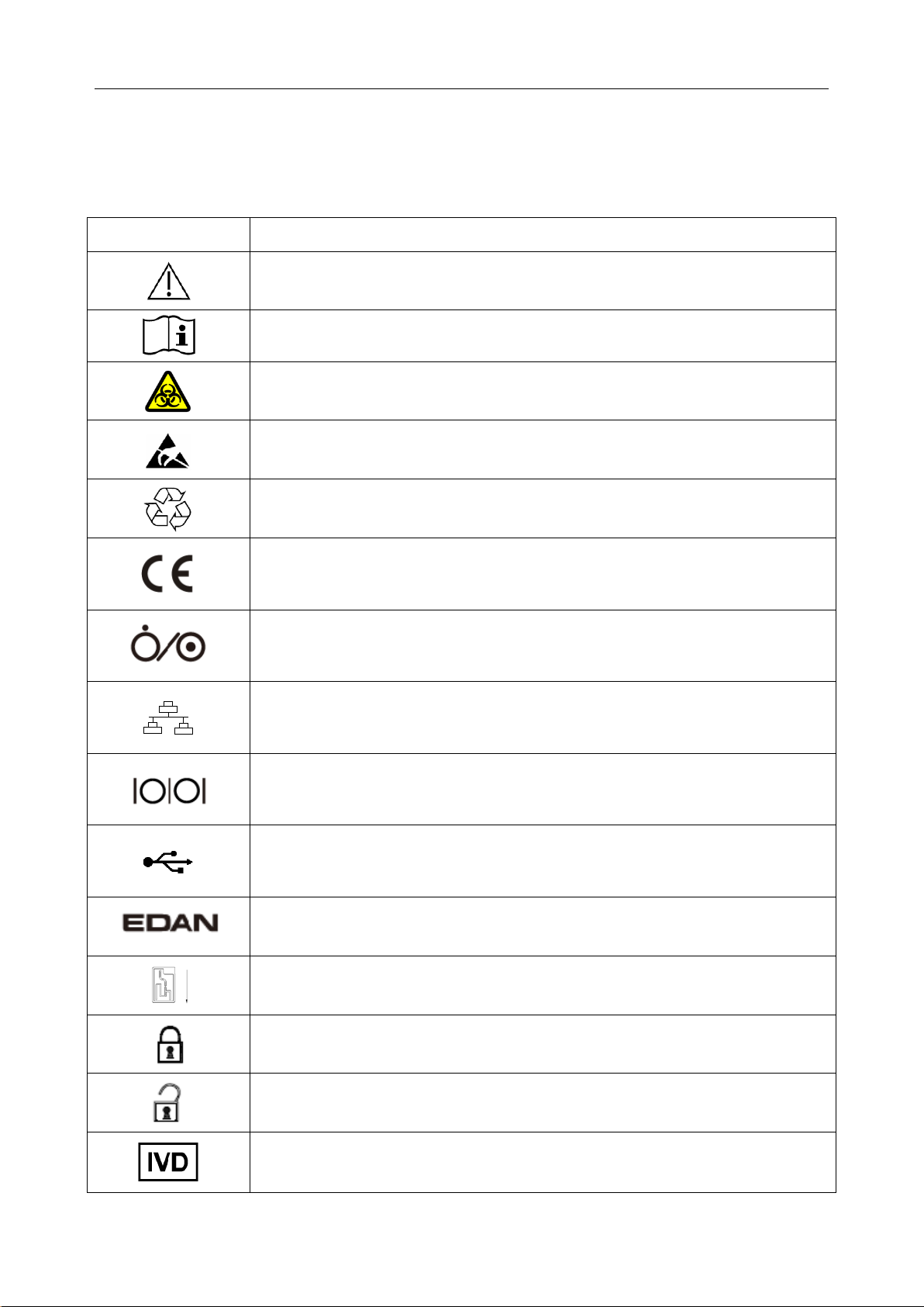
The following symbols will appear on the packaging of the system:
Symbol Description
Caution!
Consult instructions for use
Biological risks
Static electricity sensitive
Recycle
The symbol indicates that the device complies with the European Council
Directive 98/79/EEC concerning medical devices.
On/Off button
Network port
Serial port
USB (Universal Serial Bus) connection
Trademark
Test cartridge insert direction
Calibrant fluid pack chamber door is closed.
Calibrant fluid pack chamber door is open.
In vitro diagnostic device
- 6 -
Page 15
i15 Blood Gas and Chemistry Analysis System User Manual Safety Guide
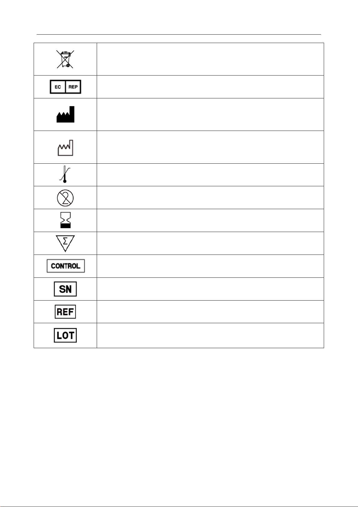
Indicates that the device should be sent to special agencies accordi n g to
local regulations for separate collection after its useful life.
Authorized representative in the European Community
Manufacturer
Date of manufacture
Temperature limitations
Do not reuse
Use by
Contains sufficient for (n) tests
Control
Serial number
Catalog number
Batch code
- 7 -
Page 16

i15 Blood Gas and Chemistry Analysis System User Manual System Overview
Chapter 2 System Overview
NOTE:
The pictures and interfaces in this manual are for reference only.
2.1 Introduction
The system is fo r in-vitro analysis of whole blood, designed to deliver quantitative results for a
panel of tests. The product consists of an analyzer incorporating a user interface with a large color
touch screen interfacing to the electronic analyzer. The user interface module contains the
analyzer CPU and all of the required el ectronic interfaces for external comm unication and data
storage. The product consists of a single-use cartridge into which the sample is introduced. The
cartridge contain s electrochemical senso rs which generat e signals related to concentration levels
in the blood. These concentration levels are displayed on the screen of the analyzer, stored in
memory, and can be transmitted by communication link or Wi-Fi to the Data Management
System (DMS).
The following tables list the parameters that can be determined by the system:
Measured Parameters:
Symbol Description
pH Negative logarithm of the hydrogen ion concentration
pCO2 Partial pressure of carbon dioxide
pO2 Partial pressure of oxygen
K+ Potassium ion concentration
Na+ Sodium ion concentration
Cl- Chloride ion concentration
Ca++ Concentration of ionized calcium
Hematocrit: the volume occupied by red blood cells in a given volume of whole
Hct
blood.
- 8 -
Page 17

i15 Blood Gas and Chemistry Analysis System User Manual System Overview
the amount of
corrected for entered patient
Calculated Parameters:
Symbol Description
+
cH
Hydrogen ion concentration
cH+ (T) Hydrogen ion concentration corrected for entered patient temperature
pH (T) pH value corrected for entered patient temperature
pCO2 (T) pCO2 corrected for entered patient temperature
pO2 (T) pO2 corrected for entered patient temperature
-
HCO
HCO
act Bicarbonate ion concentration
3
-
std Bicarbonate ion concentration normalized to a pCO2 of 40mmHg
3
BB (B) Buffer base
BE (B) Base excess (B)
BE (ecf) Base excess (ecf)
ctCO2 Total carbon dioxide
Ca++ (7.4) The ionized calcium concentration of blood normalized to pH 7.4
An approximation of the difference between measured cations and measured
AnGap
anions in the sample
tHb (est) An estimation of the hemoglobin contained in the sample
An estimation of hemoglobin oxygen saturation: a ratio of
sO2 (est)
hemoglobin bound to oxygen to the total amount of hemoglobin able to bind
oxygen
pO2 (A-a) Alveolar-arterial oxygen tension difference
Alveolar-arterial oxygen tension difference
pO2 (A-a) (T)
temperature
pO2 (a/A) Arterial-alveolar oxygen tension ratio
pO2 (a/A) (T) Arterial-alveolar oxygen tension ratio corrected for entered patient temperature
- 9 -
Page 18
i15 Blood Gas and Chemistry Analysis System User Manual System Overview
when both values are corrected for patient
System (DMS)
Respiratory index: the ratio of the alveolar-arterial blood oxygen-pressure
RI
difference to arterial pO2
Respiratory index: the ratio of the alveolar-arterial blood oxygen-pressure
RI (T)
difference to arterial pO2
temperature
pO2/FIO
The ratio of arterial pO2 to the fraction of inspired oxygen
2
The ratio of arterial pO2 to the fraction of inspired oxygen corrected for the
pO2 (T)/FIO2
entered patient temperature
Configuration: main unit, printer, scanner, and simulator.
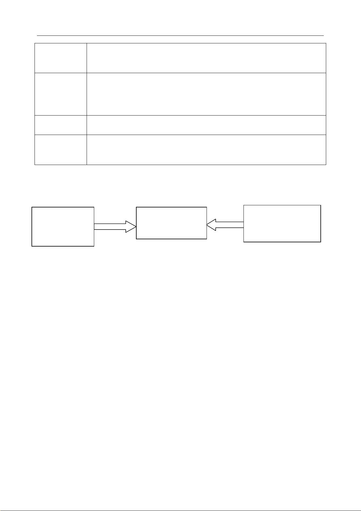
2.2 System Frame
Blood Gas and
Chemistry
Analyzer
Blood Gas and Chemistry Analyzer
Data Management
Laboratory/Hospital
Information System
(LIS/HIS)
The Blood Gas and Chemistry Analyzer is an electronic instrument which is used to analyze
whole blood samples (measuring blood gases, electrolytes, metabolites, and hematocrit). The
analyzer can:
Scan bar cod es of test cartridges, calibrant flu id packs, controls, p atient an d operator ID,
etc.
Identify the types of test cartridges.
Control the flow of fluids.
Maintain sample temperature at 37°C.
Measure the ambient barometric pressure and ambient temperature.
Measure electrical signals generated by chemical sensors and biosensors.
Analyze and display the concentrations of analytes in whole blood samples.
Transmit test results to the Data Management System (DMS).
- 10 -
Page 19

i15 Blood Gas and Chemistry Analysis System User Manual System Overview
Store all kinds of test results and data, such as patient sample results, control test results,
proficiency test results, simulator test results, etc.
Animatedly demonstrate the operating process.
Data Management System (DMS)
DMS refers to a computer which is loaded with the data management software. With the
DMS, you can:
Enter test application data.
Edit patient information, view, check and print test results.
View, check and print quality control (QC) test results.
Search for patient test results by patient name, patient ID, date and time, department, etc.
Calculate the amount of work of a physician, the results for a parameter of a patient
during a period, the test times and the fee of a parameter, and print the statistics results.
Set the following items: operator, department, sample status, printing, bar code, etc.
Backup and restore data, view logs.
View data for instrument diagnosis.
Import patient information from LIS/HIS.
Manage up to 20 analyzers simultaneously, storing test results transmitted by analyzers.
NOTE:
Sample ID should b e di fferent on analyzers connecting to the same DMS.
HIS/LIS
HIS/LIS transmits patient information to the DMS.
- 11 -
Page 20
i15 Blood Gas and Chemistry Analysis System User Manual System Overview
Lock
Port
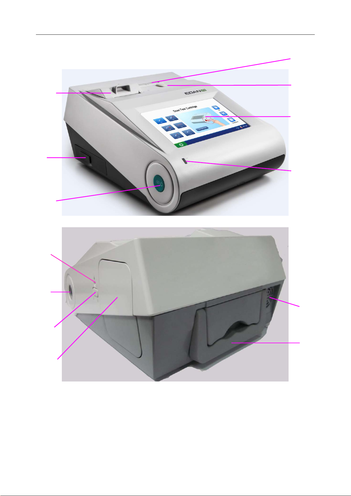
2.3 Analyzer Appearance
Thermal
Printer
I/O
Ports
On/Off
Button
Test
Cartridge
Test
Cartridge
Ejector Cap
LCD
Screen
Power
Indicator
Calibrant
Fluid Pack
Chamber
Bar Code
Scanner
Calibrant
Fluid Pack
Ejector
Calibrant
Fluid Pack
Chamber
Exhaust
Fan
Handle
- 12 -
Page 21
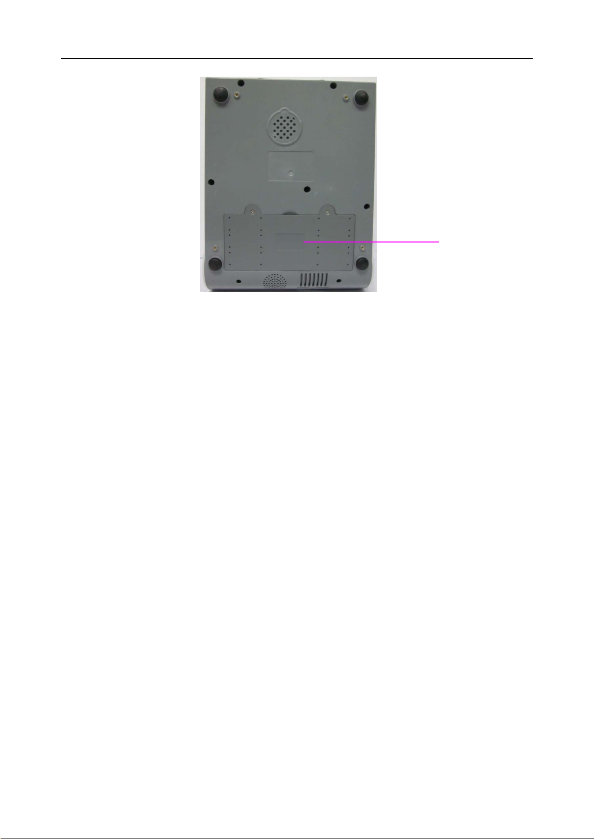
i15 Blood Gas and Chemistry Analysis System User Manual System Overview
Battery
Compartment
Figure 2-1 Analyzer Major Components
2.4 System Parts
2.4.1 Thermal Printer
The thermal print er is located at the upper left top of t he anal yzer. It can print patient sample tes t
results, quality control test results, calibration results, etc.
2.4.2 Test Cartridge
Next to the thermal printer is the test cart ridge port. A test cartridge is inserted into the analyzer
through the test cartridge port. An indicator is located inside the test cartridge port. If the test
cartridge is inserted properly, the indicator will turn green. If not, the indicator will turn red, and
the system will prompt you. If you want to perform an external electronic simulator test, you also
need to insert the simulator into the test cartridge port.
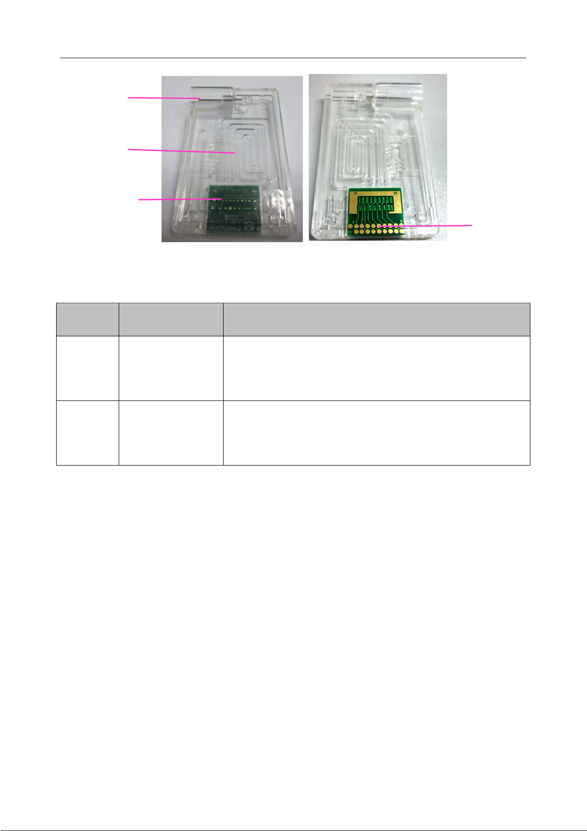
The unit-use test cartridge is intended to be used togeth er with the analyzer. The fluidic chamber
on the test cartridge is used to hold used calibrants and sample fluids. The sensors on the test
cartridge can generate el ectrical si gnals that c an b e measur ed b y th e anal yzer. The sample fillport
is used to connect the syringe/capillary tube for automatically aspirating samples. Test cartridges
are available in different configurations concerning the type of parameters reported b y them. For
details, please refer to the table below.
- 13 -
Page 22
i15 Blood Gas and Chemistry Analysis System User Manual System Overview
-
-
-
-
Chamber
Fillport
Fluidic
Sensor
Arrays
Electrical
Figure 2-2 Test Cartridge
Table 2-1 Test Cartridge Types
Contacts
Cartridge
Measured
Calculated Parameters
Type
BG8
Parameters
pH, pCO2, pO2,
Na+, K+, Cl-, Ca++,
cH+, HCO
sO2 (est), Ca
act, HCO
3
++
(7.4), AnGap, tHb (est), pO2 (A-a), pO2 (a/A),
std, BE (ecf), BE (B), BB (B), ctCO2,
3
RI, pO2/FIO2, cH+ (T), pH (T), pCO2 (T), pO2 (T),
Hct
pO2 (A-a) (T), pO2 (a/A) (T), RI (T), pO2 (T)/FIO2
cH+, HCO
act, HCO
3
std, BE (ecf), BE (B), BB (B), ctCO2,
3
sO2 (est), pO2 (A-a), pO2 (a/A), RI, pO2/FIO2, cH+ (T), pH (T),
BG3
pH, pCO2, pO2
pCO2 (T), pO2 (T), pO2 (A-a) (T), pO2 (a/A) (T), RI (T),
pO2 (T)/FIO2
Packaging
1. The type of the cartridge is labeled on the test cartridge.
2. Each test cartridge is sealed in a foil pouch containing a strip of desiccant.
3. The bar code on the foil pouch contains information su ch as the cartridge type, lot number
and expiration date, etc.
4. 25 test cartridges are packaged per box, and 4 boxes are packaged into a shipping carton.
Storage and Usage
Test cartridges should be stored at 4 - 30°C, and should be used at 10 - 31°C with the relative
humidity of 25% - 80% (non-condensing).
- 14 -
Page 23

i15 Blood Gas and Chemistry Analysis System User Manual System Overview
Disposal
The sample is contained in the test cartridge, so test cartridges should be disposed of as
biohazardous waste, complying with local regulatory guidelines.
NOTE:
If the pouch has been damaged, the test cartridge should not be used.
Only test cartridges provided by EDAN or its authorized distributors should be used.
Only test cartridges properly stored should be used.
Never reuse test cartridges.
Never touch the fillport or electrical contacts of a test cartridge.
Use test cartridges before their expiration date as labeled on the package, and use
them immediately after removing them from their pouches.
Test cartridges should be kept out of direct sunlight and heat.
The analyzer, test cartridges and the testing environment should be at the same
temperature prior to a test.
Test cartridges shoul d not be dr opp ed or stressed.
2.4.3 Power Indicator
The power indicator is on the lower left bottom of the anal yzer. During the operation you can see
one of the following:
Green Light: The analyzer is on and the power supply is normal. The analyzer can be
powered either by the rechargeable lithium battery or AC power. Or the system is off and has
been connected to AC power.
Blinking Yellow Light: The power is supplied by the rechargeable lithium battery and the
battery is low.
Yellow Light: The rechargeable lithium battery is being charged.
2.4.4 LCD Screen and Touch Screen
The activities of th e analyzer are communicated to you through the LCD screen, displaying the
analyzer activities, test results, database information, prompts, etc. You communicate with the
analyzer through the touch screen which allows you to perform tests, make select ions, ent er data,
and view information, etc.
- 15 -
Page 24
i15 Blood Gas and Chemistry Analysis System User Manual System Overview
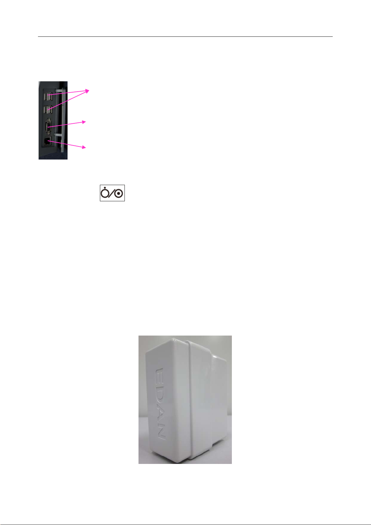
2.4.5 I/O Ports
On the left side of the analyzer are I/O ports:
USB Interfaces (4): allow you to connect your analyzer with peripherics such
as scanners, printers, etc.
Serial Port: allows engineers from the factory to perform debugging.
Network Port: allows network connection to the DMS.
2.4.6 On/Off Button
The On/Off button is on the left side of the analyzer.
2.4.7 Calibrant Fluid Pack
The calibrant fluid pack chamber is on the right side of the analyzer. You can install the calibrant
fluid pack in it for sensor calibration. The calibrant fluid pack ejector beside the door is used to
open the chamber door. On the calibrant flu id pack ejector i s a calibrant fluid pack chamber lock
to help users close the calibrant fluid chamber door securely.
A calibrant fluid pack containing calibrant solutions is intended to be used together with the
analyzer to perfo rm one-point sensor calibration. Calibrant fluid packs are av ailable for 100 and
200 sampling operations. Contact EDAN or its authorized distributors to order calibrant fluid
packs for your system.
Figure 2-3 Calibrant Fluid Pac k
- 16 -
Page 25

i15 Blood Gas and Chemistry Analysis System User Manual System Overview
Packaging
1. The calibrant fluid pack is sealed in a foil pouch filled with protective gases.
2. The bar cod e on the foil pouch contains information such as the lot number and expiration
date.
3. Each calibrant fluid pack is packaged into a box, and 6 boxes are packaged into a shippin g
carton.
Storage and Usage
Calibrant fluid packs should be stored at 2 - 8°C (avoid freezi ng) with the ambient pressure of 65
- 106.6kPa, and should be used at 10 - 31°C with the relative humidity of 25% - 80%
(non-condensing). The calibrant fluid pack expires 30 days after its installation or after exceedi n g
the labeled exp iration date, whichever comes f irst. The remaining days and usages are displayed
on the status bar at the bottom of the screen.
NOTE:
If the pouch has been damaged or there is any leakage, the calibrant fluid pack
should not be used.
Only those calibrant fluid packs provided by EDAN or its authorized distributors
should be used.
Use calibrant fluid packs before their expiration date as labeled on the package.
A calibrant fluid pack is intended for single use only. If a calibrant fluid pack is
removed from the system, it cannot be inserted into the system again.
2.4.8 Bar Code Scanner
On the same side as the calibrant fluid pack chamber is the built-in scanner for scanning bar
codes on test cartridges, calib rant fluid packs, controls, operator ID, patient ID, sample ID, etc.
The analyzer can also be connected to external scanners as mentioned in 2.4.11.
Follow the steps below to scan a bar code:
1. Press Scan Barcode or to acti vate the bar code s canner, and the scanner will emit a red
beam.
2. Align the bar code with the red beam so that the red beam covers the whole bar code.
- 17 -
Page 26

i15 Blood Gas and Chemistry Analysis System User Manual System Overview
NOTE:
The distance between the analyzer and the bar code should be 6 - 15cm.
3. If the bar code is scanne d successfully, the anal yzer will beep and automatically turn off the
scanner.
4. If the scanned data is valid, the system will display the screen for the next procedure. If t he
scanned data is invalid, a message will pop up to prompt you.
CAUTION
1. In order to avoid injury, never look into the red beam.
2. To avoid damage, never scratch the protective glasses of the scanner with hard
objects.
3. To avoid damage and injury, never strike the protective glasses of the scanner.
4. To av oid unsuccess ful scanning, clean the s canner w ith a li nt-free clot h when there is
visible dirt.
2.4.9 Exhaust Fan
The exhaust fan is located at the rear of the analyzer to prevent the analyzer from overheating.
When the analyzer temperature is over preset threshold, the fan will be automatically turned on.
NOTE:
Make sure that the vents of the analyzer are not obstructed to ensure good
ventilation.
If the exhaust fan does not run properly, please contact EDAN or its authorized
distributors for assistance.
2.4.10 Electronic Simulator
Electronic simulators are quality control devices for checking the analyzer’s ability to take
accurate measurements of voltage, current and conductivity from test cartridges.
Internal Electronic Simulator
Internal electronic simulator is self-contained in the analyzer for automatically conducting
simulator tests at the preset frequency.
- 18 -
Page 27
i15 Blood Gas and Chemistry Analysis System User Manual System Overview
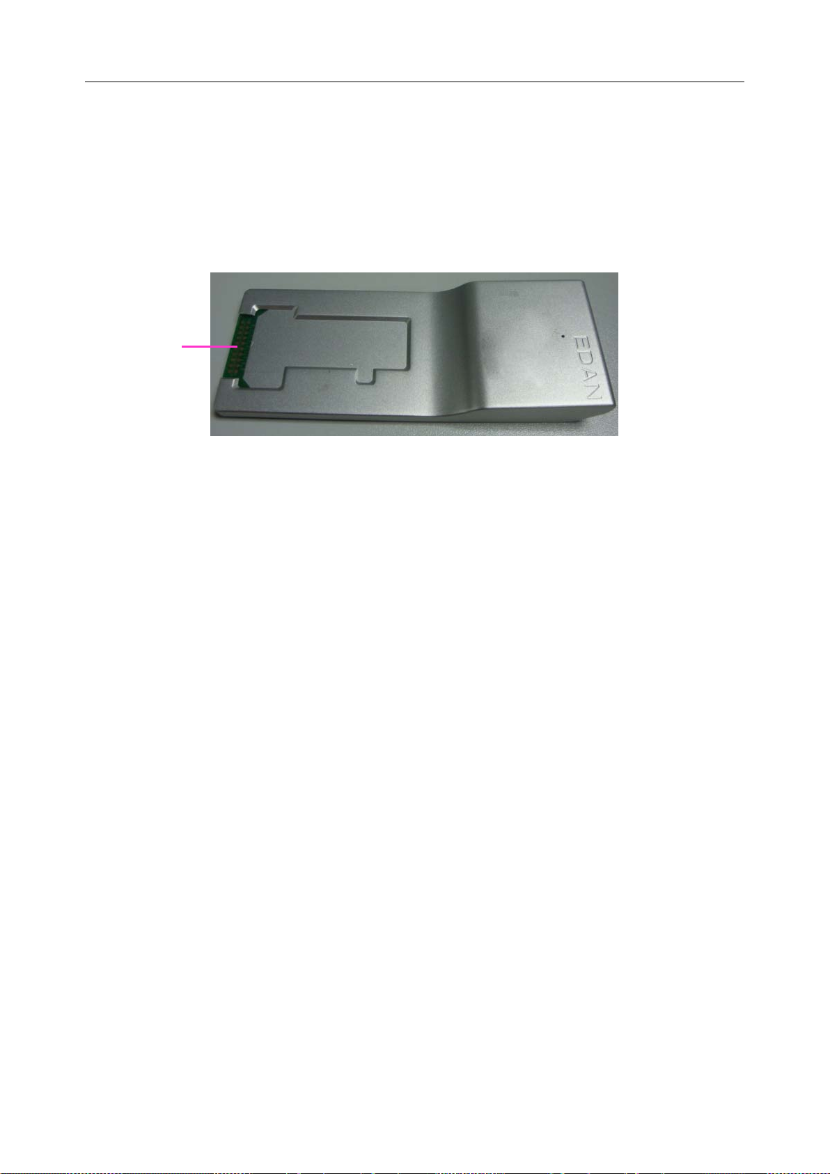
External Electronic Simulator
Users can run the external electronic simulator test according to their own needs, and EDAN
recommends that users run it every 24 hours. Each external electronic simulator is packaged
separately. When you have doubt about the reliability of test results, you can run the external
electronic simulator test to help troubleshoot.
Contact pads
Figure 2-4 External Electr onic Simulator
If the contact pads have been contaminated, please clean the external electronic simulator.
Follow the steps below to clean the external electronic simulator:
1. Moisten a lint-free cloth with 100% alcohol;
2. Wipe the external electronic simulator with the lint-free cloth.
NOTE:
Never immerse the simulator into any liquids.
The cloth should be wet but not dripping.
2.4.11 Peripherics
Only the following external scanners should be connected to the analyzer through USB ports:
Honeywell 1900.
Only the following external printers should be connected to the analyzer through USB ports: H P
LaserJet P401DN, and HP LaserJet P1606DN.
NOTE:
Only peripherics recommended by EDAN should be connected to the analyzer.
When connecting a Honeywell 1900 scanner to the analyzer, the scanner should be
set.
- 19 -
Page 28

i15 Blood Gas and Chemistry Analysis System User Manual System Overview
2.5 Configuration
2.5.1 Standard Configuration
i15 analyzer
1 power cable
1 power adaptor
4 printer paper
1 rechargeable lithium battery
1 user manual
1 warranty card
2 packing lists
2.5.2 Options
Test cartridges
Calibrant fluid pack
External electronic simulator
Capillary adaptor
Controls
Data management system software
Honeywell 1900 scanner
- 20 -
Page 29

i15 Blood Gas and Chemis t r y Analysis System User Manual Installation Guide
Chapter 3 Installation Guide
3.1 Unpacking Inspection
Visually examine the package prior to unpacking. If there are any signs of mishandling or damage,
contact the carri er to claim for damage. Aft er unpacki ng the devic e, custom ers should follow the
PACKING LIST to check the product carefully and to make sure no damage occurred during
transportation. Then, install the device according to the installation requirements and procedures.
If there is any problem, contact the manufacturer or its authorized distributors immediately.
WARNING
DO NOT use the analyzer if it is damaged or defective.
NOTE:
Keep the package for futur e transportation or for storage.
3.2 Installation Requirements
3.2.1 Environmental Requirements
Location is of great importance for the smooth running of your analyzer. Prior to installing the
analyzer, choose a site that meets the following requirements:
Convenient for the analyzer to be connected to a grounded elect rical receptacle i n case it is
powered by AC power.
Keep the anal yzer away from direct exposure to strong sunlight.
Ambient Temperature between 10°C and 31°C.
Relative Humidity of 25% - 80% (non-condensing).
Ambient Pressure within 70 - 106.6kP (525 - 800mmHg).
Placed onto a clean and flat surface with good ventilation.
Keep the analyzer away from equipment with strong electric field and strong magnetic field.
Keep the analyzer away from explosive gases or vapors.
NOTE:
The requirements above also apply when your analyzer is powered by a rechargeable
lithium battery.
- 21 -
Page 30

i15 Blood Gas and Chemis t r y Analysis System User Manual Installation Guide
3.2.2 Power Requirements
The analyzer needs to be connected to a grounded electrical outlet with the voltage between
100±10% VAC - 240±10% VAC and the frequency of 50/60Hz.
3.3 Setting Up
Now you can prepare your analyzer for operation.
First, please place the analyzer on a secure table surface with environments that meet the
requirements as described in section 3.2.
3.3.1 Connecting to AC Power
1. Insert the power adaptor into the power connector on the analyzer.
2. Plug the power cord into the power adaptor.
3. Plug the power cord into a grounded electrical outlet.
NOTE:
Make sure the power requirements as described in 3.2.2 are met.
To avoid the anal yz er and other elec tro nic dev ic es being damag ed by elec tric al pow er
spikes, a surge protector is recommended.
3.3.2 Installing the Battery
WARNING
Switch off the analyzer and unplug it before installing or removing the battery.
If the analyzer is powered by a rechargeable lithium battery, please install the battery first.
Battery Installation
Follow the steps below to install the battery:
1. Turn off the analyzer, disconnect the power supply, and remove the power adaptor and other
connecting cables.
2. Place the analyzer upside down on a flat surface covered with cloth or another type of
protecting pad.
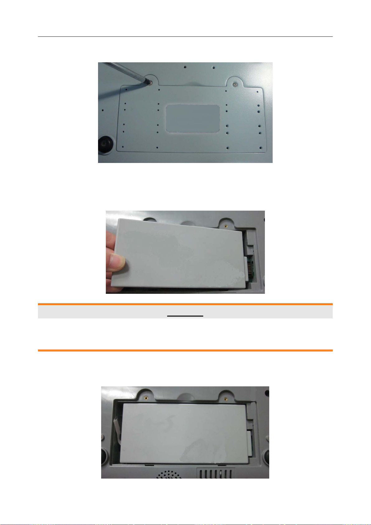
3. Remove the screws of the battery compartment using a cross-head screw driver, and then
- 22 -
Page 31
i15 Blood Gas and Chemis t r y Analysis System User Manual Installation Guide
remove the battery compartment cover.
4. Take the battery out from its package and put it into the compartment. Make sure the battery
connector is on the right and the battery label faces down. Install the battery into the
compartment.
WARNING
Do not touch t he bat t ery connector with fingers or metallic materials, to avoid the hazards
posed by the short-circuit to you and the battery.
5. Arrange the battery flat in the compartment, and push the strip at the end of the battery into
the gap.
- 23 -
Page 32

i15 Blood Gas and Chemis t r y Analysis System User Manual Installation Guide
6. Shut the battery compartment cover and secure it with the screws.
Battery Removal
Remove the battery in reverse order. You can pull the strip at the end to take the battery out from
the compartment.
NOTE:
The battery needs to be charged pr i or to using it.
Only those batteries supplied by EDAN or its authorized distributors should be used
with the analyzer.
When the analyzer is powered by the battery and the battery is low, the system will
prompt you to connect the an al y z er to an external power outlet. At the same time, the
battery indicator icon on the status bar at the bottom of the screen will also blink.
The battery will automatically be charged whenever the analyzer is connected to an
electrical outlet.
3.3.3 Installing the Printer Paper
The analyzer utili zes rolled thermal paper with the width of 50mm. When the printer paper runs
out during the printing or is not loaded, the warning message “Paper?” will appear on the screen.
Then you should load or replace the printer paper immediatel y.
Procedures for Loading Rolled Thermal Paper
1. Open the casing.
2. Gently pla ce the p aper in the paper tra y with the outside of the pap er facing the thermal print
head.
3. Pull about 2 cm of paper out and shut the printer casing.
- 24 -
Page 33

i15 Blood Gas and Chemis t r y Analysis System User Manual Installation Guide
Procedures for Replacing Rolled Thermal Paper
The procedures for replacing rolled thermal paper is almost the sam e as loading rolled thermal
paper, except that you need to remove the remained rolled thermal paper prior to step 2.
CAUTION
1. Only use the printer paper provided by EDAN or its authorized distributors, otherwise
the printer may be damag ed. This kind o f damage is not covered by warranty.
2. Do not touch the thermosensitive print head or the paper sensor by hand, in case
they are damaged by static electricity.
NOTE:
Unless when replacing paper or troubleshooting, do not leave the printer casing open.
3.3.4 Turning On/Off the Analyzer
NOTE:
Make sure that all the cables are securely connected before you turn on the analyzer.
Turn On the Analyzer
Press the On/Off button on the left side of the analyzer to turn it on.
Turn Off the Analyzer
1. Press on the bottom left of the screen, the following message will pop up:
Figure 3-1 Turn Off Analy zer
2. Press , and press OK in the pop up dialog box.
NOTE:
Never turn off the system when it is performing tests or printing data.
- 25 -
Page 34

i15 Blood Gas and Chemis t r y Analysis System User Manual Installation Guide
3.3.5 User Login and Logout
User Login
1. Press the On/Off button on the left hand side of the analyzer to turn it on.
2. Enter the user name and password manually, and press .
To en ter the user name w it h t he b ar code s canner, press first, and then scan the user
name bar code.
Figure 3-2 Enter User Name a nd Password
User Logout
1. Press on the bottom left of the screen, the following message will pop up:
Figure 3-3 User Logout
2. Press , and press OK in the pop up dialog box. The system will go to the User
Login screen. Enter a user name and password to change users.
NOTE:
Never log out of the system when it is performing tests or printing data.
- 26 -
Page 35

i15 Blood Gas and Chemis t r y Analysis System User Manual Installation Guide
3.3.6 Setting the Date and Time
1. On the Main screen, press to access the System Setup screen.
2. Press to access the Date & Language Setup screen.
3. Select the desired date and time, and press OK in the pop up dialogue box.
4. Press OK to accept the changes.
5. Press Return to return to the Main screen.
CAUTION
1. Make sure the current date and time of the system are correct, or it may cause
misdiagnosis.
2. Changing date and time directly affects date and time saved with each test data.
3.4.7 Viewing Training Videos
The system has training videos for guiding your operations.
Follow the steps below to view training videos:
1. Press on the bottom right of the screen to access the Help screen.
Figure 3-4 Help Screen
2. Press to view the video for replacing a calibrant fluid pack.
3. Press to view the video for analyzing syringe samples.
4. Press to view the video for analyzing ampoule samples.
- 27 -
Page 36

i15 Blood Gas and Chemis t r y Analysis System User Manual Installation Guide
5. Press to view the video for analyzing capillary samples.
6. Press Return to go back to the Main screen.
3.4.8 Replacing a Calibrant Fluid Pack
WARNING
1. The replacement of a calibrant fluid pack should be performed only when the
analyzer is on.
2. A calibrant fluid pack is intended for single use only. If a calibrant fluid pack is
removed from the system, it can not be inserted into the system again.
Follow the steps below to replace a calibrant fluid pack:
1. Examine the expiration date on the package of a calibrant fluid pack to ensure it has not
expired.
2. Remove the calibrant fluid pack from its package, and equilibrate it to room temperature.
The calibrant fluid pack needs to stand at room temperature for at least 24 hours.
3. Wipe any moisture from the foil pouch with a dry clean cloth.
4. On the Main screen, press to go to the System Setup screen.
5. Press . The system will go to the screen below:
Figure 3-5 Open Chamber Door
6. Open the foil pouch, and remove the calibrant fluid pack from it.
- 28 -
Page 37

i15 Blood Gas and Chemis t r y Analysis System User Manual Installation Guide
NOTE:
Avoid tearing the bar code on the foil pouch.
7. Remove the cali brant fluid pack cap, and remove the key b y pushing it with you r finger in
the direction as shown by the arrow in the picture below.
Key
Valve
NOTE:
Avoid pushing the valve when removing the key.
8. Unlock the calibrant fluid pack chamber lock with the key, and then pull the calibrant fluid
pack ejector to open the calibrant fluid pack chamber door.
9. Remove the used calibrant fluid pack from the system. The system will go to the screen for
the next procedure, and the scanner will be turned on automatically.
Figure 3-6 Remove Old Calibrant Fluid Pack
- 29 -
Page 38

i15 Blood Gas and Chemis t r y Analysis System User Manual Installation Guide
10. Scan the bar code on the new calibrant fluid pack foil pouch with the bar code scanner.
If the bar code is scanned successfully, the system will beep and the scann er wi ll be turned off
automatically. If the scanned data is valid, the system will display the screen for the next
procedure. If the scanned data is invalid, a message will pop up to prompt you.
If the scanner is turned off automatically, press first, and then scan the bar code.
Figure 3-7 Scan Bar Code
11. Insert the new calibrant fluid pack into its chamber, and push it gently to make sure that it
clicks into place. The system will go to the screen for the next procedure.
Figure 3-8 Install Calibrant Fluid Pack
- 30 -
Page 39

i15 Blood Gas and Chemis t r y Analysis System User Manual Installation Guide
12. Close the chamber door.
Figure 3-9 Close Chamber Door
13. Lock the calibrant fluid pack chamber lock to close the chamber door securely.
14. Press OK in the pop up message. The system will then go to the Main screen.
Figure 3-10 Replacement Success
NOTE:
Always follow the proper procedures to replace a calibrant fluid pack, or else the
system will not run smoothly, and the following message will pop up:
Figure 3-11 Calibrant Flu id Pack Improper Removal
- 31 -
Page 40

i15 Blood Gas and Chemis t r y Analysis System User Manual Installation Guide
If the bar code is not that of a calibrant fluid pack, the foll owing message will pop up:
Figure 3-12 Unidentified Bar Code
If the bar code is that of a used calibr ant fluid pack or that of an expired calibrant fluid
pack, the following message will pop up:
Figure 3-13 Calibrant Flu id Pack Can Not be Used
3.3.9 DEMO Test
The system can demonstrate the sample testing processes through animation. Follow the steps
below to perform a DEMO test:
1. Logout of the system. The system will access the User Login screen.
2. Enter demo in both th e user name and password fields, and then press . The system will
go to the following screen:
- 32 -
Page 41

i15 Blood Gas and Chemis t r y Analysis System User Manual Installation Guide
Figure 3-14 DEMO Test Screen 1
3. Press Scan Barcode.
4. Press Next.
Figure 3-15 DEMO Test Screen 2
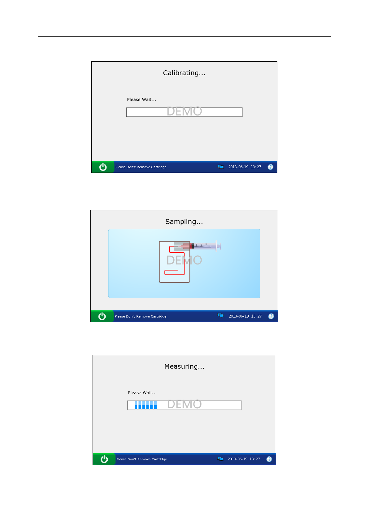
5. The system simulates aspirating calibrant.
Figure 3-16 DEMO Test Screen 3
- 33 -
Page 42
i15 Blood Gas and Chemis t r y Analysis System User Manual Installation Guide
6. The system simulates calibration.
Figure 3-17 DEMO Test Screen 4
7. The system simulates sampling.
8. The system simulates testing.
Figure 3-18 DEMO Test Screen 5
Figure 3-19 DEMO Test Screen 6
- 34 -
Page 43
i15 Blood Gas and Chemis t r y Analysis System User Manual Installation Guide
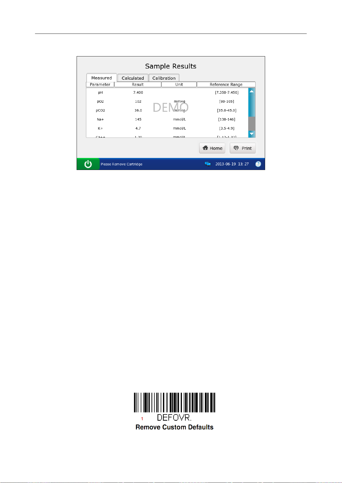
9. The system simulates displaying test results.
Figure 3-20 DEMO Test Screen 7
10. Press Home to return.
11. Follow the steps as described in 3.3.5 to logout of the system.
3.3.10 Connecting Peripherics
Connect peripherics with the system through USB ports, and make sure that th e system m eets the
requirements in IEC60601-1-1.
NOTE:
Only peripherics recommended by EDAN should be connected.
Make sure that the whole system meets the requirements in IEC60601-1-1.
Follow the steps below to set a Honeywell 1900 scanner:
1. Connect a Honeywell 1900 scanner to the analyzer through a USB port.
2. Hold the scanner with your right hand, and trigger the scanner with your forefinger.
3. Scan the following bar codes in sequence.
- 35 -
Page 44

i15 Blood Gas and Chemis t r y Analysis System User Manual Installation Guide
4. Use the scann er to s can a b ar cod e of a test cartridge. If the bar code is successfully scanned,
the scanner is successfully set.
- 36 -
Page 45

i15 Blood Gas and Chemistry Analysis System User Manual Setup
Chapter 4 Setup
The system can be configured according to your clinical needs. The setup can onl y be done by
authorized operators. You can perform the following setup with the Setup menu:
Printer Setup
Network Setup
Date & Language Setup
Backlight & Volume Setup
QC Lockout Setup
Patient Information Setup
Reference Ranges Setup
Units Setup
Correlation Factors Setup
Hct Setup
NOTE:
Only administrators, service engineers and engineers from the manufacturer can get
access to this function.
The system will remember all the changes in setup even after the system is turned
off.
4.1 Getting into the Setup Screen
1. Press the On/Off button on the left hand side of the analyzer to turn it on.
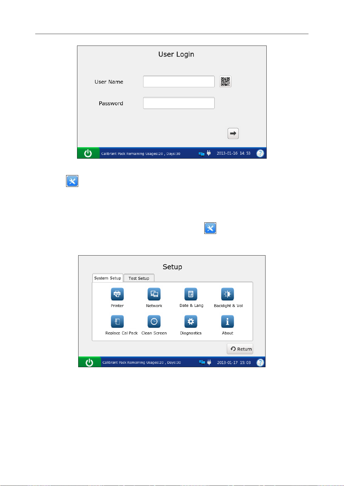
2. Enter the user name and password manually, and press .
To enter the user name with the bar code scanner, press first, and then scan the user
name bar code.
- 37 -
Page 46
i15 Blood Gas and Chemistry Analysis System User Manual Setup
Figure 4-1 Enter User Name a nd Password
3. Press on the Main screen, and the system will go to the Setup screen.
4.2 System Setup
The system displays the System Setup screen after pressing on the Main screen by default.
If you are now on the Test Setup screen, press System Setup to get to the System Setup screen.
Figure 4-2 Setup-System Setup Screen
You can perform the following actions:
- 38 -
Page 47
i15 Blood Gas and Chemistry Analysis System User Manual Setup
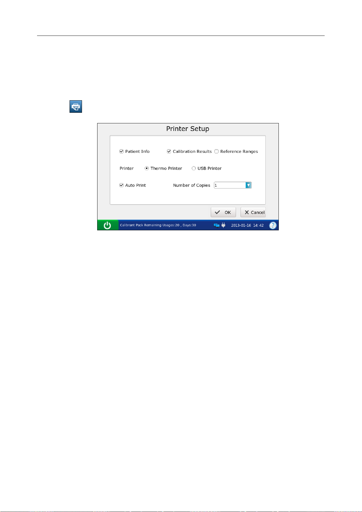
4.2.1 Printer Setup
This menu lets you configure the printer that the system uses, what are printed in reports, and the
number of copies it prints.
Follow the steps below to set the printer:
1. Press to access the Printer Setup screen.
Figure 4-3 Printer Setup Screen
2. On the Printer Setup screen, you can:
Select whether to print patient information. The mark √ will appear if Patient Info is
selected, and the default is to print patient information.
Select whether to print calibration results. The mark √ will appear if Calibration Results is
selected, and the default is to print them.
Select whether to print reference ranges. The mark √ will appear if Reference Ranges is
selected, and the default is to not print them. If Reference Ranges is select ed, t he ref erence
ranges will be contained in the patient sample report, and the acceptable ranges will be
contained in the control test report.
Select t he printer t o be used. Ther e are two options: Thermo Printer an d USB Printer. The
default is Thermo Printer.
Select whether to turn on Auto Print. The mark √ will appear if Auto Print is turned on, and
the default is to turn on Auto Print.
Select the number of copies. There are two options: 1 and 2. The default is 1.
3. Press OK to accept the changes, and the system will return to the System Setup screen.
- 39 -
Page 48

i15 Blood Gas and Chemistry Analysis System User Manual Setup
4.2.2 Network Setup
This menu allows you to configure the communication methods, transmitting methods, and the
manner that the analyzer is connected to the network.
Follow the directions below to configure the network:
1. Press to access the Network Setup screen.
2. There are three tabs: Communication, Network, and WIFI.
Network Setup
1) Press Communication to go to the Communication Setup screen.
Figure 4-4 Network – Communication Setup Screen
2) On the Communication Setup screen, you can:
Select the communication protocols. There is only one option: POCT 1-A.
Select whether to transmit patient sample results automatically. There are two
options: On and Off. If your selection is On, patient sample results will be
transmitted automatically after each measurement. The default is On.
Select the communication methods. There are two options: Network and WIFI.
The default is Network.
Enter the IP address of the DMS to which your analyzer is connected.
3) Press OK to accept the changes, and the system will return to the System Setup
screen.
- 40 -
Page 49

i15 Blood Gas and Chemistry Analysis System User Manual Setup
Network Setup
1) Press Network to access the Network-Network Setup screen.
Figure 4-5 Network – Network Setup Screen
2) Select the way that the analyzer is connected to the network. Ther e are two options:
DHCP (dynamic host configuration protocol) and Static IP addresses. The Default i s
DHCP. If the latter one is select ed, the following information should be entered: IP
address, the default gateway, and the network mask.
NOTE:
The static IP addr ess s hould be i n t he s ame a rea n etw ork wi th the IP ad dress
of the DMS.
IP addresses for analyzers connected to the same DMS should be different.
Only when both the DMS and the analyzer have been connected to network
successfully can the analyzer transmit data to the DMS.
3) Press OK to accept the changes, and the system will return to the System Setup
screen.
WIFI Connection
1) Press WIFI to access the WIFI Setup screen.
Figure 4-6 Network - WIFI Setup Screen
- 41 -
Page 50

i15 Blood Gas and Chemistry Analysis System User Manual Setup
2) Press Search WIFI, the system will automatically search networks and display
them. If the system displays Lock for the network password, it is necessar y to enter
its password to connect the system to it.
3) Press the network you want to connect, and press Connect WIFI.
NOTE:
The selected network should be in the same area network with that of the DMS.
4) Press Return, and the system will return to the System Setup screen.
4.2.3 Date & Language Setup
With this menu you can set the time and date, the date format, and the l angua ge the an al yzer use s
for displays and printouts.
Follow the instructions below to set the date and language:
1. Press to go to the Date & Language Setup screen.
Figure 4-7 Date & Langua ge Setup Screen
2. On the Date & Language Setup screen, you can:
Change the time and date of the system.
Select the d ate format. There are t hree formats: MM-DD-YYYY, YYYY-MM-DD and
DD-MM-YYYY. The default is YYYY-MM-DD.
Select the l anguage for displays and printouts. The options are: Simplified Chinese and
English. The default language is English.
3. Press OK to accept the changes, and the system will return to the System Setup screen.
- 42 -
Page 51

i15 Blood Gas and Chemistry Analysis System User Manual Setup
4.2.4 Backlight & Volume Setup
This menu allows you to define the idle time after which the backlight will be automatically
turned off, the brightness of the backlight, the key tones and the volume.
1. Press to go to the Backlight & Volume Setup screen.
Figure 4-8 Backlight & Volume Setup Screen
2. On the Backlight Setup screen, you can:
Adjust the brightness of the backlight with the slider.
Select the idle time after which the backlight will be automatically turned off. The
options are: never, 10 seconds, 1 minute, 3 minutes and 5 minutes. The default setting is
1 minute.
NOTE:
The system will enter standby mode after the backlight is turned off. Press the LCD
screen to resume normal operation mode.
Set the key tones. There are two op ti on s: On and Off. If On is sel ected , and the volume is
not mute, the system will beep after each effective press.
Select the volume of the system. There are four options: High, Medium, Low and Mute.
The default is Medium.
3. Press OK to accept the changes, and the system will return to the System Setup screen.
4.2.5 Diagnostics
This menu lets you diagnose some modules of the analyzer to check its operation. It helps to
troubleshoot.
- 43 -
Page 52

i15 Blood Gas and Chemistry Analysis System User Manual Setup
NOTE:
Only service engineers and engineers from the manufacturer can perform this action.
4.2.6 About the Analyzer
The system contains information about your analyzer which makes it convenient for you to know
more about your analyzer and call for technical assistance if necessary.
1. Press to go to the About screen.
Figure 4-9 About Screen
2. View the information on the screen.
3. Press Return to get access to the System Setup screen.
4.3 Test Setup
Press Test Setup on the Setup screen to access the Test Setup screen, and then you can perform
the following operations:
Figure 4-10 Setup – Test Setup Screen
- 44 -
Page 53

i15 Blood Gas and Chemistry Analysis System User Manual Setup
4.3.1 QC Lock out Setup
This menu allows you to configure QC lockout. If QC lockout function is enabled, the system
will not report test results for those parameters that have failed quality control tests, and the
results for these parameters will be flagged with xxx. If QC lockout function is disabled, the
system will report test results for those parameters that have failed qualit y control tests, and the
test results for these parameters will be flagged with ***. The default setting is enabling QC
Lockout function.
Follow the procedures below to set QC Lockout:
1. Press to go to the QC Lockout Setup screen.
Figure 4-11 QC Lockout Setup Screen
2. Select whether to enable QC Lockout function. √ will appear if QC Lockout function is
enabled.
3. Press OK to accept the changes, and the system will return to the Test Setup screen.
4.3.2 Patient Info r mation Setup
This menu allows you to select which parameters will be displayed on the Edit Patient
Information screen during each patien t sample test . The default displayed parameters are patient
ID, temperature, FIO2 and operator ID. The table below lists the parameters for patient
information.
- 45 -
Page 54

i15 Blood Gas and Chemistry Analysis System User Manual Setup
Table 4-1 Patient Information
Parameter Range Resolution Unit
Patient ID 1 - 16 digits N/A N/A
Operator ID 1 - 16 digits N/A N/A
Sample ID 1 - 16 digits N/A N/A
14.0 – 44.0 0.1 °C
Temperature
57.2 – 111.2 0.1 ℉
Sex Male, Female, / N/A N/A
1.0 – 26.0 0.1 g/dL
tHb (Total
10 - 260 1 mg/dL
hemoglobin)
0.6 – 16.1 0.1 mmol/L
0.21 - 1.00 0.01 x.xx
FIO2
21 - 100 1 %
MCHC (Mean
corpuscular
29.0 - 37.0 0.1 g/dL
hemoglobin
concentration)
290 - 370 1 g/L
RQ (respiratory
0.70 - 2.00 0.01 x.xx
quotient)
Hemoglobin
Adult, Children, Newborn N/A N/A
type
LR/RR/LB/RB/LF/RF/Cord/Scalp/LHF/
RHF/LH/RH/AIC, PA Catheter,
CPB or Other, where:
LR=Left Radial
RR= Right Radial
LB= Left Brachial
RB= Right Brachial
LF= Left Femoral
Puncture site
RF= Right Femoral
N/A N/A
LHF= Left Hand Finger
RHF= Right Hand Finger
LH= Left Heel
RH= Right Heel
AIC= Arterial Indwelling Catheter
CPB= Cardiopulmonary Bypass
PA Catheter= PA Catheter
Other= Other
Bypass Pump Off / Pump On N/A N/A
Rm air, Mask, T-P, NC, Vent, Bag, Hood or
O2 mode
Other, where:
N/A N/A
Rm Air=Room Air
- 46 -
Page 55

i15 Blood Gas and Chemistry Analysis System User Manual Setup
Mask= Mask
T-P= T-Piece
NC= Nasal Cannula
Vent= Ventilator
Bag= Bag (manual resuscit at io n)
Hood= Hood
Other= Other
I/E Ratio 0.2 - 9.9/0.2 - 9.9 0.1 x.xx
No, SIMV, PSV, PCV, CMV/AC, CPAP,
PCIVR, or BIPAP, where:
No= None
SIMV= Synchronized Intermittent Mandatory
Ventilation
PSV= Pressure Support Ventilation
Vent mode
N/A N/A
PCV= Pressure Control Ventilation
CMV/AC= Controlled Mechanical Ventilation/
Assist Control
CPAP= Continuous Positive Airway Pressure
PCIVR= Pressure Control Inverse Ratio
BIPAP= Bi-Level Positive Airway Pressure
Pplat (Plateau
0 - 100 1 cmH2O
Pressure)
MVol (Minute
0 - 120 1 Lpm
Volume)
PIP (Peak
Inspiratory
0 - 140 1 cmH2O
Pressure)
Liter Flow 0 - 300 1 Lpm
TVol (Tidal
0 - 4000 1 mL/kg
Volume)
PS (Pressure
0 - 99.9 0.1 cmH2O
Support)
PEEP (Positive
End Expiratory
0 - 50 1 cmH2O
Pressure)
Rate 0 - 155 1 Bpm
CPAP
(Continuous
0 - 50 1 cmH2O
Positive Airway
Pressure)
Bi-Level
0.2 - 9.9/0.2 - 9.9 0.1 x.xx
Pressure
- 47 -
Page 56

i15 Blood Gas and Chemistry Analysis System User Manual Setup
NOTE:
There is no barometric pressure item in patient information. If the barometric
pressure sensor malfunctions, the system will not report results for the parameters
related to oxygen.
The selected items will be printed out in patient sample reports if Patient Info is
selected in section 4.2.1 Printer Setup.
Follow the instructions below to select which patient information is required:
1. Press to get access to the Patient Information Setup screen.
2. Press Patient Info 1, and select the desired parameters. √ indicates the parameter is selected.
Figure 4-12 Patient Inform at ion 1 Screen
3. Press Patient Info 2, and select the desired parameters. √ indicates the parameter is selected.
Figure 4-13 Patient Inform at ion 2 Screen
NOTE:
Select All to select all the parameters at each screen.
4. Press OK to accept the changes, and the system will return to the Test Setup screen.
- 48 -
Page 57

i15 Blood Gas and Chemistry Analysis System User Manual Setup
4.3.3 Reference Ranges Setup
With this menu you can set the reference range for each measured parameter. There are three
options: Reference Range 1, Reference Range 2, and Reference Range 3. The default is
Reference Range 1. A result that is out of the reference range will be flagged with an up/down
arrow. Reference ranges are factory set to be the measurement ranges for each measured
parameter. Values outside reference ranges are not flagged with an up/down arrow. Therefore
reference ranges must be set according to internal procedures at your individual institution.
Because refer ence r an ges ma y vary with demographic factors such as a ge, gender and h eri tage, it
is recommended that reference ranges be set according to the population being tested.
Follow the instructions below to set the reference ranges:
1. Press to access the Reference Ranges Setup screen.
Figure 4-14 Reference Ranges Setup Screen
2. Select the desired reference range, and edit the limits for those parameters you want to
change.
3. Press OK to accept the changes, and the system will return to the Test Setup screen.
NOTE:
If unacceptable values are entered, the system will display the correct range.
The limits entered will be saved in the system even after the system is shut down.
- 49 -
Page 58
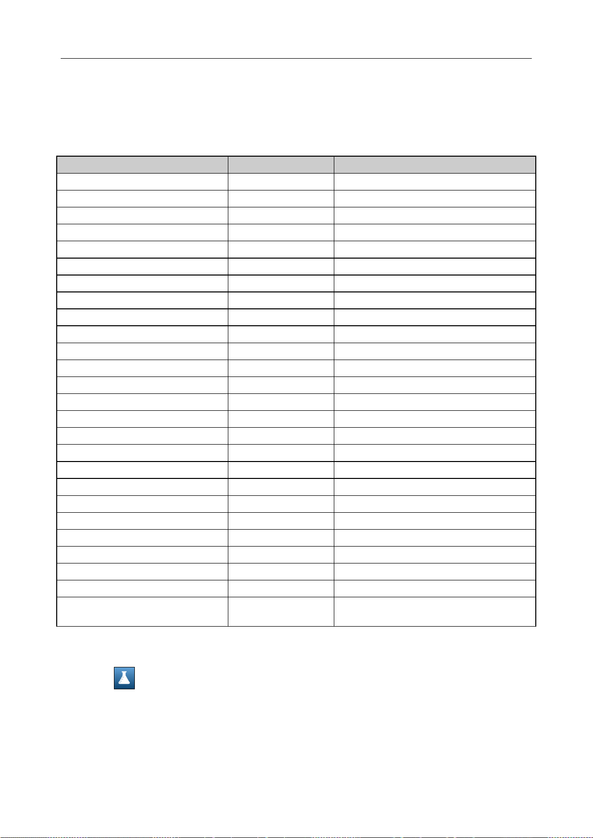
i15 Blood Gas and Chemistry Analysis System User Manual Setup
4.3.4 Units Setup
This function allows you to select the units for measured parameters, calc ulated parameters and
parameters of patient information.
Table 4-2 Units for Parameters
Parameter Default Unit Alternate Units
Ca++ mmol/L mg/dL
pCO2 mmHg kPa
pO2 mmHg kPa
Glu mmol/L mg/dL
Lac mmol/L mg/dL
Hct % x.xx
Cre μmol/L mg/dL
BUN mmol/L mg/dL
tHb(est) g/dL g/L,mmol/L
sO2(est) % x.xx
pO2(A-a) mmHg kPa
pO2(a/A) x.xx %
RI x.xx %
pO2/FIO2 mmHg mmHg/%, kPa, kPa/%
Ca++(7.4) mmol/L mg/dL
pCO2(T) mmHg kPa
pO2(T) mmHg kPa
pO2(A-a)(T) mmHg kPa
pO2(a/A)(T) x.xx %
RI(T) x.xx %
pO2(T)/FIO2 mmHg mmHg/%, kPa, kPa/%
Temperature °C ℉
FIO2 x.xx %
tHb g/dL g/L, mmol/L
MCHC g/dL g/L
Baro/Partial Pressure mmHg kPa
Follow the directions below to select the desired units for the parameters:
1. Press to get access to the Units Setup screen.
2. Press Units 1, and select the desired units for the parameters whose units you want to
change.
- 50 -
Page 59
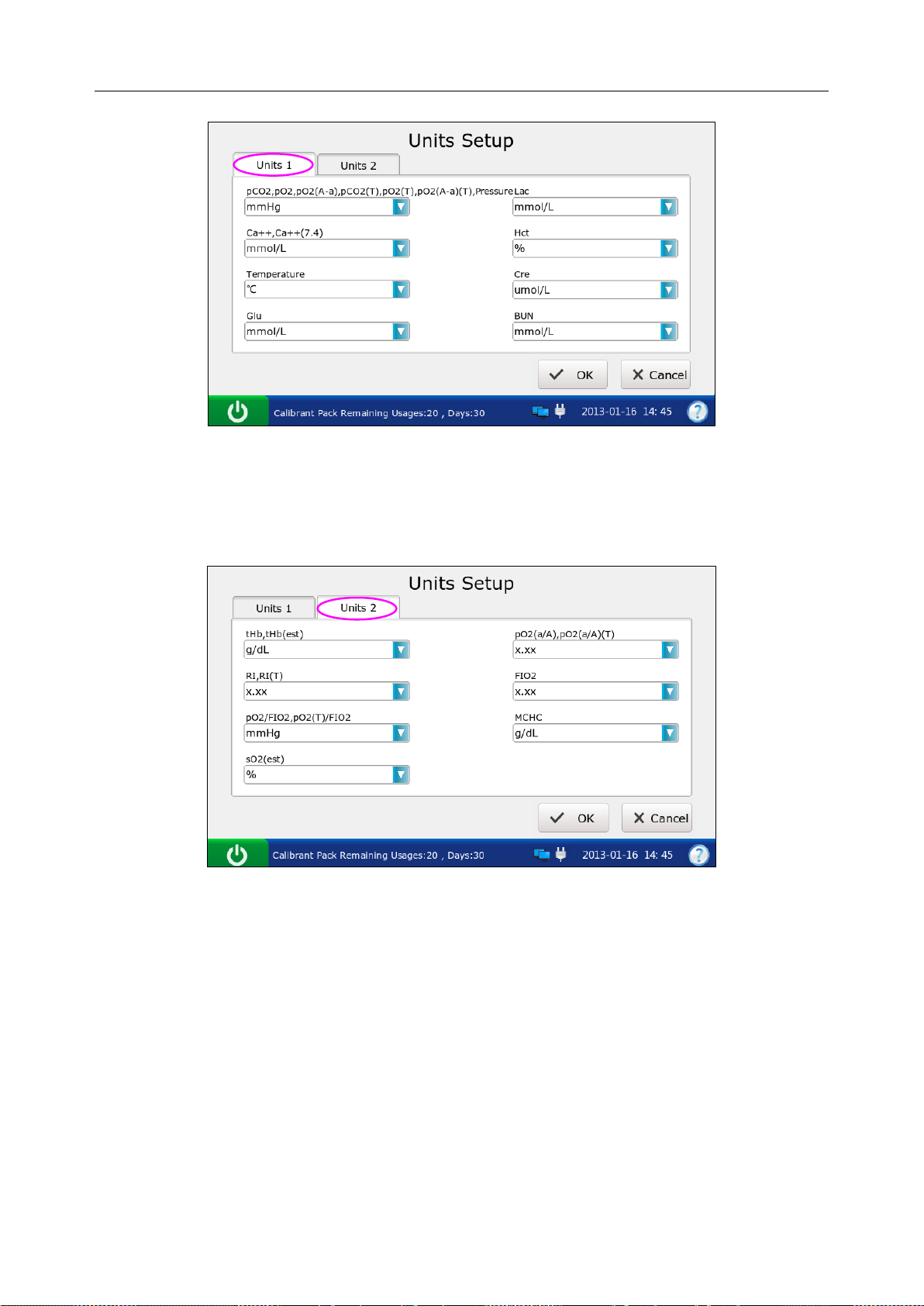
i15 Blood Gas and Chemistry Analysis System User Manual Setup
Figure 4-15 Units Setup 1 Screen
3. Press Units 2, and select the desired units for the parameters whose units you want to
change.
Figure 4-16 Units Setup 2 Screen
4. Press OK to accept the changes, and the system will return to the Test Setup screen.
NOTE:
The results stored in the system are automatically converted to match new units.
- 51 -
Page 60
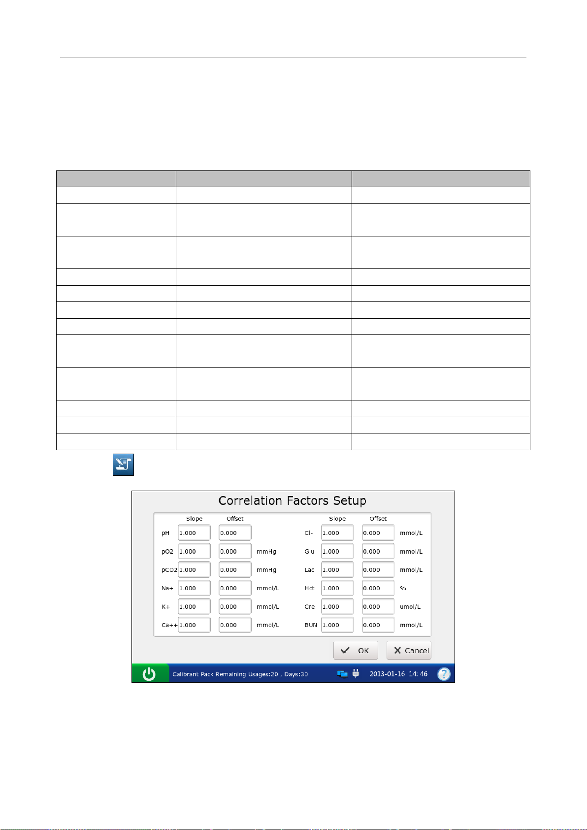
i15 Blood Gas and Chemistry Analysis System User Manual Setup
4.3.5 Correlation Factors Setup
Correlation factors allow you to correlate results obtained from the system to results obtained
from another system. The ranges for the slope and offset of each parameter are listed in table 4-3.
Table.4-3 Correlation Factors
Parameter Slope Range Offset Range
pH 1.200 – 0.800 +/- 1.000
pCO2 1.200 – 0.800
pO2 1.200 – 0.800
Na+ 1.200 – 0.800 +/-30.0 mmol/L
K+ 1.200 – 0.800 +/- 1.00 mmol/L
Cl- 1.200 – 0.800 +/- 20.0 mmol/L
Ca++ 1.200 – 0.800 +/- 0.500 mmol/L
Glu 1.200 – 0.800
Lac 1.200 – 0.800
Cre 1.200 – 0.800 +/- 30 umol/L
BUN 1.200 – 0.800 +/- 1.8 mmol/L
Hct 1.200 – 0.800 +/- 20 % PCV
+/- 10.0 mmHg
+/- 1.33 kPa
+/- 40 mmHg
+/- 5.33 kPa
+/- 50.0 mg/dL
+/- 2.78 mmol/L
+/- 4.00 mmol/L
+/- 36.0 mg/dL
1. Press to get access to the Correlation Factors Setup screen.
Figure 4-17 Correlation F act or s Setup Screen
2. Edit the values of the slopes and offsets for the parameters whose correlation factors you
want to change.
3. Press OK to accept the changes, and the system will return to the Test Setup screen.
- 52 -
Page 61
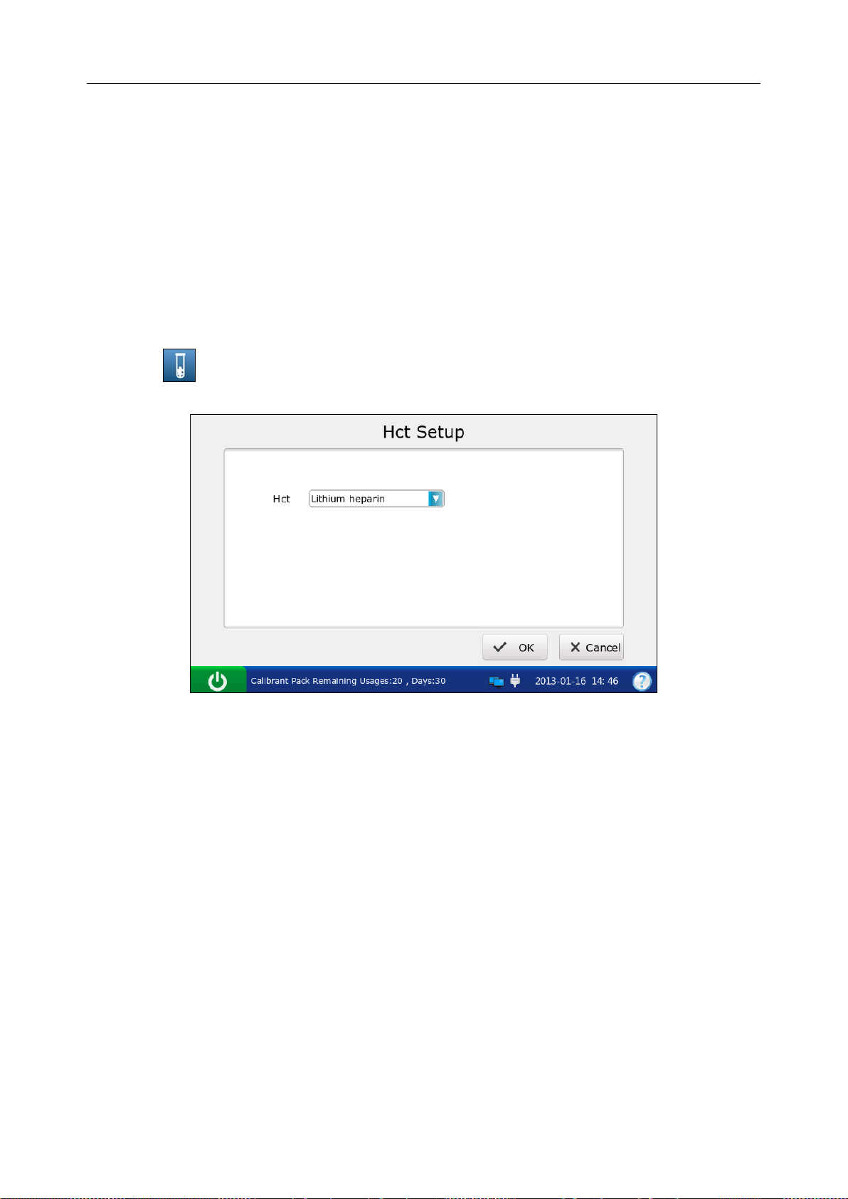
i15 Blood Gas and Chemistry Analysis System User Manual Setup
NOTE:
The default value is 1.0 for all slopes and 0.0 for all offsets.
Changing correlation factors affects future test results, but does not affect past,
stored test results.
4.3.6 Hct Setup
When only Hct levels are measur ed for whole blood samples, this menu allows you to sel ect the
anticoagulants.
1. Press to get access to the Hct Setup screen.
Figure 4-18 Hct Setup Screen
2. Select the desired anticoagulant. There ar e t hree o p ti on s: K2EDTA, K3EDTA, lithium heparin.
The default is lithium heparin.
3. Press OK to accept the changes, and the system will return to the Test Setup screen.
- 53 -
Page 62

i15 Blood Gas and Chemis t r y Analysis System User Manual Patient Analyzing
Chapter 5 Patient Analyzing
NOTE:
Take safety measures when working with biological samples, such as wearing
approved gloves, etc.
5.1 Sample Collection and Preparation
5.1.1 Sample Collection
Blood samples should be collected according to proper m edical guidelines containing collection
details, such as site selection, collection procedures, sampling devices, sample handling, etc.
Sterile techniques should be followed to prevent the site from being contaminated.
WARNING
Handle blood samples and collection devices with care, and wear approved protective
gloves to avoid direct contact with samples.
NOTE:
Only fresh whole blood samples are recommended for use.
When taken for electrolyte analysis, venous samples should not be collected f rom a
central venous catheter containing silver sulfadiazine or chlorhexidine, because they
have a great influence on sodium levels.
Samples should be collected by trained professionals.
For mixed venous samples, the system reports only pO2 result.
5.1.2 Anticoagulants
Only those sample devices containing the proper amount of calcium-titrated (balanced) heparin or
lithium heparin as the anticoagulant should be used to collect whole blood samples. If
calcium-titrated (balanced) heparin is used as an anticoagulant, the minimum heparin-to-blood
ratio should be 2.3 units of heparin per 1.0mL of blood sample. If a sample is analyzed for
ionized calcium, the maximum heparin-to-blood ratio should be 15 units of heparin per 1.0mL of
blood sample; if not, the maximum heparin-to-blood ratio should be 50 units of heparin per
1.0mL of blood sample.
CAUTION
If there are clots in the blood sample, discard it and collect samples again.
- 54 -
Page 63

i15 Blood Gas and Chemis t r y Analysis System User Manual Patient Analyzing
NOTE:
Don’t use the following anticoagulants: EDTA, citrate, and oxalate, because they have a
great influence on test results for pH and elec tr ol y t es.
5.1.3 Collection Devices and Volume
Samples can be introduced into the system with the following devices: syringes and capillary
tubes. It is recommended that VITREX® Blood Gas Capillary Tubes with a minimum volume,
filled of 175μL (Article Number: 182413) should be used.
NOTE:
The system uses 110μL samples for analysis, and make sure it can aspirate enough
sample.
The minimum fill volume for a 1mL syringe is 200μL.
The minimum fill v olum e for a 2mL syringe is 800μL.
The minimum fill volume for a 5mL syringe is 1.5mL.
Dislodge bubbles from the syringe, and cover it as soon as the sample is collected.
Cork should never be used to cover the syringe.
A capill ary tube should be filled to capacity and c overed securely. Cork or clay should
never be used to cover the capillary tube.
5.1.4 Notes
Follow the notes below to ensure that test results are accurate:
1. Cover the sample device immediately after collection to prevent it from being
contaminated by air.
2. Mix blood samples thoroughly prior to sample introduction.
3. Make sure there are no clots in blood samples, or else the results will be inaccurate.
4. Perform the sample test immediately after its collection to get the most accurate
results. Measure samples for blood gases and Ca++ within 10 minutes, and measure
samples for other analytes within 30 minutes.
5. Used sample devices are biohazardous waste, and should be handled abiding by
local regulatory guidelines.
- 55 -
Page 64

i15 Blood Gas and Chemis t r y Analysis System User Manual Patient Analyzing
5.2 Patient Analyzing
NOTE:
Ensure that th e displayed date and time are correct before each sample test, because
they are part of the patient sample data. Contact the administrator if the date and/or time
are incorrect.
5.2.1 Procedures for Patient Analyzing
1. Press the On/Off button on the left hand side of the analyzer to turn it on.
2. Enter the user name and password manually, and then press .
To enter the user name with the bar code scanner, press first, and then scan the user
name bar code.
Figure 5-1 Enter User Name a nd Password
3. Press the button for the blood sample t ype on the Main screen. √ will appear if the button is
selected. The default type is Arterial.
Figure 5-2 the Main Screen
- 56 -
Page 65

i15 Blood Gas and Chemis t r y Analysis System User Manual Patient Analyzing
CAUTION
Make sure that the selected sample type button is consistent with the blood sam ple, or
the result may be inaccurate.
4. Press Scan Barcode, and scan the bar code on a new cartridge foil pouch.
If the bar code is scanned successfully, the system will beep and the scanner will be
automatically turned off. If the scanned data is valid, the system will display th e screen for
the next procedure. If the scanned data is invalid, a message will pop up to prompt you.
5. Open the foil pouch and remove the cartridge from it.
NOTE:
Avoi d teari ng the bar code on t he foil pouc h .
For sample introduction with a capillary tube, insert a capillary adaptor into the fillport
after removing the cartridge.
6. Roll the syringe or capillary tube between pal ms and gently invert it end over end for several
times to mix the sample completely.
Figure 5-3 Mix Sample and I ns er t Cart r idge
NOTE:
To avoid inaccurate test results, mix the sample thoroughly prior to sample
introduction.
To avoid inaccurate test results, make sure there are no trapped bubbles or clots in
the sample.
- 57 -
Page 66

i15 Blood Gas and Chemis t r y Analysis System User Manual Patient Analyzing
7. Insert the syringe or capillary tube into the fillport of the cartridge.
NOTE:
When using a syringe, discard the first 2 dr ops of blood sample first, then re mov e the
needle from it, and finally insert it into the fillport.
When using a capillary tube, insert the capillary tube into the adaptor till the tube
reaches the interface between the adaptor and the cartridge.
8. Gently insert the cartridge into the cartridge port, and carefully press down to ensure it clicks
into place.
For a valid cartridge, the indicator in the cartridge port will turn green, and the system will
automatically aspirate calibrant. For an invalid cartridge, the indicator will turn red, the
cartridge will be ejected and a message will pop up to prompt you.
NOTE:
Never inject the sample. It will be aspirated automatically.
The cartridge can not be removed from the analyzer until the measurement is
complete.
9. Enter patient information. The screen displayed depends on the selection in section 4.3.2
Patient Information Setup. The screen for the default patient information setup is shown
below:
Figure 5-4 Enter Patient Data
- 58 -
Page 67

i15 Blood Gas and Chemis t r y Analysis System User Manual Patient Analyzing
NOTE:
It is not necessary to enter all the above parameters. You can press OK at any time.
If no parameters are selected in section 4.3.2 Patient Information Setup, the system
will go to the Aspirating Calibrant screen when the test cartridge is properly inserted.
The system can not go back to the screen for entering patient information after you
press OK, and patient information has to be edited in the patient sample database.
10. Press OK. The system will go to the following screens:
a). If the system is aspirating calibrant, the system will go to the following screen:
Figure 5-5 Aspirating Calibrant…
b). If the system is calibrating sensors, the system will go to the screen below:
Figure 5-6 Calibration in Progress
- 59 -
Page 68

i15 Blood Gas and Chemis t r y Analysis System User Manual Patient Analyzing
c). If the system is sampling, the system will go to the screen below:
Figure 5-7 Sampling…
d). If the system is analyzing patient samples, the system will go to the screen below:
Figure 5-8 Measurement i n Pr ogr ess
e). If the test is complete, the system will go to the screen below:
Figure 5-9 Sample Results
- 60 -
Page 69

i15 Blood Gas and Chemis t r y Analysis System User Manual Patient Analyzing
NOTE:
Upon the completion of the test, the indicator in the cartridge port will be off, the
message “Please Remove Cartridge” will be displayed on the status bar at the
bottom of the screen, and the cartridge will be ejected.
If the screen has not been touched for 10 seconds after the test is complete, the test
results will be displayed automatically even if you do not press OK.
If patient temp eratur e i s entere d, th e test resul ts will be displayed both at 37°C and at
the patient’s temperature.
If Auto Transmit is turned on in section 4.2.2 Network Setup, patient sample results
will be transmitted to the DMS automatically.
If Auto Print is selected in section 4.2.1 Printer Setup, patient sample results will be
printed automatically. If it is not selected, press Print to print the test results.
11. View the test results. The system displays the results for measured parameters by default.
Press Calculated to view the results for calculated parameters.
Figure 5-10 Calculated Parameters
Press Calibration to view the calibration results.
- 61 -
Page 70

i15 Blood Gas and Chemis t r y Analysis System User Manual Patient Analyzing
Figure 5-11 Calibration Parameters
Symbols such as > may appear on the Res ults screen , refer to section 5.2.2 Understanding Result
Symbols to understand their meanings.
WARNING
Never make treatment decisions according to test results containing symbols as
described in section 5.2.2 Understanding Result Symbols.
12. Remove the test cartridge from the system.
13. Press Home to return to the Main screen.
The contents of a patient sample report depend on the typ e of the test cartridge you have used, the
options selected in section 4.2.1 Printer Setup and section 4.3.2 Patient Information Setup, and
the errors and alarms the system detects during the measu rement. The table bel ow is an example
of a patient sample report:
EDAN i15
System ID 201303200023
Report Type Patient Sample Report
Sample Type Arterial
Print Time 2012-03-20 15:20:00
Test Time 2012-03-20 15:10:00
Patient ID 88888
Operator ID 55555
Patinet Information
- 62 -
Page 71

i15 Blood Gas and Chemis t r y Analysis System User Manual Patient Analyzing
Temperature 37 ℃
Sex Female
tHb 30 g/dL
FIO2 20
MCHC g/dL
RQ
Hb type Adult
Puncture site LR (Left Radial)
Bypass Pump Off
O2 mode
I/E Ratio 0/0
Vent mode None
......
Calibration Results
pH Fail
p
CO2 Pass
p
O2 Pass
Na+ Pass
K+ Pass
Ca++ Pass
Cl- Pass
Glu Pass
Lac Pass
Hct Pass
Cre Pass
BUN Pass
Results for Measured Parameters
pH ---
p
CO2 xxx mmHg
p
O2 70 mmHg
Na+ ??? mmol/L
K+ 1.0 ↓ mmol/L
Ca++ 200 ↑ mmol/L
Cl- > mmol/L
Glu < mmol/L
Lac 5 *** mmol/L
…
Results for Calculated Parameters
cH+ 1 nmol/L
pH(T) 1
- 63 -
Page 72

i15 Blood Gas and Chemis t r y Analysis System User Manual Patient Analyzing
p
CO2(T) 1 ***
p
O2(T) 1 >
-
HCO
act 1 <
3
-
HCO
std 1
3
BE(ecf) 1
Ca++(7.4) 1
…
Reference Ranges
pH [7.35 - 7.45]
p
CO2 [35.0 - 45.0] mmHg
p
O2 [80.0 - 100.0] mmHg
Na+ [138.0 - 146.0] mmol/L
K+ [3.50 - 4.90] mmol/L
Ca++ [1.12 - 1.32] mmol/L
Cl- [98 - 109] mmol/L
Glu [3.9 - 5.8] mmol/L
Lac [0.36 - 1.7] mmol/L
Hct [35 – 51] %
Cre [0.6 - 1.3] mg/dL
BUN
5.2.2 Understanding Result Symbols
The following table shows the symbols that may appear on the screen:
Symbol Description
> or < The result is above or below the measurement range.
↑ or ↓ The result is above or below the reference range.
--- The measured parameter fails calibration.
The measured param eter fail s qualit y control (QC) tests, and QC lockout f unction is
xxx
***
??? The result for the measured parameter is invalid.
NOTE:
Invalid test resul t for a cal c ulat e d p ar a met er will not be displayed on the screen.
enabled in Setup.
The measured param eter fail s qualit y control (QC) t ests, and QC lockout function is
disabled in Setup.
The result for the calculated p arameter is v alid, but the m easured par ameter use d to
determine this calculated parameter fails quality control (QC) tests, and QC lockout
function is disabled in Setup.
Valid test result for a calculated parameter will not be displayed on the screen, if the
measured param eter used to determine the result fails quality control (QC) tests, and
QC lockout function is enabled in Setup.
- 64 -
Page 73
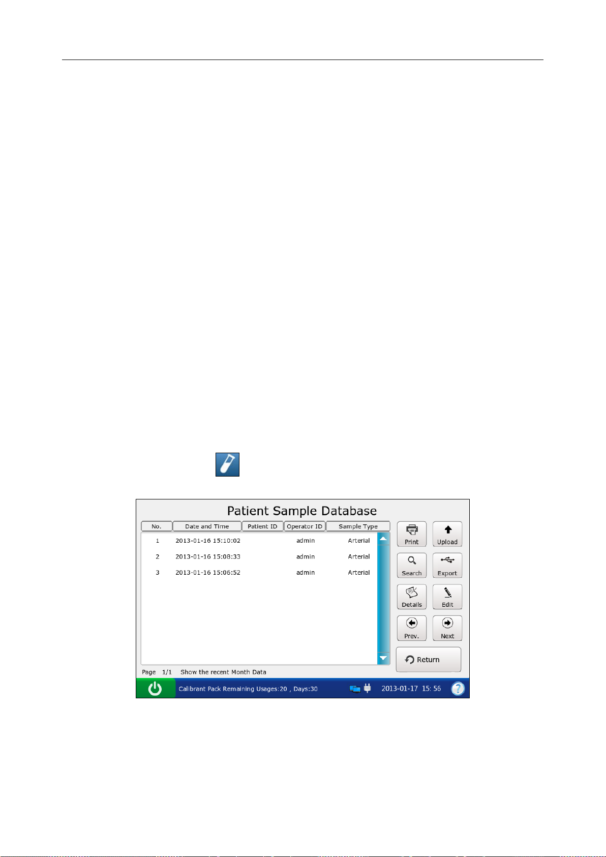
i15 Blood Gas and Chemis t r y Analysis System User Manual Patient Analyzing
5.3 Patient Sample Database
The patient sample database displays patient sample data for the most recent month by default,
and it can store up to 10000 data entries. The system displays 50 pieces of data on every page.
Press Prev. and Next to page through the screens of the displayed data entries. When 80% o f the
space is occupied, the system will prompt you to export the stored data to a removable disk (such
as a USB drive). If data is not exported, the system will continue to save new data. When the
database is full, the system will always prompt you to export data. If data is still not exported, the
system will automatically delete the oldest one to accommodate a new one. The following
operations can be p erformed in the patient sample database: trans mitting patient sample data to
the Data Management System (DMS) through WIFI or the network, exporting patient sample
data to a removable disk (such as a USB drive), viewing the details of patient sample data, editing
patient information, searching for and printing patient sample data, etc.
NOTE:
Only patient information data can be edited.
Test results for calculat ed para meters may be changed due to the alter ation of p atient
information data.
On the Database screen, press to access the Patient Sample Database screen.
Figure 5-12 Patient Sample Database Screen
- 65 -
Page 74
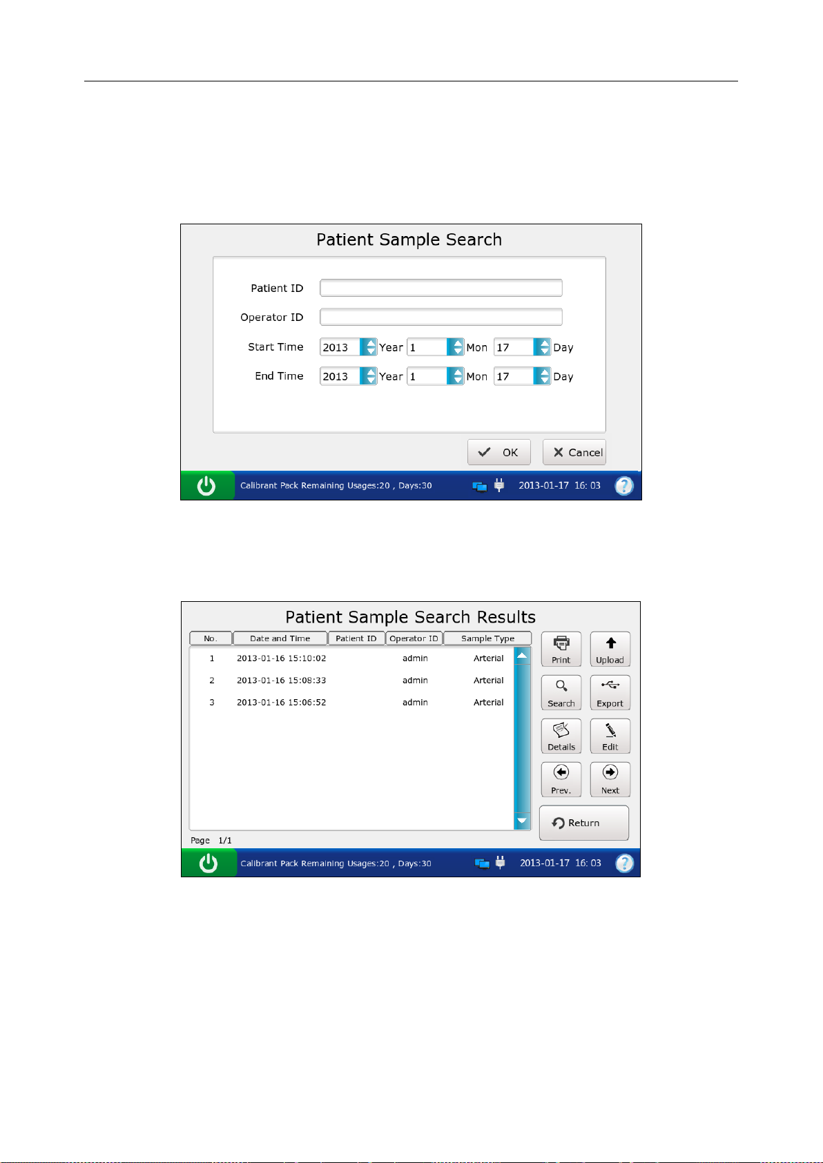
i15 Blood Gas and Chemis t r y Analysis System User Manual Patient Analyzing
5.3.1 Searching for Patient Sample Data
1. On the Patient Sample Database screen, press Search.
2. Enter the search conditions, and press OK.
Figure 5-13 Enter Search Condition s
3. The system automatically begins the search and displays the results.
Figure 5-14 Search Results
4. Press Return to go back to the Patient Sample Database screen.
- 66 -
Page 75
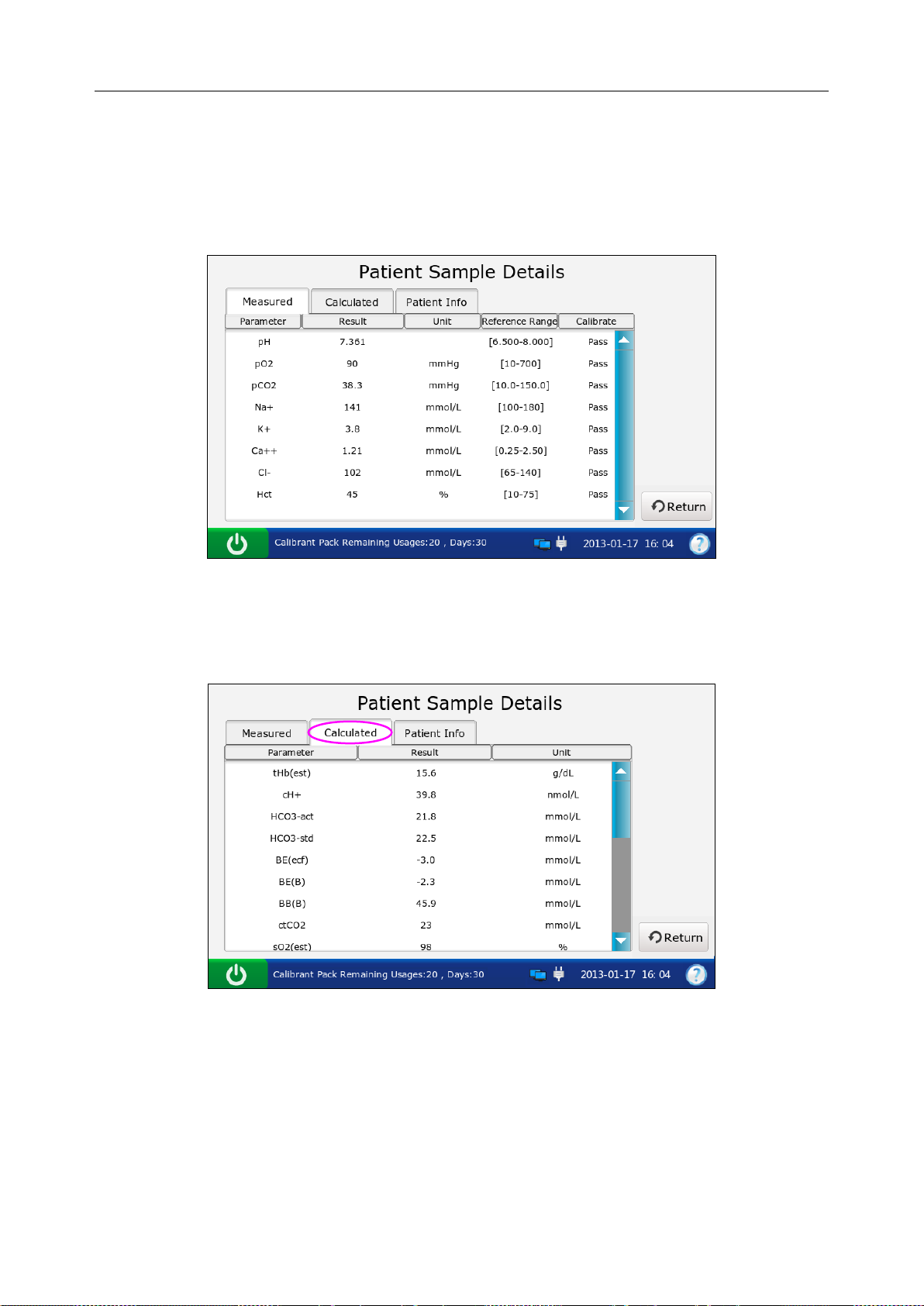
i15 Blood Gas and Chemis t r y Analysis System User Manual Patient Analyzing
5.3.2 Viewing Details of Patient Sample Data
1. Press the patient sample data you want to view.
2. Press Details. The system displays the details of measured parameters by default .
Figure 5-15 Details of Measured Paramet ers
3. Press Calculated to view the details of calculated param ete rs .
Figure 5-16 Details of Calculat ed Parameters
4. Press Patient Info to view the details of patient information.
- 67 -
Page 76
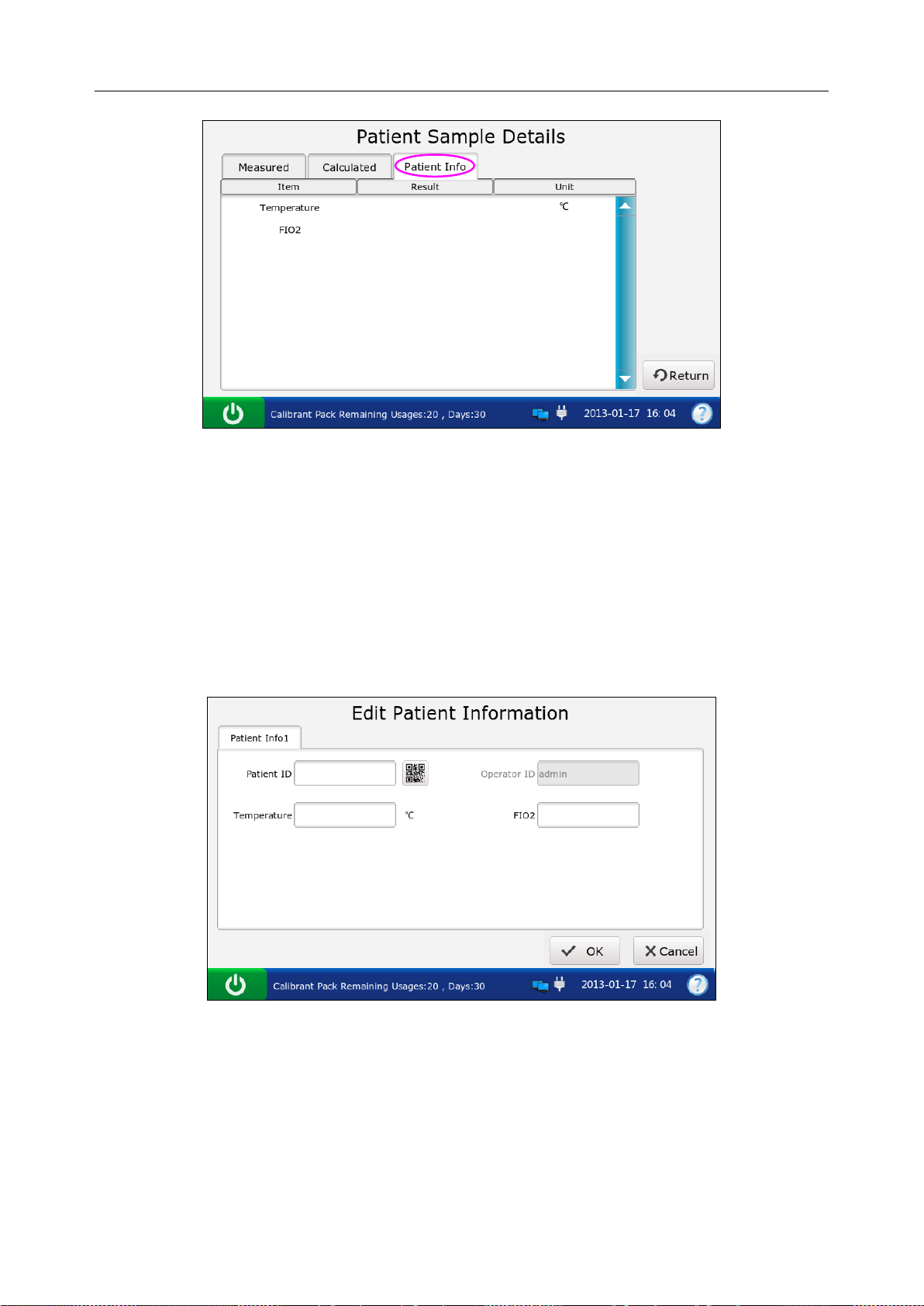
i15 Blood Gas and Chemis t r y Analysis System User Manual Patient Analyzing
Figure 5-17 Details of Pat i ent I nformation
5. Press Return to go back to the Patient Sample Database screen.
5.3.3 Editing Patient Information Data
1. Select the desired patient sample data, and then press Edit.
2. Edit the patient information data. The following screen will be displayed for the default
patient information setup:
Figure 5-18 Edit Patient Data
NOTE:
The screen displayed depends on the selection in section 4.3.2 Patient Information
Setup.
3. Press OK to save the changes, and the system will return to the Patient Sample Database
screen.
- 68 -
Page 77

i15 Blood Gas and Chemis t r y Analysis System User Manual Patient Analyzing
5.3.4 Exporting/Uploading/Printing Patient Sample Data
1. Open the patient sample database.
2. Select the desired patient sample data.
To Do this
Export
Upload
Print
Insert a removable disk into the analyzer, and then press Export.
Press Upload.
Press Print.
NOTE:
If no patient s am pl e data is selec t ed b efore pressing Export/Upload/Print, all o f the d ata
stored in the patient sample database will be exported/uploaded/printed.
- 69 -
Page 78
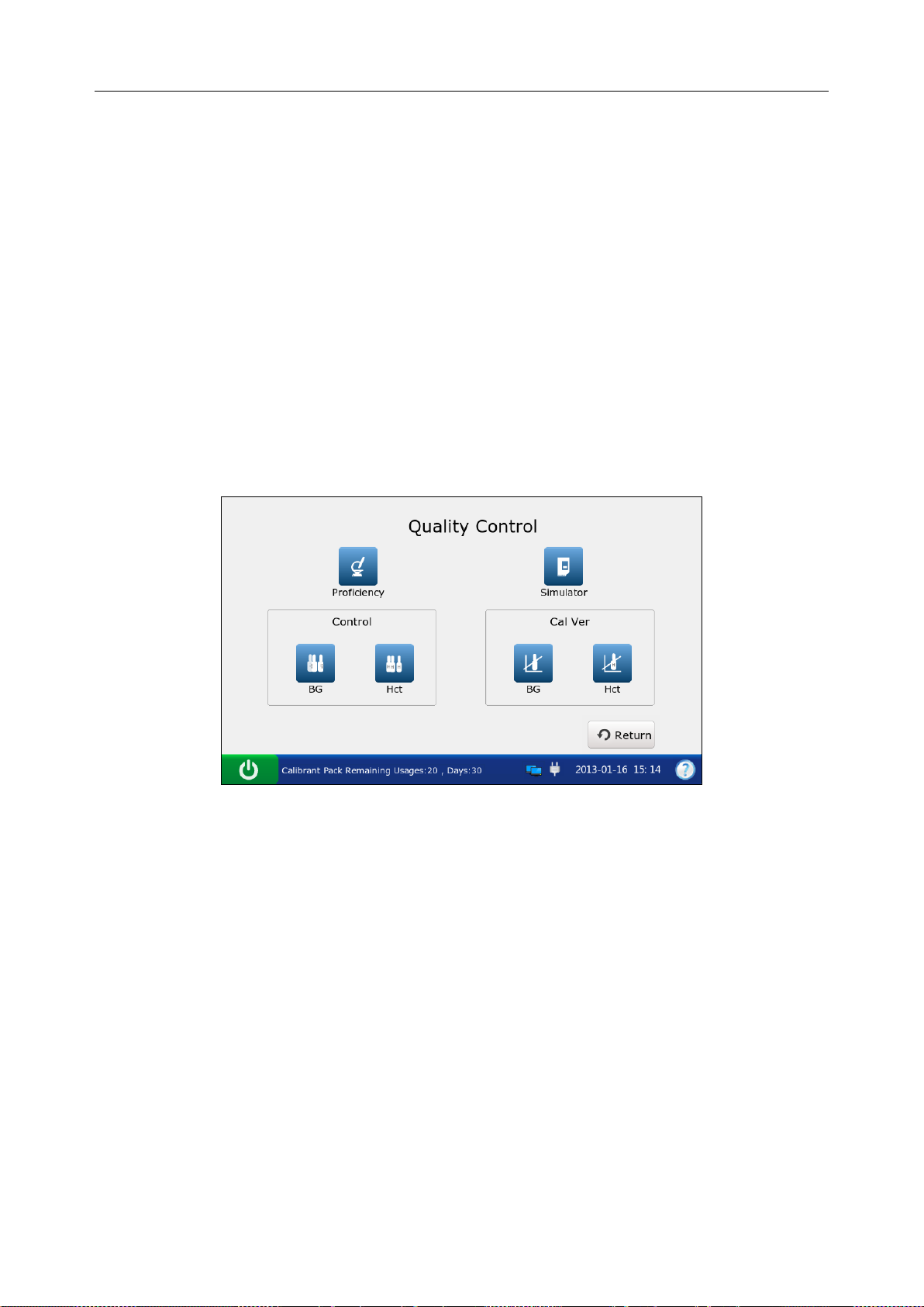
i15 Blood Gas and Chemistry Analysis System User Manual Quality Control (QC) Te s ts
Chapter 6 Quality Control (QC) Tests
Quality Control (QC) tests could ensure the normal operation of the system and the reliability of
test results. Policies related to the measurement of QC samples are at the discretion of your
individual institution. It is recommended to perform QC tests in the following situations:
You are using the system for the first time.
You wish to verify the performance of newly received test cartridges.
You wish to verify the storage condition of test cartridges.
You wish to verify the performance of the system.
You doubt test results.
Figure 6-1 Quality Control Screen
6.1 Control Test
Control tests are intended to verify the efficient performance of the system. To verify the
performance of each lot of newly received test cartridges, analyze at least two levels of controls
in duplicate using a verified analyzer.
6.1.1 Controls
Controls are intended for use to monitor test cartridge performance at multiple points within the
clinical range. Controls used are RNA Medical® QC823 Blood
Gas●Electrolyte●Metabolite●BUN controls and RNA Medical® QC900 Hematocrit controls. The
concentrations of reactive ingredients in various levels of controls are known. Controls do not
contain human serum or serum products, but do contain buffers and preservatives. Acceptable
- 70 -
Page 79

i15 Blood Gas and Chemistry Analysis System User Manual Quality Control (QC) Te s ts
ranges for controls specific to the i15 Blood Gas and Chemistry Analysis System are
programmed in the bar code on the user manual for controls provided by EDAN.
Packaging
1. RNA Medical® QC823 Blood Gas●Electrolyte●Metabolite●BUN controls are contained in
2.5mL glass ampoules, and RNA Medical® QC900 Hematocrit controls are contained in
1.7mL glass ampoules.
2. The controls package contains information such as the control name, level, lot number and
expiration date, etc.
Storage and Usage
Controls should be stored at 2 - 8°C (avoid free zing) with the relative humidity of 25% - 93%
(non-condensing).
Controls should be used at 10 - 31°C with the relative humidity of 25% - 80% (non-condensing).
Before Use
Controls should be equilibrated to room temperature before use. If oxygen is to be measured, the
ampoule needs to stand at room temperature for 4 hours. If not, the amp oule needs to stand at
room temperature for only about 30 minutes.
Immediately before use, mix controls completely by shaking the ampoule gently, and always hold
an ampoule at tip and at bottom with forefinger and thumb to minimize increasing controls
temperature. Tap the tip of the ampoule carefully with your fingernail to remove any solution.
NOTE:
Store and use controls according to the user manual, and use them before the
expiration date as labeled on the package.
Only controls provided by EDAN or its authorized distributors should be used.
For test cartridges with pH, pCO2, pO2, Ca++ sensors, a new ampoule and syringe or
capillary tube s hould b e used for each t est. For test cart r idges without pH, pCO2, pO2,
Ca++ sensors, the r em ai ning solution can still be use d if the ampoule is opened wi thi n
10 minutes.
The test results should fall within the acceptable ranges programmed in the bar code
on the user manual for controls provided by EDAN.
- 71 -
Page 80

i15 Blood Gas and Chemistry Analysis System User Manual Quality Control (QC) Te s ts
6.1.2 Procedures for Control Test
Follow the steps below to perform a control test:
1. Examine the package label of controls to ensure they have not expired.
2. Remove an ampoule from the box of controls and equilibrate it to room temperature.
If oxygen is to be measured, the ampoule needs to stand at room temperature fo r 4 hours. If
not, the ampoule needs to stand at room temperature for only about 30 minutes.
3. Press the On/Off button on the left hand side of the analyzer to turn it on.
4. Enter the user name and password manually, and then press .
To enter the user name with the bar code scanner, press first, and then scan the user
name bar code.
Figure 6-2 Enter User Name and Password
5. On the Main screen, press to go to the Quality Control screen.
6. Select the desired control type.
Press to perform a control test for blood gases and electrolytes.
Press to perform a control test for Hct.
- 72 -
Page 81

i15 Blood Gas and Chemistry Analysis System User Manual Quality Control (QC) Te s ts
7. Press Scan Barcode, and scan the bar code on a new cartridge foil pouch.
If the bar code is scanned successfully, the system will beep and the scanner will be
automatically turned off. If the scanned data is valid, the system will display the screen for
the next procedure. If the scanned data is invalid, a message will pop up to prompt you.
Figure 6-3 Scan Bar Code
8. Open the foil pouch and remove the cartridge from it.
NOTE:
Avoi d teari ng the bar code on t he foil pouc h .
For sample introduction with a capillary tube or an ampoule, insert a capillary
adaptor/ampoule adaptor into the fillport after removing the cartridge.
When inserting an ampoule adaptor into the fillport of a test cartridge, make sure the
indent of the adaptor is on the upside as shown in the picture below:
- 73 -
Page 82

i15 Blood Gas and Chemistry Analysis System User Manual Quality Control (QC) Te s ts
9. Press Scan Barcode, and scan the bar code on the controls user manual.
If the bar code is scanned successfully, the system will beep and the scanner will be
automatically turned off. If the scanned data is valid, the system will display the screen for
the next procedure. If the scanned data is invalid, a message will pop up to prompt you.
Figure 6-4 Scan Bar Code
NOTE:
Keep the controls user manual for a future control test use.
10. Mix the controls completely by shaking the ampoule gently, and then tap the tip of the
ampoule carefully with your fingernail to remove any solution.
Figure 6-5 Mix Controls and Insert Cartridge
NOTE:
Avoid heating the ampoule with your hands when shaking the ampoule.
- 74 -
Page 83

i15 Blood Gas and Chemistry Analysis System User Manual Quality Control (QC) Te s ts
11. Open the ampoule by snapping off the top and immediately transfer control solution by
slowly drawing an appropriate amount of solution with a syri nge or c apillary tube from the
bottom of the ampoule.
NOTE:
When using an ampoule for sample introduction, you need not transfer control
solution. Insert the ampoule into the adaptor after opening it, and directly go to step
13.
Take protective measures when opening the ampoule, such as using gloves, tissue,
etc.
12. Insert the syringe or capillary tube into the fillport of the cartridge.
NOTE:
When using a syringe, discard the first 2 drops of solution first, then remove the
needle from it, and finally insert it into the fillport.
When using a cap illary tube, directly insert the capillary tube into the adaptor till the
tube reaches the interface between the adaptor and the cartridge.
To avoid inaccurate test results, make sure there are no bubbles in the sample. If
bubbles continually exist, use a new ampoule and syringe or capillary tube to collect
samples again.
13. Gently insert the cartridge into the cartridge port, and carefully press down to ensure that it
clicks into place.
For a valid cartridge, the indicator in the cartridge port will turn green, and the system will
automatically aspirate calibrant. For an invalid cartridge, the indicator will turn red, the
cartridge will be ejected and a message will pop up to prompt you.
NOTE:
The cartridge can not be removed from the analyzer until the measurement is
complete.
Never inject the sample. It will be aspirated automatically.
- 75 -
Page 84

i15 Blood Gas and Chemistry Analysis System User Manual Quality Control (QC) Te s ts
14. The system automatically aspirates calibrant.
Figure 6-6 Aspirating Calibrant…
15. The system automatically performs calibration.
Figure 6-7 Calibration in Progress
16. The system automatically aspirates samples when calibration is complete.
Figure 6-8 Sampling…
- 76 -
Page 85

i15 Blood Gas and Chemistry Analysis System User Manual Quality Control (QC) Te s ts
17. The system automatically analyzes the sample upon the completion of sampling.
Figure 6-9 Measurement i n Pr ogr ess
18. The system automatically displays the test results upon the completion of the test.
Figure 6-10 Control Test Results
19. View the results.
NOTE:
The system will indicate whether the results are within or outside the acceptable
ranges with Under Control/Out of Control.
If a parameter fails calibration, the system will not be able to determine whether it is
under control, and will display Calibration Failure to prompt you.
- 77 -
Page 86

i15 Blood Gas and Chemistry Analysis System User Manual Quality Control (QC) Te s ts
The system will not report the result for a parameter failing the control test in the
patient sample analysis, if QC Lockout function is enabled in Setup. To report the
result for the paramet e r, repeat the control test till the parameter passes it.
If the results are outside the acceptabl e ranges, check the following items first, and
then perform another test.
Refer to the user manual to confirm that the test procedures are correct.
Test cartridges and controls are stored properly and have not expired.
The system passes the electronic simulator test.
If all the above items are verified, but the results are still outside the acceptable
ranges, please stop using the system and contact EDAN or i t s a uth or i zed distributors
for assistance.
20. Remove the test cartridge from the system.
21. Press Print to print the results.
22. Press Home to return to the Main screen.
The contents of a control test report depend on the t ype of controls you have used, the type of the
test cartridge you have used,the options selected in section 4.2.1 Printer Setup and the errors and
alarms the system detects during the analysis. Here is an example of a control test report.
Control Test Report
EDAN i15
System ID 201303200023
Report Type Control Test Report
Print Time 2012-03-20 15:20:00
Test Time 2012-03-20 15:00:00
Operator ID 55555
Lot Number 21209
Calibration Results
pH Pass
p
CO2 Fail
p
O2 Pass
…
- 78 -
Page 87

i15 Blood Gas and Chemistry Analysis System User Manual Quality Control (QC) Te s ts
Control Test Results
pH 7.5
p
CO2 --- mmHg
p
O2 70 mmHg
Na+
K+
Ca++
ClGlu
Lac
Hct
Cre
BUN
pH Under Control
p
CO2 Calibration Failure
p
O2 Under Control
Na+ Under Control
K+ Under Control
Ca++ Under Control
Cl- Under Control
Glu Under Control
Lac Under Control
Hct Under Control
Cre Under Control
BUN Under Control
Control Ranges
pH [7.35 - 7.45]
p
CO2 [35.0 - 45.0] mmHg
p
O2 [80.0 - 100.0] mmHg
Na+ [138.0 - 146.0] mmol/L
K+ [3.50 - 4.90] mmol/L
Ca++ [1.12 - 1.32] mmol/L
Cl- [98 – 109] mmol/L
Glu [3.9 - 5.8] mmol/L
Lac [0.36 - 1.7] mmol/L
Hct [35 – 51] %
Cre [0.6 - 1.3] mg/dL
BUN
- 79 -
Page 88

i15 Blood Gas and Chemistry Analysis System User Manual Quality Control (QC) Te s ts
6.1.3 Control Database
The control databas e displays control test data for the most recent month b y default, and it can
hold up to 1000 data entries. The system displays 50 data entries on every page. Press Prev. and
Next to page through the screens of the displayed data entries. When 80% of the space is
occupied, the s ystem will prompt you to export the stored data to a removable disk (such as a
USB drive). If data is not exported, the system will continue to save new data. When the dat abase
is full, the system will always prompt you to export the stored data. If data is st ill not exported,
the system will automatically delete the oldest one to accommodate a new one. The following
operations can be performed in the control database: transmitting control test data to the Data
Management System (DMS) through WIFI or the network, exporting control test data to a
removable disk (such as a USB dri ve), viewing t he details of control test data, searching for and
printing control test data, etc.
On the Database screen, press to get to the Control Database screen.
Figure 6-11 Control Database Screen
6.1.3.1 Searching for Control Test Data
1. On the Control Database screen, press Search.
2. Enter the search conditions, and press OK.
- 80 -
Page 89

i15 Blood Gas and Chemistry Analysis System User Manual Quality Control (QC) Te s ts
Figure 6-12 Enter Search Condition s
3. The system automatically begins the search and displays the results.
Figure 6-13 Search Results
4. Press Return to go back to the Control Database screen.
6.1.3.2 Viewing Details of Control Test Data
1. Press the control test data you want to view.
2. Press Details. The system displays the details:
- 81 -
Page 90
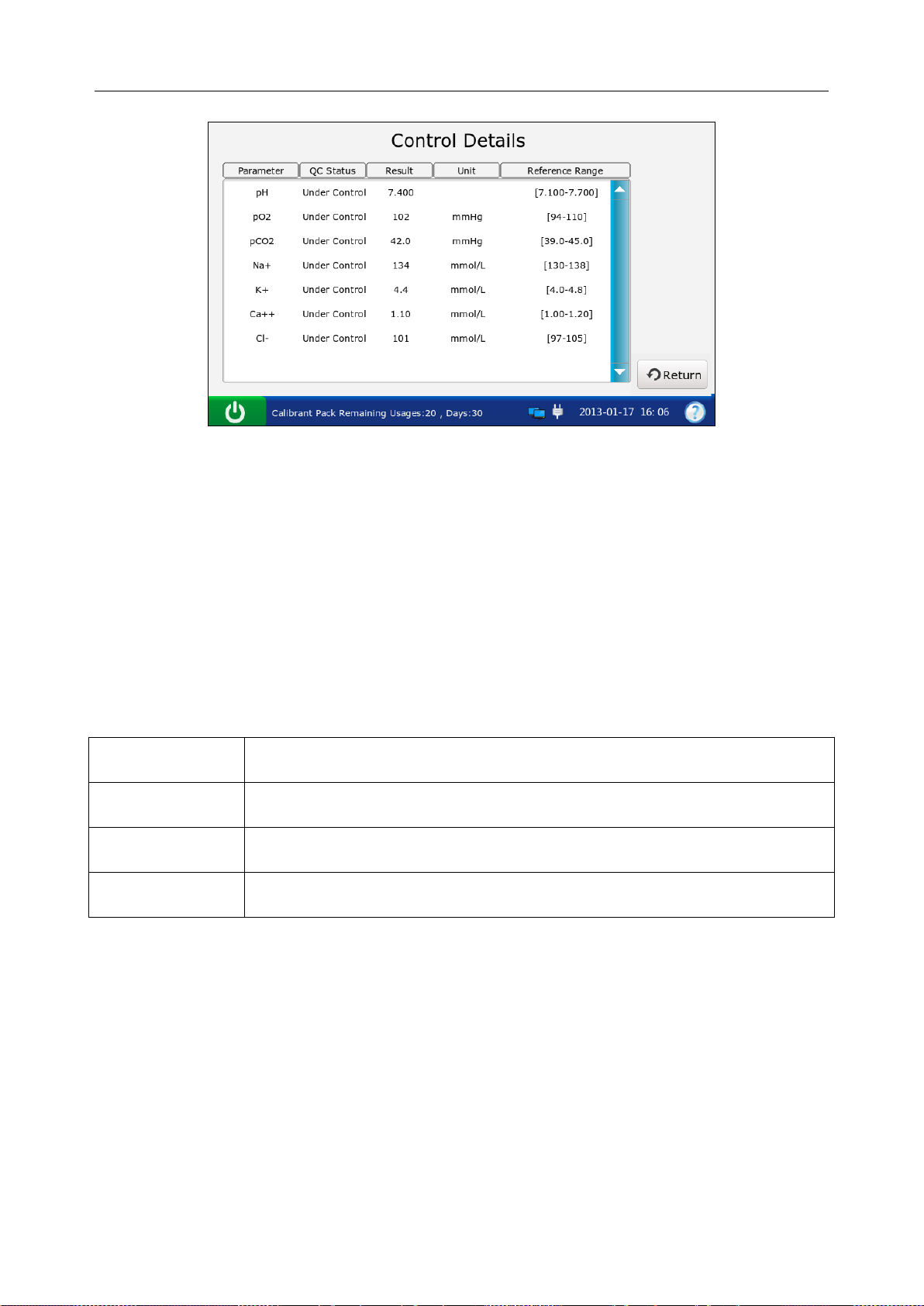
i15 Blood Gas and Chemistry Analysis System User Manual Quality Control (QC) Te s ts
Figure 6-14 Details of Control Test Results
3. View the details.
4. Press Return to go back to the Control Database screen.
6.1.3.3 Exporting/Uploading/Printing Control Test Data
1. Open the control database.
2. Select the desired control test data.
To Do this
Export
Upload
Print
Insert a removable disk into the analyzer, and then press Export.
Press Upload.
Press Print.
NOTE:
If no control test data is selected before pressing Export/Upload/Print, all of the data
stored in the control database will be exported/uploaded/printed.
- 82 -
Page 91

i15 Blood Gas and Chemistry Analysis System User Manual Quality Control (QC) Te s ts
6.2 Proficiency Test
Proficiency tests ar e also called external quality control tests. In prof iciency tests, the anal ysis of
unknown samples from external quality control providers can reflect the accuracy of the system.
6.2.1 Procedures for Proficiency Test
Follow the directions below to perform a proficiency test:
1. Examine the package label of proficiency samples to ensure they have not expired.
2. Remove an ampoule from the box and equilibrate it to room temperature.
If oxygen is to be measured, the ampoule needs to stand at room temperature for 4 hours. If
not, the ampoule needs to stand at room temperature for only about 30 minutes.
3. Press the On/Off button on the left hand side of the analyzer to turn it on.
4. Enter the user name and password manually, and then press .
To enter the user name with the bar code scanner, press first, and then scan the user
name bar code.
Figure 6-15 Enter User Nam e and Password
5. On the Main screen, press to go to the Quality Control screen, and then press .
- 83 -
Page 92

i15 Blood Gas and Chemistry Analysis System User Manual Quality Control (QC) Te s ts
6. Press Scan Barcode, and scan the bar code on a new cartridge foil pouch.
If the bar code is scanned successfully, the system will beep and the scanner will be
automatically turned off. If the scanned data is valid, the system will display the screen for
the next procedure. If the scanned data is invalid, a message will pop up to prompt you.
Figure 6-16 Scan Bar Code
7. Open the foil pouch and remove the cartridge from it.
NOTE:
Avoi d teari ng the bar code on t he foil pouc h .
For sample introduction with a capillary tube or an ampoule, please insert a capillary
adaptor/ampoule adaptor into the fillport after removing the cartridge.
When inserting an ampoule adaptor into the fillp ort of a test cartridge, make sure the
indent of the adaptor is on the upside as shown in the picture below:
- 84 -
Page 93
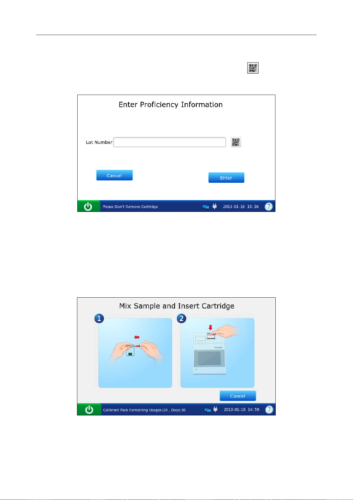
i15 Blood Gas and Chemistry Analysis System User Manual Quality Control (QC) Te s ts
8. Enter the lot number of the proficiency sample, and then press Enter.
To enter the lot number information with the bar code scanner, press first, and then scan
the bar code.
Figure 6-17 Enter Information
NOTE:
Only lot number information within 1-16 digits is acceptable.
9. Mix the proficiency sample completely by shaking the ampoule gently, and then tap the tip of
the ampoule carefully with your fingernail to remove any solution.
Figure 6-18 Mix Proficiency Sample and Insert Cartridge
NOTE:
Avoid heating the ampoule with your hands when shaking the ampoule.
- 85 -
Page 94

i15 Blood Gas and Chemistry Analysis System User Manual Quality Control (QC) Te s ts
10. Open the ampoule by snapping off the top and immediately transfer proficiency solution by
slowly drawing an appropriate amount of solution with a syringe or capillary tube from the
bottom of the ampoule.
NOTE:
When using an ampoule, you need not transfer the proficiency solution. Insert the
ampoule into the adaptor after opening it, and directly go to step 12.
Take protective measures when opening the ampoule, such as using gloves, tissue,
etc.
11. Insert the syringe or capillary tube into the fillport of the cartridge.
NOTE:
When using a syringe, discard the first 2 drops of solution first, then remove the
needle from it, and finally insert it into the fillport.
When using a capilla ry tube, directly insert the capillary tube into the adaptor till the
tube reaches the interface between the adaptor and the cartridge.
To avoid inaccurate test results, make sure there are no bubbles in the sample. If
bubbles continually exist, use a new ampoule and syringe or capillary tube to collect
samples again.
12. Gently insert the cartridge into the cartridge port, and carefully press down to ensure that it
clicks into place.
For a valid cartridge, the indicator in the cartridge port will turn green, and the system will
automatically aspirate calibrant. For an invalid cartridge, the indicator will turn red, the
cartridge will be ejected and a message will pop up to prompt you.
NOTE:
The cartridge can not be removed from the analyzer until the measurement is
complete.
Never inject the sample. It will be aspirated automatically.
- 86 -
Page 95
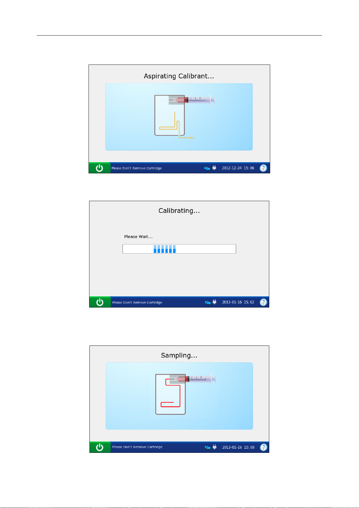
i15 Blood Gas and Chemistry Analysis System User Manual Quality Control (QC) Te s ts
13. The system automatically aspirates calibrant.
Figure 6-19 Aspirating Calibrant…
14. The system automatically performs calibration.
Figure 6-20 Calibration in Progress
15. The system automatically aspirates samples when calibration is complete.
Figure 6-21 Sampling…
- 87 -
Page 96

i15 Blood Gas and Chemistry Analysis System User Manual Quality Control (QC) Te s ts
16. The system automatically analyzes the sample upon the completion of sampling.
Figure 6-22 Measureme nt in Progress
17. The system automatically displays the test results upon the completion of the test.
Figure 6-23 Proficiency Test Results
18. View the results.
19. Remove the test cartridge from the system.
20. Press Print to print the results.
21. Press Home to return to the Main screen.
- 88 -
Page 97

i15 Blood Gas and Chemistry Analysis System User Manual Quality Control (QC) Te s ts
Here is an example of a proficiency test report.
Proficiency T est Report
EDAN i15
System ID 201303200023
Report Type Proficiency Test Report
Print Time 2012-03-20 15:20:00
Test Time 2012-03-20 15:10:00
Operator ID 55555
Lot Number 21209
Calibration Results
pH Pass
p
CO2 Pass
p
O2 Pass
…
Proficiency Test Results
pH 7.4
p
CO2 40 mmHg
p
O2 90 mmHg
Na+ 140 mmol/L
K+ 4.0 mmol/L
Ca++ 1.2 mmol/L
Cl- 101 mmol/L
Glu 4.1 mmol/L
Lac 0.8 mmol/L
Hct 40 %
Cre 0.7 mg/dL
BUN 23 mmol/L
6.2.2 Proficiency Database
The proficiency database d isplays all the proficiency test data b y default, and it can store up to
1000 data entries. The system displays 50 data entries on every page. Press Prev. and Next to
page through the screens of the displayed data entries. The following operations can be
performed in the proficiency database: transmitting proficiency test data to the Data Man a gement
System (DMS) through WIFI or the network, exporting profici ency test data to a removable disk
(such as a USB drive), viewing the details of proficiency test data, searching for and printing
proficiency test data, etc.
- 89 -
Page 98

i15 Blood Gas and Chemistry Analysis System User Manual Quality Control (QC) Te s ts
On the Database screen, press to get access to the Proficiency Database screen.
Figure 6-24 Proficiency D at abase Screen
6.2.2.1 Searching for Proficiency Test Data
1. On the Proficiency Database screen, press Search.
2. Enter the search conditions, and press OK.
Figure 6-25 Enter Search Condition s
3. The system automatically begins the search and displays the results.
- 90 -
Page 99

i15 Blood Gas and Chemistry Analysis System User Manual Quality Control (QC) Te s ts
Figure 6-26 Search Results
4. Press Return to go back to the Proficiency Database screen.
6.2.2.2 Viewing Details of Proficiency Test Dat a
1. Press the proficiency test data you want to view.
2. Press Details. The system displays the details:
Figure 6-27 Details of Proficiency Test Results
3. View the details.
4. Press Return to go back to the Proficiency Database screen.
- 91 -
Page 100

i15 Blood Gas and Chemistry Analysis System User Manual Quality Control (QC) Te s ts
6.2.2.3 Exporting/Uploading/Printing Proficiency T est Data
1. Open the proficiency database.
2. Select the desired proficiency test data.
To Do this
Export
Upload
Print
NOTE:
If no proficiency test data is sel ect ed be fore pr ess ing Export/Upload/Print, all of the data
stored in the proficiency database will be exported/uploaded/printed.
Insert a removable disk into the analyzer, and then press Export.
Press Upload.
Press Print.
6.3 Simulator Test
6.3.1 Procedures for External Simulator Test
Follow the procedures below to perform an external simulator test:
1. Press the On/Off button on the left hand side of the analyzer to turn it on.
2. Enter the user name and password manually, and then press .
To scan the bar code of the user name, press first, and then scan the bar code.
Figure 6-28 Enter User Nam e and Password
- 92 -
 Loading...