

Page 1

Page 2

About this Manual
P/N: 01.54.455327
MPN: 01.54.455327017
Release Date: Jan. 2015
© Copyright EDAN INSTRUMENTS, INC. 2008 - 2015. All rights reserved.
Statement
This manual will help you understand the operation and maintenance of the product better. It is
reminded that the product shall be used strictly complying with this manual. User’s operation
failing to comply with this manual may result in malfunction or accident for which EDAN
INSTRUMENTS, INC. (hereinafter called EDAN) can not be held liable.
EDAN owns the copyrights of this manual. Without prior written consent of EDAN, any
materials contained in this manual shall not be photocopied, reproduced or translated into other
languages.
Materials protected by the copyright law, including but not limited to confidential information
such as technical information and patent information are contained in this manual, the user shall
not disclose such information to any irrelevant third party.
The user shall understand that nothing in this manual grants him, expressly or implicitly, any
right or license to use any of the intellectual properties of EDAN.
EDAN holds the rights to modify, update, and ultimately explain this manual.
Product Information
Product Name: Fetal & Maternal Monitor
Model: F6, F6 Express, F9, F9 Express
Responsibility of the Manufacturer
EDAN only considers itself responsible for any effect on safety, reliability and performance of
the equipment if:
Assembly operations, extensions, re-adjustments, modifications or repairs are carried out by
persons authorized by EDAN, and
The electrical installation of the relevant room complies with national standards, and
The instrument is used in accordance with the instructions for use.
Upon request, EDAN may provide, with compensation, necessary circuit diagrams, and other
I
Page 3

information to help qualified technician to maintain and repair some parts, which EDAN may
define as user serviceable.
Terms Used in this Manual
This guide is designed to give key concepts on safety precautions.
WARNING
A WARNING label advises against certain actions or situations that could result in personal
injury or death.
CAUTION
A CAUTION label advises against actions or situations that could damage equipment, produce
inaccurate data, or invalidate a procedure.
NOTE
A NOTE provides useful information regarding a function or a procedure.
II
Page 4

Table of Contents
Chapter 1 Safety Guide ················································································································ 1
1.1 Intended Use....................................................................................................................... 1
1.2 Features .............................................................................................................................. 2
1.3 Instruction for Safe Operation ............................................................................................ 2
1.4 Ultrasound Safety Guide .................................................................................................... 3
1.5 Safety Precautions .............................................................................................................. 4
1.6 Definitions and Symbols .................................................................................................. 11
Chapter 2 Installation Guide ······································································································ 15
2.1 Opening and Checking Package ....................................................................................... 15
2.2 Installing Battery .............................................................................................................. 15
2.3 Installing Monitor ............................................................................................................ 16
2.4 Connecting Power Cable .................................................................................................. 17
Chapter 3 Monitor and Accessories ··························································································· 18
3.1 Overview .......................................................................................................................... 18
3.1.1 Keys and Control Knob .......................................................................................... 19
3.1.2 Indicators ................................................................................................................ 21
3.2 Accessories ....................................................................................................................... 22
3.2.1 Ultrasound (US) Transducers ................................................................................. 22
3.2.2 TOCO Transducers ................................................................................................ 22
3.2.3 Belt ......................................................................................................................... 23
3.2.4 Remote Event Marker ............................................................................................ 23
3.2.5 DECG Cable........................................................................................................... 23
3.2.6 Fetal Spiral Electrode ............................................................................................. 24
3.2.7 IUP Cable ............................................................................................................... 24
3.2.8 IUP Catheter ........................................................................................................... 25
3.2.9 ECG Cable ............................................................................................................. 25
3.2.10 SpO2 Sensor ......................................................................................................... 25
3.2.11 NIBP Cuff ............................................................................................................ 26
3.2.12 TEMP Sensor ....................................................................................................... 26
3.3 Screen ............................................................................................................................... 27
3.3.1 Main Interface ........................................................................................................ 27
3.3.2 Setup Interface ....................................................................................................... 30
3.3.3 Touch Screen .......................................................................................................... 31
Chapter 4 Alarms ························································································································ 33
III
Page 5

4.1 Alarms Classification ....................................................................................................... 33
4.2 Audible Alarm .................................................................................................................. 33
4.3 Visual Alarm .................................................................................................................... 34
4.4 Choosing the Alarm Display Form .................................................................................. 35
4.5 Changing the Alarm Volume ........................................................................................... 35
4.6 *Choosing Alarm Silence Duration ................................................................................. 35
4.7 Choosing Signal Loss Delay ............................................................................................ 35
4.8 Pausing or Resetting the Alarm ........................................................................................ 36
4.9 *Reviewing Alarms .......................................................................................................... 36
4.10 Alarm Treatment Measures ............................................................................................ 37
4.11 Testing Alarms ............................................................................................................... 38
4.12 Patient Alarm Defaults ................................................................................................... 38
Chapter 5 Printing ······················································································································ 40
5.1 *Function Description ...................................................................................................... 40
5.2 Printing Configuration ..................................................................................................... 41
5.2.1 Switching Auto Start Printing On or Off ............................................................... 41
5.2.2 *Choosing the Paper Speed .................................................................................... 41
5.2.3 *Changing the Print Timer ..................................................................................... 41
5.2.4 Switching Print Self-Check On or Off ................................................................... 42
5.2.5 Changing Printing End Volume ............................................................................. 42
5.3 Understanding the Recorder Paper Printout ..................................................................... 42
Chapter 6 Pre-Monitoring Preparation ···················································································· 45
6.1 Loading Recorder paper ................................................................................................... 45
6.2 Switching On .................................................................................................................... 47
6.3 Checking Recorder Paper ................................................................................................. 47
6.4 Adjusting Screen Angle ................................................................................................... 48
6.5 Setting Date and Time ...................................................................................................... 49
6.6 Connecting Transducers ................................................................................................... 49
6.7 Placing Accessories in the Holder.................................................................................... 50
6.8 Adjusting the Volume ...................................................................................................... 51
Chapter 7 Fetal Monitoring ······································································································· 53
7.1 Confirming Fetal Life ...................................................................................................... 53
7.2 Monitoring FHR with Ultrasound .................................................................................... 53
7.2.1 Parts Required ........................................................................................................ 53
7.2.2 FHR Monitoring Procedure.................................................................................... 54
7.2.3 Switching FHR Alarm On or Off ........................................................................... 55
IV
Page 6

7.2.4 Changing FHR Alarm Limits ................................................................................. 56
7.2.5 Changing FHR Alarm Delay .................................................................................. 56
7.2.6 Testing US Transducers ......................................................................................... 57
7.3 Monitoring FHR with DECG ........................................................................................... 58
7.3.1 Contraindications ................................................................................................... 58
7.3.2 Parts Required ........................................................................................................ 58
7.3.3 Preparing Patient's Skin Prior to Placing Electrodes ............................................. 58
7.3.4 Changing DECG Beep Volume ............................................................................. 59
7.3.5 Switching the Artifact Suppression On or Off ....................................................... 59
7.3.6 Directions for Using Fetal Spiral Electrode ........................................................... 60
7.3.7 DECG Monitoring Procedure ................................................................................ 60
7.3.8 Detaching Fetal Spiral Electrode ........................................................................... 61
7.4 Monitoring Twin FHRs .................................................................................................... 61
7.4.1 Monitoring Twins Externally ................................................................................. 61
7.4.2 Monitoring Internally ............................................................................................. 62
7.4.3 Signals Overlap Verification (SOV) ...................................................................... 62
7.4.4 Changing FHR2 Offset .......................................................................................... 62
7.5 Monitoring Uterine Activity Externally ........................................................................... 63
7.5.1 Parts Required ........................................................................................................ 63
7.5.2 TOCO Monitoring Procedure ................................................................................ 63
7.5.3 Changing UA Baseline ........................................................................................... 64
7.5.4 Testing TOCO Transducers ................................................................................... 64
7.6 Monitoring Uterine Activity Internally ............................................................................ 65
7.6.1 Parts Required ........................................................................................................ 65
7.6.2 Directions for Use of IUPC .................................................................................... 65
7.6.3 IUP Monitoring Procedure ..................................................................................... 68
7.6.4 Checking Intrauterine Pressure Cable Function ..................................................... 68
7.7 Monitoring Fetal Movement ............................................................................................ 69
7.7.1 Auto Fetal Movement (AFM) Monitoring ............................................................. 69
7.7.2 Enabling or Disabling AFM Trace ......................................................................... 69
7.7.3 Changing AFM Gain .............................................................................................. 69
7.7.4 Choosing AFM Mode ............................................................................................ 70
7.7.5 Choosing FM Source ............................................................................................. 70
7.7.6 Manual Fetal Movement (MFM) Monitoring ........................................................ 70
7.7.7 Changing MFM Volume ........................................................................................ 70
7.8 *Start Monitoring ............................................................................................................. 71
V
Page 7

7.9 *Inputting Maternal Information (Mat. Info) ................................................................... 71
7.9.1 Auto ID................................................................................................................... 71
7.9.2 Changing Maternal Information ............................................................................. 71
7.9.3 Switching Mat. Info Inputting On or Off ............................................................... 72
Chapter 8 Fetal Monitoring Display (F6/F9) ············································································ 73
8.1 Traces ............................................................................................................................... 73
8.1.1 Changing Time Scale ............................................................................................. 74
8.2 Trace Control Tools ......................................................................................................... 75
8.2.1 Data Saving ............................................................................................................ 75
8.2.2 *Searching for a File .............................................................................................. 75
8.2.3 *Reviewing ............................................................................................................ 76
8.2.4 *CTG Analysis ....................................................................................................... 77
8.2.5 *Marking a Note .................................................................................................... 80
8.3 Numerics .......................................................................................................................... 81
8.3.1 Changing Numeric Window Position (F9) ............................................................ 83
8.4 Fetal Monitoring Alarm Messages ................................................................................... 83
8.4.1 Patient Alarm Messages ......................................................................................... 83
8.4.2 Technical Alarm Messages .................................................................................... 83
Chapter 9 Maternal Monitoring (F6 Express/F9 Express) ····················································· 85
9.1 Maternal ECG Monitoring ............................................................................................... 85
9.1.1 Introduction ............................................................................................................ 85
9.1.2 How to Place 3-lead ECG Cables .......................................................................... 86
9.1.3 ECG Monitoring Procedure ................................................................................... 87
9.1.4 Changing ECG Source ........................................................................................... 87
9.1.5 Changing ECG Gain .............................................................................................. 88
9.1.6 Enabling ECG Calibration ..................................................................................... 88
9.2 Maternal SpO2 Monitoring ............................................................................................... 89
9.2.1 Introduction ............................................................................................................ 89
9.2.2 SpO2 Monitoring Procedure ................................................................................... 91
9.2.3 Enabling SpO2 Trace Printing ................................................................................ 92
9.2.4 Assessing the Validity of a SpO2 Reading ............................................................ 92
9.2.5 SI (Signal Intensity)* ............................................................................................. 93
9.2.6 Switching the SpO2 Alarm On or Off .................................................................... 93
9.2.7 Changing SpO2 Alarm Limits ................................................................................ 93
9.3 Maternal HR Monitoring.................................................................................................. 94
9.3.1 Introduction ............................................................................................................ 94
VI
Page 8

9.3.2 Choosing HR Source .............................................................................................. 94
9.3.3 Changing HR Beep Volume ................................................................................... 94
9.3.4 Enabling HR Trace ................................................................................................. 95
9.3.5 Switching the HR Alarm On or Off ....................................................................... 95
9.3.6 Changing HR Alarm Limits ................................................................................... 95
9.3.7 Signals Overlap Verification .................................................................................. 95
9.4 Maternal NIBP Monitoring .............................................................................................. 96
9.4.1 Introduction ............................................................................................................ 96
9.4.2 How to Apply NIBP Cuff ...................................................................................... 97
9.4.3 Preparation for NIBP Monitoring .......................................................................... 98
9.4.4 *Auto Measurement ............................................................................................... 99
9.4.5 *Manual Measurement ......................................................................................... 100
9.4.6 Correcting the Measurement ................................................................................ 101
9.4.7 Changing NIBP Unit ............................................................................................ 101
9.4.8 Switching the NIBP Alarm On or Off.................................................................. 101
9.4.9 Changing SYS Alarm Limits ............................................................................... 102
9.4.10 Changing DIA Alarm Limits ............................................................................. 102
9.4.11 *Choosing NIBP Printing Mode ........................................................................ 102
9.4.12 *Calibrating NIBP .............................................................................................. 103
9.5 Maternal TEMP Monitoring .......................................................................................... 103
9.5.1 TEMP Monitoring Procedure ............................................................................... 103
9.5.2 Changing TEMP Unit .......................................................................................... 104
9.5.3 Switching the TEMP Alarm On or Off ................................................................ 104
9.5.4 Changing TEMP Alarm Limits ............................................................................ 104
Chapter 10 Maternal Monitoring Display (F6 Express/F9 Express)···································· 105
10.1 *Display Mode ............................................................................................................. 105
10.2 Maternal Monitoring Traces ........................................................................................ 107
10.3 Maternal Vital Sign List ............................................................................................... 107
10.4 Numerics ...................................................................................................................... 108
10.5 Maternal Monitoring Alarm Messages ........................................................................ 109
10.5.1 Patient Alarm Messages ..................................................................................... 109
10.5.2 Technical Alarm Messages ................................................................................ 110
Chapter 11 FTS-3 Fetal Telemetry System ············································································· 113
11.1 Brief Introduction ......................................................................................................... 113
11.1.1 Base Station ........................................................................................................ 114
11.1.2 US Transducer and TOCO Transducer .............................................................. 117
VII
Page 9

11.1.3 Features .............................................................................................................. 117
11.2 Installation Guide ......................................................................................................... 118
11.2.1 Opening the Package and Checking ................................................................... 118
11.2.2 Installing Battery ................................................................................................ 118
11.2.3 Installing the System .......................................................................................... 120
11.2.4 Connecting Power Cable .................................................................................... 121
11.2.5 Connect to the Base Station ............................................................................... 122
11.2.6 Configure the Monitor ....................................................................................... 122
11.2.7 Adjusting the Working Channel ......................................................................... 122
11.3 Technical Alarm Messages .......................................................................................... 123
11.4 Basic Operation ............................................................................................................ 124
11.4.1 Charge the Transducer ....................................................................................... 124
11.4.2 Charge the Battery.............................................................................................. 124
11.4.3 Basic Function Test ............................................................................................ 125
11.5 Patient Application ....................................................................................................... 126
11.5.1 General Application ........................................................................................... 126
11.5.2 US Transducer .................................................................................................... 126
11.5.3 Monitor the Ambulatory Patient ........................................................................ 127
11.5.4 Underwater Monitoring ...................................................................................... 127
Chapter 12 After Monitoring ··································································································· 129
12.1 Completing Monitoring ................................................................................................ 129
12.2 Switching Off ............................................................................................................... 129
Chapter 13 Maintenance and Cleaning ··················································································· 130
13.1 Maintenance ................................................................................................................. 130
13.1.1 Maintaining Inspection....................................................................................... 130
13.1.2 Maintenance of Monitor and Base Station ......................................................... 131
13.1.3 Maintenance of Wired and Wireless Transducers ............................................. 131
13.1.4 Storage of Recorder Paper ................................................................................. 131
13.1.5 Cleaning of Recorder ......................................................................................... 131
13.1.6 Maintaining the Battery...................................................................................... 132
13.2 Cleaning ....................................................................................................................... 132
13.2.1 Cleaning of Monitor and Base Station ............................................................... 132
13.2.2 Cleaning of Accessories ..................................................................................... 133
13.3 Disinfecting .................................................................................................................. 135
13.4 Sterilizing ..................................................................................................................... 136
Chapter 14 Warranty and Service ··························································································· 137
VIII
Page 10

14.1 Warranty ....................................................................................................................... 137
14.2 Contact information ..................................................................................................... 137
Appendix 1 Product Specifications ·························································································· 138
A1.1 Environmental Specifications ..................................................................................... 138
A1.2 Physical Specifications ................................................................................................ 138
A1.3 Performance Specifications ......................................................................................... 140
A1.4 Recorder Specifications ............................................................................................... 144
A1.5 Rechargeable Lithium-ion Battery .............................................................................. 145
A1.6 Low Output Summary Table ....................................................................................... 146
B FTS-3 Fetal Telemetry System ......................................................................................... 147
B1.1 Environmental Specifications ............................................................................... 147
B1.2 Physical Specifications ......................................................................................... 147
B1.3 Performance Specifications .................................................................................. 148
B1.4 Rechargeable Lithium-ion Battery ....................................................................... 150
B1.5 Low Output Summary Table ................................................................................ 150
Appendix 2 Signal Input/Output Connector ·········································································· 151
Appendix 3 Troubleshooting ···································································································· 153
A3.1 No Display................................................................................................................... 153
A3.2 Noise............................................................................................................................ 153
A3.3 Recorder Error ............................................................................................................. 153
A3.4 Trouble with Ultrasound FHR Monitoring ................................................................. 154
A3.5 Troubles with DECG FHR Monitoring ....................................................................... 154
A3.6 Troubles with Contractions Monitoring (External) ..................................................... 155
A3.7 Troubles with Monitoring Contractions (Internal) ...................................................... 155
A3.8 Big ECG Signal Interference or Thick Baseline ......................................................... 156
A3.9 NIBP and SpO2 No Results ........................................................................................ 156
A3.10 Blown Fuses .............................................................................................................. 156
B FTS-3 Fetal Telemetry System ......................................................................................... 158
B3.1 Troubleshooting .................................................................................................... 158
B3.2 Blown Fuses ......................................................................................................... 158
Appendix 4 Ultrasound Intensity and Safety ········································································· 161
A4.1 Ultrasound in Medicine ............................................................................................... 161
A4.2 Ultrasound Safety and the ALARA Principle ............................................................. 161
A4.3 Explanation of MI/TI .................................................................................................. 161
A4.3.1 MI (Mechanical Index) ...................................................................................... 161
A4.3.2 TI (Thermal Index) ............................................................................................ 162
IX
Page 11

A4.3.3 Measurement Uncertainty ................................................................................. 162
A4.4 Prudent Use Statement ................................................................................................ 163
A4.5 References for Acoustic Output and Safety ................................................................ 163
A4.6 Probe Acoustic Output Parameters List ...................................................................... 164
A4.6.1 Test of Wired Probe .......................................................................................... 164
A4.6.2 Test of Wireless Probe (FTS-3) ........................................................................ 168
Appendix 5 Abbreviation ·········································································································· 170
Appendix 6 Ordering Information ·························································································· 172
Appendix 7 EMC Information ································································································· 174
A7.1 Electromagnetic Emissions ......................................................................................... 174
A7.2 Electromagnetic Immunity .......................................................................................... 175
A7.3 Electromagnetic Immunity .......................................................................................... 177
A7.4 Recommended Separation Distances .......................................................................... 179
Appendix 8 Limitations of Ultrasonic Monitoring ································································· 180
A8.1 How Does Ultrasound Work ....................................................................................... 180
A8.2 Artifacts in Fetal Heart Monitoring ............................................................................. 180
A8.3 Audio Output and Screen Reading .............................................................................. 182
X
Page 12

F Series Fetal & Maternal Monitor User Manual Safety Guide
Chapter 1 Safety Guide
CAUTION
Federal (U.S.) Law restricts this device to sale by or on the order of a physician.
NOTE:
1 In order to ensure the operator and patient’s safety, read through this chapter before
using this monitor.
2 This user manual is written to cover the maximum configuration. Therefore, your
model may not have some of the parameters and functions described, depending on
what you have ordered.
3 The functions frequently used are marked with an asterisk
*, for example 4.9
*Reviewing Alarms.
1.1 Indications for Use/ Intended Use
F6/F9 Fetal & Maternal Monitor (hereinafter called F6/F9):
F6/F9 Fetal & Maternal Monitor is intended for non-invasive and invasive monitoring of fetus
during antepartum examination, labor and delivery. It is intended to be used only by trained and
qualified personnel in antepartum examination rooms, labor and delivery rooms.
F6/F9 Fetal & Maternal Monitor provides Non-Stress testing for pregnant women from the 28
week of gestation. It can externally monitor the FHRs using ultrasound and uterine activity via a
TOCO transducer. Alternatively, it can internally monitor one of the FHRs with DECG and
uterine activity with an IUPC.
F6 Express/F9 Express Fetal & Maternal Monitor (hereinafter called F6 Express/F9
Express):
th
F6 Express/F9 Express Fetal & Maternal Monitor is intended for monitoring physiological
parameters of pregnant women during antepartum examination, labor and delivery. It is intended
to be used only by trained and qualified personnel in antepartum examination rooms, labor and
delivery rooms.
F6 Express/F9 Express Fetal & Maternal Monitor is intended for providing Non-Stress testing
th
or fetal monitoring for pregnant women from the 28
solution for maternal vital signs monitoring.
Contraindications:
They are not intended for use in intensive care units, operating rooms or for home use.
- 1 -
week of gestation. In addition, it provides a
Page 13

F Series Fetal & Maternal Monitor User Manual Safety Guide
1.2 Features
The following table lists the measurements that F6, F6 Express, F9 and F9 Express support.
Model
Measurement
Single-FHR
Dual-FHR
TOCO
FM
AFM
F6, F9
F6 Express
F9 Express
DECG/IUP Opt
MECG ×
NIBP ×
MSpO2 ×
TEMP ×
NOTE: = Standard Opt = Optional × = Not Available
×
Opt
1.3 Instruction for Safe Operation
NOTE:
In this manual, Monitor refers to F6, F6 Express, F9 and F9 Express, and is used
where the information applies to all models.
The monitor is designed to comply with the international safety requirements IEC/EN
60601-1 for medical electrical equipment. It is class I equipment.
The monitor operates within specifications at ambient temperatures between +5ºC (+41ºF)
and +40ºC (+104ºF). Ambient temperatures that exceed these limits could affect the
accuracy of the instrument and cause damage to the modules and circuits. Allow at least 2
inches (5 cm) clearance around the instrument for proper air circulation.
You must check that the equipment, cables and transducers do not have visible evidence of
damage that may affect patient safety or monitoring capability before use. If damage is
evident, replacement is recommended before use.
The monitor must be serviced only by authorized and qualified personnel. The manufacturer
- 2 -
Page 14
F Series Fetal & Maternal Monitor User Manual Safety Guide
does not accept responsibility for safety compliance, reliability and performance if
modifications or repairs are carried out by unauthorized personnel. Identical replacement
parts must be used.
The protective degree against electric shock of the patient connections is:
Ultrasound (FHR1, FHR2)
External TOCO
Type BF
Fetal Movement Mark (FM)
Intrauterine Pressure (IUP)
Non-invasive Blood Pressure (NIBP)
Type BF, defibrillation-proof
Arterial Oxygen Saturation (SpO
)
2
Direct Electrocardiography (DECG) Type CF
Electrocardiography (ECG)
Type CF, defibrillation-proof
Temperature (TEMP)
The monitor described in this user manual is not protected against:
a) The effects of high frequency currents
b) The interference of electrosurgery equipment
1.4 Ultrasound Safety Guide
Fetal Use
The monitor is designed for continuous fetal heart rate monitoring during pregnancy and labor.
Clinical interpretation of fetal heart rate traces can diagnose fetal and/or maternal problems and
complications.
Instructions for Use in Minimizing Patient Exposure
The acoustic output of the monitor is internally controlled and can not be varied by the operator
in the course of the examination. The duration of exposure is, however, fully under the control of
the operator. Mastery of the examination techniques described in the User Manual will facilitate
obtaining the maximum amount of diagnostic information with the minimum amount of exposure.
The exercising of clinical judgment in the monitoring of low risk patients will avoid unnecessary
insonation.
- 3 -
Page 15

F Series Fetal & Maternal Monitor User Manual Safety Guide
1.5 Safety Precautions
WARNING and CAUTION messages must be observed. To avoid the possibility of injury,
observe the following precautions during the operation of the instrument.
WARNING
For using safety:
1 The monitor or FTS-3 telemetry system (hereinafter called FTS-3) is provided for the
use of qualified physicians or personnel professionally trained.
2 Only qualified service engineers can install this equipment. Only service engineers
authorized by the manufacturer can open the shell.
3 The monitor is not intended for use in intensive care units (ICU), operating rooms or
for home use.
4 Do not switch on the monitor until all cables have been properly connected and
verified.
5 EXPLOSION HAZARD - Do not use the monitor in the presence of flammable
anesthetics or other materials.
6 SHOCK HAZARD - The power receptacle must be a three-wire grounded outlet.
Never adapt the three-prong plug from the monitor to fit a two-slot outlet. A hospital
grade outlet is required. If the outlet has only two slots, make sure that it is replaced
with a three-slot grounded outlet before attempting to operate the monitor.
7 SHOCK HAZARD - Do not attempt to connect or disconnect a power cord with wet
hands. Make certain that your hands are clean and dry before touching a power
cord.
8 Do not touch accessible parts of non-medical electrical equipment and the patient
simultaneously. Do not touch the signal input or output connector and the patient
simultaneously.
9 Accessory equipment connected to the analog and digital interfaces must be
certified according to the respective IEC/EN standards (e.g. IEC/EN 60950 for data
processing equipment and IEC/EN 60601-1 for medical equipment). Furthermore all
configurations shall comply with the valid version of the system standard IEC/EN
60601-1-1. Anybody who connects additional equipment to the signal input
connector or signal output connector to configure a medical system must ensure that
the system complies with the requirements of the valid version of the system
standard IEC/EN 60601-1-1. If in doubt, consult our technical service department or
your local distributor.
10 Do not exceed the maximum permitted load when using multiple portable
socket-outlets to supply the system.
- 4 -
Page 16

F Series Fetal & Maternal Monitor User Manual Safety Guide
WARNING
11 SHOCK HAZARD – Do not connect non-medical electrical equipment, which has
been supplied as a part of the system, directly to the wall outlet when the
non-medical equipment is intended to be supplied by a multiple portable
socket-outlet with an isolation transformer. If multiple instruments are connected to a
patient, the sum of the leakage currents may exceed the limits given in the IEC/EN
60601-1 and may pose a safety hazard. Consult your service personnel.
12 Do not connect any equipment or accessories that are not approved by the
manufacturer or that are not IEC 60601-1 approved to the monitor. The operation or
use of non-approved equipment or accessories with the monitor is not tested or
supported, and monitor operation and safety are not guaranteed.
13 Do not apply this monitor and other ultrasonic equipment simultaneously on a same
patient, in case of possible hazard caused by leakage current superposition. Do not
apply this monitor simultaneously with other PATIENT-connected equipment, such
as, a cardiac pacemaker or other electrical stimulators, on the same patient.
14 The monitor can only be used on one patient at a time.
15 SHOCK HAZARD - Do not remove the top panel cover during operation or while
power is connected. Only authorized service personnel could remove the unit cover.
16 Equipment and devices that connect to the monitor should form an equipotential
body to ensure effective grounding.
17 Only connect accessories supplied or recommended by the manufacturer to the
device.
18 The system should be operated by the doctor or under the doctor’s instructions.
19 Do not apply the monitor during electro-surgery or MRI; otherwise it might result in
harming the patient or the operator.
20 Only MECG, SpO2, NIBP and TEMP applied parts of the monitor are
defibrillation-proof. When a defibrillator is applied, keep other accessories away from
the patient. Otherwise it may result in damaging the monitor or harming the patient.
21 ECG cables may be damaged when connected to a patient during defibrillation.
Check cables for functionality before using them again.
22 After defibrillation, the screen display recovers within 10 seconds if the correct
electrodes are used and applied based on the manufacturers’ instructions.
23 Any non-medical equipment (such as the external printer) is not allowed to be used
within the patient vicinity (1.5m/6ft.).
- 5 -
Page 17

F Series Fetal & Maternal Monitor User Manual Safety Guide
WARNING
24 Make sure that the power is turned off and the power cord is disconnected from the
AC socket before connecting or disconnecting equipment. Otherwise, the patient or
operator may receive electrical shock or other injury.
25 Disconnect power cord before changing fuses. Replace them with those of the same
specifications only.
26 Parts and accessories used must meet the requirements of the applicable IEC 601
series safety standards, and/or the system configuration must meet the requirements
of the IEC 60601-1-1 medical electrical systems standard.
27 Connect the grounding wire to the equipotential grounding terminal in the main
system. If it is not evident from the instrument specifications whether a particular
instrument combination is hazardous or not, for example due to summation of
leakage currents, you should consult the manufacturer or an expert in the field, to
ensure that the necessary safety of all instruments concerned will not be impaired by
the proposed combination.
For proper monitoring:
28 The monitor is not intended for treatment.
29 Alarms must be set up according to different situations of patients. Make sure that
audio sounds can be activated when an alarm occurs.
30 Do not perform NIBP measurements on patients with sickle-cell disease or under
any condition where the skin is damaged or expected to be damaged.
31 Clinical decision making based on the output of the device is left to the discretion of
the provider.
32 Do not put the sensor on extremities with arterial catheter or venous syringe.
33 Do not apply the cuff to a limb that has an intravenous infusion or catheter in place.
This could cause tissue damage around the catheter when infusion is slowed or
blocked during cuff inflation.
34 The fetal spiral electrode and intrauterine pressure catheter are disposable. Discard
them after use.
35 The disposable accessories are intended to be used only once. Dispose of them
properly after use and do not reuse them.
36 The IUPC is neither intended nor approved for measuring intrauterine pressure
extraovularly; attempting to do so may lead to maternal discomfort or injury.
For using the battery:
37 Before using the rechargeable lithium-ion battery (hereinafter called battery), be sure
to read the user manual and safety precautions thoroughly.
- 6 -
Page 18

F Series Fetal & Maternal Monitor User Manual Safety Guide
WARNING
38 Use the battery only in F6 / F6 Express / F9 / F9 Express.
39 Do not reverse the battery pole or it will cause explosion.
40 Do not unplug the battery when monitoring.
41 Do not heat or throw the battery into a fire.
42 Do not use or leave battery close to fire or other places where the temperature may
be above +60 ºC (+140 ºF).
43 Do not immerse, throw, or wet the battery in water/ seawater.
44 Do not destroy the battery: Do not pierce battery with a sharp object such as a
needle. Do not hit with a hammer, step on or throw or drop to cause strong shock.
Do not disassemble or modify the battery.
45 Do not short-circuit the battery by connecting the battery cable connector or battery
socket with metal objects or solder.
46 If the liquid leak from the battery spills onto your skin or clothes, wash well with fresh
water immediately.
47 If the liquid leak from the battery gets into eyes, do not rub the eyes. Wash them well
with clean water and see a doctor immediately.
48 Do not solder the leading wire and the battery terminal directly.
49 Keep the battery away from fire immediately when leakage or foul odor is detected.
50 Stop using the battery if abnormal heat, odor, discoloration, deformation or abnormal
condition is detected during use, charge, or storage. Keep it away from the monitor.
51 Do not use a battery with serious scar or deformation.
52 Remove the battery and store it at a cool and dry environment if the monitor is not
used for a long time.
53 Unplug the monitor before installing and removing the battery.
54 Do not connect the battery directly to an electric outlet or cigarette lighter charger.
55 Batteries have life cycles. If the time that the monitor using battery becomes much
shorter than usual, the battery life is at an end. Replace the battery with a new one
of the same specification as the one provided or recommended by the manufacturer.
56 If the battery is stored alone and not used for a long time, we recommend that the
battery should be charged at least once every 6 months to prevent overdischarge.
In addition, when you use the FTS-3 fetal telemetry system, please pay attention to the
warnings as follows:
57 The system should be operated by the doctor or under the doctor’s instructions.
- 7 -
Page 19

F Series Fetal & Maternal Monitor User Manual Safety Guide
WARNING
58 SHOCK HAZARD – The base station and transducers for one patient must be
supplied by the same power and do not change the power supply.
59 Please arrange a function test periodically for the system.
60 Do not move the system when it is powered on and do not soak it in any liquid.
61 Please check the transducer, cable and base station periodically. If the transducers
are damaged, do not use them in water and repair them in time.
62 If the transducer has been beaten or knocked, please check whether the cover is
airproof or damaged. If you have any doubt, please contact the manufacturer or local
agent.
63 If the battery in the base station is stored alone and not used for a long time, we
recommend that the battery should be charged at least once every 6 months to
prevent overdischarge.
64 The battery in the wireless transducer should be replaced by the serviceman
authorized by EDAN.
65 The wireless transducer has priority over the wired transducer. When the wireless
transducer is working, the wired transducer will be turned off automatically. Do not
use the wireless transducer and the wired transducer at the same time.
CAUTION
1 The device is designed for continuous operation. Avoid liquid splashing on the
device.
2 Refer servicing to qualified personnel.
3 Keep the environment clean. Avoid vibration. Keep it far from corrosive medicine,
dust area, high-temperature and humid environment.
4 When installing the unit into a cabinet, allow for adequate ventilation, accessibility for
servicing, and room for adequate visualization and operation.
5 Do not operate the unit if it is damp or wet because of condensation or spills. Avoid
using the equipment immediately after moving it from a cold environment to a warm,
humid location.
6 Do not sterilize the monitor or any accessory with autoclave or gas.
7 Switch off the system power before cleaning. Cleaning consists of removing all dust
from the exterior surface of the equipment with a soft brush or cloth.
8 Only the sensor and cable of US/TOCO transducers are watertight. Pay attention not
let any liquid enter the transducer plug.
- 8 -
Page 20

F Series Fetal & Maternal Monitor User Manual Safety Guide
CAUTION
9 Electromagnetic Interference - Ensure that the environment in which the monitor
or FTS-3 is installed is not subject to any source of strong electromagnetic
interference, such as CT, radio transmitters, mobile phone base stations, etc. Even
though other devices are in accordance with national standard radiation
requirements, the monitor or FTS-3 may be interfered.
10 Electromagnetic Interference - Do not use mobile phones nearby in the process of
monitoring.
11 Electromagnetic Interference - Fetal parameters, especially ultrasound and ECG,
are sensitive measurements involving small signals, and the monitoring equipment
contains very sensitive high gain front-end amplifiers. Immunity levels for radiated
RF electromagnetic fields and conducted disturbances induced by RF fields are
subject to technological limitations. To ensure that external electromagnetic fields do
not cause erroneous measurements, it is recommended to avoid the use of
electrically radiating equipment in close proximity to these measurements.
12 Electromagnetic Interference - The monitor or FTS-3 system should not be used
adjacent to or stacked with other equipment, refer to section A7.4 Recommended
Separation Distances.
13 Electromagnetic interference is not unique to this system but is characteristic of fetal
patient monitoring equipment in use today. This performance is due to very sensitive
high gain front-end amplifiers required to process the small physiological signals
from the patient. Among the various monitoring systems already in clinical use,
interference from electromagnetic sources is rarely a problem.
14 The medical electrical equipment needs to be installed and put into service
according to Appendix 7 EMC Information.
15 Portable and mobile RF communications equipment can affect medical electrical
equipment, refer to section A7.4 Recommended Separation Distances.
16 Sterility cannot be guaranteed if package of the fetal spiral electrode is broken or
opened.
17 The fetal spiral electrode has been sterilized by gamma radiation. Do not re-sterilize.
18 The device and reusable accessories could be sent back to the manufacturer for
recycling or proper disposal after their useful lives.
19 If the terminals of the battery become dirty, wipe with a dry cloth before using the
battery.
20 For information on installing and removing the battery from the monitor, thoroughly
read the user manual.
- 9 -
Page 21

F Series Fetal & Maternal Monitor User Manual Safety Guide
CAUTION
21 The device and accessories are to be disposed of according to local regulations after
their useful lives. Alternatively, they can be returned to the dealer or the
manufacturer for recycling or proper disposal. Batteries are hazardous waste. Do
NOT dispose them together with house-hold garbage. At the end of their life hand
the batteries over to the applicable collection points for the recycling of waste
batteries. For more detailed information about recycling of this product or battery,
please contact your local Civic Office, or the shop where you purchased the product.
22 Batteries have life cycles. If the time that the monitor and the FTS-3 system using
battery becomes much shorter than usual, the battery life is at an end. Please
contact the manufacturer to replace the battery with a new one of the same
specifications as the one provided or recommended by the manufacturer.
In addition, when you use the FTS-3 fetal telemetry system, please pay attention to the
cautions as follows:
1 The wireless transducers are IPX8 waterproof, but the base station should be kept
non-soaked and non-condensing. The system may be condensing during
transportation in high humidity or low temperature.
2 The water temperature must not exceed +60 ºC (+140 ºF) when you wash the belt.
3 The use of accessories and cables other than those specified may result in
increased electromagnetic emissions or decreased electromagnetic immunity of the
system.
4 This equipment generates, uses and radiates radio-frequency energy, and if it is not
installed and used in accordance with its accompanying documentation, it may
cause interference to radio communications.
5 When the battery is charged, used or stored, keep it away from objects or materials
with static electric charges.
6 If the terminals of the battery become dirty, wipe with a dry cloth before using the
battery.
7 The recommended charging temperature for the battery is between 0°C ~ +40°C.
Please do not exceed the temperature range.
8 Batteries have life cycles. If the time that FTS-3 using battery becomes much shorter
than usual, the battery life is at an end. Please contact the manufacturer to replace
the battery with a new one of the same specification as the one provided or
recommended by the manufacturer.
9 Remove the battery in the base station and store it at a cool and dry environment if
the system is not used for a long time.
10 Please remove the battery out of the transducer at the end of their life.
11 Please read the user manual carefully when you install or remove the battery.
- 10 -
Page 22

F Series Fetal & Maternal Monitor User Manual Safety Guide
CAUTION
12 Operation is subject to the following two conditions: (1) This device may not cause
harmful interference, and (2) this device must accept any interference received,
including interference that may cause undesired operation.
13 Any Changes or modifications not expressly approved by the party responsible for
compliance could void the user's authority to operate the equipment.
1.6 Definitions and Symbols
Socket for ultrasound transducer 1 (Type BF applied part)
Socket for ultrasound transducer 2 (Type BF applied part)
Socket for DECG cable (Type CF applied part)
Socket for TOCO transducer or IUP cable (Type BF applied part)
Socket for Remote Event Marker (Type BF applied part)
Reserved.
Socket for NIBP Cuff (Type BF applied part)
Socket for SpO
Sensor (Type BF applied part)
2
Socket for Maternal ECG Cable (Type CF applied part)
- 11 -
Page 23
F Series Fetal & Maternal Monitor User Manual Safety Guide
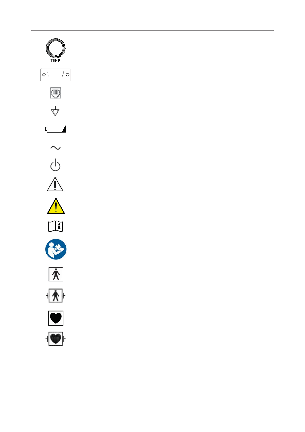
Socket for TEMP Sensor (Type CF applied part)
RS232 Interface (DB9 or D-Sub)
RJ45 Interface
Equipotential Grounding
Battery check
Alternating Current (a.c.)
Stand-by
Caution, consult ACCOMPANYING DOCUMENTS
Warning
Operating instructions
IPX1
IPX8
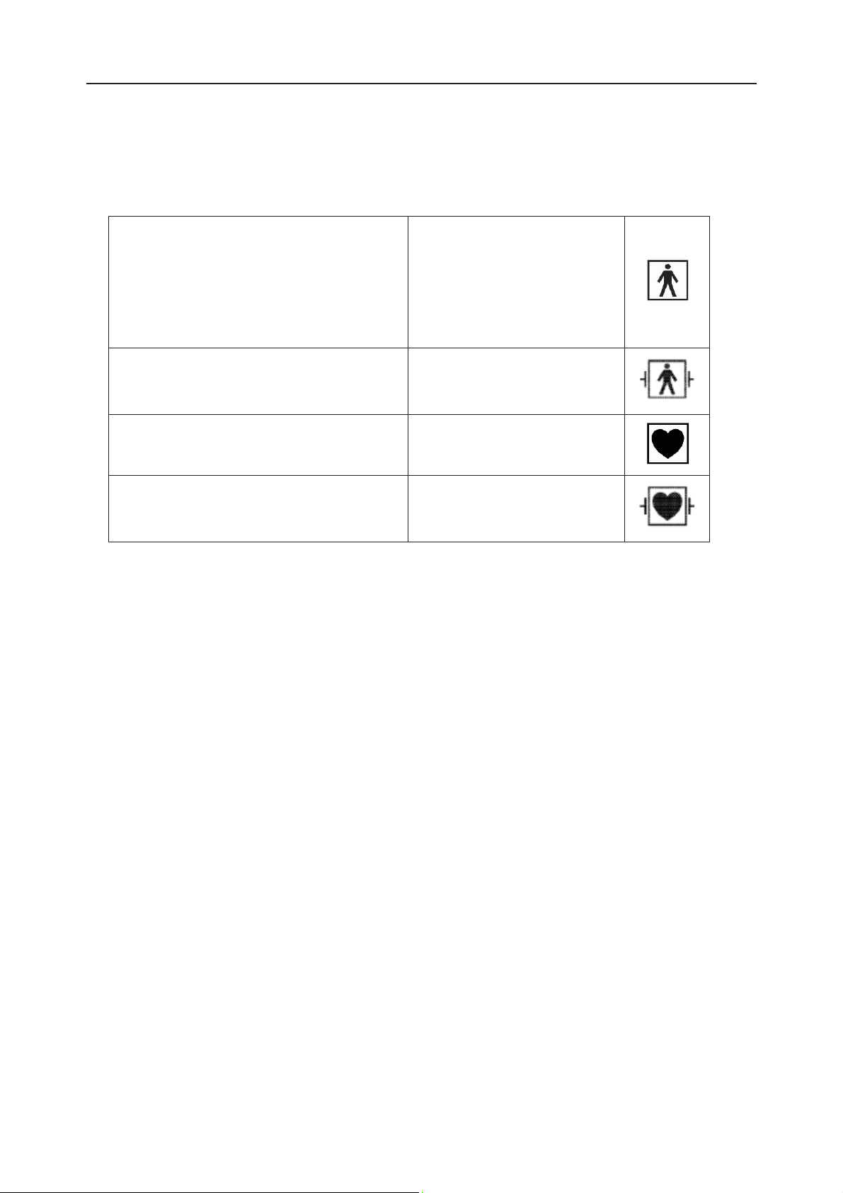
Follow instructions for use
Type BF applied part
Defibrillation-proof type BF applied part
Type CF applied part
Defibrillation-proof type CF applied part
Protected against vertically falling water drops
Protected against the effects of continuous immersion in water
- 12 -
Page 24
F Series Fetal & Maternal Monitor User Manual Safety Guide
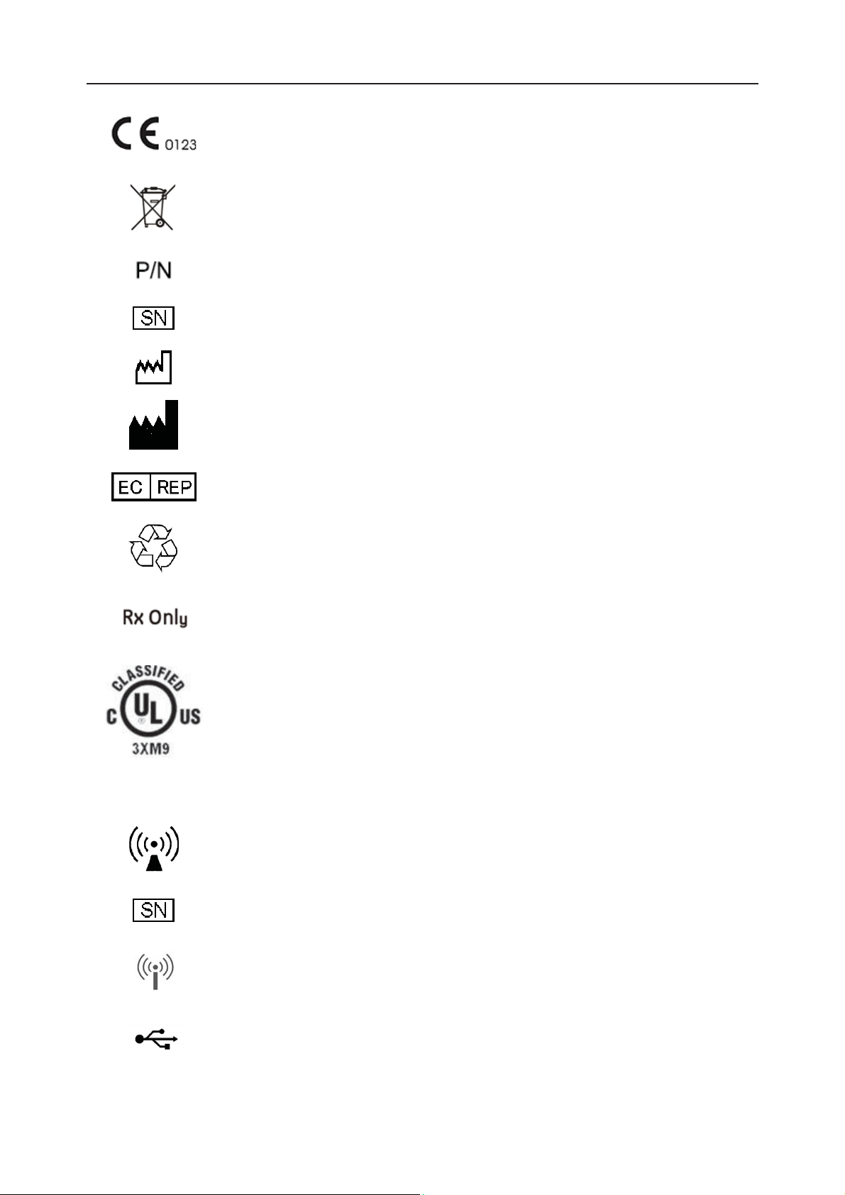
CE marking
Disposal method
Part Number
Serial Number
Date Of Manufacture
Manufacturer
Authorized Representative in the European Community
General symbol for recovery/recyclable
Caution: Federal (U.S.) Law restricts this device to sale by or on the order of
a physician
With respect to electrical shock, fire and mechanical hazards only in
accordance with UL 60601-1and CAN/CSA C22.2 No. 601.1
FTS-3 Fetal Telemetry System
Non-ionizing electromagnetic radiation
Serial Number
Wireless Transducer Working Indicator
USB Port (Reserved)
- 13 -
Page 25

F Series Fetal & Maternal Monitor User Manual Safety Guide
Ethernet Port (Reserved)
Channel Adjustment
- 14 -
Page 26

F9, F9 Express Fetal & Maternal Monitor User Manual Installation Guide
Chapter 2 Installation Guide
NOTE:
Installation must be carried out by qualified personnel authorized by the manufacturer.
2.1 Opening and Checking Package
Visually examine the package prior to unpacking. If any signs of mishandling or damage are
detected, contact the carrier to claim for damage.
Open the package; take out the monitor and accessories carefully. Keep the package for possible
future transportation or storage. Check the components according to the packing list.
Check for any mechanical damage.
Check all the cables and accessories.
If there is any problem, contact us or your local distributor immediately.
2.2 Installing Battery
WARNING
Switch off the monitor and unplug it before installing or removing the battery.
If your monitor has been configured with a rechargeable lithium-ion battery, follow these steps to
install the battery:
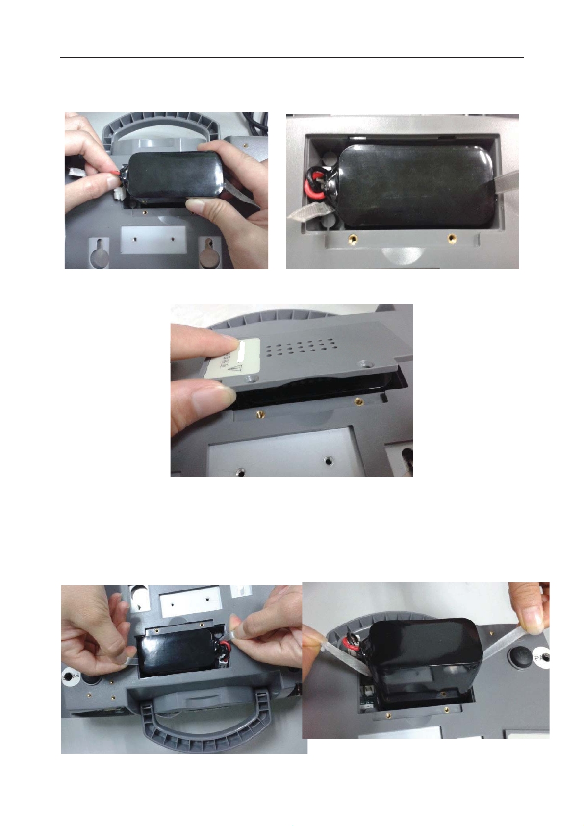
(1) Battery Installation
1) Carefully place the monitor upside down on a flat surface covered with cloth or other type of
protecting pad.
2) Remove the screws of the battery compartment using a cross-head screw driver. Remove the
battery compartment cover.
- 15 -
Page 27
F9, F9 Express Fetal & Maternal Monitor User Manual Installation Guide
3) Take the battery out from package. Put the battery and the cables into the battery
compartment and insert the cable connector into the socket.
4) Shut the battery compartment cover and fix the screws.
(2) Battery Removal
Fold the LCD display completely flat before turning the monitor upside down. Remove the
battery in reverse order. To remove the battery, hold the two bands of the battery tight, shake it
loose and pull it out with force.
- 16 -
Page 28

F Series Fetal & Maternal Monitor User Manual Installation Guide
NOTE:
1 If a rechargeable battery is outfitted, charge it fully each time after using the device to
ensure the electric power is enough.
2 After the device is transported or stored for a long time, charge the battery fully before
use. Connecting to power supply will charge the battery no matter if the monitor is
powered on.
3 Do not pull the battery cables, or the battery may become damaged.
2.3 Installing Monitor
The monitor can be placed on a flat surface, or be installed on a wall or a trolley. The service
engineer should install the monitor properly.
2.4 Connecting Power Cable
Make sure the AC power supply of the monitor complies with the following specification:
100V-240V~, 50Hz/60Hz.
Apply the power cable provided with the monitor. Plug one end of the power cable to the
power socket of the monitor. Connect the other end to a three-slot power output special for
hospital usage.
The equipotential grounding terminal is provided for the connection of a potential
equalization conductor. Therefore, it is recommended to connect the grounding terminal of
the monitor and the power outlet with the grounding wire, making sure the monitor is
grounded.
WARNING
If the protective grounding (protective earth) system is doubtful, the power of the monitor
must be supplied by internal power supply only.
NOTE:
1 Make sure the monitor and the power outlet are placed at a place where it is easy to
connect and disconnect the power cord.
2 When the supply mains is interrupted, the device switches to internal power supply
and operates normally if the battery is installed. If the battery is not installed, the
monitor shuts down and resumes the previous settings at the subsequent operation.
- 17 -
Page 29
F Series Fetal & Maternal Monitor User Manual Monitor and Accessories
p
Chapter 3 Monitor and Accessories
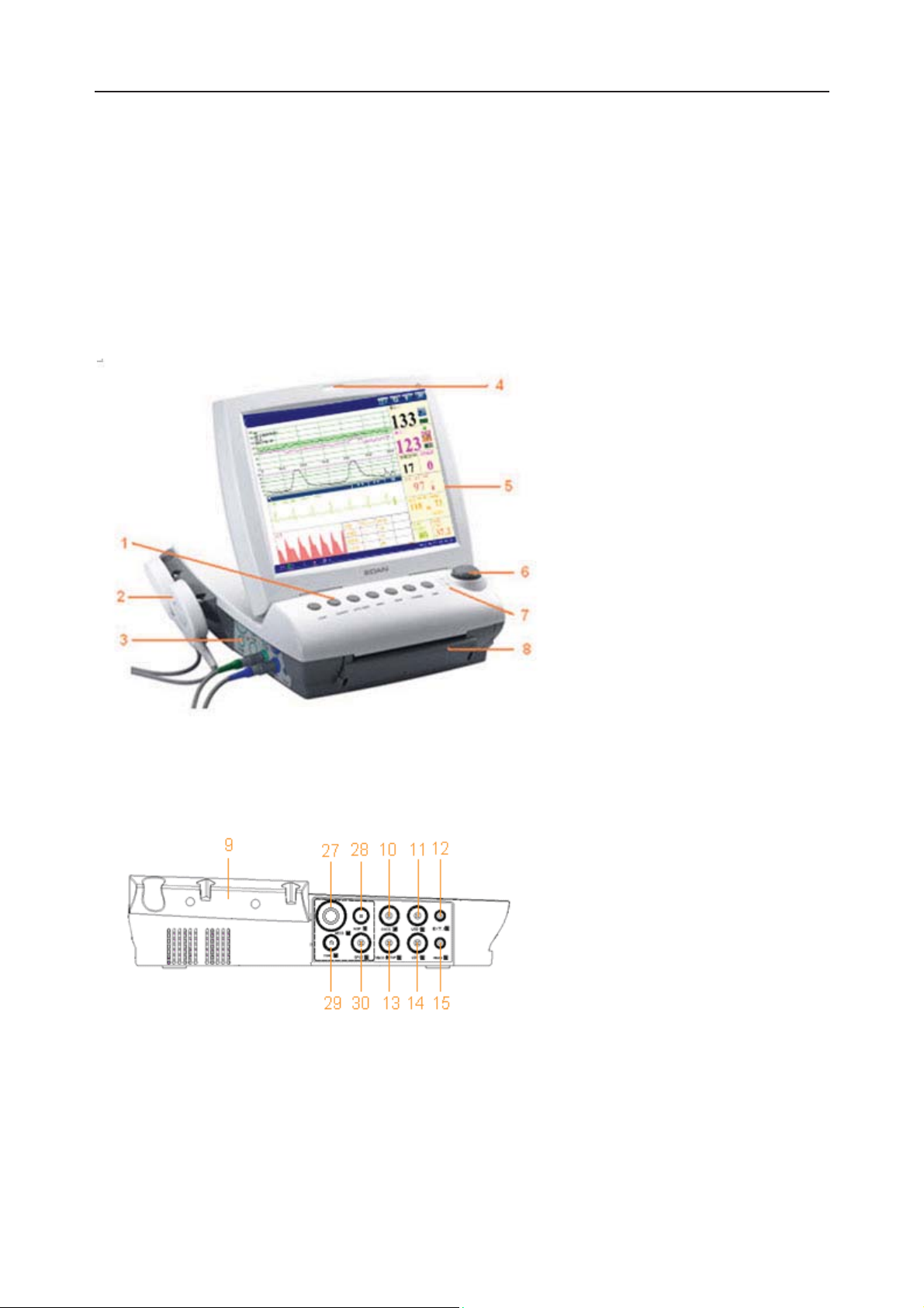
3.1 Overview
NOTE:
F6/F6 Express differs from F9/F9 Express in LCD size. This manual takes pictures and
interfaces of F9/F9 Express as an example, and they may look slightly different from
your model.
1 Keys
2 Transducer
3 Sockets
4 Alarm Indicator
5 Display Screen
6 Control Knob
7 Charge, AC, Power Indicator
8 Paper Drawer
Figure 3-1 Appearance (for reference only)
Figure 3-2 Left Panel
9 Transducer Holder
10 DECG Socket
11 US2 Socket
12 EXT.1 Socket
13 TOCO/IUP Socket
14 US1 Socket
15 MARK Socket
27 MECG Socket
28 NIBP Socket
29 TEMP Socket
30 S
O2 Socket
- 18 -
Page 30
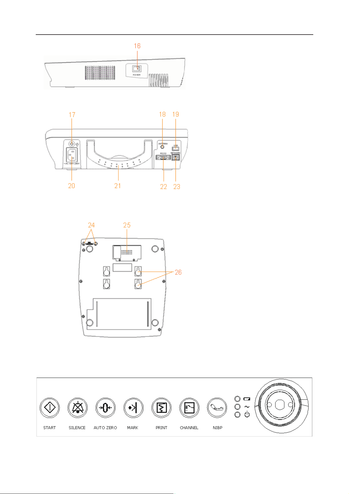
F Series Fetal & Maternal Monitor User Manual Monitor and Accessories
6
16 POWER Switch
Figure 3-3 Right Panel
17 Equipotential Grounding
Terminal
18 Antenna (Not applicable)
19 USB Socket (Not applicable)
20 Power Socket
21 Handle
Figure 3-4 Rear Panel
Figure 3-5 Bottom Panel
22 DB9 Socket
23 RJ45Socket
24 Fuses
25 Battery Compartment
2
Wall-mounting Holes
3.1.1 Keys and Control Knob
Figure 3-6 Keys and Control Knob
- 19 -
Page 31

F Series Fetal & Maternal Monitor User Manual Monitor and Accessories
The Monitor is a user-friendly device with operation conducted by a few keys on the front panel
and the control knob. Their functions are as follows:
(1)
*START
Function: Start monitoring or return to the main interface
Press this key to start monitoring (on the main interface) or return to main interface (in maternal
information inputting menu or setup menus).
(2) SILENCE
Function: Silence/reset
Press this key to disable the current auditory alarm manifestation, and re-enable the monitor’s
response to new abnormal patient condition.
(3) AUTO ZERO
Function: TOCO zero
Adjust the external TOCO contractions trace/value to preset unit (external monitoring
contractions) or the IUP trace/value to reference point 0 (internal monitoring contractions).
(4) MARK
Function: Record an event.
Press this key to make an event mark.
(5) PRINT
Function: Start / stop printing
Press this key to toggle between starting and stopping printing.
(6)
*CHANNEL
Function: Switch the channels
Press this key to toggle the FH sound between US1 channel and US2 channel.
(7) NIBP
Function: Start or stop a NIBP measurement.
Press this key to inflate the cuff and start a NIBP measurement. During the measuring process, press
this key to cancel the measurement and deflate the cuff.
- 20 -
Page 32

F Series Fetal & Maternal Monitor User Manual Monitor and Accessories
This function is only available on F6 Express and F9 Express.
(8) CONTROL KNOB
Function: Adjust volume, setup and review control.
It can be pressed like other keys and be rotated clockwise or counterclockwise. All the operations
on the screen or in the menu are completed by using the control knob.
The highlighted rectangular mark on the screen that moves with the rotation of the control knob is
called “cursor”. Operations can be performed in the position on the screen where the cursor stays.
When the cursor is located on a certain item, you can press the control knob to open its submenu
or confirm the operation. Press the control knob again, and the cursor will be able to move around
on the interface/menus.
Operation Procedure:
a) Rotate the control knob to move the cursor to the item you want;
b) Press the control knob;
c) One of the following three results will be achieved:
A menu pops up on the screen, or the menu is replaced by a new one;
A submenu with several options appears on the right of the item. If this item has more
than 8 options, they will be displayed in more than one page. Select PREV to switch to
the previous page, or select NEXT to switch to the next page.
The function operates immediately.
NOTE:
1 The word “select” hereinafter stands for rotating the control knob cursor to an item
and then pressing the knob.
2 If the key sound is enabled, the monitor gives a normal key sound when the operation
is valid, and gives a sharp “Di” sound when the operation is invalid.
CAUTION
This monitor is a normal medical device. Please avoid violent operations such as
continuously pressing the keys or control knob.
3.1.2 Indicators
There are four groups of indicator on top of the screen and the front panel. From the top down
they are: alarm indicator, CHARGE indicator, AC indicator and Power indicator.
- 21 -
Page 33

F Series Fetal & Maternal Monitor User Manual Monitor and Accessories
Indicator Status of Indicator Meaning
Alarm
Indicator
Flash or light up in yellow An alarm is active.
Off No alarm is active.
On The battery is being charged.
Charge
Indicator
Off
On
AC
Indicator
Off
On The monitor is powered on.
Off The monitor is powered off.
Power
Indicator
3.2 Accessories
3.2.1 Ultrasound (US) Transducers
No battery or the battery is fully
charged.
The monitor is connected to AC
power supply.
The monitor is not connected to AC
power supply.
1
Figure 3-7 US Transducers
3.2.2 TOCO Transducers
1
3
2
1 US Transducer Sensor
2 Transducer Cable
3 Transducer Connector
1 TOCOS Transducer Sensor
(Blue Labeled)
2 Transducer Cable
3 Transducer Connector
3
Figure 3-8 TOCO Transducers
- 22 -
Page 34

F Series Fetal & Maternal Monitor User Manual Monitor and Accessories
r
3.2.3 Belt
Figure 3-9 Belt
3.2.4 Remote Event Marker
1
Figure 3-10 Remote Event Marker
3.2.5 DECG Cable
1
1 Marker Plug
2 Press Key
2
1 DECG Cable Plug
2 DECG Cable Connecto
2
Figure 3-11 DECG Cable
- 23 -
Page 35

F Series Fetal & Maternal Monitor User Manual Monitor and Accessories
3.2.6 Fetal Spiral Electrode
Figure 3-12 Fetal Spiral Electrode
1 Reference Electrode 2 Drive Tube 3 Guide Tube
4 Drive Handle 5 Handle Notch 6 Electrode Wire
7 Safety Cap
3.2.7 IUP Cable
1
Figure 3-13 IUP Connecting Cable Figure 3-14 IUP Cable
1 Interface to IUP Cable 2 Connecting plug
3 Interface to IUP Catheter 4 Interface to Connecting Cable
2
3
4
- 24 -
Page 36

F Series Fetal & Maternal Monitor User Manual Monitor and Accessories
r
p
r
3.2.8 IUP Catheter
1 Interface to IUP Cable
1
3.2.9 ECG Cable
1
Figure 3-15 IUP Catheter
3
2 Cathete
2
1 ECG Connector
2 ECG Fastener
3 Lead Wire
2
3.2.10 SpO2 Sensor
Figure 3-16 3-Lead ECG Cable
1
Figure 3-17 SpO2 Sensor
1 SpO2 Sensor
O
2 S
2
Connecto
- 25 -
Page 37

F Series Fetal & Maternal Monitor User Manual Monitor and Accessories
3.2.11 NIBP Cuff
2
1 NIBP Cuff
Figure 3-18 NIBP Cuff Figure 3-19 Cuff Extension Tube
3.2.12 TEMP Sensor
1
2 Cuff Extension Tube
1 TEMP Sensor
2 TEMP Connector
Figure 3-20 TEMP Sensor
- 26 -
Page 38

F Series Fetal & Maternal Monitor User Manual Monitor and Accessories
3.3 Screen
3.3.1 Main Interface
Message
Window
Trace/Menu
Window
Numeric
Window
Status Window
Figure 3-21 Main Interface
*Background Color Switch
The main interface of the monitor displays numbers, traces, menus and monitor status
information. The screen background color has four choices: black, green, orange and blue.
To change the screen color,
1 Select the setup key
2 Select General > Screen Color.
3 Select the required color.
4 Select OK.
According to the content, the main interface is divided into four windows:
on the main interface.
According to the content, the main interface is divided into four windows: (1) Message Window
(2) Trace/ Menu Window (3) Numeric Window (4) Status Window.
- 27 -
Page 39

F Series Fetal & Maternal Monitor User Manual Monitor and Accessories
(1) Message Window
a b c d e
a)
:
Alarm messages displaying area. When an alarm is active, the message will be displayed
here in yellow. Patient alarms will be displayed on the left and technical alarms in the center.
b)
: Paper advancing key. Select this key to advance the paper for 8 cm (PHILIPS
paper) or 7 cm (GE paper).
c)
: Display mode switch. F6 Express and F9 Express monitors have three display
modes: maternal-fetal display mode, fetal display mode and maternal display mode. Select
this key, and the display mode will switch to the next one in order.
d)
: Mat. Info key. Select this key to open maternal information menu for inputting or
changing the patient’s ID and name.
e)
: Setup key. Select this key to open setup main menu.
(2) Trace/Menu Window
The trace/menu window occupies most space of the screen. During monitoring or reviewing, it
displays traces; during setting, it displays setup menus.
The background pane bar supports two standards: 30 ~ 240 (American standard) and 50 ~ 210
(International standard).
The green band in between the fetal heart rate panes indicates the preset alarm range (the top
edge is not higher than 180 and the bottom edge is not lower than 100). It makes it easy to
observe if the FHR exceeds the normal range. So you can easily tell if the fetal heart rate is too
low or too high.
(3) Numeric Window
The fetal monitoring numerics and maternal vital signs are displayed here.
When the monitor is connected to the FTS-3 system, the signal strength
and battery level
of the wireless transducers are displayed.
- 28 -
Page 40

F Series Fetal & Maternal Monitor User Manual Monitor and Accessories
(4) Status Window
f g h i j k l m n o p
f) Power indicator
- AC power supplied.
- no AC power supplied.
g) Battery indicator
The battery is loaded into the monitor with 100% capacity
75% capacity
50% capacity
25% capacity
The battery is almost depleted and needs to recharge immediately.
No battery is loaded.
h) Network connection indicator and device no.
- the monitor is online.
- the monitor is offline.
NOTE:
The network connection indicator is not available if the net version is Insight or
Philips.
i) Audio alarm indicator
- the audible alarm is switched on.
- 29 -
Page 41

F Series Fetal & Maternal Monitor User Manual Monitor and Accessories
- the current audible alarm is switched off infinitely.
- the current audible alarm is switched off temporarily.
j) Recorder status indicator
- the recorder is in the process of printing.
- no printing is going on.
- Print speed.
k)
l)
m)
- Print remaining time.
- Monitoring timer. It indicates the duration of the current monitoring, and
zeroes when the START key is pressed.
n) - FTS-3 system working channel
o) FTS-3 Base Station Battery indicator
The battery is loaded into the base station with 100% capacity
75% capacity
50% capacity
25% capacity
The battery is almost depleted and needs to recharge immediately.
When there is no battery indicator, it indicates that no battery is installed in the base station.
p) The date and time of the monitor.
3.3.2 Setup Interface
The setup menu is provided to change the monitor configurations and monitoring settings. Press
the Setup key on the main interface to open this menu.
- 30 -
Page 42

F Series Fetal & Maternal Monitor User Manual Monitor and Accessories
Setup Items
Function description
Software Version
Figure 3-22 Main Setup Menu (F9 Express)
In the setup main menu, you have access to all the items other than System. You can select EXIT
to exit from this menu.
The items in this main menu all have submenu(s). To confirm the setting changes in the
submenus, you need to select OK to exit. If you don’t want to store the new settings, select
Cancel, or press the START key to return to the main interface. If no operation is performed in
30 seconds, the menu will return to the upper directory. The change will not be stored.
Once you select OK to confirm the setting changes, the new settings will be stored in the
monitor’s long-term memory. If the monitor is switched on again after being switched off or a
power loss, it will restore the new settings. The setting does not take effect if the system exits
automatically or is shutdown before OK is selected.
For your reference, when the cursor is located at an item in this menu, the monitor provides a
brief function description of this item in a pane with blue frame under the items. For example, the
cursor is located at “System” in the illustration above. Correspondingly, its function “Set system
items of the monitor” is issued in the blue frame pane.
3.3.3 Touch Screen
As an option, some of F9 and F9 Express may have been configured with a touch screen.
The touch screen is easy to use and operate. It works as a smart control knob. All the operations
of the control knob can be done by gently touching the corresponding position on the screen.
When the touch screen is configured, touching the corresponding menu item is equal to rotating
- 31 -
Page 43

F Series Fetal & Maternal Monitor User Manual Monitor and Accessories
the control knob to this item and then pressing it. In the same way, one of the three results with
the control knob will be achieved.
On the main interface, the symbols
item. Touch the
leftwards. While touching the
symbol to increase the numeric, move to the previous item or move
will decrease the numeric, move to the next item or move
and might appear right next to the highlighted
rightwards.
To exit from the submenu, you should touch the item again or touch any place outside the area of
the options.
NOTE:
When touching an item, place the finger or the stylus pen within this item’s cursor pane
to ensure the operating validity. A key sound is heard corresponding to every valid touch,
if the key sound is enabled.
- 32 -
Page 44

F Series Fetal & Maternal Monitor User Manual Alarms
Chapter 4 Alarms
4.1 Alarms Classification
The monitor has two types of alarm: patient alarm and technical alarm.
Patient alarms indicate the situation of vital sign exceeding its configured limit. Audible alarms
and visual alarms can be disabled excluding ASYSTOLE alarm. The adjustable alarm limits
determine the conditions that trigger the alarm.
Technical alarms indicate that the monitor can not measure and therefore can not detect critical
patient conditions reliably. They cannot be disabled.
In terms of severity, the alarms are divided into three levels: high, medium and low. High level
alarm indicates the condition where the patient’s life is endangered; it is a severe warning, labeled
with the symbol ***; Medium level alarm is a moderate warning, labeled with the symbol **;
low level alarm is a general warning.
The high level alarms have highest priority, and the medium level alarms take the second place. If
more than one type of alarms is active at the same time, the monitor sounds an audible indicator
for the higher level alarms.
The alarm levels are preset, and can not be changed.
4.2 Audible Alarm
If the audible alarm is not disabled, the alarm indicator displays . When an alarm is active,
the monitor gives out an alarm sound (the sound pressure range is 45dB ~ 85dB).
High level alarm: a “Do” tone is repeated three times, and then pauses for 3 seconds.
Medium level alarm: a “Do” tone is repeated three times, and then pauses for 5 seconds.
Low level alarm: a “Do” tone is issued, and then pauses for 20 seconds.
Press the SILENCE key, the current audible alarm toggles between on and off (temporarily or
infinitely, you can change the setting).
If the current audible alarm is temporarily disabled, the alarm indicator displays
remaining time on the right. The audible alarm is enabled again when the time is out, or when the
SILENCE key is pressed.
, with a
If the current audible alarm is infinitely disabled, the alarm indicator displays
The audible alarm is enabled again when the SILENCE key is pressed.
If Alarm Reset is enabled (see 4.8 Pausing or Resetting the Alarm), and you press the SILENCE
key to disable an audible alarm, the alarm indicator will display
the monitor will enable the audible alarm again automatically.
During the silence period, the alarm messages are displayed and the alarm indicator lights up as
usual. You can press the SILENCE key again to enable the audible alarm.
- 33 -
. When other alarms present,
(flashing).
Page 45

F Series Fetal & Maternal Monitor User Manual Alarms
WARNING
1 Do not rely exclusively on the audible alarm system for patient monitoring.
Adjustment of alarm volume to a low level or off during patient monitoring may result
in patient danger. Remember that the most reliable method of patient monitoring
combines close personal surveillance with correct operation of monitoring
equipment.
2 When the sound pressure of audible alarm is equivalent to the ambient noise, it may
be difficult for the operator to distinguish the audible alarm.
3 Do not disable the audible alarm infinitely for the condition where the patient’s safety
may be endangered.
NOTE:
After you enable the audible alarm again, whether the alarm sound still exists depends
on whether the alarm persists.
4.3 Visual Alarm
When an alarm is active,
- Alarm indicator: the alarm indicator lights up:
Alarm Category Indicator Color Flashing Frequency Duty Cycle
High level alarm red 1.4Hz to 2.8Hz 20% to 60% on
Medium level alarm yellow 0.4Hz to 0.8Hz 20% to 60% on
Low level alarm yellow Constant (on) 100% on
- Alarm message: the alarm message appears in the message window of the main interface in
yellow, with patient alarms on the left and technical alarms in the middle.
- Flashing numeric: the numeric of the measurement flashes in grey with a frequency of 2Hz.
When more than one alarm is active, the alarm messages appear in the same area in succession.
The patient alarm messages are displayed either:
in text form, for example “** FHR2 LOW”; or
in numeric form, for example “** FHR2 115 < 120”; ** indicates this is a medium level
alarm event; the first number is the current measurement result; the second number is the
preset alarm limit.
The technical alarm messages are displayed in text form, for example “Fetus EQUIP MALF”.
WARNING
Setting alarm limits to extreme values may cause the alarm system to become
ineffective. It is recommended to use the default settings.
- 34 -
Page 46

F Series Fetal & Maternal Monitor User Manual Alarms
4.4 Choosing the Alarm Display Form
You can change the patient alarm display form,
1 Select the setup key
2 Select Alarm. On the displayed Password box, enter 9999, then select Enter.
3 Select Message Form.
4 Select Text (default) or Numeric.
5 Select OK.
on the main interface.
4.5 Changing the Alarm Volume
You can change the alarm volume,
1 Select the setup key
2 Select Alarm. On the displayed Password box, enter 9999, then select Enter.
3 Select Alarm Volume.
4 Select Low (default), Medium or High.
on the main interface.
5 Select OK.
4.6 *Choosing Alarm Silence Duration
You can change the alarm silence duration,
1 Select the setup key
2 Select Alarm. On the displayed Password box, enter 9999, then select Enter.
3 Select Silence Duration.
4 Select Infinite, 1 min (default), 2 min or 3 min.
5 Select OK.
on the main interface.
4.7 Choosing Signal Loss Delay
When the fetal signal is lost and this condition continues for a certain time, the monitor issues a
technical alarm. This time (signal loss delay) is adjustable. To change the signal loss delay,
- 35 -
Page 47

F Series Fetal & Maternal Monitor User Manual Alarms
1 Select the setup key on the main interface.
2 Select Alarm. On the displayed Password box, enter 9999, then select Enter.
3 Select Signal Loss Delay.
4 Select 0 (default) ~ 300 seconds.
5 Select OK.
4.8 Pausing or Resetting the Alarm
You can enable the function of pausing or resetting audible alarms.
1 Select the setup key
2 Select Alarm. On the displayed Password box, enter 9999, then select Enter.
3 Select Audio Alarm.
4 Select Alarm Pause (default) or Alarm Reset.
If Alarm Pause is selected: When the monitor gives out alarm sound and you press the
SILENCE key, the alarm indicator displays
If Alarm Reset is selected: When the monitor gives out alarm sound and you press the
SILENCE key, the alarm indicator displays
other alarms present, the monitor will enable the audible alarm again automatically.
5 Select OK.
on the main interface.
, and the alarm sound is muted.
, and the alarm sound is muted. When
4.9 *Reviewing Alarms
An alarm reviewing menu cannot only record the immediate alarm messages with date and time
information, but also record the historically physiological alarm and signal overlap alarm
messages with date and time information.
The monitor can display a maximum of 100 immediate alarm messages. When the storage is full,
it will delete the earliest alarm message automatically to store the new one.
The monitor can display a maximum of 800 historically physiological alarm and signal overlap
alarm messages. When the total number exceeds 800, the alarms messages cannot be stored.
Select the alarm reviewing key
When you review the traces with the word REVIEW shown in the background, the alarm
reviewing menu displays historic alarm review. Otherwise, it displays the immediate alarm
review.
in the message window to open this menu.
- 36 -
Page 48

F Series Fetal & Maternal Monitor User Manual Alarms
Each page displays 10 alarm records. The page mark “1/6” informs you that there are 6 pages and
the present one is page 1.
To review more records, select the alarm list and then rotate the control knob to switch to the
previous or next page.
Select OK to exit from this menu.
When a new monitoring starts, or after the monitor is switched off, the alarm messages will be
cleared.
NOTE:
You can select Main Menu > General > Review Alarms to set up On (by default) or
OFF. When the alarm review is enabled, the icon will appear in the main interface.
4.10 Alarm Treatment Measures
During monitoring, make sure there is at least one physician in the area where the alarm sound
can be heard or the alarm messages can be seen, so necessary measures can be taken when an
emergency occurs.
When the monitor gives out an alarm and catches your attention, you should:
- Check the patient’s condition.
- Identify the cause of the alarm.
- Silence the alarm if necessary.
- Check if the alarm is terminated when the alarm condition is solved.
When the monitored parameter(s) come(s) back within the adjusted limits, or if the abnormal
technical condition does not exist any longer, the monitor stops giving out the alarm.
- 37 -
Page 49

F Series Fetal & Maternal Monitor User Manual Alarms
4.11 Testing Alarms
To test the functions of visible and audible alarms, do the following:
1 Switch on the monitor.
2 Enable the alarm.
3 Set the alarm limits to a small range.
4 Stimulate a signal that is higher than the upper limit or lower than the lower limit. Or
disconnect one of the plugs.
5 Verify if the visible and audible alarms are working properly.
4.12 Patient Alarm Defaults
Alarm Setting Options Default
High Level
ASYSTOLE On (not adjustable) On
Asystole Alarm Delay 0 second (not adjustable) 0 second
Asystole Alarm Level High (not adjustable) High
Medium Level
FHR1/FHR2 Alarm On, Off On
FHR1/FHR2 Low Alarm Limit 60 bpm ~ 205 bpm, in increments of 5 110 bpm
FHR1/FHR2 High Alarm Limit 65 bpm ~ 210 bpm, in increments of 5 160 bpm
FHR1/FHR2 Alarm Delay 0 ~ 30 second(s), in increments of 5 10 seconds
FHR1/FHR2 Alarm Level Medium, not adjustable Medium
HR Alarm On, Off On
HR Low Alarm Limit 30 bpm ~ 239 bpm, in increments of 1 50 bpm
HR High Alarm Limit 31 bpm ~ 240 bpm, in increments of 1 120 bpm
HR Alarm Delay 0 second, not adjustable 0 second
HR Alarm Level Medium, not adjustable Medium
SpO2 Alarm On, Off On
SpO2 Low Alarm Limit 50% ~ 99%, in increments of 1 90%
SpO2 High Alarm Limit 51% ~ 100%, in increments of 1 100%
- 38 -
Page 50

F Series Fetal & Maternal Monitor User Manual Alarms
SpO
Alarm Delay 0 second, not adjustable 0 second
2
SpO2 Alarm Level Medium, not adjustable Medium
SYS Alarm On, Off On
SYS Low Alarm Limit 40 mmHg ~ 269 mmHg, in increments of 1 90 mmHg
SYS High Alarm Limit 41 mmHg ~ 270 mmHg, in increments of 1 160 mmHg
SYS Alarm Delay 0 second, not adjustable 0 second
SYS Alarm Level Medium, not adjustable Medium
DIA Alarm On, Off On
DIA Low Alarm Limit 10 mmHg ~ 214 mmHg, in increments of 1 50 mmHg
DIA High Alarm Limit 11 mmHg ~ 215 mmHg, in increments of 1 90 mmHg
DIA Alarm Delay 0 second, not adjustable 0 second
DIA Alarm Level Medium, not adjustable Medium
TEMP Alarm On, Off On
TEMP Low Alarm Limit 0 ºC ~ +49.9 ºC, in increments of 0.1 +36.0 ºC
TEMP High Alarm Limit +0.1 ºC ~ +50.0 ºC, in increments of 0.1 +39.0 ºC
TEMP Alarm Delay 0 second, not adjustable 0 second
TEMP Alarm Level Medium, not adjustable Medium
NOTE:
The upper limit must be higher than the lower limit. When setting the upper limit, you do
not have access to the options that are lower than the preset lower limit, and vice versa.
- 39 -
Page 51

F Series Fetal & Maternal Monitor User Manual Printing
Chapter 5 Printing
5.1 *Function Description
The built-in thermal recorder applied in the monitor supports both the American and international
standard wide recorder paper. It prints continuous traces synchronously along with marks.
The monitor supports some other functions listed below:
Auto start printing: If the function is enabled, the recorder starts printing automatically
when new monitoring starts (the START key is pressed). Otherwise you have to press the
PRINT key to start printing.
Printing timer: The printing timer determines the elapsed time for each print. This time is
adjustable. Refer to 5.2.3 Changing the Print Timer.
Remaining time indicating: If the printing timer is set, a process indicator
appears in the status window after printing starts, with the remaining time shown in it. When
the time is up, the monitor gives three “Do” tones and flashes the indicator.
Fast printing: The recorder prints the data saved in the monitor at a high speed (up to
15mm/s).
Data Caching: When the paper drawer runs out of paper or when it is open, the recorder
stops printing. The data from this time on (at most 60 minutes) will be temporarily saved in
the internal memory. When new paper is loaded and/or the drawer is closed, the saved data
will be printed out at a high speed. When the saved trace has been printed out, the recorder
switches back to continue printing the current data at the normal speed automatically.
NOTE:
1 When the monitor is switched off, the data in the internal memory will be lost.
2 If a printing timer is set, and the time is out when the paper runs out, the CTG
analysis result may disaccord with the printout. Therefore, reload the paper in
time to avoid paper lack.
FHR2 offset: You can set the offset of the FHR2 trace to separate the two FH traces on the
screen and the recorder paper. Refer to 7.4.4 Changing FHR2 Offset.
Print self-check: The recorder prints a baseline for self checking when the monitor is
switched on.
Paper advance: When printing stops, press the paper advancing key to advance the
paper, making sure the paper has a perforation outside the drawer and is easy to be torn off.
NOTE:
The paper advancing key is invalid in the process of printing and paper advancing.
- 40 -
Page 52

F Series Fetal & Maternal Monitor User Manual Printing
5.2 Printing Configuration
NOTE:
All the parameters should be well configured before printing starts. You can not change
the configuration in the process of printing.
5.2.1 Switching Auto Start Printing On or Off
You can switch auto start printing on or off:
1 Select the setup key
2 Select Start Monitoring > PRINT.
3 Select ON or OFF (default).
4 Select OK.
on the main interface.
5.2.2 *Choosing the Paper Speed
You can choose a paper speed of 1 cm/min, 2cm/min or 3cm/min:
1 Select the setup key
2 Select Recorder > Print Speed.
3 Select 1 cm/min, 2 cm/min or 3 cm/min (default).
4 Select OK.
NOTE:
Different paper speed setting causes different FHR trace appearance on the record
paper. To avoid misinterpretation, we recommend you to set all monitors in your
on the main interface.
institution to the same paper speed.
5.2.3 *Changing the Print Timer
You can choose different time lengths for the print timer:
1 Select the setup key
2 Select Recorder > Timer.
3 Set timer to 10 ~ 90 (minutes, the step is 5) or Infinite (default). For a fixed time, the
recorder stops when the time is up. For Infinite, there is no time limit. Whatever the setting
is, the recorder stops when this patient’s traces come to the end or if the PRINT key is
pressed in midway.
4 Select OK.
on the main interface.
- 41 -
Page 53

F Series Fetal & Maternal Monitor User Manual Printing
5.2.4 Switching Print Self-Check On or Off
You can switch on or off the print self-check feature:
1 Select the setup key
2 Select Recorder > Print Self-Check.
3 Select ON or OFF (default).
4 Select OK.
on the main interface.
5.2.5 Changing Printing End Volume
The monitor gives a tone when printing ends, and this tone volume is adjustable.
1 Select the setup key
2 Select Recorder > Print Ending Beep.
3 Select High, Low (default) or OFF.
4 Select OK.
on the main interface.
5.3 Understanding the Recorder Paper Printout
WARNING
1 If there is any discrepancy between the display and the printout, the printout should
prevail.
2 If the data is doubtful, clinicians should make diagnoses based on the real condition.
Figure 5-1 is an example of the recorder paper with traces. Comparing it with the monitor screen,
you can find this extra information on it:
- 42 -
Page 54

F Series Fetal & Maternal Monitor User Manual Printing
(1)
(2)
(3)
(7)
(8)
(9)
(10)
(11)
(12)
(13)
(4)
(14)
(5)
(6)
Figure 5-1 An example of recorder paper with traces
Item Information Description
1. Self-Check Trace
2. Paper Settings
3. Paper Type There are two types of paper: F9-G and F9-P.
4. Paper Style
5. FHR1 Mark The trace marked with “FHR1” is the FHR1 trace.
6. FHR2 Mark The trace marked with “FHR2” is the FHR2 trace.
The monitor prints a self-check trace after being switched on. It is
used to check if the recorder paper is properly loaded.
The paper settings of the monitor. It consists of the paper type and
paper style, e.g. “G 50-210”, indicating that the paper type is “F9-G”,
and the paper style is International. It is printed out to check if the
proper recorder paper is used.
The FHR pane range indicates the paper style.
American style: 30 ~ 240
International style: 50 ~ 210
7.
8. Smart Note The annotation of the event mark below.
9. HR Mark The trace marked with “HR” is the maternal HR trace.
Trace
Information List
A list of current date, time, print speed, ID, Name, FHR2 offset, HR,
SpO2, NIBP (including SYS and DIA) and TEMP is printed at the start
of the monitoring and every ten minutes afterwards.
- 43 -
Page 55

F Series Fetal & Maternal Monitor User Manual Printing
10. SpO
Mark The trace marked with “SpO2” is the maternal SpO2 trace.
2
11. NIBP
12. Page Mark
13.
CTG Analysis
Result
14. Alarm Message
In the real-time printing mode, each NIBP measurement result is
printed on the paper in the order of SYS/DIA.
Each recorder paper pack has 150 pages. When you notice the page
mark comes to the end, remember to load new paper in time.
The CTG analysis results of FHR1 and FHR2.
It indicates the physiological alarm message and signal overlap alarm
message.
- 44 -
Page 56

F Series Fetal & Maternal Monitor User Manual Pre-Monitoring Preparation
Chapter 6 Pre-Monitoring Preparation
6.1 Loading Recorder paper
CAUTION
1 Only use the recorder paper provided by the manufacturer, otherwise the recorder
may be damaged. This kind of damage is not covered by warranty.
2 Configured with different hardware, the monitor is compatible with both GE and
Philips recorder paper. However, the monitor is configured with only one type of paper
in the shipment. If you want to use the other type of paper, contact the manufacturer
for service first, otherwise trace excursion or paper jam may occur.
If the monitor is used for the first time or when the paper runs out, you should load paper.
1) Press the two latches on each side of the paper drawer at the same tine and slide the drawer
out carefully.
2) Take out the Z-fold thermosensitive paper and remove the wrapper.
3) Place the pack in the drawer, with the pane facing up and the FHR trace area on the left.
- 45 -
Page 57

F Series Fetal & Maternal Monitor User Manual Pre-Monitoring Preparation
4) Unfold two sheets from the top of the pack and pull the end of the paper out of the drawer
(make sure the pack in the drawer remains flat).
5) Slide the drawer in until both the latches are locked.
NOTE:
1 Be careful when inserting paper. Avoid damaging the thermosensitive print head.
2 Make sure the paper is evenly loaded in the drawer. Otherwise the data will be
inaccurate or paper jam will happen.
3 Only use the paper the manufacturer approved to avoid poor printing quality,
deflection, or paper jam.
4 Keep the drawer closed unless when loading paper or providing a service.
Removing Paper Jam
When the recorder does not function or sound properly, open the drawer to check for a paper jam.
Remove the paper jam in this way:
1) Cut the recorder paper from the paper drawer edge.
2) Through the hole on the bottom panel of the paper drawer, push the recorder paper up
with one finger. Remove the paper.
3) Reload paper and then close the drawer.
- 46 -
Page 58

F Series Fetal & Maternal Monitor User Manual Pre-Monitoring Preparation
6.2 Switching On
WARNING
1 Check if all the metal parts are linked to the protective earth cord and the cord is in
good condition before switching on the monitor.
2 If any sign of damage is detected, or the monitor displays some error messages, do
not use it on any patient. Contact biomedical engineer in the hospital or our service
engineer immediately.
Press the POWER switch on the right panel to switch on the monitor. The power indicator lights
up and a start-up music will be heard. You can operate the monitor after the main interface
appears.
You can choose to switch the start-up music on or off,
1 Select the setup key on the main interface.
2 Select General > Start-up Music.
3 Select ON (default) or OFF.
4 Select OK.
6.3 Checking Recorder Paper
The monitor provides the print self-check function to check if the recorder paper is correctly
loaded and set.
The recorder prints a baseline and paper settings after start-up (if Print Self-Check is ON).
Check if the paper settings match the paper being used (in the circled area below, P should
correspond to F9-P, and G to F9-G), and then observe the starts and ends of the printed baselines
(illustrated with the arrow). The starts and ends should be printed exactly on the edges of the pane
if the recorder paper is correctly loaded and set. If they do not comply with the edges, reload
paper or ask the service engineer to check the paper settings of the monitor.
- 47 -
Page 59

F Series Fetal & Maternal Monitor User Manual Pre-Monitoring Preparation
If the monitor does not print the baseline, switch on the Print Self-Check function and then
restart the monitor.
NOTE:
Make sure the paper is correctly loaded before the printing starts.
6.4 Adjusting Screen Angle
The angle between the screen and the top cover of the monitor is adjustable as needed, allowing it
to be mounted on a wall or placed on a flat surface.
Adjustment method:
Push the hook on top of the screen left to spring it open. Pull the screen forward to adjust to one
of the preset screen angles.
To bring the screen back to flat, pull it all the way forward and then push it back.
- 48 -
Page 60

F Series Fetal & Maternal Monitor User Manual Pre-Monitoring Preparation
6.5 Setting Date and Time
You can change the date and time of the monitor,
1 Select the setup key
2 Select Date And Time.
3 Set the year, month, date, hour, minute and second. The first three numbers are used to set
the year, month and date. Their orders vary with the preset Date Format below.
4 Select Date Format for the format of the date; there are three options: yyyy-mm-dd
(default), mm/dd/yyyy and dd/mm/yyyy.
5 Select OK.
You should set date and time information in advance. After this information is changed,
the monitor starts new monitoring with an auto ID. Therefore, we advise you to restart
the monitor after changing date or time information, and do not perform this operation
when monitoring is in process.
NOTE:
on the main interface.
CAUTION
The date and time remain in the monitor for at least two months after it is switched off.
You do not have to set date and time before monitoring each time.
6.6 Connecting Transducers
Check for visible damages of the transducers every time before connecting them to the monitor.
Pay special attention to the cracks on the transducers and cables before immersing them into
conductive fluid. If damage is found, replace them with good ones at once.
- 49 -
Page 61

F Series Fetal & Maternal Monitor User Manual Pre-Monitoring Preparation
When plugging transducers into the monitor, make sure the arrow symbol of the connector faces
up and put it into the socket.
When disconnecting a transducer, pinch the afterbody of the transducer plug and pull it out
slightly.
NOTE:
Never try to disconnect the transducer by pulling the cable directly.
6.7 Placing Accessories in the Holder
In order to protect the accessories, place the not-in-use accessories in the holder. The accessory
holder is on the left of the front panel. The first hole from the top is for the remote event marker,
and the rest two are for the transducers.
To place a transducer into the holder, hold the transducer on the edge, and then place the buckle
all the way into one of the holes on the holder. Make sure that the transducer cable is on the
bottom.
To place the remote event marker, put the small end of the marker into the hole as far as it can go.
- 50 -
Page 62

F Series Fetal & Maternal Monitor User Manual Pre-Monitoring Preparation
NOTE:
In the process of monitoring, the transducer that is placed in the holder may be affected
and thereby produces interfering signals. Therefore, when monitoring a patient, it is
recommended to remove or disconnect the transducer that is not in use.
6.8 Adjusting the Volume
The monitor automatically detects which channel the transducer is connected to. The
corresponding volume adjustment key of this channel displays
coming out from this channel; while the other one displays
. Press the CHANNEL key to switch the FH
sound to the other channel.
Adjust the default monitoring volume:
The FH volume returns to the default level after the START key is pressed. This default level is
adjustable. To change this level,
1 Select the setup key
2 Select Start Monitoring > Volume .
3 Select the volume from 1 ~ 10; the step is 1 and the default level is 3.
4 Select OK.
on the main interface.
, indicating the FH sound is
, for example:
*Adjust the real-time monitoring volume:
If the default volume level is not satisfactory during monitoring, you can adjust the real-time
volume of each channel.
1 Select the volume adjustment key
2 Rotate the control knob clockwise for one step, the volume increases by one level, there
are ten levels for your choice; the green pane of the volume level indicator
increases by one at every two steps; rotate the knob anticlockwise to decrease the volume.
3 Press the knob again to confirm the volume level.
on the main interface.
- 51 -
Page 63

F Series Fetal & Maternal Monitor User Manual Pre-Monitoring Preparation
*Adjust the key volume:
The volumes of pressing keys, rotating and pressing the control knob are also adjustable.
1 Select the setup key
on the main interface.
2 Select General > Key Volume.
3 Select Low (default), High or OFF.
4 Select OK.
- 52 -
Page 64

F Series Fetal & Maternal Monitor User Manual Fetal Monitoring
Chapter 7 Fetal Monitoring
WARNING
1 The monitor is not intended for use in intensive care units (ICU), operating rooms or
for home use.
2 Do not apply the monitor during electro-surgery or MRI; otherwise it might result in
harming the patient or the operator.
3 Always check if the alarm settings are appropriate for your patient before starting
monitoring.
7.1 Confirming Fetal Life
Fetal monitoring with ultrasound or DECG can not differentiate a fetal heart rate signal source
from a maternal heart rate source in all situations. These are some of the signal sources that might
be taken as FHR signal source by mistake:
- High maternal heart rate signal.
- Maternal aorta or other large vessels signals.
- Electrical impulse from the maternal heart transmitted through a recently deceased fetus.
- Movement of the deceased fetus during or following maternal movement.
So you need to confirm fetal life by other means before starting to use the fetal monitor, such as
using a fetoscope, stethoscope, Pinard stethoscope or obstetric ultrasonography.
7.2 Monitoring FHR with Ultrasound
The ultrasound monitoring is a method to obtain FHR on maternal abdominal wall. Place a US
transducer (Ultrasound transducer) on maternal abdomen. It transmits low energy ultrasound
wave to the fetal heart, and receives the echo signal.
WARNING
Make sure you have confirmed the fetal life by other means before using this monitor for
FHR monitoring.
7.2.1 Parts Required
1) US transducer 2) Aquasonic coupling gel 3) Belt
- 53 -
Page 65

F Series Fetal & Maternal Monitor User Manual Fetal Monitoring
7.2.2 FHR Monitoring Procedure
1) Placing Transducer Belt
Place the transducer belts across the bed, ensuring that the belt will be around the abdomen
when it is fastened. Lay the patient on the bed.
Alternatively, the patient can take a sitting position. Arrange the belt around her abdomen.
2) Determining the Transducer Position
- Determine the fetal position using Leopold’s maneuvers.
- Search for the location of the fetal heart using a stethoscope or a fetoscope. The best fetal
heart signal can be obtained through the fetal back.
- Place the transducer below the navel for head presentation and place the transducer above the
navel for breech presentation.
- During parturition, the fetal heart moves downward as the labor progresses. It is
recommended to move the transducer along with the fetus.
Fetal Heart
Pregnancy
Early Parturition
Late Parturition
Figure 7-1 Positioning Ultrasound Transducer (single fetus)
3) Acquiring Fetal Heart Signal
Apply a certain amount of acoustic gel on the transducer and move the transducer slowly around
the fetus site to even the gel. The best fetal heart signal can be obtained through the fetal back.
Find at least 2 or 3 sites, and choose the one where the clearest, most sonorous and steady fetal
heart sound is heard. When the transducer is connected correctly and communicated well, the
fetal heart signal indicator is full. If the signal is poor, the signal indicator shows as it is and no
FHR data are displayed. When you move the transducer on the abdomen, adjust the speaker
volume so that it can be clearly heard.
4) Fixing the Transducer
When you find clearest and most steady fetal heart sound, wrap the abdomen with the belt over
the transducer. Fix the transducer by pushing its buckle through the overlapping section of the
belt.
- 54 -
Page 66

F Series Fetal & Maternal Monitor User Manual Fetal Monitoring
Make sure the belt fits the patient snugly but comfortably. Meanwhile, fetus heart beat sound is
heard; the FHR trace and numeric are displayed. During long-time monitoring, the gel may dry
out as the transducer moves around. Add more gel in time if it is inadequate.
5) Confirming that the Fetus is the Signal Source
Ultrasound Doppler technology is utilized to observe the fetal heart rate externally, there are
possibilities that maternal heart rate signal is mistaken for FHR signal. It is highly
recommended to confirm that the fetus is the signal source continuously. You can feel the
maternal pulse at the same time.
If the maternal heart signal is misidentified as the fetal heart signal, Repositioning of the
transducer is needed.
NOTE:
1 Do not mistake the high maternal heart rate for fetal heart rate. The fetal pulse can be
distinguished from the maternal pulse by feeling the mother’s pulse during the
examination.
2 The best quality records will only be obtained if the probe is placed in the optimum
position. Positions with strong placental sounds or umbilical blood flow sound should
be avoided.
3 If the fetus is in the cephalic presentation and the mother is supine, the clearest heart
sound will normally be found on the midline below the umbilicus. During monitoring,
the patient’s prolonged lying in the supine position should be avoided owing to the
possibility of supine hypotension. Sitting up or lateral positions are preferable and
may be more comfortable.
4 It is impossible to examine FHR unless a clear fetal heart signal is detected.
5 During long-time monitoring, the gel may dry out as the transducer moves around.
Add more gel in time if it is inadequate.
6 When applied to the patient, the ultrasound transducer may warm slightly (less than
1°C (1.8ºF) above ambient temperature). When NOT applied, the ultrasound
transducer may warm slightly (less than 2°C (3.6ºF) above ambient temperature).
7.2.3 Switching FHR Alarm On or Off
Always check if the alarm settings are appropriate for your patient before starting a monitoring.
You can choose to switch the FHR alarm on or off. If the fetal heart alarm is switched off, the
monitor will no longer give any audible or visual warning for this monitoring item.
1 Select the setup key
2 Select Alarm. On the displayed Password box, enter 9999, then select Enter.
on the main interface.
- 55 -
Page 67

F Series Fetal & Maternal Monitor User Manual Fetal Monitoring
3 Select FHR.
4 Select ON (default) or OFF for Alarm.
5 Select OK.
When the alarm is switched off, an alarm switched-off symbol
window. For example:
WARNING
Do not switch the alarm off for the condition where the patient’s safety maybe
endangered.
appears in the numeric
7.2.4 Changing FHR Alarm Limits
You can change the FHR alarm limits. The alarm limits you set determine the conditions that
trigger the alarm.
1 Select the setup key on the main interface.
2 Select Alarm. On the displayed Password box, enter 9999, then select Enter.
3 Select FHR.
4 Select a value from 60 ~ 205 for Low Alarm Limit. (The step is 5, and the default value is
110 bpm.)
5 Select a value from 65 ~ 210 for High Alarm Limit. (The step is 5, and the default value
is 160 bpm.)
6 Select OK.
7.2.5 Changing FHR Alarm Delay
You can change the FHR alarm delay. The alarm delay indicates how long the measured result
continues exceeding its limit before the alarm is triggered.
1 Select the setup key
2 Select Alarm. On the displayed Password box, enter 9999, then select Enter.
3 Select FHR.
on the main interface.
- 56 -
Page 68

F Series Fetal & Maternal Monitor User Manual Fetal Monitoring
4 Select a value from 0 ~ 30 second(s) for Alarm Delay. (The step is 5, and the default
value is 10 seconds.)
5 Select OK.
WARNING
The FHR alarm delay is adjustable between 0 and 30 seconds.
7.2.6 Testing US Transducers
To test a US transducer:
1) Switch on the monitor.
2) Connect the US transducer to the fetal monitor.
3) Hold the transducer with one hand, and gently touch the center of the transducer
with the other hand in the frequency of 2 times per second.
Figure 7-2 Testing a US Transducer
4) Check that the value on the display shows this change in FHR.
If a US transducer fails the test, repeat this test with another transducer. If the second one passes
the test, defect of the first transducer is confirmed. Replace it with a good one. If the second
transducer fails the test as well, contact the manufacturer for service.
- 57 -
Page 69

F Series Fetal & Maternal Monitor User Manual Fetal Monitoring
(2)
)
7.3 Monitoring FHR with DECG
7.3.1 Contraindications
The fetal spiral electrode can be used when amniotic membranes are adequately ruptured and
sufficient cervical dilatation is ensured. The fetal electrode tip is designed to penetrate the
epidermis of the fetus; therefore, trauma, hemorrhage and/or infection can occur. The electrode
should be used with strict adherence to aseptic technique.
The fetal spiral electrode should not be applied to the fetal face, fontanels or genitalia.
Do not apply the fetal spiral electrode when placenta previa is present; when the mother has
visible genital herpes lesions or reports symptoms of prodromal lesions; when the mother is HIV
sero-positive; when mother is a confirmed carrier of hemophilia and the fetus is affected or of
unknown status; or when it is not possible to identify fetal presenting part where application is
being considered. This method is not recommended when fetus is extremely premature, or in the
presence of a maternal infection such as Hepatitis B, Group B hemolytic strep, syphilis or
gonorrhea, unless a clear benefit to the fetus or mother can be established.
7.3.2 Parts Required
1) DECG cable 2) Fetal spiral electrode 3) Disposable attachment pad electrode
The following illustration shows how these parts should be connected:
(1
(3)
Figure 7-3 Connection for DECG Monitoring
7.3.3 Preparing Patient's Skin Prior to Placing Electrodes
The skin is a poor conductor of electricity; therefore preparation of the patient's skin is important
to facilitate good electrode contact to skin.
1) Shave hair from electrode sites, if necessary.
2) Wash the sites thoroughly with soap and water. (Do not use ether or pure alcohol, which will
increase skin impedance)
3) Rub the skin briskly to increase capillary blood flow in the tissues.
- 58 -
Page 70

F Series Fetal & Maternal Monitor User Manual Fetal Monitoring
4) Remove skin scurf and grease.
7.3.4 Changing DECG Beep Volume
When the DECG beep is enabled, the monitor gives a beep sound of DECG.
To change the DECG beep volume,
1 Select the setup key on the main interface.
2 Select Fetus > DECG Beep.
3 Select 0 (default) ~ 9.
4 Select OK.
NOTE:
1 The DECG beep and HR beep share the same audio channel. Once the DECG beep
is switched on, the HR beep is disabled (set to level 0) automatically.
2 Once the DECG/HR beep volume is changed, the sound switches to channel 1
automatically. Therefore, it is advised against changing DECG/HR beep volume in the
monitoring process.
7.3.5 Switching the Artifact Suppression On or Off
When monitoring FHR with DECG, artifacts may occur due to bad connection of the spiral
electrode, excessive motion of the mother, electromyographic interference etc.. The Artifact
Suppression feature is designed to eliminate the interference. When artifact suppression is on,
artifacts are suppressed and not recorded. When it is off, the artifacts are shown as well as the
fetal heartbeats.
You can choose to switch the artifact suppression on or off.
1 Select the setup key
2 Select Fetus > Artifact Suppression.
3 Select ON (default) or OFF.
on the main interface.
4 Select OK.
WARNING
When artifact suppression is on, fetal arrhythmia will also be suppressed. Therefore, if
fetal arrhythmia is suspected, switch artifact suppression off.
- 59 -
Page 71

F Series Fetal & Maternal Monitor User Manual Fetal Monitoring
7.3.6 Directions for Using Fetal Spiral Electrode
1 With the patient in the dorsal lithotomy position, perform a vaginal examination and
clearly identify the fetal presenting part.
2 Remove the spiral electrode from the package; leave the electrode wires locked in the
handle notch.
3 Gently bend the guide tube to the desired angle.
4 Hold the drive handle, ensure the spiral electrode is retracted about one inch (2.5 cm)
from the distal end of the guide tube.
5 Place the guide tube firmly against the identified presenting part.
6 Maintain pressure against the fetal presenting part with guide and drive tubes. Rotate the
drive tube by rotating the drive handle clockwise until gentle resistance is encountered.
Resistance to further rotation and recoil of the drive handle indicates that the spiral
electrode is well attached to the fetus.
7 Release the electrode wires from the handle notch and straighten them. Slide the drive
and guide tubes off the electrode wires.
8 Insert the safety cap into DECG cable.
Figure 7-4 The well-attached fetal spiral electrode
7.3.7 DECG Monitoring Procedure
1 Perform a vaginal examination to identify the fetal presenting part.
2 Prepare the patient’s skin using the procedures described in section 7.3.3 Preparing
Patient's Skin Prior to Placing Electrodes.
3 Attach the fetal spiral electrode to the fetal presenting part using the procedures
described in section 7.3.6 Directions for Using Fetal Spiral Electrode.
4 Fix an attachment pad electrode to DECG cable.
- 60 -
Page 72

F Series Fetal & Maternal Monitor User Manual Fetal Monitoring
5 Remove the film on the back of the electrode and place the electrode on maternal thigh;
press it firmly in place.
6 Connect the fetal spiral electrode to the DECG cable.
7 Insert connector of DECG cable into the DECG socket of the monitor.
WARNING
Do not plug the fetal spiral electrode wire into the power socket.
CAUTION
Do not mistake the higher maternal heart rate for DECG.
NOTE:
1 If there is any doubt as to the presence of a fetal heart signal with ECG, check with
the US transducer on the patient’s abdomen or with a separate diagnostic instrument.
The presence of an audible heart sound at a rate distinct from that of the maternal
pulse is unequivocal evidence of the fetal life.
2 After the electrode is well attached, allow a few minutes for the electrode and fetal
tissue to become stabilized. It is essential that the ECG signal electrode is in good
contact with the fetal presenting part.
7.3.8 Detaching Fetal Spiral Electrode
To detach the fetal spiral electrode, rotate it counterclockwise until it is free from the fetal
presenting part. Do not pull the electrode from the fetal skin forcefully.
Dispose of the used fetal spiral electrode in a proper way. Do not use it again.
7.4 Monitoring Twin FHRs
7.4.1 Monitoring Twins Externally
To monitor twin FHRs externally, you need to connect a US transducer to US1 socket and the
second US transducer to US2 socket of the monitor. Follow the instructions described in Section
7.2 Monitoring FHR with Ultrasound to acquire FHR signals for both channels. Press
CHANNEL key to switch the FH sound from one channel to the other.
When the two US transducers are fixed, make sure FH sounds from both channels are clear, two
FHR traces and two FHR numerics are displayed on the screen.
NOTE:
To ensure that both transducers stay at the optimum location, each transducer should be
fixed with a separate belt.
- 61 -
Page 73

F Series Fetal & Maternal Monitor User Manual Fetal Monitoring
7.4.2 Monitoring Internally
Alternatively, you can monitor a FH using ultrasound externally, and monitor the second FH
using DECG internally.
Connect the US transducer to US2 socket; connect DECG cable to DECG socket.
Monitor one twin with a US transducer using the procedures described in Section 7.2 Monitoring
FHR with Ultrasound.
Monitor the other twin with a DECG cable using the procedures described in Section 7.3
Monitoring FHR with DECG.
CAUTION
The US transducer must be connected to US2 socket. If the US transducer connects to
US1 socket while DECG cable is connected to DECG socket, the FHR trace and
numeric from US1 will not be displayed.
7.4.3 Signals Overlap Verification (SOV)
When monitoring twins, there are possibilities that one twin’s FHR signal is mistaken for the
other one’s signal. The monitor provides signals overlap verification (SOV) function to reduce
these possibilities.
In the process of monitoring, if the SOV detects signals overlapping, an alarm message “Signals
Overlap (FHR1/DFHR, FHR2)” will appear on the screen to warn you. Checking the patient and
reposition of transducers might be needed.
7.4.4 Changing FHR2 Offset
In order to distinguish FHR1/DFHR trace from FHR2 trace, FHR2 offset is provided to help you
separate the two traces by an offset of -20 bpm or +20 bpm.
To change the FHR2/DECG offset,
1 Select the setup key
on the main interface.
2 Select Recorder > FHR2 Offset.
3 Select -20 bpm (default), 0 bpm or +20bpm.
4 Select OK.
This preset FHR2 offset will be printed on the recorder paper every 10 minutes.
- 62 -
Page 74

F Series Fetal & Maternal Monitor User Manual Fetal Monitoring
“FHR2: -20bpm”: the FHR2 trace is 20bpm lower than it really is.
“FHR2: 0bpm”: the FHR2 trace is in its real position.
“FHR2: 20bpm”: the FHR2 trace is 20bpm higher than it really is.
7.5 Monitoring Uterine Activity Externally
7.5.1 Parts Required
1) TOCO transducer 2) Belt
7.5.2 TOCO Monitoring Procedure
1) Placing Transducer Belt
Place the transducer belts across the bed, ensuring that the belt will be around the abdomen
when it is fastened. Lay the patient on the bed.
Alternatively, the patient can take a sitting position. Arrange the belt around her abdomen.
2) Fixing the Transducer
Wipe any gel remaining on abdomen around the fundus area.
Place the TOCO transducer on the patient’s abdomen, which is flat and approximately 3 cm
away from the fundus, e.g. slightly above the umbilicus on the left or on the right. The
position should be different for different purposes: place the transducer close to the fetal
buttocks for NST, and place it on fetal back in delivery.
Place the transducer
on fetal buttocks for
NST
Place the transducer
on fetal back in
delivery
Figure 7-5 Positioning TOCO Transducer
Wrap the abdomen with the belt over the transducer. Fix the transducer by pushing its buckle
through the overlapping section of the belt. Make sure the belt fits the patient snugly but
comfortably.
- 63 -
Page 75

F Series Fetal & Maternal Monitor User Manual Fetal Monitoring
3) *Adjusting the Numeric to Zero
Press the AUTO ZERO key to adjust the numeric to the baseline. Make sure this is not done
during a contraction.
The uterine activity reading at this point should be 30 ~ 90. A flat-top aligned with 100 on
the TOCO scale indicates the belt is too tight, and you need to adjust it.
Wipe off any gel presents on abdomen around this area.
NOTE:
1 Do not apply aquasonic coupling gel on a TOCO transducer or its contact area.
2 Check the function of the TOCO transducer by applying pressure on it to see if this is
displayed on the screen.
7.5.3 Changing UA Baseline
You can change the UA baseline,
1 Select the setup key
2 Select Fetus > UA Baseline.
3 Select 5, 10 (default), 15 or 20.
4 Select OK.
NOTE:
If the monitor has been configured with IUP, the IUP baseline is 0 and it is not adjustable.
The TOCO baseline is adjustable.
on the main interface.
7.5.4 Testing TOCO Transducers
To test a TOCO transducer:
1) Switch on the monitor.
2) Connect the TOCO transducer to the fetal monitor.
3) Gently press the center of the transducer.
- 64 -
Page 76

F Series Fetal & Maternal Monitor User Manual Fetal Monitoring
(1)
)
Figure 7-6 Testing a TOCO Transducer
4) Check that the value on the display shows this change in pressure.
If a TOCO transducer fails the test, repeat this test with another transducer. If the second one
passes the test, defect of the first transducer is confirmed. Replace it with a good one. If the
second transducer fails the test as well, contact the manufacturer for service.
7.6 Monitoring Uterine Activity Internally
7.6.1 Parts Required
1) Disposable intrauterine pressure catheter ACCU-TRACE™ IUPC (“IUPC” for short)
2) Reusable intrauterine pressure cable (“IUP cable” for short)
3) Reusable intrauterine pressure connecting cable (“connecting cable” for short)
The following illustration shows how these parts should be connected:
(2) (3
Figure 7-7 Connection for IUP Monitoring
7.6.2 Directions for Use of IUPC
Preparation
1) Gather supplies: ACCU-TRACE IUPC, reusable cable, and amnioinfusion supplies if
needed.
2) Open the sterile ACCU-TRACE IUPC package.
- 65 -
Page 77

F Series Fetal & Maternal Monitor User Manual Fetal Monitoring
Insertion
NOTE:
This product is designed for use with the introducer.
3) Using aseptic technique, remove the catheter from the package.
4) Perform vaginal exam to ensure ruptured membranes and adequate dilation.
5) Advance the catheter tip to the cervical os along the examination hand, using the hand
as a guide. Do not advance the introducer through the cervix.
6) Continue to gently advance the catheter tip through the cervical os and feed the catheter
into the intra-amniotic cavity until the 45cm mark is at the introitus. If the 45cm mark is
not clearly visible, stop advancing when the
symbol on the catheter meets the
introducer.
NOTE:
For easier insertion, do not twist the catheter in the introducer.
7) The IUPC may be spontaneously filled with amniotic fluid. This can be seen in the clear
lumen of the catheter. The filter cap will prevent the amniotic fluid from leaking.
8) Slide the introducer out of the vagina along the catheter. When the introducer is
completely out of the vagina, slide thumb between catheter and introducer tab, which
will begin to separate the introducer from the catheter.
Figure 7-8 Separate the introducer
9) Anchor the catheter in place with one hand, and pull the introducer straight back off the
catheter.
Figure 7-9 Remove the introducer
10) Remove the liner from the adhesive pad, and then adhere the pad to the patient’s skin.
Secure the catheter by placing the catheter attachment strap to the adhesive pad.
- 66 -
Page 78

F Series Fetal & Maternal Monitor User Manual Fetal Monitoring
Figure 7-10 Secure the adhesive pad to mother
Rezeroing the System During Monitoring
1) With the catheter connected to the IUP cable, momentarily pressing the re-zero button
on the pressure cable. The green light on the cable will flash for five seconds.
Figure 7-11 Rezeroing the system
2) During this period, adjust the monitor to zero by pressing AUTO ZERO key.
WARNING
1 Before insertion of IUPC, placental position should be confirmed, amniotic
membranes are adequately ruptured and sufficient cervical dilatation is assured.
2 Try to insert the catheter opposite the placental site. Do not insert the introducer
beyond the cervical OS. Use it with caution when uterine infection is present.
3 If resistance is met at any time during insertion, withdraw the catheter slightly and try
at a different angle. Forced insertion may result in patient’s discomfort or injury.
CAUTION
1 Since procedures vary according to hospital needs/preferences, it is the responsibility
of the hospital staff to determine exact policies and procedures for both monitoring
and amnioinfusion. The safe and effective use of the IUPC depends on the skill of the
clinician who applies/uses it.
2 The Product has been sterilized by gamma radiation and is sterilized and
non-pyrogenic unless package is broken or open. Do not re-sterilize it.
NOTE:
Refer to the instruction on the package for more information about using the IUPC.
- 67 -
Page 79

F Series Fetal & Maternal Monitor User Manual Fetal Monitoring
7.6.3 IUP Monitoring Procedure
1) Insert IUPC using the procedure described in section 7.6.2 Directions for Use of IUPC.
2) Connect the IUPC to the IUP cable.
Figure 7-12 Connect catheter to pressure cable
3) Connect the IUP cable to the connecting cable. (They might have already been well
connected in the package.)
4) Plug the connecting cable to the TOCO/IUP socket of the monitor.
5) Momentarily pressing the re-zero button on the IUP cable. The green light on the cable
will flash for five seconds. During this period, zero the monitor by pressing the AUTO
ZERO key. Make sure the display numeric and trace are both “0”.
6) Ask the mother to cough. A spike on the trace in response to the cough indicates proper
positioning and function of the IUPC.
7) Wash timely during monitoring. A spike on the tracing will respond to the washing.
7.6.4 Checking Intrauterine Pressure Cable Function
To test an IUP cable’s function:
1) Disconnect the catheter from the cable. Insert the cable check plug into the catheter end
of the cable.
Figure 7-13 Test the pressure cable
2) Verify that the green light is continuously lit (no flashing).
3) If the light does not illuminate, replace the cable.
NOTE:
1 If the light is flashing, verify that the cable check plug is inserted completely into the
cable.
2 The cable test function is not intended to check the accuracy of the system, only to
confirm cable function.
- 68 -
Page 80

F Series Fetal & Maternal Monitor User Manual Fetal Monitoring
7.7 Monitoring Fetal Movement
7.7.1 Auto Fetal Movement (AFM) Monitoring
During fetal heart monitoring with ultrasound, the fetal movement signals are also detected. The
fetal movement signals differ from the Doppler heart rate signals in that they have larger extent
and lower frequency. The larger extent is because of the bigger scope of moving areas (e.g., the
fetal arms or legs); lower frequency is because of the lower velocity of the fetal movements
compared with those of the fetal heart.
Only US1 channel can perform AFM. But be aware that when monitoring twins, the movements
detected by US1 may also be caused by the second fetus’s movement.
The movement of the fetus will be detected and displayed in the form of a trace on the screen and
the recorder paper.
AFM monitoring can be switched off; its gain is adjustable.
NOTE:
AFM monitoring is not available when FHR is monitored by DECG.
7.7.2 Enabling or Disabling AFM Trace
The AFM trace on the screen and recorder paper can be enabled or disabled.
1 Select the setup key
2 Select Fetus > AFM.
3 Select ON or OFF (default).
4 Select OK.
on the main interface.
7.7.3 Changing AFM Gain
You can change the AFM gain. The AFM gain affects overall numeric and scope of the AFM
trace.
1 Select the setup key
2 Select Fetus > AFM Gain.
3 Select 1, 2, 3 (default) or 4.
4 Select OK.
on the main interface.
- 69 -
Page 81

F Series Fetal & Maternal Monitor User Manual Fetal Monitoring
7.7.4 Choosing AFM Mode
When AFM monitoring is enabled, the AFM monitoring result is displayed either in the form of a
trace or black marks.
To choose AFM mode,
1 Select the setup key
2 Select Fetus > AFM Mode.
3 Select Trac e (default) or Blackmark.
4 Select OK.
on the main interface.
7.7.5 Choosing FM Source
When AFM monitoring is enabled, the FM has two sources: AFM and MFM.
To choose the FM source,
1 Select the setup key
2 Select Fetus > FM Source.
3 Select MFM (default) or AFM.
4 Select OK.
on the main interface.
7.7.6 Manual Fetal Movement (MFM) Monitoring
MFM result comes from the patient’s feeling of fetal movement. The count will be displayed on
the screen in MFM numeric area.
1) Insert the FM marker connector into the MARK socket on the monitor.
2) Let the patient hold the marker in hand; ask her to press the top key of it when a fetal
movement is felt. Continuous movements in 5 seconds are considered to be one
movement and only press the key once.
7.7.7 Changing MFM Volume
The monitor gives a sound when the FM marker key is pressed, and the volume is adjustable.
To change the MFM volume,
1 Select the setup key
2 Select Fetus > MFM Volume.
3 Select Low or High (default).
4 Select OK.
on the main interface.
- 70 -
Page 82

F Series Fetal & Maternal Monitor User Manual Fetal Monitoring
7.8 *Start Monitoring
After the START key is pressed, the monitor automatically zeroes the pressure, clears the MFM
count and starts monitoring.
If the Auto Printing is disabled, press the PRINT key to start printing.
7.9 *Inputting Maternal Information (Mat. Info)
7.9.1 Auto ID
After you press the START key, the system creates an auto-ID for the present patient. (if Mat.
Info inputting is switched off.) The auto-ID consists of the date and time when the monitoring
starts.
7.9.2 Changing Maternal Information
You can change the patient’s information after the monitoring starts:
1 Select Mat. Info key
2 Select ID.
on the main interface.
Figure 7-14 Mat. Info Inputting Menu
Figure 7-15 Soft Keyboard
3 Select the required character for patient’s ID on the soft keyboard.
4 Select Enter.
5 Select Name.
6 Select the required letter for patient’s name on the soft keyboard.
7 Select Enter.
8 Select OK.
- 71 -
Page 83

F Series Fetal & Maternal Monitor User Manual Fetal Monitoring
The monitoring does not stop when you change maternal information. After you select OK to exit,
the new ID takes the place of the old one for this patient.
NOTE:
1 Pressing the START key separates two patients. The monitor only displays the most
recent ID for the same patient.
2 If printing starts automatically with the monitoring, the first ID printed on the recorder
paper will be the auto-ID. The new ID will be printed 10 minutes later.
3 The ID and name are shown on the screen, the paper printout and the archive list.
4 For the non-English system, more letters are provided for inputting the name. Select
the key on the bottom left corner to toggle between them.
7.9.3 Switching Mat. Info Inputting On or Off
The Mat. Info inputting function allows the menu to pop up automatically after the START key
is pressed. After you input the mother’s information and exit from the menu, the monitoring starts
immediately.
To switch the Mat. Info Inputting on or off:
1 Select the setup key
2 Select Start Monitoring > Mat. Info.
3 Select ON or OFF (default).
4 Select OK.
on the main interface.
- 72 -
Page 84

F Series Fetal & Maternal Monitor User Manual Fetal Monitoring Display
Chapter 8 Fetal Monitoring Display (F6/F9)
8.1 Traces
WARNING
1 Due to the LCD size, resolution and system settings, the traces displayed on the
screen may look different from the recorder printout. The printout should prevail
when making diagnoses.
2 If the data is doubtful, clinicians should make diagnoses based on the real condition.
1
2
3
4
5
Figure 8-1 Traces
1 FHR1 Trace
2 FHR2 Trace
3 AFM Trace
4 TOCO Trace
5 Trace Control Tools
During monitoring or reviewing, the trace window displays four traces: FHR1 trace, FHR2 trace
(dual configuration), AFM trace and TOCO trace.
FHR1/FHR2 trace
The y-axis of the trace indicates the numerics of FHR. The range is 30 bpm ~ 240 bpm
(American standard) or 50 bpm ~ 210 bpm (International standard).
AFM trace
The y-axis indicates the scope of fetal movement.
NOTE:
AFM trace is only for reference, please take the MFM marks as criterion.
- 73 -
Page 85

F Series Fetal & Maternal Monitor User Manual Fetal Monitoring Display
TOCO trace
The y-axis indicates the numeric of TOCO. The range is 0% ~ 100%.
If FHR is monitored using DECG, and the DECG trace is switched on in the hardware setup (only
service engineers have access to it), a DECG trace is shown underneath other traces on the
screen.
Besides, some other symbols appear among the traces:
This symbol indicates the new monitoring starts.
This symbol indicates a manual fetal movement, and it appears after the patient
presses the FM marker when she feels a fetal movement.
This symbol indicates the MARK key is pressed to record an event, such as the
patient turning around, taking injection.
This symbol indicates the monitor is zeroed by pressing AUTO ZERO key.
8.1.1 Changing Time Scale
The fetal monitoring traces share the same time scale. This scale is either in real time format or
relative time format. Real time is the time of the monitor. Relative time records the elapsed time
for the current monitoring.
To change this time format:
1 Select the setup key
2 Select Date And Time > Time Scale.
3 Select Real Time (default) or Relative Time.
4 Select OK.
on the main interface.
NOTE:
The real time contains only the hour and minute, but no second. As a result, the time
th
scale may correspond to the 0 ~ 59
second of the system time. Do not mistake the time
scale for the exact time.
- 74 -
Page 86

F Series Fetal & Maternal Monitor User Manual Fetal Monitoring Display
8.2 Trace Control Tools
1 2 3 4
Figure 8-2 Trace Control Tools
1 Searching Key 2 Reviewing Keys
3 Alarm Reviewing Key 4 CTG Analyzing Key
8.2.1 Data Saving
When the START key is pressed, the monitor saves data of the previous ID in a file, and then
clears it from the main interface. The main interface only displays the new patient’s data. During
monitoring, the data is saved every 10 minutes. All data of the same patient is saved in a file (the
maximum duration is 24 hours, the rest data is saved in another file.)
The files are stored in the monitor. When the data amount reaches the maximum capacity (300
files or approximately 60-hour), the monitor deletes the oldest file(s) automatically.
8.2.2 *Searching for a File
The searching key under the traces is used to search for a patient’s data file saved
in the monitor.
To search for a patient,
1 Select the searching key to open the file list. It contains six sets of most recent patient’s ID,
name and start time of monitoring. Select the required item, this file is loaded to the main
interface immediately.
Figure 8-3 File List
- 75 -
Page 87

F Series Fetal & Maternal Monitor User Manual Fetal Monitoring Display
If the required file is not in this list,
2 Select MORE to open the Patient Searching window.
Figure 8-4 Patient Searching
3 Select ID, input the patient ID with the soft keyboard and select Enter.
4 Select Name, input the patient’s name with the soft keyboard and select Enter.
NOTE:
You can input only a part of the patient ID or name. However, the more information you
input, the more accurate result you will get.
5 Select Search. The files with the matched information are listed in the window.
6 Select the required item, this file is loaded to the main interface immediately. You can review
the traces backward or forward.
8.2.3 *Reviewing
The reviewing keys (backward key) and (forward key) are used
to review the traces. The word REVIEW is shown in the background when reviewing the traces.
Select the backward key to review the previous traces. The traces start to retreat. The amount of
the progress symbol “<” on top of the traces indicates the retreating speed. Rotate the control
knob anticlockwise or touch the
Rotate the knob clockwise or touch the
symbol to increase the speed until it reaches the maximum.
symbol to decrease the speed until it reaches the
minimum. Press the knob or touch any place on the screen to pause.
- 76 -
Page 88

F Series Fetal & Maternal Monitor User Manual Fetal Monitoring Display
Select the forward key to review the next traces. The traces start to advance. The amount of the
progress symbol “>” on top of the traces indicates the advancing speed. Rotate the control knob
clockwise or touch the
the knob anticlockwise or touch the
minimum. Press the knob or touch any place on the screen to pause.
When the reviewing is paused, the progress symbol turns to <--X%-->. If the PRINT key is
pressed at this moment, the recorder will print the traces starting from the left edge of the screen
at a high speed.
X% indicates the proportion of current traces positioned in the whole reviewable traces.
Move the cursor away from the trace control tools, or touch any place out of the trace window on
the screen to return to the real-time main interface. If no operation is performed in 10 seconds,
the monitor switches to real-time interface automatically, unless the printing is in process.
When reviewing the traces, the monitor does not stop. The FH sound and numerics are all real
time information of the current patient.
The reviewing printout is provided for reference only. Please take the real-time printout
as criterion when making diagnoses.
symbol to increase the speed until it reaches the maximum. Rotate
symbol to decrease the speed until it reaches the
WARNING
NOTE:
1 The main interface only displays traces and patient information of one file. If you want
to review another file you should search for the file and load it.
2 For a real-time monitoring patient, you can print all her traces, including SpO2 trace.
However, when printing traces in a file, the SpO2 trace cannot be printed.
3 You must pause before printing starts. Printing in the process of playback might result
in failure information on the paper.
4 After the reviewed data has been printed out, the recorder does not switch back to
real-time printing automatically.
8.2.4 *CTG Analysis
CTG analysis aims at a real-time trace, providing some reference data for the physicians. It only
analyzes the real-time trace after it’s been printed for 10 minutes, and the longest duration is 60
minutes.
- 77 -
Page 89

F Series Fetal & Maternal Monitor User Manual Fetal Monitoring Display
WARNING
1 CTG analysis is used for the surveillance of pregnancies and not in delivery room of
childbirth.
2 CTG analysis is just an analysis intended to assist the physicians in interpreting the
waveforms. Conclusions should be drawn on the basis of the physicians’ diagnosis.
3 This analysis describes the fetal heart rate, the tocography and the fetal movements.
It’s the responsibility of qualified medical staff to do the diagnostic interpretation of the
waveform.
8.2.4.1 Enabling/Disabling CTG analysis
1 Select the setup key on the main interface.
2 Select General Setup > CTG Analysis.
3 Select ON or OFF (default).
4 Select OK.
A CTG analysis key
enabled.
appears on the main interface, indicating that CTG analysis is
8.2.4.2 CTG analyzing
NOTE:
1 CTG analyze starts after the real-time trace has been printed for 10 minutes.
2 The CTG analysis result is for reference only.
After the real-time trace is printed for 10 minutes, select the CTG analysis key
the main interface. The analysis result window opens.
on
- 78 -
Page 90

F Series Fetal & Maternal Monitor User Manual Fetal Monitoring Display
1) CTG Analysis
Timer
2) Analysis Results
Figure 8-5 CTG Analysis Results
Refer to figure 8-5, the CTG analysis results on the screen include:
1) CTG Analysis Timer:
The CTG analysis timer starts when the recorder starts printing; it stops when the timer
reaches 60 minutes (the timer turns into >60) and resets when the recorder stops printing.
2) CTG Analysis Results:
SIGNAL LOSS:
the proportion of the signal loss. If it is larger than 10%, analysis
results cannot be acquired.
CONTRACTIONS: the contraction time during analysis.
BASAL HEART
RATE:
the average FHR in 10 minutes when it is not influenced by fetal
movement or contractions.
the acceleration time, including the acceleration with amplitude
ACCELERATIONS:
larger than 10bpm and lasts more than 10 seconds, and the
acceleration with amplitude larger than 15bpm and lasts more than
15 seconds.
DECELERATIONS: the deceleration time.
SHORT TERM
VA R I AT I O N :
the short-term variation analysis result.
LONG TERM
VA R I AT I O N :
the long-term variation analysis result.
ANALYSIS START: the start time of the analysis.
ANALYSIS END: the finishing time of the analysis.
During 10 to 60-minute of the timer, the monitor gives CTG analysis results every minute.
- 79 -
Page 91

F Series Fetal & Maternal Monitor User Manual Fetal Monitoring Display
At the end of the printing, the recorder prints the CTG analysis results of this moment on the
recorder paper.
Be aware that CTG analysis result is a calculation output. It can be used as a reference to assist
medical personnel in making correct diagnosis, instead of replacing it.
NOTE:
Do not disconnect the ultrasound transducer(s) before the printing stops, otherwise the
analysis results will not be printed.
8.2.5 *Marking a Note
When there is a significant event, you can press the MARK key on the front panel to add a note.
An event mark
However, an event mark cannot clearly indicate an event. Smart Notes provides a list of
annotation for the events, including events that relate to drugs, positions, membranes, procedures,
antenatal, reasons and others. This feature is only available on F9 and F9 Express.
will appear on both the main interface and the recorder paper.
8.2.5.1 Enabling/disabling Smart Notes
To enable or disable Smart Notes,
1 Select the setup key
2 Select General Setup > Smart Notes.
3 Select ON or OFF (default).
4 Select OK.
A smart note editing key
on the main interface.
appears next to the Smart Notes item.
8.2.5.2 Annotating an event
Once Smart Notes is enabled, press the MARK key on the front panel to open the smart note list,
choose an event catalog and then choose an annotation from the list.
The annotation of this event will be printed in the top area of recorder paper during real-time
printing.
8.2.5.3 Changing smart note content
You can change the smart note content in the smart note list by performing the following steps:
1 Select the setup key
2 Select General Setup.
3 Select the smart note editing key
4 Select a catalog.
on the main interface.
.
- 80 -
Page 92

F Series Fetal & Maternal Monitor User Manual Fetal Monitoring Display
5 Select a note.
6 Use the soft keyboard to edit the note content.
7 Select Enter.
8 Select OK.
8.3 Numerics
FHR1
FHR2
MFM
Figure 8-6 Fetal Monitoring Numerics
The fetal monitoring values in the numeric window include FHR1/DFHR value, FHR2 value,
TOCO/IUP value and FM count:
FHR1/DFHR
: FHR signal quality. When the quality is poor, it turns into .
: FH refreshing rate
: FH sound volume adjusting key.
: FH sound volume indicator
- 81 -
Page 93

F Series Fetal & Maternal Monitor User Manual Fetal Monitoring Display
141: FHR1/DFHR measurement numeric.
If the US1 socket is not connected with a US transducer and DECG
FHR2
socket is not connected with a DECG cable, nothing displays here; if
the transducer/cable is connected but no monitoring is going on, it
displays ---.
180: FHR2 measurement numeric.
If the US2 socket is not connected with a US transducer when
switching on, it displays OFF but no numeric here; if the transducer is
connected but no monitoring is going on, it displays ---.
TOCO/IUP
(10)/(0): UA baseline
9: current UA measurement numeric
FM
MFM/AFM: FM source
3: FM count
When F9, F9 Express Fetal/Maternal Monitor is connected to FTS-3 Telemetry System, the
wireless US transducer and TOCO transducer signal strength and battery level are
displayed in the numeric window.
Figure 8-7
- 82 -
Page 94

F Series Fetal & Maternal Monitor User Manual Fetal Monitoring Display
8.3.1 Changing Numeric Window Position (F9)
Especially for F9, the numeric window can be located either on the right of the traces or on top of
them. To change its position,
1 Select the setup key
on the main interface.
2 Select General > Numeric Window.
3 Select Top or Right (default).
4 Select OK.
8.4 Fetal Monitoring Alarm Messages
During fetal monitoring, the monitor gives alarms for the situations that need the physicians to
pay attention to. The alarm messages are listed below.
8.4.1 Patient Alarm Messages
Alarm Message Source Cause Countermeasure
Medium Level
**FHR1 HIGH or
** FHR1 xxx > yyy,
**FHR2 HIGH or
** FHR2 xxx > yyy
**FHR1 LOW or
** FHR1 xxx < yyy,
**FHR2 LOW or
** FHR2 xxx < yyy
US
US
FHR1 or FHR2 measuring
result (xxx) is higher than the
set upper limit (yyy) over the
alarm delay time.
FHR1 or FHR2 measuring
result (xxx) is lower than the
set lower limit (yyy) over the
alarm delay time.
Check if the alarm limits are
suitable; check the patient’s
condition.
8.4.2 Technical Alarm Messages
Alarm Message Source Cause Countermeasure
Medium Level
**Battery Low Monitor
The battery power is too low to
support further work of the
monitor.
Connect the monitor to AC
power supply.
Low Level
- 83 -
Page 95

F Series Fetal & Maternal Monitor User Manual Fetal Monitoring Display
Check Paper Monitor
US1 UNPLUGGED or
US2 UNPLUGGED
US1 SIGNAL LOSS or
US2 SIGNAL LOSS
Fetus EQUIP MALF US
TOCO UNPLUGGED TOCO
DECG LEADS OFF DECG
US
US
There is no paper in the paper
drawer or the drawer is open.
US transducer 1 or US
transducer 2 is not well
connected.
Or wireless US signal is not
detected.
FHR1 or FHR2 signal is too
weak for the system to
analyze.
The fetus board can not
communicate with the system
successfully.
TOCO transducer is not well
connected.
Or wireless TOCO signal is not
detected.
The spiral electrode is not well
connected.
Load paper and/ or close
the drawer.
Check the connection of the
transducer.
Check if the US transducer
is aimed at the fetal heart;
check if the alarm limits are
suitable; check the patient’s
condition.
Restart the monitor and try
again, contact the
manufacturer if the
connection still fails.
Check the connection of
both TOCO transducer and
US transducer.
Check the connection of the
spiral electrode.
DECG UNPLUGGED DECG
DECG SIGNAL LOSS
DECG EQUIP MALF DECG
Signals Overlap
(FHR1, FHR2)
Signals Overlap
(DFHR, FHR2)
DECG
US
US +
DECG
The DECG lead is not well
connected to the monitor.
DECG signal is too weak for
the system to analyze.
The DECG board can not
communicate with the system
successfully.
US transducer 1 and US
transducer 2 are aimed at the
same fetal heart; the signals
overlap.
US transducer 1 is aimed at
the fetus that the spiral
electrode is attached to; the
signals overlap.
Check the connection of the
DECG cable.
Check if the spiral electrode
is well attached to the fetus;
check the patient’s
condition.
Restart the monitor and try
again, contact the
manufacturer if the
connection still fails.
Adjust one of the US
transducers until another
fetal heart signal is
detected.
Adjust the US transducer
until another fetal heart
signal is detected.
- 84 -
Page 96

F Series Fetal & Maternal Monitor User Manual Maternal Monitoring
Chapter 9 Maternal Monitoring (F6 Express/F9 Express)
WARNING
1 Do not apply the monitor during electro-surgery or MRI; otherwise it might result in
harming the patient or the operator.
2 Always check if the alarm settings are appropriate for your patient before starting
monitoring.
3 Check for any fault of the transducers before applying them to the patient.
NOTE:
This feature is only available on F6 Express and F9 Express.
9.1 Maternal ECG Monitoring
9.1.1 Introduction
ECG monitoring produces a continuous wave form of the patient’s cardiac electric activity to
enable an accurate assessment of current physiological state. Only proper connection of ECG
cables can ensure a satisfactory measurement.
The parts needed are ECG lead and electrodes.
A 20-second monitor stabilization period shall be allowed before testing. The monitor has Tall
T-wave rejection capability.
The response time of heart rate meter to change in heart rate is less than 10s.
The minute heart rate display is updated at an interval of 1s.
Heart rate is computed by excluding the minimum and maximum values from the 12 most recent
RR intervals and averaging the residual 10 RR intervals. If each of three consecutive RR intervals
is greater than 1200ms, then the four most recent RR intervals are averaged to compute the HR.
The monitor does not have capability of detecting or rejecting pacemaker pulse, nor does it
provide a pulse to synchronize a defibrillator discharge.
The monitor does not give alarm for tachycardia and cardiac arrhythmia.
The d.c. offset voltage tolerance of the monitor is from -500mV to +500mV. If the d.c. offset
voltage of the detected ECG signal is out of this range, the monitor issues a high level alarm:
ECG SINGNAL EXCEEDS LIMIT.
WARNING
1 When connecting the cables and electrodes, make sure no conductive part is in
contact with the ground. Verify that all ECG electrodes, including neutral electrodes,
are securely attached to the patient.
2 The electrodes should be made of the same metal materials.
- 85 -
Page 97

F Series Fetal & Maternal Monitor User Manual Maternal Monitoring
WARNING
3 ECG accessories are not suitable for DIRECT CARDIAC APPLICATION (Refer to
IEC60601-1 for more information about the definition of DIRECT CARDIAC
APPLICATION).
CAUTION
A different type of electrodes may produce higher offset voltage. Therefore, only use the
ECG leads supplied by the manufacturer when using the monitor for ECG monitoring.
NOTE:
Interference from a non-grounded instrument near the patient and ESU interference can
cause inaccuracy of the waveform.
A good ECG signal should be –
1) With normal QRS wave.
2) Tall and narrow with no notches.
3) With tall R-wave completely above the baseline.
4) With T-wave less than one-third of the R-wave height.
5) With P-wave much smaller than the T-wave.
R
Q
S
Figure 9-1 Standard ECG Waveform
9.1.2 How to Place 3-lead ECG Cables
The table below lists the names and position of 3-lead ECG cable in America and Europe.
America Europe
Position
Name Color Name Color
RA White R Red Near the right shoulder, right below the clavicle
LA Black L Yellow Near the left shoulder, right below the clavicle
LL Red F Green On the left hypogastrium
- 86 -
Page 98

F Series Fetal & Maternal Monitor User Manual Maternal Monitoring
Figure 9-2 Placing 3-lead ECG Cable
NOTE:
1 To ensure patient’s safety, all leads must be attached to the patient.
2 Check everyday if the skin is irritated from ECG electrodes, if so, change for new
electrodes or change their sites every 24 hours.
3 Recycle or dispose the used electrodes properly to protect the environment.
9.1.3 ECG Monitoring Procedure
1) Prepare the skin for ECG monitoring. Refer to section 7.3.3 Preparing Patient's Skin Prior to
Placing Electrodes.
2) Insert the ECG cable connector into the MECG socket on the monitor.
3) Connect ECG electrodes with an ECG cable.
4) Peel the protection membrane off the back of ECG electrodes and attach electrodes to the
patient. Refer to section 9.1.2 How to Place 3-lead ECG Cables for electrodes’ sites.
NOTE:
After the monitor is switched on, if electrodes are not well attached or fell off, alarm
message “ECG LEADS OFF” will appear on the screen to draw your attention.
9.1.4 Changing ECG Source
Refer to figure 9-2, the ECG signal can come from channel I, II or III. In the ECG trace area of
the main interface, ECG (II, X1) indicates the ECG source and gain.
If the electrodes are tightly attached to the patient but ECG waveform is not accurate, switch
ECG source to another lead by performing the following procedures:
- 87 -
Page 99

F Series Fetal & Maternal Monitor User Manual Maternal Monitoring
1 Select the setup key on the main interface.
2 Select Mother > Lead.
3 Select I, II (default) or III.
4 Select OK.
9.1.5 Changing ECG Gain
You can change the ECG gain. The ECG gain affects overall numeric and scope of the ECG
waveform.
1 Select the setup key
2 Select Mother > Gain.
3 Select X1/4, X1/2, X1 (default), X2 or Auto.
‘Auto’ means the monitor adjusts the gain automatically. The system displays a 1mv scale
at the left side of the ECG waveform. The height of 1mv bar is directly proportional to the
waveform amplitude.
4 Select OK.
on the main interface.
9.1.6 Enabling ECG Calibration
When windage of the ECG waveform is suspected, enable ECG calibration to validate the wave.
1 Select the setup key
2 Select Mother > ECG Calibration.
3 Select Calibration or OFF (default).
4 Select OK.
on the main interface.
The monitor creates a square wave in the ECG area. Compare the square wave with the ECG
gauge. If the error is larger than 0.5mm, change the ECG gain.
ECG Gauge
When the error is smaller than 0.5mm, calibration is completed. Disable ECG calibration in the
same directory.
- 88 -
Page 100

F Series Fetal & Maternal Monitor User Manual Maternal Monitoring
9.2 Maternal SpO2 Monitoring
9.2.1 Introduction
The monitor provides continuous monitoring of functional arterial oxygen saturation (SpO2) and
pulse rate(PR) for pregnant women.
SpO
Plethysmogram measurement is employed to determine the oxygen saturation of
2
hemoglobin in the arterial blood. If, for example, 97% hemoglobin molecules in the red blood
cells of the arterial blood combine with oxygen, then the blood has a SpO
97%. The SpO
numeric on the monitor will read 97% .The SpO2 numeric shows the percentage
2
oxygen saturation of
2
of hemoglobin molecules which have combined with oxygen molecules to form oxyhemoglobin.
The SpO
SpO
/PLETH parameter can also provide a pulse rate signal and a plethysmogram wave.
2
Plethysmogram Measurement Principle:
2
Pulse oximetry is a continuous and noninvasive monitoring technique used to estimate the
measurement of arterial oxygen saturation. It measures the amount of light penetrating the
patient tissue and reaching the receiver. The reading, obtained through pulse oximetry, uses a
light sensor containing two sources of light (red and infrared) that are absorbed by
hemoglobin and transmitted through tissues to a photodetector.
The amount of light penetrated depends on multiple factors and most of them are constant.
However, the arterial blood flow changes with time passing by as is pulsative. The arterial
oxygen saturation can be obtained through testing the absorbed light during pulsation.
Plethysmogram wave and pulse rate signal can be also provided during pulsation testing.
The sensor contains LEDs that emit red light at a wavelength of approximately 660 nm and
infrared light at a wavelength of approximately 900 nm. Information about wavelength range can
be especially useful to clinicians.
The monitor is compatible with the SpO
sensors supplied by the manufacturer only, and the
2
provided SpO2 sensor can only be used with this monitor.
Compatibility should be checked prior to use. Otherwise the monitor performance can be
degraded.
They have been tested and found to comply with the limits for medical device in
IEC/EN60601-1-2 (International standard for EMC testing of Medical Electrical Equipment,
second edition). These limits are designed to provide reasonable protection against harmful
interference in typical medical installation.
WARNING
1 Before monitoring, check whether the sensor cable is normal. If any sign of damage in
the SpO
sensor is detected, do not use the sensor. Return it to the manufacturer for
2
service.
2 Do not put the SpO
sensor on the extremities with arterial catheter or venous syringe.
2
- 89 -
 Loading...