

Page 1
1
Page 2

Preface
This manual contains necessary and sufficient information to use the Acclarix AX8 system safely
for the purposes for which it is intended. It applies to all 1.3X releases.
Read and understand all instructions in this manual prior to using the Acclarix AX8 ultrasound
system.
Disregarding instructions, particularly warnings and cautions, is considered abnormal use.
Caution: Federal law restricts this device to use by, or on the orders of, a physician.
Contact Information:
For sales or service information please contact your local distributor or the EDAN service
department at: support@edan.com.cn
P/N: 01.54.002481
MPN: 01.54.002481014
Release Date: Dec., 2016
© Copyright EDAN INSTRUMENTS, INC. 2015-2016
I
Page 3

Contents
1 Introduction ................................................................................................................................ 1
1.1 Intended Use/ Indications for Use .......................................................................................... 1
1.2 Contra-indications .................................................................................................................. 1
1.3 Device Description ................................................................................................................. 1
1.4 Labeling Symbols .................................................................................................................. 2
2 Safety ......................................................................................................................................... 5
2.1 Warnings ................................................................................................................................. 5
2.2 Cautions ................................................................................................................................. 7
3 Getting Started ......................................................................................................................... 10
3.1 System Configuration .......................................................................................................... 10
3.2 System Overview ................................................................................................................. 11
3.3 Battery Use ........................................................................................................................... 13
3.4 Connecting and Disconnecting a Transducer ....................................................................... 15
3.5 Powering on/ off ................................................................................................................... 17
3.6 Screen Layout....................................................................................................................... 18
3.7 Control Panel ........................................................................................................................ 21
3.8 Touch Screen ........................................................................................................................ 24
3.9 Trackpad ............................................................................................................................... 25
4 Exam Operation ....................................................................................................................... 27
4.1 How to Start an Exam .......................................................................................................... 27
4.2 How to End an Exam ........................................................................................................... 27
4.3 How to Restart an Exam ...................................................................................................... 27
4.4 The Patient Information Page ............................................................................................... 28
4.5 Modality Worklist ................................................................................................................ 30
5 Imaging .................................................................................................................................... 32
5.1 B-mode ................................................................................................................................. 32
5.1.1. B-mode Touch Screen Controls ................................................................................. 32
5.1.2. Dual Imaging ............................................................................................................. 35
5.1.3. Quad Imaging ............................................................................................................ 35
5.1.4. Panorama ................................................................................................................... 35
5.1.5. Zoom .......................................................................................................................... 36
5.2 PW-mode .............................................................................................................................. 37
5.2.1. PW Touch Screen Controls ........................................................................................ 37
5.2.2. HPRF ......................................................................................................................... 39
5.2.3. Update ........................................................................................................................ 39
5.3 CW-mode ............................................................................................................................. 39
5.3.1. CW Touch Screen Controls........................................................................................ 39
5.4 Color-mode .......................................................................................................................... 41
5.4.1. Color Touch Screen Controls ..................................................................................... 41
5.4.2. Color Mode Variants .................................................................................................. 43
5.5 M-mode ................................................................................................................................ 43
5.5.1. M-mode Touch Screen Controls ................................................................................ 43
5.6 3D/4D Mode* ...................................................................................................................... 44
II
Page 4

5.6.1. Pre-3D ........................................................................................................................ 45
5.6.2. 3D Volume Sweeping ................................................................................................ 46
5.6.3. 3D Image Review ...................................................................................................... 46
5.6.4. 4D Volume Acquisition .............................................................................................. 51
5.6.5. 4D Live Volume ......................................................................................................... 52
5.6.6. 4D Cine ...................................................................................................................... 52
6 Transducers .............................................................................................................................. 53
6.1 Transducer Model ................................................................................................................ 53
6.2 Name and Function of Each Part of the Transducer ............................................................ 54
6.3 Transducer Cleaning and Disinfecting ................................................................................. 54
7 Features .................................................................................................................................... 58
7.1 Comments ............................................................................................................................ 58
7.2 Body Mark ........................................................................................................................... 59
7.3 Measurements ...................................................................................................................... 60
7.3.1. Generic Measurements .............................................................................................. 63
7.3.2. Application Measurements and Calculations ............................................................ 69
7.4 Patient Information Management ......................................................................................... 73
7.4.1. Storing Images ........................................................................................................... 73
7.4.2. Reviewing Images ...................................................................................................... 73
7.4.3. Patient Database ......................................................................................................... 75
7.4.4. Archiving Studies....................................................................................................... 77
7.5 Needle Biopsy Guide ........................................................................................................... 78
7.5.1. Installing Needle Guide Bracket ................................................................................ 78
7.5.2. Activating Needle Guide Function ............................................................................ 82
7.5.3. To Adjust the Needle Guide Line .............................................................................. 83
7.6 Needle Visualization ............................................................................................................ 83
8 Presets ...................................................................................................................................... 85
8.1 Preset Organization .............................................................................................................. 85
8.2 Selecting a Preset ................................................................................................................. 86
8.3 Storing a Preset .................................................................................................................... 86
8.3.1. Presets ........................................................................................................................ 87
8.3.2. Comments Presets ...................................................................................................... 90
8.3.3. Bodymarker Presets ................................................................................................... 91
8.3.4. Measure Presets ......................................................................................................... 93
9 Utilities .................................................................................................................................... 97
9.1 Set-up ................................................................................................................................... 97
9.1.1. General Set-up ........................................................................................................... 97
9.1.2. Patient Set-up ............................................................................................................. 99
9.1.3. Store/Print Set-up ..................................................................................................... 100
9.1.4. Miscellaneous Set-up ............................................................................................... 101
9.1.5. User Set-up .............................................................................................................. 102
9.2 Connectivity ....................................................................................................................... 103
9.2.1. TCP/IP ..................................................................................................................... 103
9.2.2. DICOM .................................................................................................................... 104
9.2.3. Network Store .......................................................................................................... 107
9.3 Maintenance ....................................................................................................................... 108
9.3.1. License ..................................................................................................................... 108
9.3.2. Version ..................................................................................................................... 108
III
Page 5

9.3.3. Demo ........................................................................................................................ 109
9.3.4. Export/Import ........................................................................................................... 109
9.4 Screen Adjust ..................................................................................................................... 111
10 In Between Exams ................................................................................................................. 113
10.1 Unpacking ........................................................................................................................ 113
10.2 Transport .......................................................................................................................... 113
10.3 Storage .............................................................................................................................. 113
11 Order List ............................................................................................................................... 114
12 Troubleshooting and Maintenance ......................................................................................... 116
12.1 Daily Checklist ................................................................................................................. 116
12.2 Troubleshooting ............................................................................................................... 116
12.3 Maintenance ..................................................................................................................... 117
12.4 Cleaning the System ......................................................................................................... 117
12.4.1. Cleaning the System Surface ................................................................................... 118
12.4.2. Needle Guide Bracket Cleaning and Sterilization ................................................... 118
13 Specifications ......................................................................................................................... 119
13.1 Electrical Safety Classifications ....................................................................................... 119
13.2 Power Supply ................................................................................................................... 119
13.3 Machine Specifications .................................................................................................... 120
13.4 Display Specifications ...................................................................................................... 120
13.5 General Technical Specifications ..................................................................................... 120
13.6 Operating, Storage and Transportation Environment ....................................................... 121
13.6.1. Operating Environment ............................................................................................ 121
13.6.2. Storage and Transportation Environment ................................................................. 121
14 EMC Information ................................................................................................................... 122
IV
Page 6

Acclarix AX8 Diagnostic Ultrasound System User Manual Introduction
1 Introduction
1.1 Intended Use/ Indications for Use
For the United States of America
The Edan Acclarix AX8 Ultrasound system is intended for use by a qualified physician or allied
health professional for ultrasound evaluations. Specific clinical applications include:
Abdominal
Gynecology (including endovaginal)
Obstetric
Cardiac
Small parts (Breast, Testes, Thyroid, etc.)
Urology
Musculoskeletal
Peripheral vascular
Intra-operative
For the EU and other non-USA regions
The Edan Acclarix AX8 Ultrasound system is intended for use by a qualified physician or allied
health professional for ultrasound evaluations. Specific clinical applications include:
Abdominal
Gynecology (including endovaginal)
Obstetric
Cardiac
Small parts (Breast, Testes, Thyroid, etc.)
Urology
Musculoskeletal
Peripheral vascular
Intra-operative
Pediatric
Neonatal (including abdominal and cephalic)
Adult Cephalic*
1.2 Contra-indications
The Edan Acclarix AX8 Ultrasound system is not intended for ophthalmic use.
1.3 Device Description
The Edan Acclarix AX8 Ultrasound system consists of a main system along with associated
transducers.
The system circuitry generates an electronic voltage pulse, which is transmitted to the
transducer. In the transducer, a piezo electric array converts the electronic pulse into an
ultrasonic pressure wave. When coupled to the body, the pressure wave transmits through body
tissues. The waves are then reflected within the body and detected by the transducer, which
- 1 -
Page 7
Acclarix AX8 Diagnostic Ultrasound System User Manual Introduction
No.
Symbol
Definition
1 Serial Number
2
P/N
Part Number
3 Date of Manufacture
4 Manufacturer
5 Operating instructions
6
Warning
(Background: Yellow; Symbol & outline: Black )
7
Refer to User Manual
(Background: Blue; Symbol: White)
8
Caution
9 Biological Risks
10
The symbol indicates that the device complies with the European Council
Directive 93/42/EEC concerning medical devices.
then converts back to an electrical signal. The Acclarix AX8 system then analyzes the returned
signal to generate an image or conduct Doppler processing.
The Acclarix AX8 system gives the operator the ability to measure anatomical structures, and
offers analysis packages that provide information used by competent health care professionals
to make a diagnosis.
The system provides both touch screen and hard buttons for the User Interface.
*Descriptions of transducer C5-2MQ, adult cephalic application, 3D/4D function, PW one-key
optimization, acoustic power control, panorama measurement and wireless function are not
approved for use until finishing the related registration.
1.4 Labeling Symbols
The following labels are used on the Acclarix AX8 system:
- 2 -
Page 8
Acclarix AX8 Diagnostic Ultrasound System User Manual Introduction
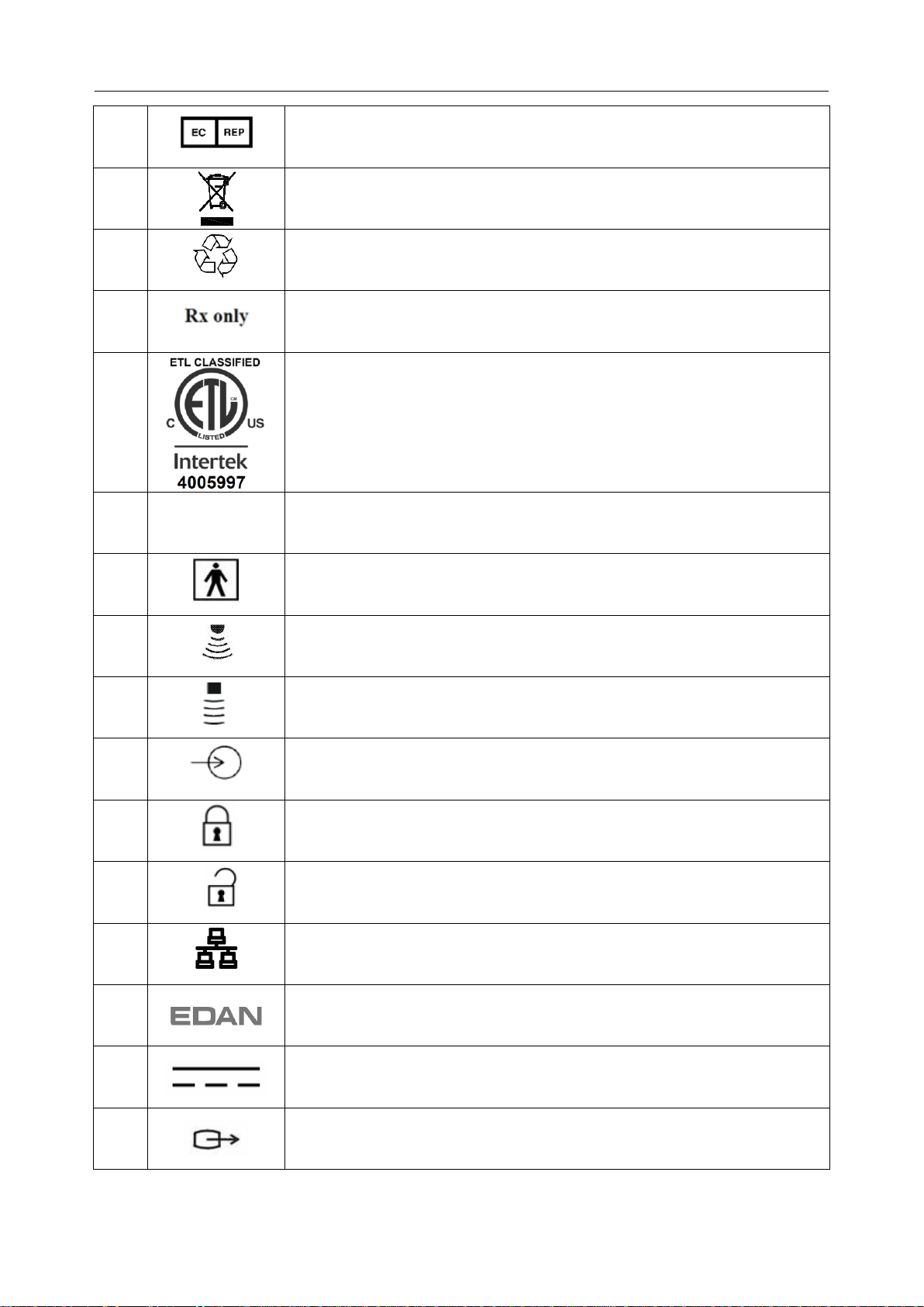
11
Authorized Representative in the European Community
12
Disposal method. Indicates that the equipment should be sent to special
agencies according to local regulations for separate collection after its
useful life.
13
General Symbol for Recovery / Recyclable
14
Caution: Federal (U.S.) law restricts this device to sale by or on the order
of a physician.
15
Conforms to AAMI Std. ES 60601-1, IEC Std. 60601-2-37
Certified to CSA Std. No. 60601-1, No 60601-2-37
16
IPX7
No harm for short time immersion
17
Type BF Applied Part
18
Transducer connector
19
Pencil Transducer connector (reserved)
20
ECG signal input connector (reserved)
21
Transducer lock
22
Transducer unlock
23
Network port
24
Trademark
25
Direct current
26
Video Output port
- 3 -
Page 9
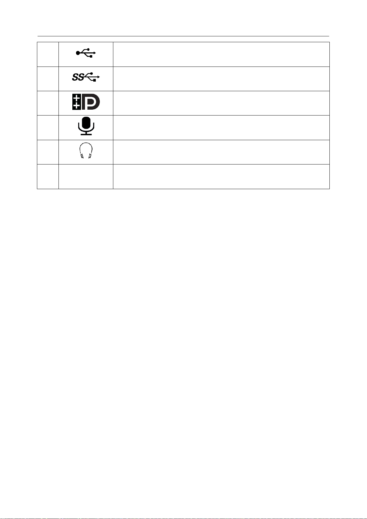
Acclarix AX8 Diagnostic Ultrasound System User Manual Introduction
27
USB 2.0 port
28
USB 3.0 port
29
Display port
30
Microphone input
31
Headphones
32
FCC ID:
SMQAX8EDAN
Federal Communication Commission: FCC ID: SMQAX8EDAN
NOTE:
The user manual is printed in black and white.
- 4 -
Page 10

Acclarix AX8 Diagnostic Ultrasound System User Manual Safety
2 Safety
Throughout this document the following terms are used:
Warning: Advises against certain actions or situations that could result in personal injury
or death.
Caution: Advises against actions or situations that could damage equipment, produce
inaccurate data, or invalidate a procedure.
Note: Provides useful information regarding a function or a procedure.
Please read all warnings and cautions prior to using the Acclarix AX8 ultrasound system. For
your convenience all warnings and cautions are provided in this section. These may be duplicated
elsewhere in this document in the context of the instructions for use.
2.1 Warnings
Only use an Edan supplied power adapter and power cord.
Only use an Edan supplied battery. Read and understand the battery installation
instructions prior to changing the battery.
Only use Edan supplied transducer. Use of other transducers may result in electric
shock or system malfunction.
Only use a hospital grade, grounded, power outlet and plug. Do not use with an
ungrounded outlet.
The system is ordinary equipment (Sealed equipment without liquid proof). But the
console panel including touch screen, track pad and hard keys is IPX1.
Transducer (not including the transducer connector) is IPX7. Footswitch is IP68.
Do not immerse or expose any of the parts to extended moisture. Splash
resistance does not extend to transducer connectors. Keep connectors dry.
Do not use in a wet environment or when the relative humidity exceeds 95%.
Do not reverse the positive and negative poles when installing a battery.
Do not use the battery near heat sources or when the ambient temperature is over
40oC. Do not heat or dispose of in fire.
Do not destroy the battery; do not pierce or cause a strong impact to the battery.
Do not touch the connector pins on the transducer port.
Parts and accessories used must meet the requirements of the applicable
IEC/EN60601 series safety standards, and/or the system configuration must meet
the requirements of the IEC/EN60601-1.
Use protective barriers (gloves and transducer sheaths) whenever possible.
Follow sterile procedures when appropriate. Thoroughly clean Transducers and
reusable accessories after each patient examination and disinfect or sterilize as
needed. Refer to transducer use and care instructions. Follow all infection control
policies established by your office, department or institution as they apply to
personnel and equipment.
- 5 -
Page 11

Acclarix AX8 Diagnostic Ultrasound System User Manual Safety
Not intended for Ophthalmic use.
If a sterile transducer cover becomes compromised during an intra-operative
application involving a patient with transmissible spongiform encephalopathy, such
as Creutzfeldt-Jakob disease, follow the guidelines of the U.S. Disease Control
Center and this document from the World Health Organization:
WHO/CDS/APH/2000/3, WHO Infection Control Guidelines for Transmissible
Spongiform Encephalopathies. The transducers for your system cannot be
decontaminated using a heat process.
Contact with natural rubber latex may lead to a severe anaphylactic reaction in
persons sensitive to the natural latex protein, Sensitive users and patients must
avoid contact with these items. EDAN strongly recommends that health-care
professionals identify their latex-sensitive patients, and refer to the March 29, 1991
Medical Alert on Latex products. Be prepared to treat allergic reactions
immediately.
Improper operation may cause the internal lithium battery (hereinafter called
battery) to be hot, ignited or exploded, and it may lead to the decrease of the
battery capacity. It is necessary to read the user manual carefully and pay more
attention to warning messages.
Do not touch accessible contacts of electrical equipment and the patient
simultaneously.
This device is not suitable for intra-cardiac use or direct cardiac contact.
The system shall not be serviced or maintained while in use with a patient.
Install the system according the EMC guidance provided in Chapter 14
Do not stack the system on other electronic equipment.
The use of transducer and connecting cable not supplied by the manufacturer may
result in increased emissions or decreased immunity of the equipment.
Refer to Chapter 14 for recommended separation distances from other equipment,
including portable and RF communication devices.
The power adapter is used to isolate the system from main power. Position the
system so that it is easy to disconnect the device.
No modification of this equipment is allowed.
The system should be maintained regularly, at least annually, by a qualified
technician who has adequate training, knowledge and experience. That person
should be familiar with the AX8 Service Manual (P/N: 01.54.002483), available
from your Edan representative.
Keep non-medical equipment (such as the external printer) out of the vicinity of the
patient. (1.5m/6ft.)
Use of an extension cord or multi-socket outlet setup to provide power to the
ultrasound system or to the system‟s peripheral devices, may compromise the
- 6 -
Page 12

Acclarix AX8 Diagnostic Ultrasound System User Manual Safety
system grounding and cause the system to exceed leakage current limits.
SHOCK HAZARD – Do not connect non-isolated electrical equipment to the same
circuit being used to power the system.
Edan recommends the use of isolated connectors on any electrical equipment
attached to the system, and/or using isolation transformers that complies with
IEC60601-1 to power that electrical equipment.
Always use sterile technique during a biopsy procedure. Sterilize the needle
guide assembly between uses.
Use a sterile needle with each use.
Always confirm the clinical accuracy of the IMT result before entering it into the
report.
Transducer Warnings
To avoid infection, always use protective gloves when cleaning or disinfecting
Read and follow all manufacturer instructions for disinfection agents.
To avoid infection, ensure that expiration date of the disinfecting solution has not
passed.
Disinfect the transducer after each intra-cavity or intra-operative procedure. Use a
new sterile sheath for each such procedure.
Use a pyrogen-free transducer sheath for neurological intra-operative procedures.
Unplug the transducer from the system prior to cleaning or disinfecting.
Do not immerse the transducer beyond the point indicated in Figure 6-2.
Do not allow the transducer connector to get wet.
2.2 Cautions
The system contains no user serviceable components other than the battery. Do
not remove any covers.
Excessive dust and dirt could clog internal airflow and cause overheating. Do not
use in a dusty environment.
Do not use a battery that leaks, emits an odor, appears deformed, or discolored.
Immediately replace it with a new Edan-supplied battery and dispose of the old
battery according to local regulations. Replace a battery that has reached the end
of its service life.
Use care when storing or disposing of batteries. Do not allow the leakage to come
in contact with each other. Do not dispose of them together with household
garbage. At the end of their life hand the batteries over to the applicable collection
points for the recycling of waste batteries.
Inspect the system regularly, at least weekly. Before use ensure there is no visible
- 7 -
Page 13

Acclarix AX8 Diagnostic Ultrasound System User Manual Safety
evidence of damage to the equipment, cables, and transducers. If a component is
damaged replace it before use.
Do not use in locations subject to vibration.
Read and understand the section A1.2 Ultrasound Safety and the ALARA Principle
of Acclarix AX8 Advanced User Manual before using the system. Do not expose a
patient to ultrasound energy longer than clinically reasonable.
Practice ALARA principle when operating ultrasound system. Minimize the
acoustic power without compromising the image quality.
Do not use in the presence of a flammable anesthetic.
The system generates radio frequency energy, which may cause interference with
other devices in the vicinity. If interference is suspected, try re-orienting or
relocating the equipment.
The use of electrosurgical units or other devices that generate radio frequency
interference may cause image distortion or other malfunction.
During long term storage the battery should be charged at least once every 3
months to ensure battery capacity.
The system should only be used by a qualified physician or allied health
professional for ultrasound evaluations.
Use only Edan supplied or recommended parts and accessories.
Verify measurement results prior to entering them into a report.
Contact your local distributor or Edan service if there is excessive noise from the
system speaker or fans.
Please read and understand cleaning instructions prior to use.
Please read and understand maintenance instructions prior to use.
Please read and understand instructions for system operation prior to use.
Studies stored on the system hard drive should be archived regularly. The system
is not intended for long term storage of patient information. Confirm successful
archiving before deleting a study from the hard drive.
Ensure that the system vents are clear and unobstructed.
Confirm patient identification information prior to storing or printing any exam
information.
If you have any questions about maintenance, technical specifications, or system
functionality, please contact your local distributor or Edan service at:
support@edan.com.cn
Ultrasound images occasionally have artifacts, and should only be used as one
part of an overall clinical assessment.
To avoid electrical shock, turn off and disconnect the device from the AC power
- 8 -
Page 14

Acclarix AX8 Diagnostic Ultrasound System User Manual Safety
source before cleaning and disinfecting.
The device and accessories are to be disposed of according to local regulations
after their useful lives. Alternatively, they can be returned to the dealer or the
manufacturer for recycling or proper disposal.
Transducer Cautions
Do not use disinfection agents beyond their expiration date.
Do not use sterile sheaths beyond their expiration date.
Inspect the transducer connector, cable, and head periodically. Do not use if there
is evidence of excessive wear or damage.
Do not operate the transducer to temperatures in excess of 40°C or storage the
transducer to temperatures in excess of 55°C .
Do not kink or pull on the transducer cable.
Broken or bent connector pins can cause image artifacts. Do not use a transducer
with broken or bent pins.
- 9 -
Page 15

Acclarix AX8 Diagnostic Ultrasound System User Manual Getting Started
Printer Model
Printer Type
Interface
SONY UP-25MD
Color Image
S-Video
SONY UP-D25MD
Color Image
USB
SONY UP-X898MD
B/W Image
USB
HP Officejet Pro 251dw
Color Report
USB
HP Laserjet Pro 200 M251n
Color Report
USB
HP Laserjet CP1525n Color
Color Report
USB
HP Deskjet Ink Advantage 2010
Color Report
USB
HP Deskjet 1010 Color
Color Report
USB
HP Deskjet 1510 Color
Color Report
USB
HP LaserJet 400 M401d
B/W Report
USB
3 Getting Started
3.1 System Configuration
The Acclarix AX8 system is shipped with the following components:
Acclarix AX8 main unit
1 rechargeable lithium battery
1 UPS battery
1 AC adapter
1 bottle of coupling gel
1 basic user manual and 1 advanced user manual
The following options are also available (please see the Order List Appendix for details)
Transducers: C5-2XQ, C5-2Q, L10-4Q, L12-5Q, L17-7HQ, E8-4Q, MC8-4Q, P5-1XQ,
L17-7SQ, C5-2MQ*
1 Trolley MT-807
Footswitch
Suitcase
The Acclarix AX8 supports the following external DVD drives: SAMSUNG SE-218GN,
SAMSUNG SE-208GN, LENOVO DB75, ASUS SDRW-08D2S-U and PIONEER
DVR-XU01C.
The Acclarix AX8 supports the following DVD disks: Philips CD-R 700MB 80min 52x,
Sony CD-RW 700MB 1x-4x,Sony DVD-RW 4.7GB 120min 2x/1x,
Verbatim DVD+RW 4.7GB 120min 4x.
Note: Only support DVD disk single burning.
The Acclarix AX8 supports the following printers. Please contact the manufacturer for
details.
Table 3-1 Printer List
- 10 -
Page 16
Acclarix AX8 Diagnostic Ultrasound System User Manual Getting Started
Model
Name
Description
BGK-C5-2
BGK-C5-2 Needle Guide Bracket Kit
For use with the C5-2XQ/C5-2Q,
Supports: 16G, 18G, 20G, 22G
BGK-L40UB
L40UB Needle Guide Bracket Kit
For use with the L10-4Q,
Supports: 16G, 18G, 20G, 22G
BGK-CR10UA
CR10UA Needle Guide Bracket Kit
For use with the E8-4Q,
Supports: 16G
BGK-R15UB
R15UB Needle Guide Bracket Kit
For use with the MC8-4Q,
Supports: 16G, 18G, 20G, 22G
BGK-P5-1X
BGK-P5-1X Needle Guide Bracket Kit
For use with the P5-1XQ
Supports: 14G-22G
1
2
3
4
5
6
7
8
9
Note: For more printer models, please see:
http://hplipopensource.com/hplip-web/supported_devices/combined.html . Generally,
printer models with driver version 3.14.3 or lower can be supported by Acclarix AX8, but
some models cannot be perfectly supported.
Needle Guide Bracket Kit
Table 3-2 Needle Guide Bracket Kits
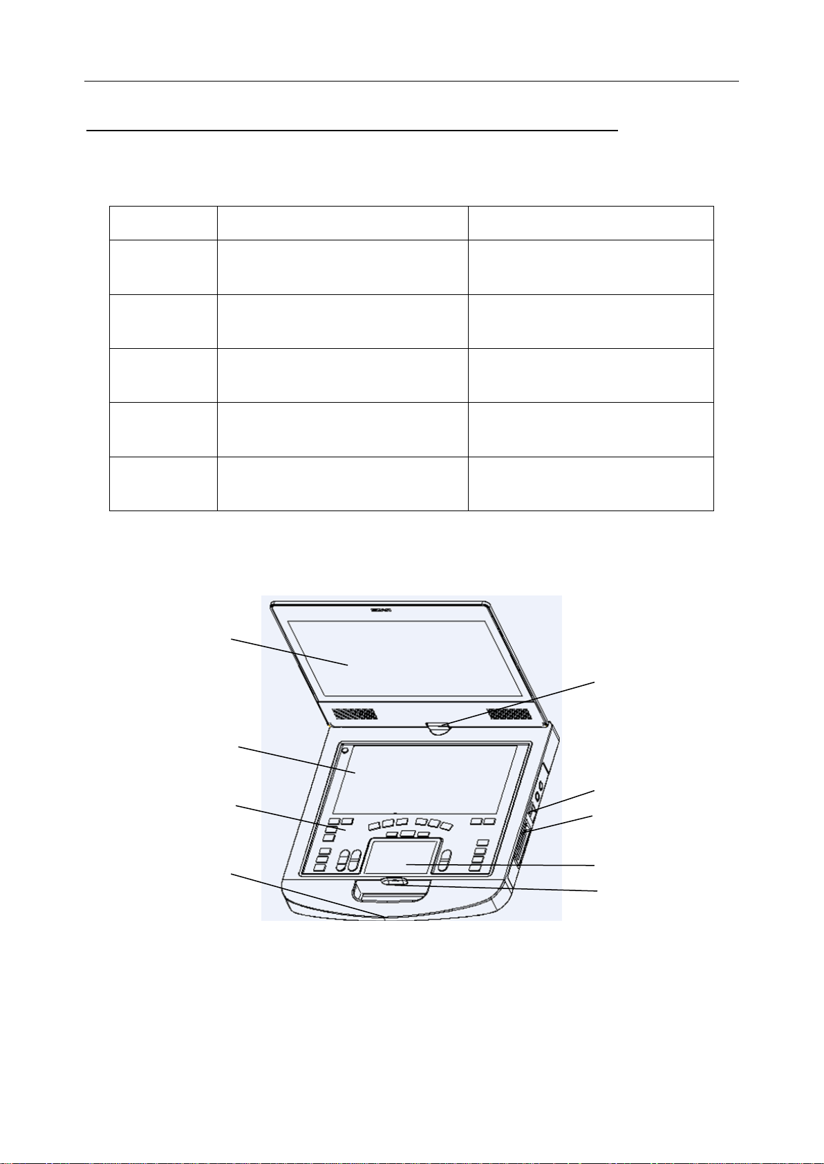
3.2 System Overview
- 11 -
Page 17
Acclarix AX8 Diagnostic Ultrasound System User Manual Getting Started
No.
Name
Description
1
Monitor
Display the images and parameters during
scanning.
2
Touch Screen
Use to control operation and activate functions
3
Control panel
Use to control the operation
4
Handle
Used for carrying the system
5
Hinge
Used to rotate the monitor
6
Transducer locking lever
Use to lock or unlock the transducer
7
Transducer Port
Used for connecting a transducer to the Acclarix
AX8 main unit
8
TrackPad
Use to change the cursor position
9
Battery Indicator
LEDs indicate battery charge. Each LED
corresponds to 20% of battery power. The LEDs
will flicker while the battery is charging. Touch the
battery indicator to view the battery power.
10
I/O Ports
Use to connect the I/O extend modules
10
Figure 3-1 Appearance of the System
Table 3-3 Appearance of the System
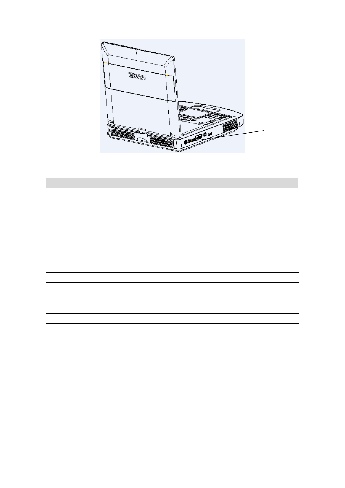
- 12 -
Page 18
Acclarix AX8 Diagnostic Ultrasound System User Manual Getting Started
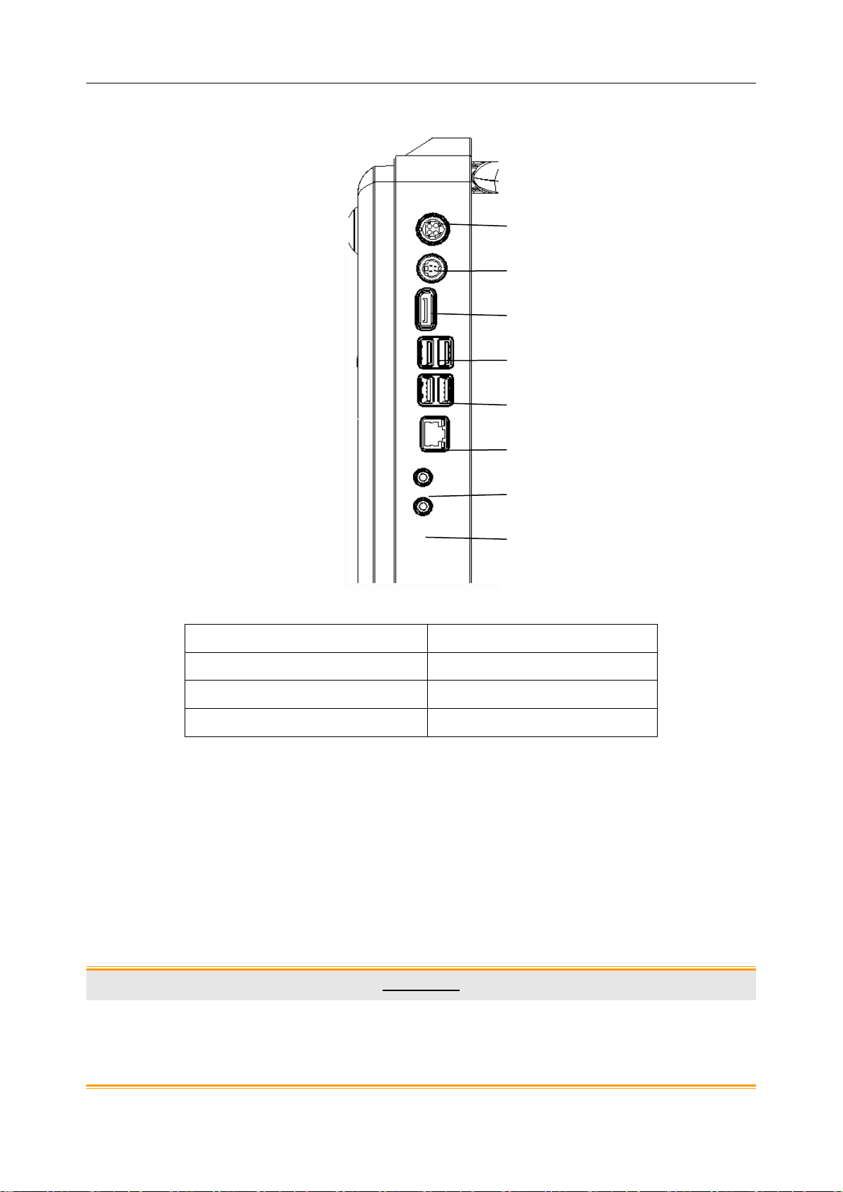
1. Power supply
5. USB 2.0 port
2. S-Video output port
6. Network port
3. Display port
7. Microphone input port
4. USB 3.0 port
8. Audio output port
1 3 4
5 6 7 2 8
I/O Ports on the left panel:
Figure 3-2 I/O ports of the system
Table 3-4 I/O Ports of the System
NOTE:If an external monitor is connected to the system via display port, configure the
resolution to 1920x1080, other resolution may cause abnormal ultrasound machine
display.
3.3 Battery Use
The Acclarix AX8 system comes with one lithium-ion battery. When it is fully charged it can run
the system for approximately 60 minutes, depending on use. It is automatically charged when the
system is plugged in.
CAUTION
1. If the system will remain unused for more than one week, charge the battery to at
least 75%capacity, take the battery out and store the system and battery separately.
2. During long term storage the battery should be charged at least once every 3 months
to ensure battery capacity is more than 75%.
- 13 -
Page 19
Acclarix AX8 Diagnostic Ultrasound System User Manual Getting Started
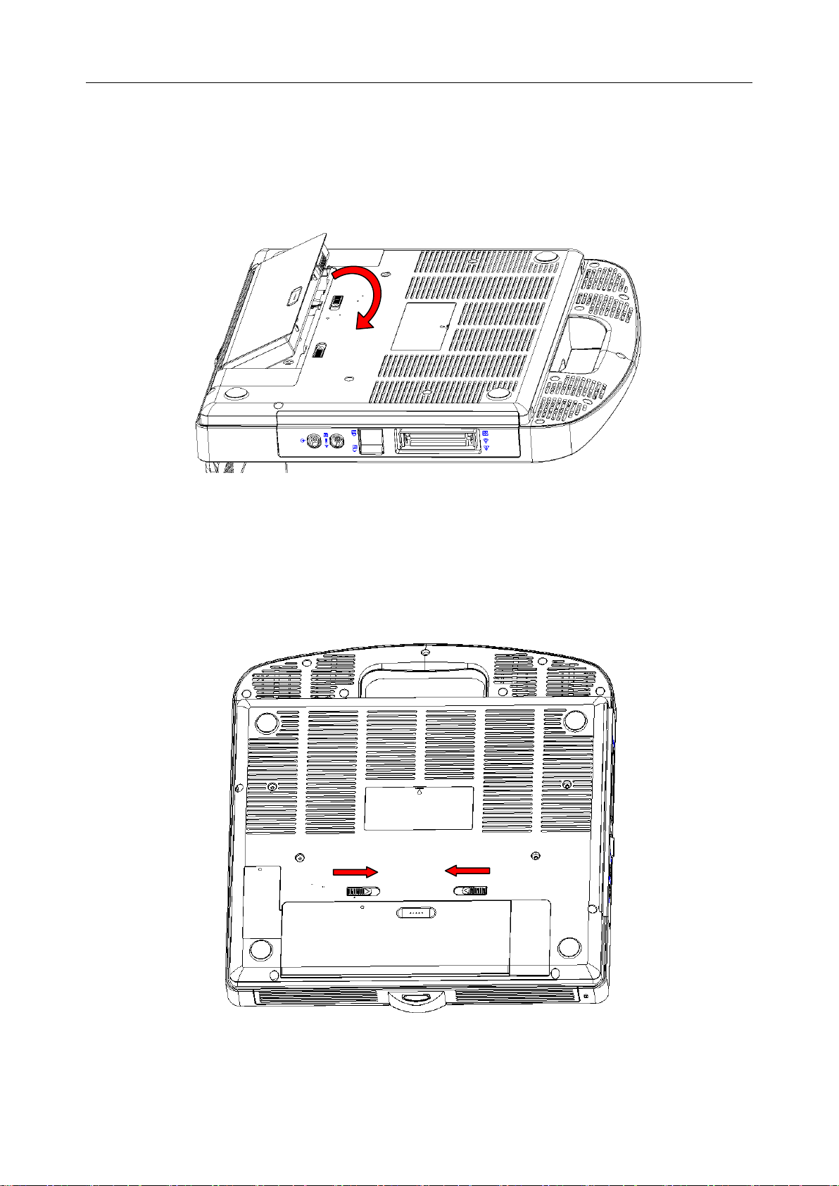
To install the battery:
1. Turn off and unplug the Acclarix AX8 system.
2. Close the monitor, turn the system upside down and rest it on a flat stable surface.
3. Put the battery gently to battery compartment, and the button will lock the battery
automatically.
Figure 3-3 Installation of the Battery
To remove a battery:
1. Turn off and unplug the Acclarix AX8 system.
2. Close the monitor, turn the system upside down and rest it on a flat stable surface.
3. Slide the battery button to unlock the battery.
4. Take the battery out.
Figure 3-4 Battery Removal
To install the UPS battery:
1. Close the monitor, turn the system upside down and rest it on a flat surface.
- 14 -
Page 20
Acclarix AX8 Diagnostic Ultrasound System User Manual Getting Started
2. Take out the UPS battery from the package.
3. Put the UPS battery gently to the UPS battery compartment.
Figure 3-5 Installation of the UPS Battery
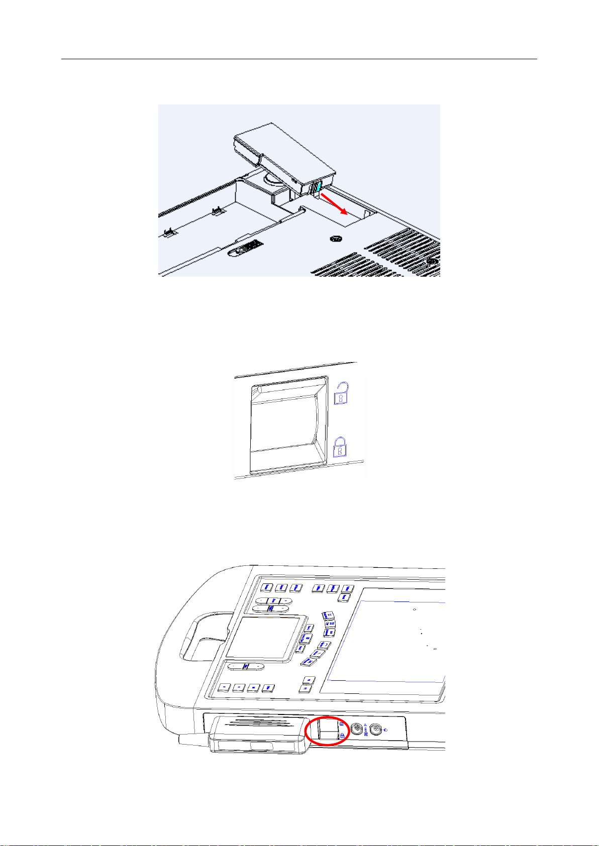
3.4 Connecting and Disconnecting a Transducer
To connect a transducer:
Figure 3-6 Tansducer Locking Handle
1. Align the connector with the transducer port and carefully push into place.
2. Toggle the locking handle to the bottom position.
3. Do not allow the transducer head to hang free. Impact to the transducer head could result in
irreparable damage.
Figure 3-7 Lock the tansducer locking handle
- 15 -
Page 21
Acclarix AX8 Diagnostic Ultrasound System User Manual Getting Started
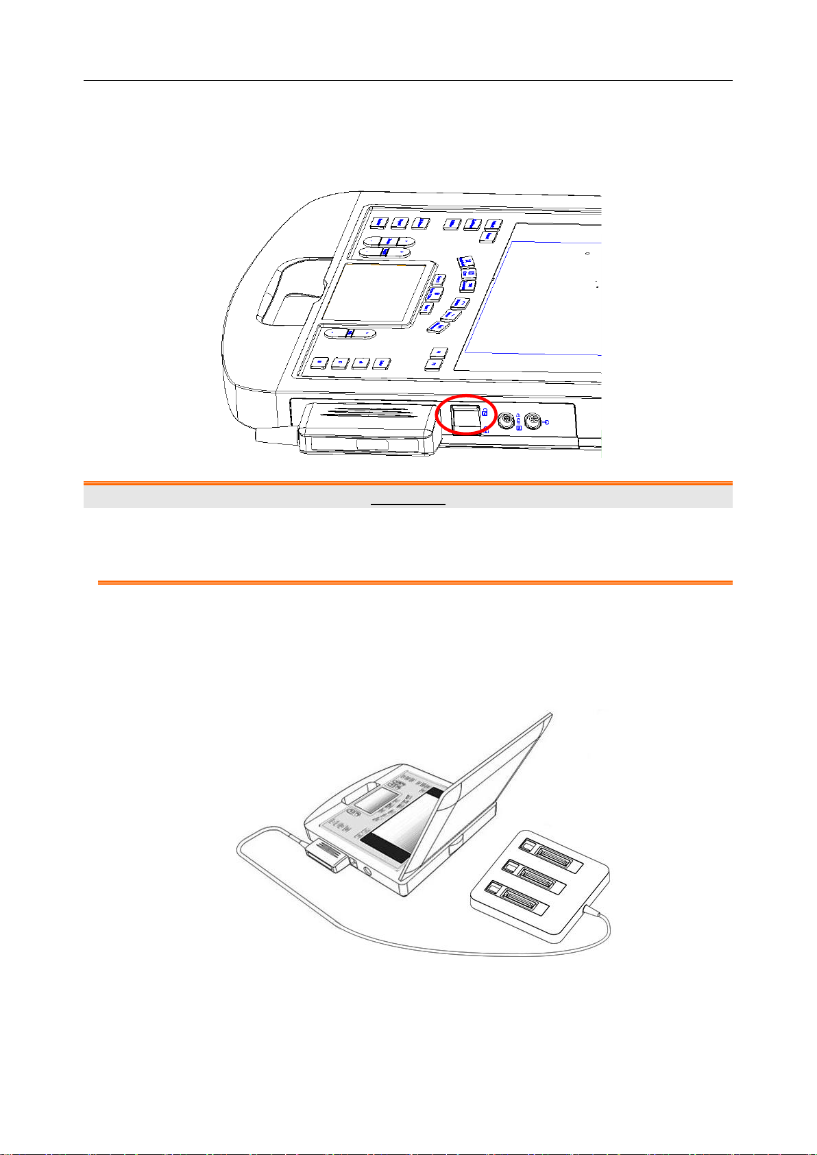
To disconnect a transducer:
1. Toggle the locking handle to the top position to unlock the connection of the Transducer.
2. Firmly grasp the transducer connector and carefully remove it from the system port.
3. Store transducer in its protective carrying case prior to transport.
Figure 3-8 Unlock the Tansducer Locking Handle
CAUTION
1. Do not touch the pins of the transducer connector.
2. Broken or bent connector pins can cause image artifacts. Do not use a transducer
with broken or bent pins.
Multi-Transducer Connector (MTC)
The Multi-Transducer Connector (MTC) is an optional addition to the AX8 that allows up to
three transducers to be connected to the system. The MTC can be mounted to the optional AX8
cart, or lie flat on an adjacent table.
Figure 3-9 Connect to the MTC
Note:
Pluging and unpluging the MTC should be done while the system is frozen or turned
off.
- 16 -
Page 22
Acclarix AX8 Diagnostic Ultrasound System User Manual Getting Started
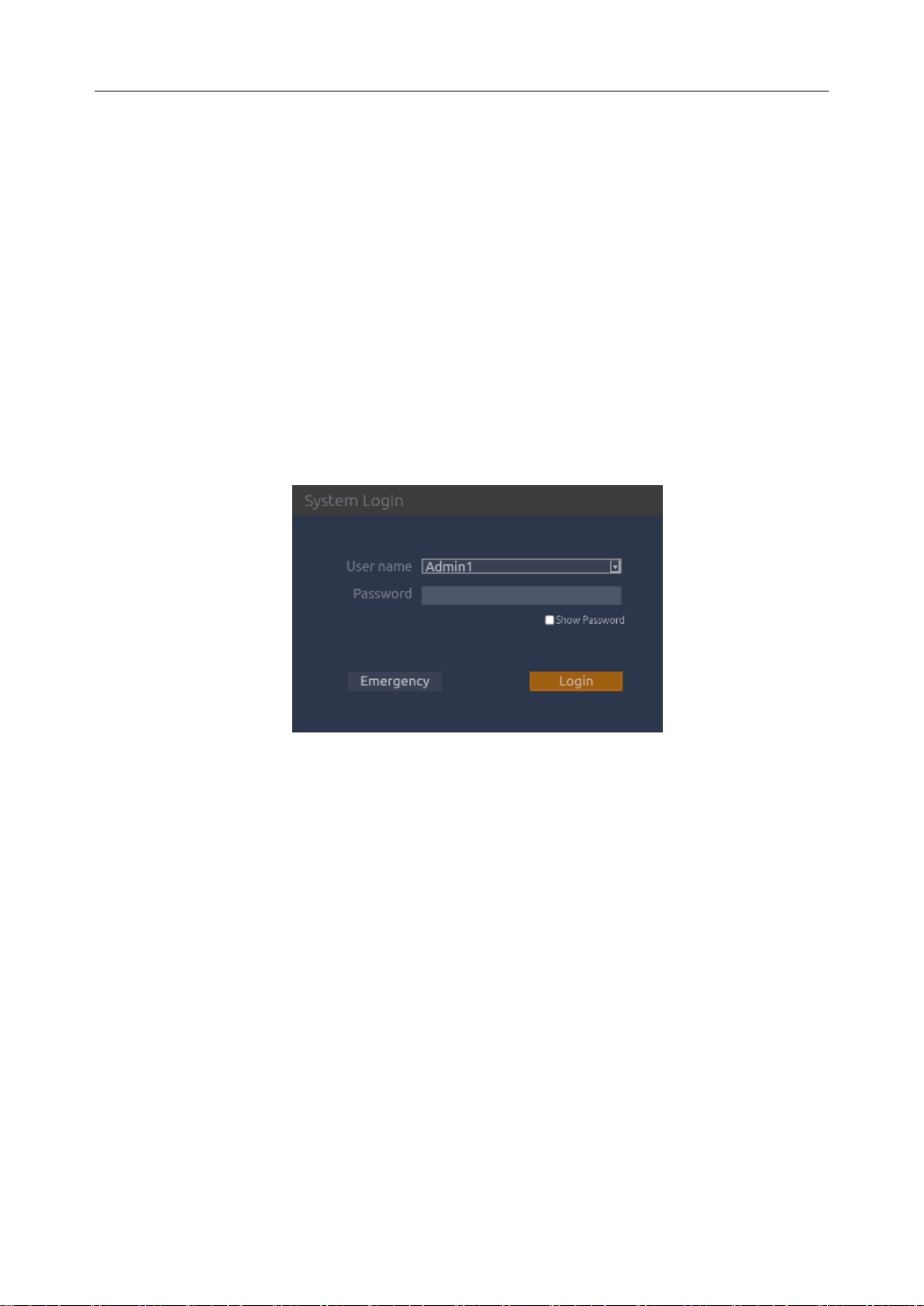
3.5 Powering on/ off
Please review and follow the steps described in the Section 12.1.Daily Checklist prior to
powering on the device.
To power on:
1. Connect the system to a hospital grade power supply, or use the battery as the power supply.
2. Press the power on/off key on the top left of control panel.
To Login
If Password Protection is enabled (see section 9.1.5), the system displays a Login dialog
when booting up the system, you can type in or select user name in the drop-down list of
User name, then enter password and click Login.
For emergency use, you can click on Emergency to log on directly without entering user
name and password.
Note:
When both Admin1 and Admin2 password are forgotten, please contact the
serviceman for the system password reset.
To power off:
1. Press the power on/off key on the top left of control panel and the system displays a
confirmation dialog box.
2. Select “Shut Down” from the confirmation dialog box.
If the system is unresponsive, a long press of the power on/off key will shut down the system
directly.
NOTE:
Please unplug the AC adapter from the power socket and disconnect the battery prior to
storage.
Sleep mode
The system will enter a sleep mode that maintains exam information while using minimal battery.
There are three events that can invoke sleep mode:
- 17 -
Page 23
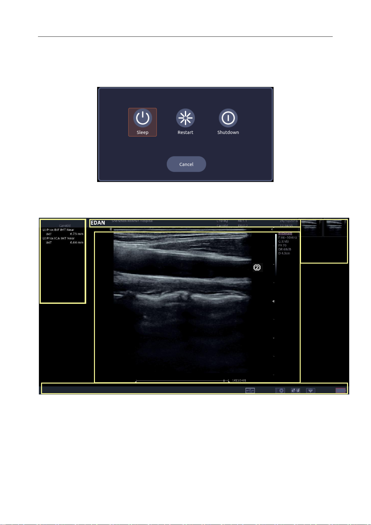
Acclarix AX8 Diagnostic Ultrasound System User Manual Getting Started
①
③
④
⑤
Close the cover of the system without powering-off the system.
No user input for a configurable amount of time. Please see System Set-up to configure
this time.
Pressing the Sleep button on the confirmation dialog box when powering off.
Figure 3-10 Confirmation Dialog Box When Power off
3.6 Screen Layout
Figure 3-11 Main Screen Display
①Information Field:
The top line of this field contains your hospital/institution name. Please see Section 9.1.
General Set-up for information on customizing this area.
The second line of this field contains the patient name, gender, age and ID, as entered
through the Patient Information screen.
This field also contains data fields for:
The currently active transducer
- 18 -
Page 24
Acclarix AX8 Diagnostic Ultrasound System User Manual Getting Started
The currently active preset
MI, TI, current date and time.
②Image Field:
The ultrasound image appears in the Image Field, under the Information field. The image
field also contains information typically associated with the image, such as scales, TGC, and
maps. The system supports two different image sizes within the image field. See 9.1.1 for
details
③Mini Report:
The left side of the screen displays a “mini-report” which provides a synopsis of applications
measurements performed in the current exam.
④Thumbnail Field:
The right side of the screen displays thumbnail images of all statics and clips captured in the
current exam.
⑤Status Bar:
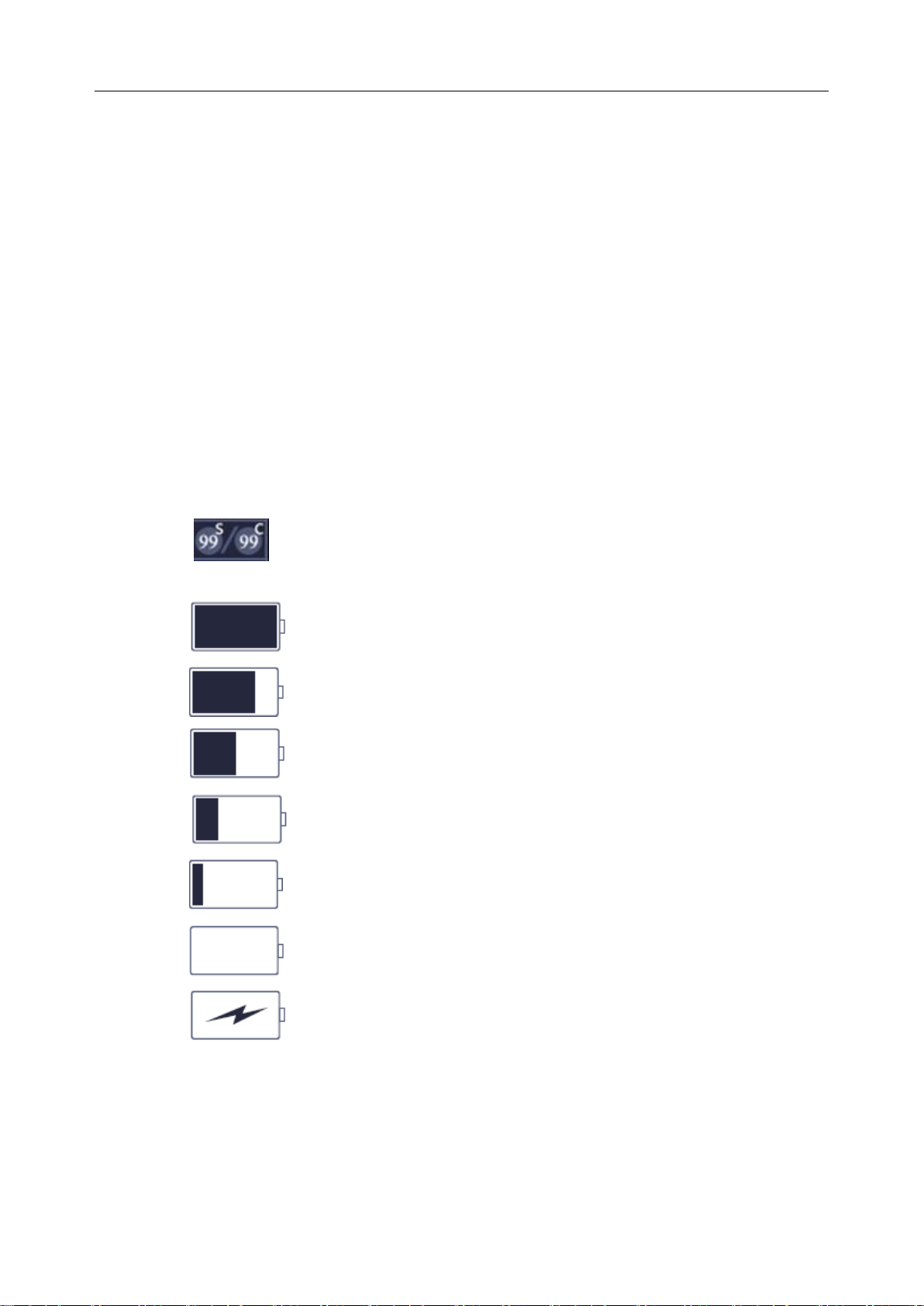
The bottom of the screen is used to display icons that provide system status. These include:
Image Store icon
: Number of static images and clips in the current exam.
Battery icon
: Battery fully charged, symbol in green.
: Battery higher than 80%.
: Battery 60%-80%.
: Battery 40%-60%.
: Battery low, symbol in red.
: Battery removed, outline in red.
: Battery charging.
Network status icon
The network icons show the connection status of the DICOM or FTP Server. If no
Network Server is defined then the icon does not show at all.
- 19 -
Page 25
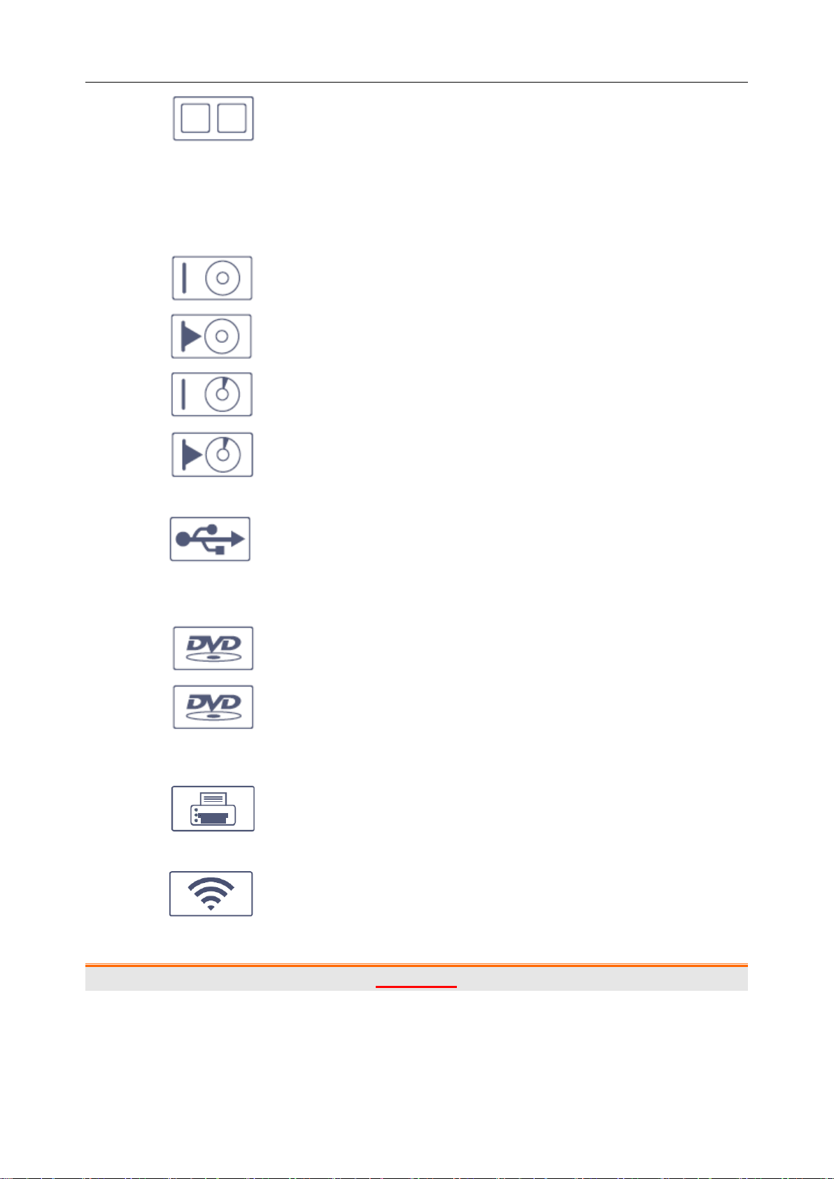
Acclarix AX8 Diagnostic Ultrasound System User Manual Getting Started
:
Outline in grey color: Successful connection with a Server.
Outline in green color: Data exchange with a Server.
Outline in red color: Failure to connect with a configured Server.
Hard drive icon.
: Hard drive available
: Hard drive data exchange, symbol in green.
: Hard drive 95% full, symbol in red.
: Hard drive 95% full with data exchange, symbol in red.
USB icon
:
Symbol in grey color: USB available
DVD icon
: Symbol in grey: DVD device is connected
: Symbol in green: DVD device is connected, disc is inserted and data
transmission is available.
Printer icon
: Printer available.
Wifi icon *
:Wi-Fi available, Subject to regulatory approval. See Connectivity (Section
9.2.1) for enabling wireless if it is licensed. Clicking on this icon shows a list of all Wi-Fi networks that
are currently available.
WARNING
The system complies with Part 15 of the FCC Rules. Operation is subject to the following
two conditions:
1) this device may not cause harmful interference, and
2) this device must accept any interference received, including interference that may
- 20 -
Page 26
Acclarix AX8 Diagnostic Ultrasound System User Manual Getting Started
No.
Key
Name
Description
1.
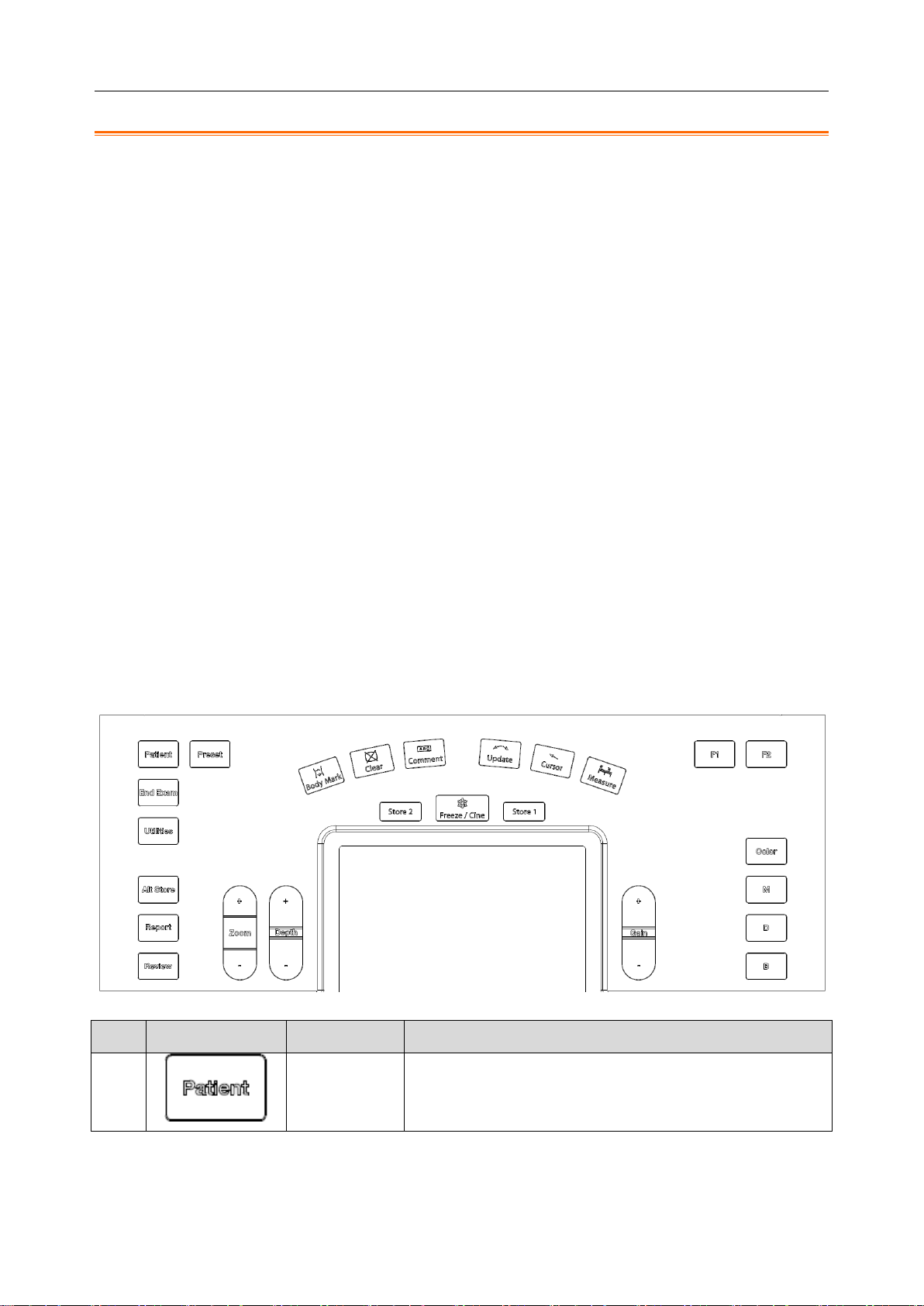
Patient
Invokes the Patient Information Screen. Typically used to
start/end exams or to modify patient information during an
exam. See section 4.1
cause undesired operation.
NOTE:
1. This equipment has been tested and found to comply with the limits for a Class B
digital device, pursuant to part 15 of the FCC Rules. These limits are designed to
provide reasonable protection against harmful interference in a residential installation.
This equipment generates, uses and can radiate radio frequency energy and, if not
installed and used in accordance with the instructions, may cause harmful
interference to radio communications. However, there is no guarantee that
interference will not occur in a particular installation. If this equipment does cause
harmful interference to radio or television reception, which can be determined by
turning the equipment off and on, the user is encouraged to try to correct the
interference by one or more of the following measures:
- Reorient or relocate the receiving antenna.
- Increase the separation between the equipment and receiver.
- Connect the equipment into an outlet on a circuit different from that to which the
receiver is connected.
- Consult the dealer or an experienced radio/TV technician for help.
2. Any changes or modifications to this unit not expressly approved by the party
responsible for compliance could void the user's authority to operate the equipment.
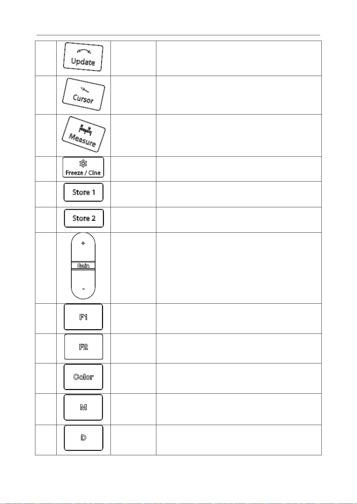
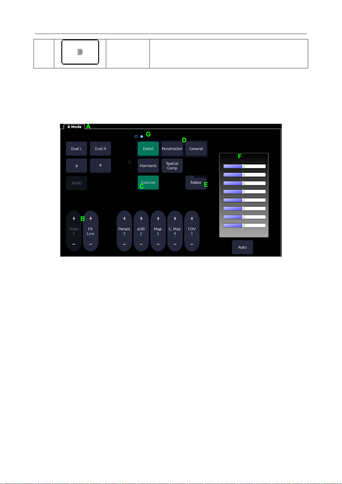
3.7 Control Panel
Figure 3-12 Control Panel of the System
- 21 -
Page 27
Acclarix AX8 Diagnostic Ultrasound System User Manual Getting Started
2.
Preset
Allows you to change the Preset being used. See section
8 for details.
3.
End Exam
Completes an exam without invoking the Patient
Information Screen for the next exam. See section 4.2
4.
Utilities
Press this button to get the Set Up, Maintenance,
Connectivity and Screen Adjust keys on the touch screen.
5.
Alt Store
One of three keys that can be configured to store images
or clips, or to set video printers. See section 7.4 for
details.
6.
Report
Press to display the report page
7.
Review
Press to enter exam database or image review mode. See
section 7.4 for details.
8.
Zoom
Press to zoom the image in or out. See section 5.1.5 for
details.
9.
Depth
Press to adjust the depth of the image displayed.
10.
Body Mark
Enters or exits the Body Mark function. See section 7.2 for
details.
11.
Clear
Press to clear all the measurements, calculations,
comments, and body marks displayed in the current
image.
12.
Comment
Enters or exits the Comment function. See section 7.1 for
details.
- 22 -
Page 28
Acclarix AX8 Diagnostic Ultrasound System User Manual Getting Started
13.
Update
In Strip Doppler this switches between acquiring the
Doppler strip and the reference image. See section 5.2.3
for details.
14.
Cursor
Press to hide or display the cursor
15.
Measure
Invokes the Measure function for Generic and Application
Measurements. See section 7.3 for details.
16.
Freeze/Cine
Press this key to switch between the frozen and real-time
states.
17.
Store 1
One of three keys that can be configured to store or print
images or clips, or to set video printers. See section 7.4
for details.
18.
Store 2
One of three keys that can be configured to store or print
images or clips, or to set video printers. See section 7.4
for details.
19.
Gain
Controls the overall gain for the imaging mode that
currently has the UI focus. In normal imaging the gain can
also be adjusted by sliding your finger along the top of the
trackpad area
20.
F1
User-defined button
21.
F2
User-defined button
22.
Color
Press to enter or exit Color Mode. See section 5.4 for
details
23.
M
Press to enter or exit M Mode. See section 5.5 for details.
Use the trackpad to adjust the M sample line.
24.
D
Press to get the sample line, use the trackpad to adjust
the position and press the hardkey again to confirm.
For other information, see section 5.2 and 5.3 for details.
- 23 -
Page 29
Acclarix AX8 Diagnostic Ultrasound System User Manual Getting Started
25.
B
Press to return to B-mode imaging from any display or
imaging mode. See section 5.1 for details.
Table 3-4 Buttons on Control Panel
3.8 Touch Screen
The Touch Screen contains controls that vary depending on the active function.
There are several types of controls used by the touch screen, as illustrated below:
Figure 3-13 Touch screen of the System
A. Tabs: Each function that is active has a tab on the touch screen. Usually the function that
was most recently activated is the top tab. Pressing on any other tab will bring it to the top
and provide access to that function‟s controls.
B. Slider: Pressing on the top or bottom of a slider changes the control setting by one value.
Pressing anywhere on the control and dragging will continuously change the value.
C. Push button: This can either be an on/off control (like “Colorize”) or a one-shot control
that immediately performs an action (like “Auto”)
D. Radio Buttons: A collection of buttons where only one is active at any time. Activating
one will de-activate all others.
E. Folder: Controls can be grouped together into a folder. Pressing on the folder will open it
to access any of the controls in it.
F. TGC: The B-mode tab has a specialized control for TGC. Each slider can be dragged
horizontally and individually. Dragging vertically down across the sliders will set all
sliders.
G. Pages: When a tab has multiple pages of controls each page is represented by a dot at the
top of the page. The current page is indicated by a filled-in dot. You can move between
pages by dragging your finger horizontally across the dots. These dots do not appear when
there is only one page in the current tab.
- 24 -
Page 30

Acclarix AX8 Diagnostic Ultrasound System User Manual Getting Started
Customizing the touch screen
The touch screen can be customized to meet your needs. Press and hold any control for about a
second to put the touch screen in customization mode. Continue pressing and drag the control to a
new location.
Creating Folders: Dragging one control on top of another control will create a folder that
contains both controls. Dragging controls out of a folder until only one exists will
automatically delete that folder. Folders cannot contain other folders.
Multiple pages: Dragging a control to the side of the screen will move that control to the
next page.
Radio Button Cluster: There is no restriction on moving a single radio button. However,
we suggest that they are grouped adjacent to each other. When they are grouped in this
way the system will automatically draw a border around them to indicate they are a
related group of radio buttons.
TGC: The TGC is a special control that cannot be moved. It is always on the right side of
the B-mode tab.
For most tabs there is one arrangement of controls. Whatever way they are customized will be
remembered across exams and across power-ups. However, the following tabs can have multiple
different arrangements:
Comments
Bodymarkers
Measurements
These functions are often configured differently for different exams. For example, the
measurements for an OB exam are different from those of an abdomen exam. Each configuration
of these tabs is stored in an application preset (see Chapter 8 Presets, for details)
3.9 Trackpad
In general the Acclarix AX8 trackpad is used like a trackball or similar pointing device used on
most ultrasound systems. Using a trackpad instead of a trackball helps make the console sealed,
and makes the system easier to clean. In addition, there are several capabilities that the trackpad
supports that would not be possible on a traditional trackball:
The trackpad supports multi-finger gestures. For example:
o While in B-mode a pinch-out gesture can be used to zoom the image.
o While in Color a pinch gesture can re-size the ROI.
Dragging along the Swipe button on top edge of the trackpad as a primary sliding control.
For example:
o In most live imaging modes this is Gain.
The top right of the trackpad is reserved as a „Set‟ button. Pressing this corner is generally
equivalent to a single click on a mouse or trackball. For example:
o In CD it is used to toggle between controlling the size and the position of the pan
box.
o In Measure it is used to toggle between controlling one side or the other side of a
caliper pair.
The top left of the trackpad is reserved as an „Enter‟ button. Pressing this corner is
- 25 -
Page 31

Acclarix AX8 Diagnostic Ultrasound System User Manual Getting Started
generally equivalent to a double click on a mouse. For example:
o In Measure it is used to enter a measurement into a report.
The examples provided above are a subset of how the trackpad is used. Additional examples are
provided in specific feature descriptions elsewhere in this manual.
- 26 -
Page 32

Acclarix AX8 Diagnostic Ultrasound System User Manual Exam Operation
4 Exam Operation
4.1 How to Start an Exam
To start a new exam, press the Patient key and enter in patient information for the exam, or select
a scheduled patient from the modality worklist.
If there is no previous exam this will bring you directly to the Patient Information Page (see
figure 4-2 below). If a previous exam is still active you will see the following dialog:
Figure 4-1 Exam Confirmation Dialog
It has the following options:
Edit Current: This lets you edit the Patient Information for the current exam. It does not
start a new exam.
New Exam: Select this to start a new exam with the same patient. It confirms that you
want to end the previous exam, and then displays the Patient Information Page with the
previous patient information still displayed.
Cancel: Exits the dialog without starting or ending an exam.
New Patient: Select this to start a new exam. It confirms that you want to end the
previous exam, and then displays a blank Patient Information Page for the new exam.
4.2 How to End an Exam
There are two ways to end an exam:
Pressing the Patient key, as described above, and then selecting the New Patient. This
both ends the exam and presents the Patient Information Page for the next exam. This is
the most common way of ending the exam, especially when there are several exams in a
row.
Pressing the End Exam key. This brings up a dialog to confirm you want to end the exam,
but does not invoke the Patient Information Page for the next exam. You might end the
exam this way when there is no exam next.
When an exam is ended the associated files on the system are closed. If a DICOM server is
connected successfully and Auto-transfer when End Exam is configured, any remaining images
are transferred.
4.3 How to Restart an Exam
1. Select an exam within the time limit in Exam Database. For the setting of time limit, refer to
section 9.1.2 Patient Set-up.
2. Press Restart on the touch screen to continue/edit the exam that was performed on the
selected patient. You can also modify the patient information by pressing Patient-->Edit
Current.
- 27 -
Page 33

Acclarix AX8 Diagnostic Ultrasound System User Manual Exam Operation
4.4 The Patient Information Page
The Patient Information Page is used to enter or modify patient demographic data. The following
figure is an example:
Figure 4-2 Patient Information Page(OB Exam)
The top three lines are for entering the patient last name, first name, ID, exam accession number,
and DOB (Date-of-Birth) or age. If a date of birth is entered the age is automatically calculated.
Note:
By default the patient name is two fields: family name and given name. It can be
configured to be one field in the Patient Setup screen (See section 9.1.2 for detail).
The next line shows the current transducer, and the preset that will be used for the current exam.
See section 8.3.1.2 for information on presets. The preset can be changed by clicking this
drop-down and selecting one of the other presets associated with the current transducer.
The lines below the preset-selection vary depending on the current preset (see section 8.3.1.2 for
detail). They show clinical information that is preset-specific.
Gender: Select the patient‟s gender: “M” (Male), “F” (Female), “O” (Other), or “<blank>”.
“F” is default for gynecology, obstetric and breast exams; “M” is default for prostate
- 28 -
Page 34

Acclarix AX8 Diagnostic Ultrasound System User Manual Exam Operation
exam and testis exam; <blank> is default for others exam.
LMP: Last Menstrual Period (yyyy/mm/dd), If LMP is entered then GA and EDD are
calculated. Entering EDD does not impact LMP. An LMP more than 300 days ago is
considered invalid.
GA: Gestational Age (xxWyD), it is auto-calculated when LMP or EDD is entered (only
in OB Exam). A GA of more than 42W6D is considered invalid and not displayed.
EDD: Estimated Date of Delivery (yyyy/mm/dd). It is auto-calculated when LMP is
entered..
Fetus: Enter 1 up to 4, for multiple gestations.
G/P/A: G stands for Gravida, P stands for Para and A stands for Aborta. Enter the times of
them in the fields separated by slashes.
Study Description: enter the study description.
Height: Enter the patient‟s height. The units can be set in the Patient section of Setup.
Weight: Enter the patient‟s weight. The units can be set in the Patient section of Setup.
BSA: Body Surface Area, it is auto-calculated and displayed when Height/Weight is
entered.
HR: Enter the Heart Rate.
BP: Enter the Blood Pressure.
PSA: Prostate Specific Antigen.
PPSA Coefficient: Predicted Prostate Specific Antigen.
Ref. Physician: Enter the name of the Ref.Physician.
Dx. Physician: Enter the name of the Dx.Physician.
Operator: Enter the name of the person performing the exam. .
CPT code: Current Procedural Terminology code.
<Custom field 1>: Enter the user-defined data.
<Custom field 2>: Enter the user-defined data.
Comments: Enter any additional comments.
While the Patient Information Page is displayed the following touch screen controls are shown:
- 29 -
Page 35

Acclarix AX8 Diagnostic Ultrasound System User Manual Exam Operation
Figure 4-3 Patient Information Touch Screen
Press Start Exam to exit the Patient Page function and return to B-mode imaging with the newly
entered demographic data entered for the active exam.
Press Cancel to exit the Patient Information Page without storing any of the entered data.
Press Clear All to clear all of the demographic fields except for name and ID.
Input LMP, and press Prior Exam to enable the entry of previous OB exam data for fetal
trending details, it is only available when an OB preset is selected.
4.5 Modality Worklist
Modality worklist provides a list of scheduled patients derived from a DICOM server. It is
available only when a DICOM server is configured and worklist is enabled.
When the modality worklist function is enabled and configured in DICOM Connectivity screen,
the worklist is shown to the left of the Patient Information Page, as shown below.
- 30 -
Page 36

Acclarix AX8 Diagnostic Ultrasound System User Manual Exam Operation
Figure 4-4 Modality Worklist Display
The worklist is displayed at the left side of the Patient Information Page in two columns showing
patient name and patient ID. Clicking on the header of each column will sort the list by the
corresponding column.
The worklist shows all scheduled ultrasound exams within the date-range specified in the
Connectivity Utility (See 9.2.2). Typing any text in the Patient Name or ID fields will filter the
list to exams that contain the entered text.
Update: Press it to query the patient data and update the list manually.
Hide List: Press it to hide the list with only a Show List button displayed. Press the Show List
button to display the list and other buttons.
Select one patient from the list and the detailed patient information is filled in the associated
fields on the patient information page, allowing you edit or complete. Then press Start Exam on
the touch screen to start an exam.
- 31 -
Page 37

Acclarix AX8 Diagnostic Ultrasound System User Manual Imaging
Key
Description
The B-mode key behaves differently than the other mode keys. B-mode imaging is
the baseline state of the system. Therefore, the B key returns to B-mode imaging at
any time from any display on the system. See section 5.1 for B-mode controls.
Invokes and exits strip Doppler mode. Press D button and press PW/CW on the
touch screen to switch to CW mode (requires P5-1XQ transducer). See section
5.2/5.3 for Doppler controls.
Invokes and exits color modes, including Color, Power Doppler Imaging (PDI) and
Directional Power Doppler Imaging (DPDI). The default color mode is determined
by the preset and can be changed while Color is active. See section 5.4 for Color
controls.
Invokes and exits M-mode. See section 5.5 for M-mode controls
Name
Control
Description
TGC
The Time Gain Control (TGC) adjusts the gain of the image at
different depths. Each slider can be adjusted separately, or you can
drag your finger vertically to set all of the sliders to a new setting.
Auto
The Auto push button controls automatically updates the Gain and
TGC. Each single press of the button renews the automatic
optimization.
Dynamic
Range
The Dynamic Range, or log compression, adjusts how echo
intensities are converted to brightness. A high dynamic range
presents a flat image, while a low dynamic range present a large
range of intensities.
5 Imaging
The imaging modes are entered and exited via dedicated hard keys along the right side of the
console.
Table 5-1 Mode Control Hard Buttons
5.1 B-mode
5.1.1. B-mode Touch Screen Controls
The following touch screen controls impact the B-mode image. Touch screen controls can be
located where you want them to be. See section 3.8 for details.
- 32 -
Page 38

Acclarix AX8 Diagnostic Ultrasound System User Manual Imaging
eSRI
eSRI is Speckle Reduction Imaging. There are 4 levels: Off, Low,
Med. and High. High level provides more aggressive speckle
reduction.
Persistence
Persistence averages frames together in order to reduce random
noise. There are 4 options: Low, Med., High and Off. The
persistence level corresponds to the number of frames averaged.
The frame rate is unchanged; as each new frame is acquired it is
averaged with the preceding frames.
Frequency
This determines the fundamental or harmonic (with harmonic
invokes) frequencies used for imaging. It is available on live
images.
Harmonic
The Harmonic control invokes and exits harmonic imaging. While in
harmonic imaging the control is highlighted and „H‟ in the B-mode
frequency field. Depending on the transducer there may be multiple
harmonic frequencies.
Spatial
Compounding
Spatial Compounding combines images fired from multiple angles
in order to reduce speckle, reduce shadow artifacts, and enhance
contrast. Spatial compounding is an on/off control.
Foc. Num
Focus Number adjusts the number of focus positions. As the
number of foci increases the frame rate will decrease, but there will
be more image uniformity across depths.
Foc. Pos.
Focus Position adjusts the depth of the focus or foci. Upward
presses move the focus shallower, regardless of the U/D invert
status of the image.
Gray Map
Gray Map adjusts the post processing map used on the B-mode
image. In general, higher map numbers correspond to more
contrast in the image.
Colorize
The Colorize control adds a color tint to the B-mode image.
Tint
The Tint control changes the color tint being used. Gold, Sepia,
Blue, Ice and Clear are available. If Colorize had been off,
changing the Color map control will automatically activate it.
Left/Right
The Left/Right invert control is indicated by a backward R. It toggles
the left/right orientation of the image. The Edan E orientation
marker at the top of the image switches with the left/right invert to
match the orientation marker on the transducer.
- 33 -
Page 39

Acclarix AX8 Diagnostic Ultrasound System User Manual Imaging
Up/Down
The Up/Down invert control is indicated by an upside-down R. It
toggles the up/down orientation of the image. The TGC also swaps
so the top of the TGC corresponds to the top of the image on the
screen.
FOV
The Field of View control adjusts the image width. Full, Large, Med.
and Small are available. As the image becomes narrower the frame
rate increases.
Steer
This control is only available for linear transducers. It steers the
B-mode image left or right, without moving the transducer. This can
be particularly useful when visualizing needles or other objects that
are enhanced by a perpendicular beam.(in Spatial Compounding,
Trapezoid and Panorama states, steer function is not valid)
Trapezoid
The Trapezoid control activates the trapezoid imaging on linear
transducer. It is a part of the B-mode function and available in live
imaging.
Panorama
The Panorama control invokes the Panorama function. See section
5.1.4 for details.
Image Type
B-mode supports presets for Detail, General, and Penetration. See
section 8.3.1.1 for more information.
Frame rate
Adjusts the tradeoff between frame rate and spatial resolution.
Higher settings provide more temporal resolution.
Dual B
Press to activate dual imaging mode. Dual L activates the live
image on the left side of image field, and Dual R activates the live
image on the right side of image field.
Quad
Press to activate quad imaging mode. Refer to section 5.1.3 Quad
Imaging for details.
3D/4D
Press to activate 3D/4D imaging mode. Refer to section 5.6 3D/4D
mode for details.
Needle
Press to invoke the touch screen menu for Needle Enhancement
Visualization and Needle Biopsy Guide functions. See section 7.5
and 7.6 for more information.
- 34 -
Page 40

Acclarix AX8 Diagnostic Ultrasound System User Manual Imaging
Acoustic
power*
Adjusts the acoustic output power of the activated transducer. It is
only available in live imaging. Higher acoustic power numbers
correspond to more brightness and contrast in the image and more
force of penetration, but the ALARA principle should be followed in
actual situations.
Table 5-2 B-mode Touch Screen Controls
5.1.2. Dual Imaging
Dual Imaging displays images side by side on the screen. During real-time imaging when Dual
imaging is enabled, the active image is displayed in real-time and the other image is frozen.
Press the Dual L or Dual R button on the B-mode touch screen to select the left or right image
for activation. With both images frozen, press the Dual L or Dual R button to toggle between the
images.
Dual Exit
Dual is exited by any of the following:
Pressing the Dual button corresponding to the currently active side.
Pressing the Quad button.
Pressing the B, M, D hard key.
Pressing the 3D/4D button.
Transducer change, preset recall, or new exam.
Color Doppler is available during dual imaging.
5.1.3. Quad Imaging
Quad Imaging displays images in four quadrants on the screen. During real-time imaging when
Quad imaging is enabled, the active image is displayed in real-time and other images are frozen.
Quad imaging is invoked by pressing Quad button on the B-mode touch screen. Quad button is a
one-shot button. Each single press on it during real-time imaging activates one of the four images
in an order from the top left one to the top right one, then to the bottom left one and to the bottom
right one. Each single press on it during frozen status switches among the four images in an order
described above but does not change the frozen status of the system.
Quad Exit
Quad is exited by any of the following:
Pressing the B, M, D hard key.
Pressing the Dual button
Pressing the 3D/4D button
Transducer change, preset recall, or new exam.
Color Doppler is available during Quad imaging.
5.1.4. Panorama
Panorama constructs an extended field of view image as the transducer slides along its long axis.
- 35 -
Page 41

Acclarix AX8 Diagnostic Ultrasound System User Manual Imaging
Panorama is available in live B-mode imaging. To acquire a panoramic image:
Press the Panorama button on the B-mode touch screen.
Press the Set button on the trackpad to start acquisition.
Slide the transducer along the long axis
The B-mode image will extend to incorporate the newly imaged anatomy.
When the full anatomy has been acquired, press the Enter button on the trackpad or press
the Freeze hard key. System also will enter the panorama review state when exceeding the
default time.
After acquisition the completed Panoramic image is redisplayed to fit on the screen.
Measurements*, Comments and Bodymarkers are then supported.
Note:
1. If a measurement function in panorama mode is activated, the caution information of
“The accuracy of measurements in Panorama is limited and can be lower than
measurements in B-image” in yellow font color appears on the bottom of the image
and a caution symbol appears on the head of the measurement results.
2. IMT measurement is not available on panorama image.
Panorama is available only with linear transducers.
Speed Indicator
During an acquisition, a speed indicator bar on the screen will show the current scan speed. Keep
the indicator in the green center of the graphic in order to achieve best results.
Most acceptable normal speed too slow too fast
Figure 5-1 Panorama Speed Indicator
5.1.5. Zoom
Zoom is available in live or frozen B-mode and Color imaging. Press the Zoom hard key to zoom
an image. There are 2 ways to zoom an image: The Zoom paddle key or a pinch-out gesture on
the track pad.
Zoom Paddle key
o Press the upper part of the Zoom paddle to make the image bigger.
o Press the lower part of the Zoom paddle to make the image smaller, down to normal
size.
Pinch Gesture: Use two fingers on the main part of the trackpad, and move the two fingers
outward from each other (“Pinch-out”). The image will enlarge.
When in Zoom mode, use the trackpad to pan the position of zoomed image. The B image
remains zoomed after entering other imaging modes.
- 36 -
Page 42

Acclarix AX8 Diagnostic Ultrasound System User Manual Imaging
Name
Control
Description
Scale
Scale adjusts the range of velocities that are displayed. Upward
presses increase scale and downward presses decrease it.
Increasing scale when the PW cursor is relatively deep may
result in invoking HPRF, if it is configured. See section 5.2.2 for
details.
Baseline
The Baseline control adjusts the Doppler baseline. Upward
presses move the baseline up on the screen and downward
presses move the baseline down.
Invert
Normally signals above the baseline are positive velocities
(moving toward the transducers). However, when Invert is
pressed then negative velocities are above the baseline. Invert
does not affect the baseline position.
Angle
Correct
Adjust the Doppler scale to account for the angle between the
Doppler cursor and the blood flow. Upward presses increment
the angle. Downward presses decrement the angle. Angles
above 80 are not allowed.
Quick-Angle
Adjusts the angle correct quickly to one of 60/0/-60.
Filter
The Filter control removes excessive noise from movement of
vessel walls. Options of Low, Med. and High are available.
Colorize
Switches between grayscale and colorized (pseudo-color)
postprocessing maps.
Gray Map
Tint
Adjusts the current postprocessing, either grayscale or tinted
Dynamic
Range
The Dynamic Range, or log compression, adjusts how signal
intensities are converted to brightness. A high dynamic range
presents a flat spectrum, while a low dynamic range presents a
large range of spectrum brightness.
5.2 PW-mode
5.2.1. PW Touch Screen Controls
The following touch screen controls impact the PW image. Touch screen controls can be located
where you want them to be. See section 3.8 for details.
- 37 -
Page 43

Acclarix AX8 Diagnostic Ultrasound System User Manual Imaging
SV
Size/Gate
Size
Gate adjusts the size of the sample volume gate. Upward
presses increase the gate size. Downward presses decrease the
gate size.
Sweep
Speed
Sweep adjusts the sweep speed of the Doppler strip. Options of
Slow, Low, Med., High and Fast are available. Upward presses
increase sweep speed. Downward presses decrease sweep
speed.
Strip Size
Format changes the relative size of the Doppler strip compared to
the reference image. Full, Large, Med. and Small are available.
Volume
Volume adjusts the audio volume of the Doppler strip. This can
be adjusted in pre-Doppler to set the initial volume upon invoking
Doppler acquisition.
Duplex
(Triplex)
This determines if the strip mode and reference image are
imaging simultaneously or not. If the reference image is B-mode
this is labeled “Duplex”. If the reference image includes color this
is labeled “Triplex”.
Image Type
Strip Doppler supports image presets for Low Flow, Medium
Flow, and High Flow.
Steer
This control is only available for linear transducers. It steers the
Doppler cursor angle left or right.
Frequency
This determines the Doppler transmit frequency used for
imaging.
Auto Trace
Press to activate the Auto Trace function on a real-time or frozen
PW Doppler strip.
The Auto Trace function automatically traces the spectral
Doppler waveform and records several measurements on
selected general imaging. See section 7.3.1 for details.
- 38 -
Page 44

Acclarix AX8 Diagnostic Ultrasound System User Manual Imaging
Auto Trace
Direction
Press to specify which side of the Doppler baseline to take
measurements from. there are 3 options:
Up: traces positive portion of waveform (above baseline).
Down: traces negative portion of waveform (below baseline).
Both: traces waveform on both sides of baseline.
Acoustic
power*
Adjusts the acoustic output power of the activated transducer. It
is only available in live imaging. Higher acoustic power numbers
correspond to more brightness and contrast in the image and
more force of penetration, but ALARA principle should be
followed in actual situations.
Auto
Optimization*
The Auto push button automatically updates the PW gain, DR,
baseline and PRF scale. Each single press of the button renews
the automatic optimization.
Whether Gain, DR or Scale/Baseline is optimized when pressing
Auto button can be configured in Set-up. See section 9.1.4 for
detail.
Table 5-3 PW Mode Touch Screen Controls
5.2.2. HPRF
Conventional PW Doppler scales are limited by the Nyquist limit. High Pulse Repetition
Frequency (HPRF) allows the system to exceed the Nyquist limit by having multiple Doppler
pulses in the body at the same time. In HPRF imaging multiple Doppler gates are displayed, since
the multiple Doppler pulses could be giving information from different depths. HPRF is
automatically invoked when needed to maintain the requested depth and scale. For example, if
the system is at a high scale and you move the cursor deeper the system may automatically
invoke HPRF. This can also happen if the cursor is deep and you increase scale.
If HPRF is active you will see multiple Doppler gates on the reference image. If you do not want
to be in HPRF, decrease the scale or move the cursor to a more shallow location until only one
gate is displayed.
5.2.3. Update
The Update hard key toggles between acquiring Doppler strip and acquiring the reference image.
5.3 CW-mode
Depending on system configuration, CW may be available on the P5-1XQ transducer. There are
two ways to invoke CW:
Press the CW button on the Doppler touchscreen to switch between PW and CW modes.
Configure the F1 or F2 programmable hardkey to invoke CW directly (see section 9.1 for
details).
5.3.1. CW Touch Screen Controls
The following touch screen controls impact the CW image. Touch screen controls can be located
where you want them to be. See section 3.8 for details.
- 39 -
Page 45

Acclarix AX8 Diagnostic Ultrasound System User Manual Imaging
Name
Control
Description
Scale
Scale adjusts the range of velocities that are displayed. Upward
presses increase scale and downward presses decrease it.
Baseline
The Baseline control adjusts the Doppler baseline. Upward
presses move the baseline up on the screen and downward
presses move the baseline down.
Image Type
Strip Doppler supports image presets for Low Flow, Medium
Flow, and High Flow.
Invert
Normally signals above the baseline are positive velocities
(moving toward the transducers). However, when Invert is
pressed then negative velocities are above the baseline. Invert
does not affect the baseline position.
Angle Correct
Adjust the Doppler scale to account for the angle between the
Doppler cursor and the blood flow. Upward presses increment
the angle. Downward presses decrement the angle. Angles
above 80 are not allowed.
Quick-Angle
Adjusts the angle correct quickly to one of 60/0/-60.
Filter
The Filter control removes excessive noise from movement of
vessel walls. Options of Low, Med. and High are available.
Colorize
Switches between grayscale and tinted (pseudo-color)
postprocessing maps.
Gray Map
Tint
Adjusts the current postprocessing, either grayscale or tinted.
Dynamic
Range
The Dynamic Range, or log compression, adjusts how signal
intensities are converted to brightness. A high dynamic range
presents a flat spectrum, while a low dynamic range presents a
large range of spectrum brightness.
- 40 -
Page 46

Acclarix AX8 Diagnostic Ultrasound System User Manual Imaging
Sweep
Speed
Sweep adjusts the sweep speed of the Doppler strip. Options of
Slow, Low, Med., High and Fast are available. Upward presses
increase sweep speed. Downward presses decrease sweep
speed.
Strip Size
Format changes the relative size of the Doppler strip compared
to the reference image. Full, Large, Med. and Small are
available.
Volume
Volume adjusts the audio volume of the Doppler strip. This can
be adjusted in pre-Doppler to set the initial volume upon
invoking Doppler acquisition.
Name
Control
Description
Color
Mode
Variation
A set of radio-buttons display the color modes that are available on the
current transducer, and let you switch between them. See section 5.4.2 for
details.
Scale
Scale adjusts the range of velocities that are displayed. Upward presses
increase scale and downward presses decrease it. It is available in
Velocity, PDI, and DPDI. It is not available in Freeze/Cine.
Baseline
The Baseline control adjusts the Color baseline. Upward presses move
the baseline up on the scale and downward presses move the baseline
down.Baseline is not available in PDI mode.
Invert
Normally signals above the baseline are positive velocities (moving
toward the transducers). However, when Invert is pressed then negative
velocities are above the baseline. Invert does not affect the baseline
position. Invert is not available in PDI mode.
Table 5-4 CW Mode Touch Screen Controls
5.4 Color-mode
5.4.1. Color Touch Screen Controls
The following touch screen controls impact the color image. Touch screen controls can be located
where you want them to be. See section 3.8 for details.
- 41 -
Page 47

Acclarix AX8 Diagnostic Ultrasound System User Manual Imaging
Wall Filter
The Filter control removes excessive noise from movement of vessel
walls. Options of Low, Med. and High are available.
Map
Adjusts the current map for the active color variation.
Persist
Persistence determines the number of frames that are averaged together
for display. Levels of Off, Low, Med. and High are available.
Smooth
Filter
The smoothness filter determines the spatial filtering that is applied to the
Color image. Higher filter levels create a smoother image. Upward
presses increase the filter. Downward presses decrease the filter.
Threshold
When the system receives both B-mode and CD signal from a region the
threshold determines whether to display that as grayscale or color. Higher
values mean a stronger CD signal is needed to display it in color. Upward
presses increase threshold. Downward presses decrease threshold.
Frequency
Frequency determines the transmit frequency used by color Doppler.
Upward presses increase the frequency. Downward presses decrease the
frequency.
Steer
This control is only available for linear transducers. It steers the Color ROI
box angle left or right.
Image
Type
Color Doppler supports image presets for Low Flow, Medium Flow, and
High Flow.
Dual Live
To activate split screen with simultaneous live B/Color and live B. the live
B image without color and the same live B image with color are
simultaneously displayed on each side of the image field.
Freezing the image will freeze both sides simultaneously.
Cine review will review both sides simultaneously.
- 42 -
Page 48

Acclarix AX8 Diagnostic Ultrasound System User Manual Imaging
Dynamic
Range
The Dynamic Range, or log compression, adjusts how echo intensities are
converted to brightness. A high dynamic range presents a flat image, while
a low dynamic range present a large range of intensities. Only available in
PDI/DPDI mode.
Frame rate
Adjusts the tradeoff between frame rate and spatial resolution. Higher
settings provide more temporal resolution.
Acoustic
power*
Adjusts the acoustic output power of the activated transducer. It is only
available in live imaging. Higher acoustic power numbers correspond to
more brightness and contrast in the image and more force of penetration,
but ALARA principle should be followed in actual situations.
Name
Control
Description
Colorize
Switches between grayscale and colorized (pseudo-color)
postprocessing maps.
Gray Map
Tint
Adjusts the current postprocessing, either grayscale or tinted.
Table 5-5 Color Mode Touch Screen Controls
5.4.2. Color Mode Variants
The Acclarix AX8 system supports 3 types of Color Doppler imaging:
Color (Color Doppler): This is velocity Color Doppler that shows direction and velocity
of flow. Different colors represent different velocities, and positive flow has different
colors than negative flow.
PDI (Power Doppler Imaging): PDI shows the power, or intensity, of the Doppler signal.
PDI is typically more sensitive to low levels of flow, but can not distinguish the velocity
or direction of the flow.
DPDI (Directional Power Doppler Imaging): This is similar to DPI in that it shows the
power of the Doppler signal instead of the velocity. However, it does map positive flow to
different colors than negative flow.
5.5 M-mode
5.5.1. M-mode Touch Screen Controls
The following touch screen controls impact the M-mode image. Touch screen controls can be
located where you want them to be. See section 3.8 for details.
- 43 -
Page 49

Acclarix AX8 Diagnostic Ultrasound System User Manual Imaging
Dynamic
Range
The Dynamic Range, or log compression, adjusts how signal
intensities are converted to brightness. A high dynamic range
presents a flat spectrum, while a low dynamic range presents a
large range of spectrum brightness.
Focus Pos
The focus position set in B-mode applies to M-mode as well.
Upward presses move the focus shallower, regardless of the
U/D invert status of the M-mode. Downward presses move the
focus deeper.
Sweep
Speed
Sweep adjusts the sweep speed of the M-mode strip. Options of
Slow, Low, Med High and Fast are available. Upward presses
increase sweep speed. Downward presses decrease sweep
speed.
Strip Size
Format changes the relative size of the M-mode strip compared
to the reference image. Full, large, Med and small are available.
Side-by-side
This is an on/off control. When On, the M-Mode strip is
side-by-side with the B-mode image. When Off, the M-Mode
strip is below the B-mode image
Line
Persistence
The line Persistence determines how many M-mode lines are
averaged together for the display, similar to persistence in
B-Mode. Levels of Off, Low, Med and High are available.
Frequency
Frequency determines the transmit frequency used by M-Mode.
Upward presses increase the frequency. Downward presses
decrease the frequency.
Acoustic
power*
Adjusts the acoustic output power of the activated transducer. It
is only available in live imaging. Higher acoustic power numbers
correspond to more brightness and contrast in the image and
more force of penetration, but ALARA principle should be
followed in actual situations.
Table 5-6 M-Mode Touch Screen Controls
5.6 3D/4D Mode*
Depending on the system configuration and regulatory approval, 3D/4D may be available on the
C5-2MQ* transducer. The first step in using 3D or 4D is to activate pre-3D mode. There are two
ways to activate pre-3D mode:
1. Press the 3D/4D button on the touch screen in B-mode.
2. Configure the F1 or F2 hard key to invoke 3D/4D. There are two options to do so, one
labeled „3D‟ and the other „4D‟. These both invoke pre-3D, but with different defaults for 3D
- 44 -
Page 50

Acclarix AX8 Diagnostic Ultrasound System User Manual Imaging
Name
Control
Description
Image quality
Adjusts the trade-off between speed and quality of the
acquisition. Settings include High (quality), Medium, and
Fast.
Angle
Adjusts the angle of the volume acquisition. Upward presses
increment the angle. Downward presses decrement the
angle. Angle range is from 5ºto 70º in increments of 5º.
Baby Spine/
Baby Face
These two radio buttons determine if the acquisition is
optimized for looking at a Baby Spine (Maximum Intensity
Projection), or a Baby Face (Surface Render). Thresh (only
in surface render mode), bright and contrast will be adjusted
and 4D.
NOTE: Measurement function is not available in 3D/4D.
5.6.1. Pre-3D
The Pre-3D mode supports defining the 3D/4D acquisition location and settings.
Figure 5-2 shows an example of the pre-3D image. The ROI (Region of Interest) indicates the
portion of the image that will be used for 3D/4D. The position/size of the ROI can be adjusted
using the trackpad and Set key. Also note that there is a horizontal line going across the ROI near
the top and it can be adjusted to a curved line upwards and downwards by using the trackpad.
This is the clip plane. The initial volume rendering will show everything below this line.
Figure 5-2 Pre-3D Image
The touch screen controls in pre 3D interface:
- 45 -
Page 51

Acclarix AX8 Diagnostic Ultrasound System User Manual Imaging
automatically.
3D/4D
These two radio buttons determine if the acquisition will be
3D or 4D.
Start
Start an acquisition. If 3D was highlighted then a single
volume is acquired. If 4D was highlighted then continuous
acquisitions are started.
Exit
Exit 3D/4D
Table 5-7 Pre-3D Touch Screen
5.6.2. 3D Volume Sweeping
During the process of 3D volume sweeping, the images swept in ROI box are displayed in the
image area.
Figure 5-3 3D Image Scanning
While scanning, the sector in the right bottom is filled gradually,and no buttons on the
control panel and touch screen can be activated.
5.6.3. 3D Image Review
If 3D was selected, then the system will enter to the 3D review status after finishing one sweep.
- 46 -
Page 52

Acclarix AX8 Diagnostic Ultrasound System User Manual Imaging
Name
Control
Description
Volume
These two radio buttons toggle between the Volume
display and the Multi-Slice display.
A/B/C/3D
These four radio buttons select which quadrant is the focus
of the navigation/panning controls. A/B/C are three
orthogonal slices through the volume, while „3D‟ is the
rendered image.
Single,
Dual,
Quad
These three radio buttons switch the display to show 1, 2,
or 4 images at once. Single shows the 3D image, dual
shows the A slice and 3D image, Quad shows three MPR
slices and 3D image.
Reset
Reset the operation of pan, rotate and zoom to the initial
condition.
Pan
Pan image along the x-axis or y-axis of the activated
window. Use the trackpad to pan image along x-axis and
Figure 5-4 3D Image Review
There are two image modes: Volume imaging mode and multi-slice imaging mode. Figure
5-4 shows Volume Imaging Mode in quad screen with a Baby Face volume rendering.
Quadrant A shows a slice through the data that mimics the original ultrasound image.
Quadrant B is orthogonal to A, as if the transducer had been rotated 90 degrees.
Quadrant C is orthogonal to A and B, showing a slice that is parallel to the transducer
face.
The icon at the bottom-right shows the position of each slice with respect to the full 3D
data set.
The following table shows the controls that are available in Volume Imaging Mode
- 47 -
Page 53

Acclarix AX8 Diagnostic Ultrasound System User Manual Imaging
y-axis.
VOI
Press to activate the function of adjusting VOI or clip
plane. Use the trackpad to adjust and press Set to switch
between VOI and clip plane.
Cut
Function of cut. After activating this button, the 3D image is
selected, press Set to locate the start point, use trackpad
to trace and second press Set to locate the end point The
region within these two points will be cut. The system will
draw a straight line between the start and end point to
enclose the cut region.
Undo
Undo the previous cut operation
Redo
Redo the previous undo operation
Undo All
Return to the condition before cutting
Threshold
Adjust the threshold of surface render mode, Upward
presses increase threshold. Downward presses decrease
threshold.
Bright.
Adjust the bright of 3D image
Contrast
Adjust the contrast of 3D image.
3D
Smooth/
MPR
Smooth
Adjust smoothness of A\B\C slices and 3D images. Higher
filter levels create a smoother image. Upward presses
increase the filter. Downward presses decrease the filter.
Rotation
Quickly rotate the image. Available angles are: 0°/90°
/180 °/270° .
- 48 -
Page 54

Acclarix AX8 Diagnostic Ultrasound System User Manual Imaging
Rotation
X
Rotate the image by the X-axis of the activated window.
Rotation
Y
Rotate the image by the Y-axis of the activated window.
Rotation Z
Rotate the image by the Z-axis of the activated window.
New
Volume
End the 3D volume sweeping and return to the pre-3D
interface
Exit
Exit 3D/4D
MPR
Review
MPR (multi-planar reconstruction) review function. After
this button is activated, the 3D image is hidden, two
perpendicular lines appear on the selected quadrant.
These two lines are color matched with the other 2 MPR
quadrants, and show where the three planes intersect.
Left/right trackpad movement moves one of these lines
while up/down moves the other line.
3D Tint
Select 3D tint, options of Clear,Candle,Copper,Sepia,
Gold.
MPR Tint
Select MPR tint, options of Gold, Sepia, Blue, Ice and
Clear are available.
Table 5-8 Volume imaging Mode Touch Screen
Image area and touch screen controls in multi-slice imaging mode:
- 49 -
Page 55

Acclarix AX8 Diagnostic Ultrasound System User Manual Imaging
Control
Name
Description
A/B/C
These three radio buttons determine which slice isthe required
parallel slice. These three choices are the same as on the
Volume display in quad mode.
3*3, 2*2,
3*2
These three radio buttons determine the layout of the display.
Pan
Pan the basis slice along the x-axis or y-axis of the activated
window. Use the trackpad to pan the basis slice along x-axis
y-axis. Parallel slices change with the pan operation.
Reset
Reset the operation of pan, rotate and zoom to the initial
condition.
Number
Select how many slices to use
Figure 5-5 Multi-slice Imaging Mode
In figure 5-5, the first image shows the basis slice, other images are orthogonal to the basis slice and
parallel to each other. Lines on the basis slice indicate the locations of the parallel slices. If there are
more slices than images then the un-displayed slices are shown with a dotted line. A number below
each parallel slice shows the slice location in the basis slice, with 0 being the middle slice.
- 50 -
Page 56

Acclarix AX8 Diagnostic Ultrasound System User Manual Imaging
Distance
Adjust the distance between slices.
Next
When there are more slices than can be displayed at once this
control cycles through the subset of slices displayed.
Tint
Select multi-slice tint, options of Gold, Sepia, Blue, Ice and
Clear are available.
Smooth
Adjust smoothness of A\B\C slices. Higher filter levels create a
smoother image. Upward presses increase the filter.
Downward presses decrease the filter.
Rotation
X
Rotate the basis slice by the X-axis of the activated window.
Parallel slices change with the rotation operation.
Rotation
Y
Rotate the basis slice by the Y-axis of the activated window.
Parallel slices change with the rotation operation.
Rotation
Z
Rotate the basis slice by the Z-axis of the activated window.
Parallel slices change with the rotation operation.
Table 5-9 Multi-slice Mode Touch Screen
5.6.4. 4D Volume Acquisition
Press 3D/4D button on the touch screen in B-mode to enter pre-3D, select 4D, select Baby Spine
or Baby Face fist and use the ROI box to set the region. Only ROI will be stored during the
volume sweep. Use the trackpad to set the size and location of the ROI box. Press Set to confirm.
Use the trackpad to set the edge of VOI (Volume of interest) and press Start button on the touch
screen or the Enter button on the trackpad to begin sweep.
- 51 -
Page 57

Acclarix AX8 Diagnostic Ultrasound System User Manual Imaging
Name
Control
Description
cine
Switch between 3D and 4D review state
5.6.5. 4D Live Volume
4D Live volume continuously sweeps and displays successive 3D volumes. During live 4D
imaging the following controls are available: activate any window of A/B/C/3D,
Single/Dual/Quad,VOI, Threshold, Bright, Contrast, 3D Smooth/ MPR Smooth, 3D Tint/ MPR
Tint, Rotation, Rotation X, Rotation Y, Rotation Z , Zoom and Gain in B mode.
Figure 5-6 4D Volume Sweeping Image
As shown in figure above, image in the left is A slice and image in the right is the live 4D volume
rendering.
5.6.6. 4D Cine
During the process of 4D live volume imaging; press the Freeze button on the control panel to
enter the 4D cine mode. A cine replay scroll bar appears below the images. Use the trackpad to
replay the reset 3D images. For the selected frame, user can execute all operations that are
available 3D review status. Press Freeze again to return to the live image.
Touch screen controls are the same as that of static 3D except for Cine button.
Figure 5-7 4D Cine
Table 5-10 4D Touch Screen
- 52 -
Page 58

Acclarix AX8 Diagnostic Ultrasound System User Manual Transducer
No.
Model
Type
Application
1
C5-2XQ/
C5-2Q
Convex
Abdomen
Fetal / Obstetrics
Urology
Gynecology
Musculo-skeletal
Nerve
2
E8-4Q
Endocavity
Fetal / Obstetrics
Endo-vaginal
Endo-rectal : Urology
3
L10-4Q
Linear
Small Parts (Thyroid, Testes, Breast)
Peripheral Vascular
Musculo-skeletal
Neurology
4
L12-5Q
Linear
Small parts (Thyroid, Testes, Breast)
Vascular
Musculoskeletal
Neurology
5
L17-7HQ
Linear
Small Parts (Thyroid, Testes, Breast)
Peripheral Vascular
Musculo-skeletal
Neurology
6
L17-7SQ
Linear
Intra-operative
Musculo-skeletal
Nerve
Vascular
7
MC8-4Q
Micro Convex
Pediatric
Neonatal (including abdominal and cephalic)
Neurology
Vascular
8
P5-1XQ
Phase array
Adult Cardiac
Abdomen
Pediatric Cardiac
Adult cephalic*
9
C5-2MQ*
Convex
Fetal / Obstetrics
6 Transducers
6.1 Transducer Model
Table 6-1 Transducer Model & Application
- 53 -
Page 59

Acclarix AX8 Diagnostic Ultrasound System User Manual Transducer
Name
Function
Transducer head
Converts electrical signals to sound waves, and then converts received echoes
back to electrical signals. The tip of the transducer is the acoustic lens.
Transducer cable
Transmits electrical signals between the transducer head and the transducer
connector.
Transducer
connector
Connects the transducer to the ultrasonic diagnostic system
Transducer head
Transducer connector
Transducer cable
6.2 Name and Function of Each Part of the Transducer
Figure 6-1 shows an example of a transducer.
Figure 6-1 Typical transducer
6.3 Transducer Cleaning and Disinfecting
Transducers should be cleaned and/or disinfected as necessary or between use with a
recommended cleanser or disinfectant. Disconnect the transducer from the system prior to
cleaning and disinfecting.
The validated cleaning agents for cleaning the transducers are:
Mild near neutral detergent
Ethanol (75%)
Isopropanol (70%)
Cleaning agents should be applied and removed using a clean, soft, non-abrasive cloth or paper
towel.
The validated disinfectants for transducer are:
Ethanol (75%)
- 54 -
Page 60

Acclarix AX8 Diagnostic Ultrasound System User Manual Transducer
Isopropanol (70%)
OPA (0.55%)
If Ethanol or Isopropanol is used for both cleaning and disinfecting, then a new cloth is required
for the disinfection step.
WARNING
1. Unplug the transducer from the system prior to cleaning or disinfecting.
2. To avoid infection, always use protective gloves when performing cleaning and
disinfecting procedures.
3. To avoid infection, ensure that expiration date of the disinfecting solution has not
passed.
To clean the transducers:
1. Disconnect the transducer from the system.
2. Wipe the patient contact area with a soft cloth dampened with the cleaning solution until no
visible contaminants remain.
3. Wipe off the cleaning solution with a fresh cloth or towel, dampened with tap water after
cleaning until no visible cleaning agent remains.
4. Wipe off with a dry cloth to remove residual moisture.
5. Leave the transducer to air dry.
NOTE:A single-use sheath should be used on E8-4Q transducer. Before cleaning the
transducer, remove the sheath gently and discard it. Put on a new single-use sheath
before using the transducer.
CAUTION
1. Always wear gloves to perform the following steps.
2. To minimize the disease transmission, use of legally marketed, sterile transducer and
sheath is strongly recommended for intra-cavitary and intra-operative procedures.
Legally marketed, sterile, pyrogen free transducer sheath is required to use for
neurological intra-operative procedures.
3. DO NOT use an expired transducer sheath. Check whether the term of validity has
expired prior to using transducer sheaths.
4. The single-use sheath should comply with the local regulations.
To install transducer sheath:
1. Place an adequate amount of sterile coupling gel on the acoustic window of the transducer;
2. Insert the transducer into the sheath;
3. Pull the sheath over the transducer and cable until the sheath is fully extended;
4. Secure the sheath using the bands or clips supplied with the sheath;
5. Check and eliminate bubbles between the face of the transducer and the sheath. Bubbles
between the face of transducer and the sheath may affect the ultrasound imaging.
6. Inspect the sheath to ensure that there are no damages (i.e. holes or tears).
- 55 -
Page 61

Acclarix AX8 Diagnostic Ultrasound System User Manual Transducer
C5-2XQ/
C5-2Q
P5-1XQ
L17-7SQ
L17-7HQ
L10-4Q/
L12-5Q
Disinfectant
E8-4Q
MC8-4Q
C5-2MQ*
There are two methods to disinfect the transducer (use the immersion method for the E8-4Q and
L17-7SQ):
Non-immersion:
1. Disconnect the transducer from the system.
2. Prepare the disinfectant solution (75% ethanol or 70% isopropanol).
3. Spray the solution to the transducer interface or wipe it with a soft cloth dampened with the
disinfectant solution.
4. Rinse the transducer according to the disinfectant instructions. Wipe the transducer with a dry
cloth or leave the transducer to air dry.
5. Inspect the transducer to ensure that there is no damage.
Immersion:
1. Prepare the disinfectant solution (Cidex OPA)
2. Place the cleaned and dried transducer in contact with the disinfectant (refers to figure 6-2 for
the contacting area) for the time specified by the disinfectant manufacturer.
3. Rinse the transducer according to the disinfectant instructions. Wipe the transducer with a dry
cloth or leave the transducer to air dry.
4. Inspect the transducer to ensure that there is no damage.
.
1. Do not immerse the transducer connector. If the cable connector is immersed, do not
Figure 6-2 Depth of the Transducer Immerged into Disinfectant
WARNING
plug the connector into the system. Rinse the connector under running water and dry
it thoroughly. If necessary, contact EDAN for service.
- 56 -
Page 62

Acclarix AX8 Diagnostic Ultrasound System User Manual Transducer
2. Prohibit infiltration of any type of liquid into the device or the transducer.
3. Do not sterilize the transducer using techniques such as autoclave, ultraviolet, gamma
radiation, gas, steam, or heat. Severe damage May result.
4. Use only ultrasound coupling gel that complies with local regulations.
5. Do not immerse the AC adapter and connector of the transducer into solutions.
Transducers can be submerged to, but not including, the strain relief of the transducer
array. Do not immerse or soak any part of a transducer in any cleaning material not
listed in the recommended list of disinfectant.
6. Use the Cidex OPA immersion method to disinfect the endocavity transducer.
7. Only non-immersion method can be used with solution of ethanol or isopropanol. The
solution concentration should not exceed the value provided above.
8. The immersion time should not exceed the time that is specified by the disinfectant
manufacturer.
9. Patient contact area should be immersed into the solution while using the immersion
method, but should not exceed the depth shown in figure 6-2.
Proper Use of Transducers
In order to extend the service life and to obtain optimum performance of the transducer, please
operate as follows:
Inspect AC adapter, socket and acoustical window of the transducer periodically.
Shut down the machine before connecting or disconnecting the transducer.
Do not drop the transducer onto the floor or collide with hard objects. Otherwise it will be
damaged easily.
Do not heat the transducer.
Do not pull or bend the transducer cable.
Coupling gel can only be used on the head of the transducer, and it should be wiped off after use.
Clean and disinfect the transducer after every use.
The acoustical window and the shell of the transducer should be examined frequently.
CAUTION
1. Do not disinfect or clean transducers under high temperature, and the temperature
should be below 45°C.
2. In order to avoid damaging the device, the disinfection method is limited to regular
maintenance of devices in hospitals. Disinfecting instruments should be cleaned first.
- 57 -
Page 63

Acclarix AX8 Diagnostic Ultrasound System User Manual Features
Button
Description
Home
Set the cursor in a pre-defined location.
Set Home
Set the current cursor location as the new Home location
Move Block
Select comments for moving to desired locations
Delete
Delete a whole text or text group or an arrow
Delete All
Clear all comments on the image area
Arrow
Create a new arrow for annotating
Keyboard
Toggle between showing pre-defined comments(comment library)
or a touch screen keyboard
7 Features
7.1 Comments
The Comments function lets you add annotation to an image. The Comment function is invoked
by pressing the Comment hard key on the console. Figure 7-1 shows an example touch screen
for Comments. The top portion of the screen shows comments that are pre-defined in pre-sets.
See section 8 for details on how to configure these. The bottom portion of the screen shows
controls available while the Comment function is active. Table 7-1 gives an overview of these
controls.
Figure 7-1 Comment Touch Screen
Table 7-1 Comment Touch Screen Description
Adding comments
You can add either pre-defined comments or use a keyboard.
Adding comments using the keyboard
1. Invoke the Comment function.
2. Press the “Keyboard” touch screen key to display a keyboard on the touch screen.
3. Move the cursor to the desired location and enter the desired text.
- 58 -
Page 64

Acclarix AX8 Diagnostic Ultrasound System User Manual Features
Adding comments using pre-defined comments
1. Invoke the Comment function
2. Move the cursor to the desired location and press the desired pre-defined comment.
Some of the pre-defined comments may be grouped together with a border surrounding them
(such as „Rt‟ and „Lt‟ in figure 7.1). These are special keys that let you quickly replace one
term with another, regardless of where the cursor is within a block of text. For example, if
you had entered “Rt. Kidney” as a block of text, pressing the “Lt.” button would change that
block to “Lt. Kidney” even if the cursor is not at the specific location.
Adding arrows
1. Invoke the Comment function
2. Press Arrow button on the touch screen to display an arrow at the current cursor location.
3. Move the arrow to the desired location. Note that while the arrow is being moved the
orientation of the arrow is fixed.
4. Press the Pos/Angle button to set the tip of the arrow in its current location and toggle
adjusting the angle of the arrow. The trackpad can now be used to rotate the arrow. The
Pos/Angle button can be used to toggle between moving the head of the arrow and moving
the tail of the arrow. The selected button is yellow colorized in the background.
5. Press the Enter button to complete the arrow. You can now enter text at the end of the arrow.
Modifying comments
1. Move the cursor to a desired comment, notice that an insert cursor appears in the text as the
cursor moves over an existing block of text.
Enter text using either the keyboard or pre-defined comments. The new comments will be
added to the old text.
Deleting comments
There are several ways to delete comments:
Move the cursor to the desired block of comments and press the Delete button on the touch
screen to delete that block of comments.
Press the Delete All button on the touch screen to remove all comments.
Press the Clear hard key on the console to remove all comments, bodymarkers, and
measurements.
7.2 Body Mark
The Body Mark lets you add a bodymarker graphic to an image and indicate the location of the
transducer using a transducer icon on that graphic. The Body Mark function is invoked by
pressing the Body Mark hard key on the console. Figure 7.2 shows an example touch screen for
Body Mark. The main portion of the screen shows a grid of bodymarkers that are pre-defined in
pre-sets. See section 8 for details on how to configure these. The bottom portion of the screen
shows controls available while the Comment function is active. Table 7-2 gives an overview of
these controls.
- 59 -
Page 65

Acclarix AX8 Diagnostic Ultrasound System User Manual Features
Button
Description
Delete
Delete the graphics on the image area
Angle
Rotates the transducer icon on the bodymarker graphic.
Figure 7-2 Body Mark Touch Screen
Table 7-2 Body Mark Touch Screen Description
Adding a body mark:
1. Invoke the Body Mark function
The default bodymarker graphic appears on the main screen, with the transducer icon shown
in the default position.
2. Select a desired bodymarker graphic on the touch screen, that graphic replaces the default.
3. Move the transducer icon as needed. The orientation of the transducer icon can be changed
with the Angle touch screen key.
Moving the transducer icon:
1. Press Probe/Graphic to toggle moving the transducer icon.
The transducer icon can not be moved outside of the bodymarker graphic area.
2. Press Probe/Graphic to confirm the new position of the transducer icon and toggle moving
the bodymarker graphic.
Probe/Graphic button can be used to toggle between moving the transducer icon and moving
the bodymarker graphic. The selected button is yellow colorized in the background.
Deleting a body mark:
There are two ways of deleting a bodymarker graphic:
Press Delete on the touch screen to delete the graphics on the image area.
Press the Clear hard key to delete all bodymarkers, comments, and measurements.
7.3 Measurements
NOTE: This section provides general introduction of generic and application
measurements. For details about specific application measurements and calculations,
please refer to the Acclarix AX8 Advanced Manual.
- 60 -
Page 66

Acclarix AX8 Diagnostic Ultrasound System User Manual Features
The Measure function lets you perform measurements on a live or frozen image. The Measure
function is invoked by pressing the Measure hard key on the console. Figure 7-3 shows an
example touch screen for Measure.
There are two types of measurements:
Generic Measurements: These are simple tools like Distance or Area. There is no specific
anatomy associated with these measurements and they do not appear in a report.
Application Measurements: These are measurements for specific anatomy or clinical conditions.
The results can be entered into a report that can be printed later.
On the Measure touch screen the lower part of the touch screen shows Generic Measurements.
These are different for each imaging mode, but are the same for all presets. The upper part of the
touch screen shows Application Measurements. These are different for each imaging mode and
each preset. See section 8 for details on how to configure these.
Figure 7-3 Measure Touch Screen
Tool Options
Some measurements can be done with a choice of different tools, and each tool has a choice of
multiple output result items. The users can configure the default tool and result items for these
measurements by Tool Options. For result options, at least one item should be selected.
- 61 -
Page 67

Acclarix AX8 Diagnostic Ultrasound System User Manual Features
Figure 7-4 Tool Options Touch Screen
Moving the measurement result window
The measurement result window is displayed on the top left corner of the image field by default,
the system supports changing the display position of the result window by dragging it.
To change the display position of result window:
1. Press Cursor hard key to invoke a cursor after a measurement is done.
2. Move the cursor over the result window, and press Set key, the result window will turn
green.
3. Move on the track pad to locate a desired position within the image field for the result
window.
4. Press Set key again to fix the result window on the new position.
The system supports a different result window position for each image mode.
Note:
The measurement result window cannot be moved when measure in review state.
- 62 -
Page 68

Acclarix AX8 Diagnostic Ultrasound System User Manual Features
Figure 7-5 Moving the Measurement Result Window
7.3.1. Generic Measurements
A default generic measurement is automatically started when Measure is invoked. Each imaging
mode supports several types of measurements, as described below. You can switch between these
types using the touch screen buttons along the bottom of the touch screen. Some generic
measurements have options, for the method to perform the measurement. When the current
generic measurement has options available you can view and change those options through the
Tool Options touch screen buttons.
7.3.1.1. B-mode Generic Measurements
The Acclarix AX8 supports the following types of generic B-mode measurements:
Distance
Circ/Area
Angle
Volume
Stenosis
Distance: The distance measurement is always done with a caliper pair.
To measure Distance with a caliper pair:
1. Invoke the measure function on a B-mode image.
2. If Distance is not the default measurement, select Distance from the touch screen.
3. Move the caliper to the desired location.
4. Press the Set key to place that caliper and add the second half of the caliper pair.
- 63 -
Page 69

Acclarix AX8 Diagnostic Ultrasound System User Manual Features
Further presses of the Set key toggle which side of the caliper can be moved. Pressing the
Enter key completes the caliper and allows you to create another tool.
Circ/Area: Area and Circumference can be measured with an Ellipse or Trace
To measure Area or Circumference with an Ellipse:
1. Invoke the measure function on a B-mode image.
2. If Area is not the default measurement, select Area from the touch screen.
If Ellipse is not the default tool, press Tool Options to switch to Ellipse
3. Move the caliper to the desired location.
4. Press the Set key to place that caliper and add the second half of the caliper pair.
5. Press the Set key to place the second half of the caliper. An ellipse appears and can be
adjusted with the trackpad.
Further presses of the Set key toggle between controlling each side of the ellipse caliper
and the ellipse diameter. Pressing the Enter key completes the caliper and allows you to
create another tool.
To measure Area or Circumference with a Trace:
1. Invoke the measure function on a B-mode image.
2. If Area is not the default measurement, select Area from the touch screen.
If Trace is not the default tool, press Tool Options to switch to Trace. Trace can be done
with a Draw option. Draw will follow your movements.
3. Move the caliper to the desired location.
4. Press the Set key to place the caliper and start drawing the trace.
5. Moving the caliper now leaves behind a trail of dots to mark the trace outline
6. Press the Enter key to complete the trace.
Angle: The Angle measurement is always done with an angle tool.
To measure Angle:
1. Invoke the measure function on a B-mode image.
2. If Angle is not the default measurement, select Angle from the touch screen.
3. Move the caliper to the vertex of the angle you are measuring.
4. Press the Set key to place that point and create a new caliper. Move that to one end of the
angle.
5. Press the Set key to place that end and create a new caliper. Move that to the other end of
the angle. Further presses of the Set key toggle between controlling each of the three
points that make up the angle. Pressing the Enter key completes the angle and allows you
to create another tool.
Volume: Volume can be measured with 3 Distance.
To measure Volume with 3 Distance:
1. Invoke the measure function on a B-mode image.
2. If Volume is not the default measurement, select Volume from the touch screen.
Move the caliper to the desired location.
- 64 -
Page 70

Acclarix AX8 Diagnostic Ultrasound System User Manual Features
3. Press the Set key to place that caliper and add the second half of the first caliper pair.
4. Further presses of the Set key toggle which side of the caliper can be moved. Pressing the
Enter key completes the first caliper pair and creates the second caliper pair.
5. Repeat step 3~5 to complete the second caliper pair and create the third caliper pair.
6. Repeat step 3~5 to complete the third caliper pair and allow you to create another tool.
Stenosis: Stenosis can be measured with Caliper Pairs, Ellipses, or Traces
To measure Stenosis with Caliper Pairs:
1. Invoke the Measure Function on a B-mode image.
2. If Stenosis is not the default measurement, select Stenosis from the touch screen.
If Caliper is not the default tool, press Tool Options to switch to Caliper.
3. Move the caliper to the desired location.
4. Press the Set key to place that caliper and add the second half of the caliper pair.
5. Further presses of the Set key toggle which side of the caliper can be moved. Pressing the
Enter key completes the caliper and creates the second caliper pair tool.
6. Repeat step 3~5 to complete the second caliper pair and allow you to create another tool.
To measure Stenosis with Ellipses:
1. Invoke the Measure Function on a B-mode image.
2. If Stenosis is not the default measurement, select Stenosis from the touch screen.
If Ellipse is not the default tool, press Tool Options… to switch to Ellipse.
3. Move the caliper to the desired location.
4. Press the Set key to place that caliper and add the second half of the caliper pair.
5. Press the Set key to place the second half of the caliper. An ellipse appears and can be
adjusted with the trackpad.
6. Further presses of the Set key toggle between controlling each side of the ellipse caliper
and the ellipse diameter. Pressing the Enter key completes the first Ellipse and creates the
second Ellipse tool.
7. Repeat step 3~6 to complete the second Ellipse and allow you to create another tool.
To measure Stenosis with Traces:
1. Invoke the Measure Function on a B-mode image.
2. If Stenosis is not the default measurement, select Stenosis from the touch screen.
If Traces is not the default tool, press Tool Options to switch to Traces.
3. Move the caliper to the desired location.
4. Press the Set key to place the caliper and start drawing the trace.
5. Moving the caliper now leaves behind a trail of dots to mark the trace outline
6. Press the Enter key to complete the trace.
7. Repeat step 3~6 to complete the second trace and allow you to create another tool.
- 65 -
Page 71

Acclarix AX8 Diagnostic Ultrasound System User Manual Features
7.3.1.2. Strip Doppler Generic Measurements
The Acclarix AX8 supports the following types of generic strip Doppler measurements:
Caliper
Trace
Auto Trace
HR (Heart Rate)
RI (Resistive Index)
Caliper: The Caliper measurement can provide a wide range of results.
To use the Caliper measurement:
1. Invoke the Measure Function on a Doppler strip.
2. If Caliper is not the default measurement, select Caliper from the touch screen.
3. Move the caliper to the desired location. At this point the measurement can display the
following results (the actual results shown will depend on the preset):
Vel
PG
4. If you want a caliper pair, press the Set key to place the caliper and add the second half of
the caliper pair. At this point the measurement may display the following results (the
actual results shown will depend on the preset):
V1
V2
RI
S/D
Time
ΔV
Accel
PG1
PG2
PHT
Further presses of the Set key toggle which side of the caliper can be moved.
Pressing the Enter key completes the caliper and allows you to create another tool.
The S/D, PI, and PHT results assume that the first caliper is placed on the peak
systolic point.
Trace: The Trace measurement can provide a wide range of results.
To use the Trace measurement:
1. Invoke the Measure Function on a Doppler strip.
2. If Trace is not the default measurement, select Trace from the touch screen.
3. Trace can be done with a Draw. Draw will follow your movements
4. Move the caliper to the desired start point.
- 66 -
Page 72

Acclarix AX8 Diagnostic Ultrasound System User Manual Features
5. Press the Set key to place the start point and start drawing the trace.
6. Moving the caliper now leaves behind a trail of dots to mark the trace outline. Press the
Set key to adjust the positions of the PS or ED points in the trace.
7. Press the Enter key to complete the trace.
8. At this point the trace measurement may display the following results (the actual results
shown will depend on the preset):
PS
ED
MD
TAMax
PGmax
PGmean
PI
RI
S/D
VTI
Time
AT
DT
NOTE: Measure trace can only be active in image frozen status.
Auto Trace: Auto Trace is capable of determining the maximum and/or mean blood flow in
freeze mode. Each result that it calculates is associated with either the maximum or the mean
value. For activate auto trace in real time mode, press Auto Trace button in PW touch screen.
To use the Auto Trace measurement:
1. Invoke the Measure Function on a Doppler strip.
2. If Auto Trace is not the default measurement, select Auto Trace from the touch screen.
The trace waveform(s) automatically appear. If any maximum-related results are enabled then
the maximum value waveform is displayed on the Doppler strip. If any mean-related results
are enabled then the mean value waveform is displayed.
3. The Trace measurement may display the following results (the actual results shown will
depend on the preset):
PS
ED
MD
TAMax
TAMean
PGmax
PGmean
PI
RI
S/D
VTI
Time
AT
DT
- 67 -
Page 73

Acclarix AX8 Diagnostic Ultrasound System User Manual Features
HR
NOTE: Measure Auto trace can only be active in image frozen status. Live auto trace is
available as a separate feature from the Doppler touch screen.
HR:The HR measurement can provide the heart rate calculation by measured the time of the
heart beat cycles.
To use the HR measurement:
1. Invoke the Measure Function on a Doppler strip.
2. If HR is not the default measurement, select HR from the touch screen.
3. Move the caliper to position the first heart beat. Press the Set key to activate a second
caliper.
4. Move the second caliper to position the next beat.
5. Press the Enter key to complete or press the Set key to switch moving the first caliper.
6. The HR measurement can display the following result(the actual results shown will
depend on the preset):
HR
RI: The RI measurement can measure the PS and ED to calculate the result of RI and S/D.
To use the RI measurement:
1. Invoke the Measure Function on a Doppler strip.
2. If RI is not the default measurement, select RI from the touch screen.
3. Move the caliper to position the PS point. Press the Set key to activate a second caliper.
4. Move the second caliper to position the ED point.
5. Press the Enter key to complete or press the Set key to switch moving the first caliper.
6. The RI measurement can display the following results (the actual results shown will
depend on the preset):
PS
ED
RI
S/D
7.3.1.3. M-mode Generic Measurements
The Acclarix AX8 supports the following types of generic M-mode measurements:
Caliper
HR (Heart Rate)
Caliper: The Caliper measurement can provide a wide range of results.
To use the Caliper measurement:
1. Invoke the Measure Function on an M-mode strip. A caliper measurement is automatically
invoked. It displays the Depth at the current location.
2. Move the Caliper to the desired location.
- 68 -
Page 74

Acclarix AX8 Diagnostic Ultrasound System User Manual Features
3. Press the Set key to place that caliper and add the second half of the caliper pair. Further
presses of the Set key toggle which side of the caliper can be moved. Pressing the Enter
key completes the caliper and allows you to create another tool
4. The Caliper measurement can display the following results:
Distance
Time
Slope
HR:The HR measurement can provide the heart rate calculation by measured the time of the
heart beat cycles.
To use the HR measurement:
1. Invoke the Measure Function on a Doppler strip.
2. If HR is not the default measurement, select HR from the touch screen.
3. Move the caliper to position the first heart beat. Press the Set key to activate a second
caliper.
4. Move the second caliper to position the next beat.
5. Press the Enter key to complete or press the Set key to switch moving the first caliper.
6. The HR measurement can display the following result(the actual results shown will
depend on the preset):
7.3.2. Application Measurements and Calculations
Application Measurements have a pre-defined meaning and can be entered into a report. Acclarix
AX8 supports the following application packages, each with its own set of measurements,
calculations and report:
OB (including multiple fetuses)
Abd
Vascular
Cardiac
Gynecology
Small Parts
Urology
Pediatric(including Neonatal)
Please see the Advanced User Manual for the complete content of each package.
When you select an application measurement from the touch screen it will automatically invoke
the type of measurement it needs. For example, if you select “BPD” from the OB application it
will automatically invoke a distance measurement. These measurements generally behave as
described above for generic measurements. However, a final press of the Enter key after the
measurement is complete will enter the result into the report.
Some application measurements can have multiple variations. For example, in a twin OB exam
the OB measurements can be done on either fetus. As another example, in Vascular exams several
measurements can be done in a Proximal, Mid, or Distal location. When a measurement has
- 69 -
Page 75

Acclarix AX8 Diagnostic Ultrasound System User Manual Features
multiple variations you will see buttons on the touch screen that let you pick which variation you
are measuring.
7.3.2.1. Auto IMT
(Note: Auto-IMT is not available in the USA and some other countries.)
Intima-media thickness (IMT) is a measurement of the thickness of tunica intima and tunica
media. The system provides an automatic measurement of the Carotid IMT.
Figure 7-6 IMT Touch Screen
To measure IMT:
1. Invoke the B-mode Measure Function in Carotid Preset.
2. Select an IMT measurement on the touch screen. A ROI box will be displayed on the
image field.
3. Select the buttons on right side of the touch screen to measure a different position of
carotid artery.
4. Press Set key to resize the ROI box, move the ROI box to locate the measure position.
5. Press Enter key to complete and get the Auto IMT measure results. Press Enter Key
again to save the results in the worksheet.
6. If you are not satisfied with the measurement result, press Undo key to restart the IMT
measurement.
7. The IMT measurement can display the following result:
Max (the maximum value of the IMT results)
Min (the minimum value of the IMT results)
Avg (the average value of the IMT results)
Width (the width of the ROI box)
SD (the Standard Deviation of the IMT results)
Points (the number of valid points in the IMT results)
NOTE: IMT measurement can only be active in image frozen status.
- 70 -
Page 76

Acclarix AX8 Diagnostic Ultrasound System User Manual Features
Figure 7-7 ROI Box of Auto IMT
Figure 7-8 Measure Result of Auto IMT
7.3.2.2. Simpson’s (Method of Disks)
Simpson is a tool in Cardiac presets used to determine LV diastolic and systolic volumes, and
from that derive an ejection fraction.
To use the Simpson measurement:
1. Invoke the B-mode Measure function.
2. Select LV Simpson measurement on the touch screen and then select one measurement label
from A4C Dias., A4C Sys., A2C Dias., and A2C Sys.. A single caliper will be displayed on
the image field.
3. Move the caliper and press Set key to position the start point A at one end of left ventricular
long axis.
- 71 -
Page 77

Acclarix AX8 Diagnostic Ultrasound System User Manual Features
4. Draw the trace along the endocardium of left ventricular.
5. Press Set key to fix the end point B and complete the trace. A new caliper positions
automatically at the apex (Point D) of the trace, connecting the Point C (Midpoint of point A
and B). This distance between point C and D is the longest detected by the system, as shown
below:
6. Move the caliper(Point D) to a new desired position if necessary.
7. Press Enter key to complete the measurement.
See Chapter 6 Cardiac in advanced manual for the detailed Simpson measurement and
calculation results and equations.
7.3.2.3. PISA
PISA (Proximal Isovelocity Surface Area) is a tool in Cardiac presets used for quantitative
analysis of regurgitation. It is only available in Color and Doppler mode.
To use PISA measurement in Color mode:
1. Adjust the color image until the aliasing appears. Invoke the Measure function.
2. Select PISA measurement on the touch screen and then select a measurement label from MR
Rad, MR Als. Vel, AR Rad, AR Als. Vel, TR Rad, TR Als.Vel, PR Rad and PR Vls. Vel. A
single caliper will be displayed on the image field.
3. Move the caliper and press Set key to position the caliper as the center of the semicircular.
4. Move the trackpad to adjust the radius length and orientation of the semicircular.
5. Press Enter key to fix the semicircular and then a dialog box of “Color Aliasing Velocity”
pops up.
6. Select “Top aliasing velocity”, “Bottom aliasing velocity”, or manually enter the aliasing
velocity from 0 cm/s to 500 cm/s.
7. Click OK and then measurement results are shown.
To use PISA measurement in Doppler mode:
1. Freeze a strip image. Invoke the Measure function.
2. Select PISA measurement on the touch screen and then select a measurement label from MR
Trace, AR Trace, TR Trace and PR Trace.
3. Use the Doppler trace tool to get the measurement results.
When all the measurements described above have been completed, the system automatically
calculates the Flow Rate, Flow and EROA(Effective Regurgitant Orifice Area). See Chapter 6
Cardiac in advanced manual for the detailed PISA measurement and calculation results and
related equations.
- 72 -
Page 78

Acclarix AX8 Diagnostic Ultrasound System User Manual Features
7.4 Patient Information Management
7.4.1. Storing Images
The control panel has three store keys: Store 1, Store 2, and Alt Store. Each store key can be
separately configurable to support any of the following functions:
Store a static image.
Store a clip.
Video print function
For details about the configuration of store keys, please refer to Section 8.
Storing an image:
1. If a Store key is configured to store a static image it will always capture what is on the
imaging area of the screen. This includes live, frozen, or Cine images. It also includes
reports or other GUI screens and review.
Storing a clip:
1. If a Store key is configured to store a clip image it will capture the moving image in live or
auto cine play. If the image is frozen or a non-image screen is displayed then a static image
is stored.
2. The store starts with the press of the button and continues for the configured length of the
clip or until the clip store is interrupted. The following events can cause the clip store to
stop:
A second press of the store button
Display of a GUI screen or dialog
Mode change
Reaching a pre-defined clip duration (refer to System Setup)
Image parameters change (depth and zoom in B/C mode, M cursor, sweep speed, strip
size and depth in M mode, angle, scale, baseline, invert, strip size and sweep speed in
Strip Doppler mode.)
Cine play pause (press Freeze button, Set button or dragging left along the Swipe button)
7.4.2. Reviewing Images
If Static or Clip images have been stored for the current exam then they can be reviewed by
pressing the Review hard key on the console.
NOTE: If nothing has been stored in the current exam then the Review hard key will
invoke the Patient Database function (see the next section).
Figure 7-9 shows an example touch screen for Review. The following table explains the action of
each button in Review.
- 73 -
Page 79

Acclarix AX8 Diagnostic Ultrasound System User Manual Features
Button
Description
Page
Change the display one page at a time.
Speed
Change the playing speed of the highlighted clip; the speed
range is 12.5%-100%, in increments of 12.5%.The default speed
is 50%.
L.Margin
Change the left margin of a highlighted clip
R.Margin
Change the right margin of a highlighted clip
Frame
Scroll the paused clip frame by frame
Play
Plays/Stops the highlighted clip. This can also be done with the
Set key on the trackpad.
Overlay
Display
Show or hide overlay icons on thumbnail images
Remove
Deleted
Permanently remove all deleted images
Delete
Delete the highlighted image. A deleted image is marked by a
deleted icon. To cancel the delete, press this button while the
deleted image is highlighted
Change the displayed layout: 4*4, 2*2, 1*1, 2*3
Show Selected
Toggle between showing all images and only showing the
selected images
Select
Toggle the highlighted image in/out of the selected images
Select All
Select all the images in the current exam.
Slideshow
Play all the images as a slideshow.
Export
Export selected images to a removable media currently available.
Plug in a USB disk, select a image, press this button and the
following confirmation dialog pop-up:
Figure 7-9 Review Screen
- 74 -
Page 80

Acclarix AX8 Diagnostic Ultrasound System User Manual Features
Select the export path from destination drop list menu and click
OK to confirm. If there is only one removable media then this field
is a read-only field. Static images export as .bmp files. Clip
images export as .avi files.
While export in progress the dialog is displayed as bellow. Cancel
button is used to stop the export. The dialog disappears when
export finishes.
If there is no USB plugged in, the message “The images cannot
be exported because no USB flash drive is inserted” is displayed
and no export work to do.
Exit
Exit review function
Table 7-3 Review Touch Screen Controls
Select Set:
By default, Review displays all Static and Clip images stored for the current exam in the order
they were stored. Images can be placed into the Select Set by highlighting them and pressing the
Select key on the touchscreen. Pressing the Show Selected button will then display the selected
images in the order they were selected.
Reviewing Clips:
By default stored clips playback at half speed. You can adjust the playback rate Review will show
Static and Clip images intermixed in the order they were stored.
Exiting Review:
In review state, press Review or B hard key on the control panel, or press the Exit button on the
touch screen to exit the review function.
Measurement in Review State:
Measurements in review state are supported for the current exam (including restarted). Review a
clip or static image for current active exam (please pause the clip when a desired image is got)
and then press Measure hardkey on the console to start measurements.
Note:
1) PISA, Auto IMT and Auto Trace measurements are disabled in review state.
2) Measurements on stored panorama image are not available in review state.
7.4.3. Patient Database
The Patient Database provides a list of recently performed studies. It can be accessed by pressing
the Review hard key on the console when there is no active exam. Figure 7-10 shows an example
- 75 -
Page 81

Acclarix AX8 Diagnostic Ultrasound System User Manual Features
screen shot from the Patient Database screen.
Figure 7-10 Patient Database screen
The main part of the display shows a list of studies. Clicking on the header of a field will sort the
list by that field. Fields can be displayed or hidden.
Filter:
The database filter field at the top-left of the screen provides a powerful tool to find the study of
interest. It filters the list based on whatever text is typed in this field. The filter applies to all
fields. For example, typing “Ab” into the filter will show exams that either have that text in either
the patient name or in the Exam preset. By default the filter is set to blank, so the default list
shows all exams.
Storage Size: There is a box displaying current disk usage. It contains text with the current usage
and is filled with a solid color to the extent that the current capacity is used. The text shows
“<current usage> of <total capacity>”. The units are “Mb” for values less than 1 Gb, and “Gb”
for anything larger. The solid color fill is green when usage is less than 75% of capacity, yellow
for usage between 75% and 95%, and red when disk usage is above 95%.
Destination: The location where the highlighted exam(s) shall be exported, including all
configured network locations and any writable USB disk or DVD drive currently available. This
includes:
DICOM server location(s) defined in the DICOM section of Connectivity. (See 9.2.2)
FTP server location(s) defined in the Network Store section of Connectivity. (See 9.2.3)
Any inserted USB drive or DVD drive.
Remove DICOM Header: If this item is checked, static images will be exported as bmp format,
and clips will be exported as avi format. Otherwise all the images will be exported as DICOM
format. This interaction is only available when exporting to USB or DVD.
Send/Burn: Pressing this will send/burn the highlighted exam(s) to the destination. This button is
available when one or more exams are selected.
Figure 7-11 Send database
- 76 -
Page 82

Acclarix AX8 Diagnostic Ultrasound System User Manual Features
Working with one study:
A study is selected by clicking on it. When a study is selected thumbnail images from that study
are shown on the right side of the screen.
A study can also be send to a DICOM server, saved to a USB device or DVD drive, or deleted. If
the study has been copied to either a server or to a USB device or DVD drive a small disk icon
appears next to it, indicating that it has been saved.
CAUTION:
Studies stored on the system hard drive should be archived regularly. The system
is not intended for long term storage of patient information. Confirm successful
archiving before deleting a study from the hard drive.
Working with multiple studies:
Multiple studies can be selected by clicking the small box at the left of each listed study. Multiple
studies can be stored to a DICOM server, saved to a USB device or DVD drive, or deleted. Only
one study can be reviewed at a time.
7.4.4. Archiving Studies
All Clips and Static images stored on the Acclarix AX8 are stored internally in DICOM format.
They may be converted to .bmp and .avi as described below.
The AX8 supports many methods to export an exam for long-term storage:
The study can be sent to a DICOM server. In this case the images are in DICOM (.dcm)
format.
The study can be send to an FTP server. In this case the images are in .bmp and .avi format.
The study can be saved to a USB or DVD. In this case the images can be stored as either
DICOM or .bmp/.avi format.
Sending a study to a DICOM server:
There are three ways to send a study to a DICOM server. See section 9 for details on configuring
a DICOM server and choosing one of the following options
1. From the patient database screen, you can select a study or multi-studies and send it to a
configured server.
2. You can configure the system to automatically send the study at the end of the exam. With
this option the study is sent in the background while you continue to use the system for the
next exam.
3. You can configure the system to automatically send each image and clip as it is stored. This
has the advantage that the images and clips are available on the server sooner. Note that if
you have it configured this way you can still delete stored images and clips on the system,
but that will not delete them on the server if they have already been sent.
Sending a study to FTP Server
Please see section 9 for details on configuring a FTP server. Once an FTP server is configured the
exam can be sent to the server from the patient database screen. Select the exam(s) from the list
shown, and select the FTP server from the list of currently configured destinations.
Saving a study to USB or DVD
If a USB flash drive or DVD is plugged in then studies can be archived to them in either DICOM
or .avi/bmp format. Plug the device into a USB port prior to invoking the patient database
- 77 -
Page 83

Acclarix AX8 Diagnostic Ultrasound System User Manual Features
screen, select the exam(s) from the list shown, and select the device from the list of currently
configured destinations.
7.5 Needle Biopsy Guide
NOTE: Use proper sterile technique at all times when performing a biopsy.
Always follow these basic precautions:
WARNING
1. Disinfect the needle guide kit before the first use and after each subsequent use.
2. Calibrate the needle guide kit (see section 7.5.3) under any of the following
conditions:
a) The first time that each bracket/transducer combination is used.
b) If the bracket or transducer head is dropped or struck, or has evidence of wear.
c) If previous use has shown some drift of the needle from the center of the
guidelines.
3. The displayed needle guide pathway on the EDAN video monitor is intended for
reference during biopsy procedures. A variety of factors outside EDAN‟s control, such
as changing tissue density, bending of the needle, off-axis pressure by the person
holding the transducer, etc., may cause deflection of a needle outside of the
displayed video pathway even when the transducer, needle guide, and the system
software are all performing as intended and within manufacturing specification. The
specialist performing a biopsy procedure must be aware of potential external factors
when performing an invasive procedure.
4. Do not freeze the system when performing a biopsy.
5. EDAN needle guides are designed and manufactured to attach firmly to designated
transducers and should not require excessive force to assemble or disassemble. Do
not use a needle guide that requires excessive force or manipulation to assemble or
disassemble.
6. A single-use sheath should be used on transducer when performing a biopsy.
7.5.1. Installing Needle Guide Bracket
The needle guide bracket kit consists of the needle guide bracket and between 1 to 4
interchangeable guides for different gauge needles (see table 3-2 for details)
Step 1: Take the needle guide bracket kit out of the package. Check to make sure it is the
correct kit for the transducer being used (see table 3-2) and inspect it carefully for any damage.
See figure 7-12 for a typical needle guide bracket kit.
WARNING
The needle guide bracket kits are not disinfected or sterilized before delivery. Disinfect
the needle guide kit before the first use and after each subsequent use For detailed
operations, see 12.4.2 Needle Guide Bracket Cleaning and Sterilization.
- 78 -
Page 84

Acclarix AX8 Diagnostic Ultrasound System User Manual Features
圆锥台
矩形卡槽
旋钮2
螺钉
旋钮1
一字形凸起
凹槽
Knob 1
Rectangular slot
Knob 2
Cone
Screw
Convex
Notch
Figure 7-12 Structure of Needle Guide Bracket Kit
Step 2: Select the correct size guide for the gauge of needle to be used, and secure it to the needle
guide holder by tightening knob 1. If the needle guide holder is loose tighten the screw with an
allen wrench. Loosen knob 2 all the way prior to installing the bracket on the transducer.
Step 3: The transducer has a small circular dimple on one side of the transducer, and a rectangular
ridge on the other side. Place the needle guide bracket over the transducer such that knob 2
tightens into the circular dimple and the ridge sits inside the corresponding slot on the bracket.
(see figures 7-13 through 7-16).
Figure 7-13 Convex slot of Probe Figure 7-14 Notch of Probe
- 79 -
Page 85

Acclarix AX8 Diagnostic Ultrasound System User Manual Features
矩形孔
Rectangular Hole
Figure 7-15 Attaching Bracket Kit to Probe Figure 7-16 Turning Knob 2 Clockwise
Step 4: Insert the needle into the rectangular hole, as shown in Figure 7-17.
Figure 7-17 Inserting Needle into Rectangular Hole
Installing needle guide bracket of endocavity probe:
Step 1: Take the needle guide bracket kit out of the package. Check to make sure it is the
correct kit for the endocavity transducer (see table 3-2) and inspect it carefully for any damage.
See figure 7-18 for an endocavity needle guide bracket kit.
WARNING
The needle guide bracket kits are not disinfected or sterilized before delivery. Disinfect
the needle guide kit before the first use and after each subsequent use. For detailed
operations, see 12.4.22 Needle Guide Bracket Cleaning and Sterilization.
- 80 -
Page 86

Acclarix AX8 Diagnostic Ultrasound System User Manual Features
Lock
Knob 1
Fixing
claws
Notches
Figure 7-18 Structure of Needle Guide Bracket Kit
Step 2: Attach the needle guide bracket kit to the transducer by placing the bracket over the head
of the probe, ensure that the three fixing claws of the bracket catch in the notches at the probe tip,
turn the lock clockwise as the arrow direction shown in Figure 7-21, and then turn knob 1
clockwise until it locks in place, as shown in Figure 7-22.
Figure 7-19 Notches at the Probe Tip
Figure 7-20 Turning the Lock Clockwise
- 81 -
Page 87

Acclarix AX8 Diagnostic Ultrasound System User Manual Features
Round hole
Figure 7-21 Turning the Knob 1 Clockwise
Step 3: Insert the needle into the round hole, as shown in Figure 7-22.
Figure 7-22 Insert the Needle into the Round Hole
7.5.2. Activating Needle Guide Function
To enable the needle guide function:
1. In the B mode imaging, press Needle button on touch screen, A needle touch screen UI is
displayed, Press Enable button to active the Needle Guide function.
2. Press Double Line button to switch double line and single line as the Needle guide Line
graphics.
3. Some needle guide brackets support multiple (up to 3) angles. If the current transducer
supports such a guide then the Angle button appears. Pressing it cycles through the available
angles.
Figure 7-23 Needle Guide Touch Screen
NOTE:
The distance between each dot of the needle guide line indicates 0.5 cm.
- 82 -
Page 88

Acclarix AX8 Diagnostic Ultrasound System User Manual Features
7.5.3. To Adjust the Needle Guide Line
The needle guide bracket was calibrated during manufacture. However, certain events may cause
the bracket alignment to shift, and new calibration required.
WARNING
1. Calibrate the needle guide under any of the following conditions:
a) The first time a needle guide is used with a given transducer.
b) Any time the needle guide or transducer has been dropped or struck against a
hard surface.
c) After repeated use.
2. Do not use the needle guide bracket if the needle does not track with the guide during
calibration.
Figure 7-24 Needle Guide Calibration Touch Screen
To calibrate the guide line
1. Assemble the needle guide bracket on the transducer, and use the transducer to image a water
bath or needle guide phantom.
2. From the Needle function on the B-mode touch screen, press the Calibration button on the
touch screen to display the Angle and Position paddle button.
Use the Position paddle to adjust the line horizontally until the origin aligns with the
actual needle.
Use the Angle paddle to adjust the angle of the line until the entire line aligns with the
actual needle.
Any changes will be saved as the default value automatically.
7.6 Needle Visualization
Needle Visualization is an image processing technology that enhances needle visibility. It is
available in B-mode for all linear transducers.
- 83 -
Page 89

Acclarix AX8 Diagnostic Ultrasound System User Manual Features
Angle Line
Figure 7-25 Needle Enhancement Visualization
Needle Visualization is invoked by pressing the Needle button on B-mode touch screen, and
then the Enable button in the Needle Visualization section of the Needle touch screen. The
following parameters can be adjusted when it is active.
Enable: Enables or disables Needle Visualization.
L/R: press to display the angle line on left side or right side of the image field.
Medium/Steep: press to enhance the needle visibility for different needle inserted angles:
24° (Medium) and 40° (Steep). For best results use the angle line that is closest to
perpendicular to the needle path.
Figure 7-26 Touch Screen for Needle Enhancement Visualization
- 84 -
Page 90

Acclarix AX8 Diagnostic Ultrasound System User Manual System Setup
8 Presets
8.1 Preset Organization
The Acclarix AX8 Presets are divided into two levels: the Exam Presets and Application Presets.
Exam Preset: Each transducer has its own set of Exam Presets. Each Exam Preset contains:
The image parameters that optimize its transducer for an intended use.
The list of data fields displayed on the patient demographic page.
Pointers to Application Presets for Comments, Measurements, and BodyMarkers.
Application Preset: The Application Presets are independent from the transducer. Application
Presets are used to select Comments, BodyMarkers and Measurements. Since they are
independent from the transducer, several Exam Presets can use the same Application Preset.
Figure 8-1 shows an example of how Transducers, Exam Presets, and Application Presets are
related. For simplicity, this shows just a few of the items that are on the real system. In this
example the C5-2XQ and the E8-4Q both have an OB Exam Preset. The C5-2XQ OB Exam
Preset optimizes the C5-2XQ imaging for OB while the E8-4Q OB Exam Preset optimizes the
E8-4Q for the same use. The parameters used for each transducer can be different, and changing
one Exam preset does not change the other.
However, both OB Exam Presets point to the same OB Measurement Preset as the Application
Preset. This means you can, for example, just configure OB measurements once, and both the
C5-2XQ and E8-4Q will have updated OB measurements.
This example just shows a single kind of Application Preset. The Acclarix AX8 actually has
separate Application presets for Comments ,Bodymarkers and Measurements. The same principle
applies to each of these: application presets can be shared across exam presets and transducers.
Figure 8-1 Preset Organization
- 85 -
Page 91

Acclarix AX8 Diagnostic Ultrasound System User Manual System Setup
8.2 Selecting a Preset
There are two ways to select a preset
The Preset Function: The preset function is invoked by pressing the Preset button in the upper
left corner of the console. See figure 8-2 for an example preset touch screen. The currently active
transducer is shown at the top of the touch screen. Below it are all the presets associated with that
transducer. Pressing any preset button selects that preset, recalling its parameters for system use.
If the system is configured with the optional Multi-Transducer Connector (MTC) this screen will
show a top row of all connected transducers, allowing you to switch to any one of these and then
select the preset to be used with that transducer.
Figure 8-2 Example Preset Screen
The Patient Page: An exam preset can also be selected from the patient page, typically at the
beginning of an exam. A drop-down list of presets associated with the current transducer is shown
near the top of the screen. Select from that drop down to change the preset. This will also change
the demographic fields that are displayed.
8.3 Storing a Preset
There are two ways to store or modify an exam preset: Snapshot and Editing.
Snapshot:
Select the exam preset you want to modify or use as the basis for a new preset.
Make any changes you want to system settings using the standard imaging UI.
Press the Preset hard key on the console.
Press the Save button on the touch screen to update the current exam preset with the new
setting.
Press the Save As button to create a new preset and rename the preset.
Editing:
You can directly view and change the settings for any preset using the Set-up function.
Press the Utilities hard key on the console.
Press the Set-up button on the touch screen to invoke setup.
The screen shown in Figure 8-3 appears.
- 86 -
Page 92

Acclarix AX8 Diagnostic Ultrasound System User Manual System Setup
Press System to edit overall system settings unrelated to presets. See section 9 for details.
Press Presets to do any of the following:
o Edit the imaging parameters of an exam preset.
o Configure the demographic fields that appear for that preset
o Configure which Comment, Measure, or Bodymarker presets are associated with
each exam preset.
Press Comments to configure the pre-defined text of each comment preset.
Press Bodymarker to configure which bodymarker graphics appear with each
bodymarker preset.
Press Measure to configure measurement options of each measure preset.
Figure 8-3 Top level Touch Screen for the Setup Function
8.3.1. Presets
Figure 8-4 shows an example of the presets page.
Figure 8-4 The Preset Definition Page
- 87 -
Page 93

Acclarix AX8 Diagnostic Ultrasound System User Manual System Setup
8.3.1.1. Editing Image Settings
Figure 8-5 shows an example imaging set-up screen for imaging parameters. This example shows
the screen for editing the B-mode settings for the C5-2XQ Abdomen exam preset.
Figure 8-5: Example Set-up Screen for Imaging Parameters
Transducer and Exam Preset: There are drop-downs at the top of the screen for selecting the
transducer and Exam Preset you want to edit. Each transducer has its own set of exam presets,
and these two drop-downs let you select which exam preset, on which transducer, you want to
edit.
Image Modes: The next row of controls show tabs for each imaging mode. These let you select
which imaging mode you want to edit for the current exam preset. The example shows the
B-mode tab selected.
The image mode is divided into two sections. Parameters that have one value for each preset are
shown on the left. Parameters that are associated with Image Types are shown on the right.
Image Type: Each imaging mode has a set of image types. For example in B-mode the types are
Detail, General, and Penetration. While imaging, the image type lets you quickly change the
aesthetic look of the image without changing settings like depth or invert status. The right side of
the preset set-up screen shows a tab for each image look. The parameters shown below those tabs
let you customize that image type for the current preset.
8.3.1.2. Configuring Patient Info
Figure 8-6 shows an example of the Patient information configuration page. This page allows you
to configure which demographic fields are shown for each exam preset.
- 88 -
Page 94

Acclarix AX8 Diagnostic Ultrasound System User Manual System Setup
Figure 8-6 Example Patient Information Configuration Page
To change the demographic fields shown with any preset:
Select the preset you want to configure. This can either be done at the Preset Definition
level before invoking the Patient Information Configuration page, or it can be done
directly on this page.
Click the check box on any field you want to display.
8.3.1.3. Selecting Default Measurement Package
Measure: Select one of the pre-defined application measurement packages to be the default
measure for the preset.
8.3.1.4. Selecting Default Comments Preset
Comments: Select one of the pre-defined comments presets to be the default comments for the
preset.
8.3.1.5. Selecting Default Bodymark Preset
Bodymark: Select one of the pre-defined bodymark presets to be the default bodymark for the
preset.
8.3.1.6. Selecting Default TI
TI: Select one of the pre-defined TI presets to be the default preset.
TI here includes: TIS (Soft Tissue Thermal Index), TIB( Bone Thermal Index) and TIC (Cranial
Bone Thermal Index)
8.3.1.7. Selecting Default Output Power
Output Power: Select one of the pre-defined acoustic output power.
- 89 -
Page 95

Acclarix AX8 Diagnostic Ultrasound System User Manual System Setup
8.3.2. Comments Presets
Figure 8-7 Comments Preset
Adding a new Comment:
1. Move the cursor to a blank field in the comments area and press Set.
2. Enter a new comment through keyboard and press Enter to finish editing.
Editing an Exist Comment in Comment Preset:
1. Move the cursor to a comment in the comments area and press Set.
2. Edit the selected comment through keyboard and press Enter to finish editing.
Deleting an Exist Comment in Comment Preset:
1. Move the cursor to a comment in the comments area and press Set.
2. Press Delete in touch screen to delete the selected comment.
Creating a Group of Comments:
1. Move the cursor over the intended comment then press-and-hold the Enter button. The
selected comment will pop-up.
2. Drag the selected comment on top of an adjacent comment or insert it into an adjacent
group, then Press Set. The selected comments are joined as one group.
Moving out a Comment from a Comment Group:
1. Move the cursor over the intended comment then press the Set button.
2. Press Delete button on touch screen. The selected comment is removed from the group.
The rest of the comments in the group will be re-ordered. If there is only one comment in
the group, then the group is disbanded.
General Settings:
Auto-erase comments when the image is unfrozen: If this option is enabled, the
comments will be erased when the image is unfrozen, otherwise the comments will only
be erased on demand or at the start of a new exam.
- 90 -
Page 96

Acclarix AX8 Diagnostic Ultrasound System User Manual System Setup
Suppress Comment on Unfreeze: If this option is enabled the Comment function goes
away when the system is unfrozen, and comes back again with the next freeze.
Manually exiting the function causes it to remain inactive until manually activated.
Figure 8-8 Comment Setting
8.3.3. Bodymarker Presets
Figure 8-9 Bodymarker Preset Touch Screen
Enabling/Disabling a Bodymarker to a Preset:
Press a bodymarker on touch screen to switch it as checked or not, the bodymarker is enabled or
disabled to current preset.
- 91 -
Page 97

Acclarix AX8 Diagnostic Ultrasound System User Manual System Setup
Pre-defined
graphics area
Figure 8-10 Bodymarker Preset
Deleting a Bodymarker from a Preset:
If the selected bodymarker is from a user-defined which does not point to any exam preset, you
can delete it with the Delete button.
If the selected bodymarker is from a user-defined which points to an exam preset, or the selected
bodymarker is from a default preset, the Delete button will be unavailable.
1. Select a bodymarker from pre-defined graphics area.
2. Press Delete on the touch screen.
Moving a Bodymarker in Pre-Defined Graphics Area:
1. Move the cursor over a bodymarker in pre-defined graphics area and click Enter.
A green box displays outside of the bodymarker.
2. Move the trackpad to a desired position and click Enter. To move it to another page, move
the trackpad over page up or down icons.
Set a Default Bodymarker for a Preset:
Select a bodymarker from pre-defined graphics area and click Default, the bodymarker is set
as a default bodymarker to select preset.
The default bodymarker can not be deleted from a preset until another bodymarker is selected
as a default one.
General Settings:
Auto-erase bodymarker when the image is unfrozen: If this option is enabled, the
bodymarkers will be erased when the image is unfrozen, otherwise the bodymarkers will
only be erased on demand or at the start of a new exam.
Suppress Body Mark on Unfreeze: If this option is enabled the bodymarkers function
goes away when the system is unfrozen, and comes back again with the next freeze.
Manually exiting the function causes it to remain inactive until manually activated.
- 92 -
Page 98

Acclarix AX8 Diagnostic Ultrasound System User Manual System Setup
Pre-Defined
Measurement
Area
Figure 8-11 Bodymaker Preset
8.3.4. Measure Presets
The Preset UI of the Measure Presets set-up page is divided into the main screen display and the
touchscreen display.
The main screen display shows the current measure presets. The list of presets is shown along the
left side, and the grid of buttons to the right show the current content of the selected preset.
The touch screen display shows a library of all possible measurements that can be added to or
deleted from any measure preset. The column along the left shows different clinical application
types and the grid of buttons to the right show all the supported content for that application.
You can add a measurement from any application to any preset.
Figure 8-12 Measure Preset
- 93 -
Page 99

Acclarix AX8 Diagnostic Ultrasound System User Manual System Setup
Adding a new Measure Preset:
A new measure preset can be added by copying an existing preset. The new measure preset
contains the same measurements as the copied preset. Select a preset from the list along the
left, and then press the Copy As button.
Enabling/Disabling a measurement in a Preset
Select the preset you want to configure from the list along the left side of the main screen.
The current contents show in the grid along the right of the main screen. Press a
measurement from the measurement library on the touch screen to toggle it in or out of the
selected preset.
Figure 8-13 Measure Preset touch screen
Editing an Existing Measurement in a Measure Preset
1. Select the preset you want to customize from the list along the left of the main screen.
2. Select the measurement you want to customize from the grid along the right of the main
screen.
3. Press the Option button on the touch screen to customize the selected measurement.
4. If the selected measurement can be performed by different tools (Caliper, Trace, etc.) select
the tool you want from the tabs provided, and check the default box.
5. Check the boxes for the results that you want to derive from this measurement.
For a Generic measurement, press Default button on the touch screen to configure it as a default
measurement for the current selected image mode in a preset.
- 94 -
Page 100

Acclarix AX8 Diagnostic Ultrasound System User Manual System Setup
Figure 8-14 Measurement Option
8.3.4.1. General Settings
Figure 8-15 Measurement General Settings
Report Logo
The system supports a user-defined report header by importing a logo and setting the logo‟s
position and size.
Report logo settings are as follows:
Import: import a bmp format logo from USB disk.
Delete: delete the imported logo.
- 95 -
 Loading...