

Page 1

1
Page 2

About This Manual
P/N:01.54.458117
MPN: 01.54.458117011
Release Date: March, 2019
© Copyright EDAN INSTRUMENTS, INC. 2018-2019
This User Manual applies to 1.0X releases for Acclarix AX3 series Diagnostic Ultrasound Systems
including Acclarix AX3, Acclarix AX3 Exp, Acclarix AX3 Super, Acclarix AX25, Acclarix AX28, Acclarix
AX2, Acclarix AX2 Exp, Acclarix AX2 Super, Acclarix AX15 and Acclarix AX18. See Appendix A.9 for
the difference between these models.
This User Manual Basic Volume together with the User Manual Advanced Volume (P/N:01.54.458118)
contain necessary and sufficient information to use the Acclarix AX3 series Diagnostic Ultrasound
Systems safely for the intended purposes and approved clinical applications.
Please read and make sure you understand all of the instructions in this manual prior to using the
system. Disregarding instructions, particularly warnings and cautions, is considered abnormal use.
Not all measurements and features are available for all system models and configurations. This
manual is based on the complete set of transducers and features available. Therefore, some of the
contents may not apply to your product. If you have any questions, please contact your local EDAN
representative. The pictures and interfaces in this manual are for reference only.
Conventions
In this manual, the following conventions are used to describe the system for better understanding:
Bold: bold texts indicate keys or items on main screen or touch screen.
<Bold>: bold texts in angular brackets indicate buttons, knobs and other controls on the console
or on the keyboard.
->: Arrow indicates operations following the path.
Contact Information
For sales or service information, please contact your local distributor or the EDAN Service Department
at: support@edan.com.cn
I
Page 3

Contents
1 Introduction .................................................................................................................................. 1
1.1 Intended Use/ Indications for Use .............................................................................................. 1
1.2 Contra-indications ...................................................................................................................... 1
1.3 Device Description ..................................................................................................................... 1
2 Safety ............................................................................................................................................ 2
2.1 Warnings .................................................................................................................................... 2
2.2 Cautions ................................................................................................ ..................................... 4
2.3 Labeling Symbols ....................................................................................................................... 7
3 Getting Started ........................................................................................................................... 10
3.1 System Configuration ............................................................................................................... 10
3.2 System Overview ..................................................................................................................... 12
3.2.1. Main Unit .......................................................................................................................... 12
3.2.2. Control Panel .................................................................................................................... 15
3.2.3. Screen Layout ................................ ................................................................ .................. 18
3.2.4. Touch Screen ................................................................................................................... 21
3.2.5. Trackball ........................................................................................................................... 22
3.3 System Preparation .................................................................................................................. 23
3.3.1. Battery Use ....................................................................................................................... 23
3.3.2. AC Power Use .................................................................................................................. 24
3.3.3. Transducer Connection .................................................................................................... 25
3.3.4. Powering on/ off ............................................................................................................... 27
4 Exam Operation ......................................................................................................................... 28
4.1 How to Start an Exam ............................................................................................................... 28
4.2 How to End an Exam ................................................................................................................ 29
4.3 How to Restart an Exam ........................................................................................................... 29
4.4 The Patient Information Page ................................................................................................... 29
4.5 Modality Worklist ...................................................................................................................... 32
5 Imaging ....................................................................................................................................... 33
5.1 B-mode ..................................................................................................................................... 33
5.1.1. Using B-mode ................................................................................................................... 33
5.1.2. B-mode Image Optimization ............................................................................................. 33
5.2 Color Mode ............................................................................................................................... 36
5.2.1. Color Mode Variants ......................................................................................................... 36
5.2.2. Using Color Mode ............................................................................................................. 36
5.2.3. Color Image Optimization ................................................................................................. 36
5.3 PW Mode .................................................................................................................................. 39
5.3.1. Using PW Mode ............................................................................................................... 39
5.3.2. PW Image Optimization .................................................................................................... 39
5.3.3. HPRF ............................................................................................................................... 42
II
Page 4

5.4 CW Mode ................................................................................................................................. 42
5.4.1. Using CW Mode ............................................................................................................... 42
5.4.2. CW Image Optimization.................................................................................................... 43
5.5 M-mode ................................................................................................ .................................... 45
5.5.1. Using M-mode .................................................................................................................. 45
5.5.2. M-mode Image Optimization ............................................................................................ 45
6 Transducers and Biopsy ........................................................................................................... 47
6.1 Transducers .............................................................................................................................. 47
6.2 Using Transducers.................................................................................................................... 48
6.3 Transducer Cleaning and Disinfecting ...................................................................................... 51
6.3.1. Cleaning ........................................................................................................................... 51
6.3.2. Disinfecting ....................................................................................................................... 51
6.4 Needle Biopsy Guide ................................................................................................................ 54
6.4.1. Installing Needle Guide Bracket ....................................................................................... 54
6.4.2. Activating Needle Guide Function .................................................................................... 58
6.4.3. Calibrating the Needle Guide Line .................................................................................... 59
6.5 Needle Visualization ................................................................................................................. 60
6.6 Center Line ............................................................................................................................... 61
6.7 Needle Guide Bracket Cleaning and Sterilization ..................................................................... 61
7 Features ...................................................................................................................................... 62
7.1 Comment .................................................................................................................................. 62
7.2 Body Mark ................................................................................................................................ 64
7.3 Dual Image Display .................................................................................................................. 65
7.4 Zoom ........................................................................................................................................ 65
7.5 Cine Review ............................................................................................................................. 66
8 Measurements and Reports ...................................................................................................... 67
8.1 Generic Measurements ............................................................................................................ 68
8.1.1. B-mode Generic Measurements ....................................................................................... 68
8.1.2. Strip Doppler Generic Measurements .............................................................................. 71
8.1.3. M-mode Generic Measurements ...................................................................................... 75
8.2 Application Measurements ....................................................................................................... 76
8.2.1. Abdomen Measurements.................................................................................................. 77
8.2.2. Gynecology Measurements .............................................................................................. 78
8.2.3. Obstetrics Measurements................................................................................................. 79
8.2.4. Cardiac Measurements .................................................................................................... 81
8.2.5. Small Parts Measurements .............................................................................................. 84
8.2.6. Urology Measurements .................................................................................................... 84
8.2.7. Vascular Measurements ................................................................................................... 85
8.3 Worksheet and Report .............................................................................................................. 88
8.3.1. Worksheet ........................................................................................................................ 88
III
Page 5

8.3.2. OB Worksheet .................................................................................................................. 90
8.3.3. Growth Curve ................................ ................................................................ ................... 91
8.3.4. Report .............................................................................................................................. 93
8.4 Measurement Accuracy ............................................................................................................ 95
9 Exam Data Management ................................................................................................ ............ 96
9.1 Storing Images ......................................................................................................................... 96
9.2 Reviewing Images .................................................................................................................... 97
9.3 Exam Database ........................................................................................................................ 99
9.4 Archiving Studies .................................................................................................................... 100
10 Presets ...................................................................................................................................... 101
10.1 Preset Organization .............................................................................................................. 101
10.2 Selecting a Preset ................................................................................................................ 102
10.3 Storing and Editing a Preset ................................................................................................. 102
10.3.1. Exam Preset ................................................................................................................. 103
10.3.2. Image Preset ................................................................................................................ 104
10.3.3. Comment Preset .......................................................................................................... 105
10.3.4. Body Mark Preset ......................................................................................................... 106
10.3.5. Measure Preset ............................................................................................................ 107
11 Utilities ...................................................................................................................................... 109
11.1 System Set-up ...................................................................................................................... 109
11.1.1. General Set-up ............................................................................................................. 109
11.1.2. Patient Set-up ............................................................................................................... 111
11.1.3. Store/Print Set-up ......................................................................................................... 112
11.1.4. Report Set-up ............................................................................................................... 113
11.1.5. Image Set-up ................................................................................................................ 114
11.2 Connectivity .......................................................................................................................... 115
11.2.1. TCP/IP .......................................................................................................................... 115
11.2.2. DICOM .......................................................................................................................... 116
11.3 Maintenance ......................................................................................................................... 118
11.3.1. License ................................................................................................ ......................... 118
11.3.2. Version .......................................................................................................................... 119
11.3.3. Demo ............................................................................................................................ 119
11.3.4. Tool ............................................................................................................................... 120
11.4 Screen Adjust........................................................................................................................ 120
12 In Between Exams ................................................................................................................... 122
12.1 Unpacking ............................................................................................................................ 122
12.2 Transport .............................................................................................................................. 122
12.3 Storage ................................................................................................................................. 122
13 Troubleshooting and Maintenance ......................................................................................... 123
13.1 Daily Checklist ...................................................................................................................... 123
IV
Page 6

13.2 Troubleshooting .................................................................................................................... 123
13.3 Cleaning the System ............................................................................................................ 124
13.4 Maintenance ......................................................................................................................... 126
Appendix A Specifications ......................................................................................................... 127
A.1 Electrical Safety Classifications ........................................................................................... 127
A.2 Power Supply ...................................................................................................................... 127
A.3 Machine Specifications ........................................................................................................ 128
A.4 Display Specifications ......................................................................................................... 128
A.5 General Specifications ........................................................................................................ 128
A.6 Wi-Fi Specifications ............................................................................................................. 129
A.7 Operating, Storage and Transportation Environment .......................................................... 129
A.7.1 Operating Environment ................................................................................................ 129
A.7.2 Storage and Transportation Environment .................................................................... 129
A.8 Transducer Specifications ................................................................................................... 130
A.9 Configuration Difference ...................................................................................................... 130
Appendix B Ultrasound Intensity and Safety ........................................................................... 131
B.1 Ultrasound in Medicine ........................................................................................................ 131
B.2 Ultrasound Safety and the ALARA Principle ........................................................................ 131
B.3 Explanation of MI/TI ............................................................................................................ 132
B.3.1 MI (Mechanical Index) ................................................................................................. 132
B.3.2 TI (Thermal Index) ....................................................................................................... 132
B.3.3 Display of MI/TI ............................................................................................................ 133
B.4 Acoustic Output ................................................................................................................... 133
B.4.1 Factors that Contribute to Uncertainty in the Output Display ....................................... 133
B.4.2 Differences between Actual and Displayed MI/TI ......................................................... 133
B.4.3 Measurement Uncertainty ............................................................................................ 133
B.4.4 Acoustic Power Default Settings .................................................................................. 134
B.5 Operator Control Features ................................................................................................... 134
B.6 Prudent Use Statement ....................................................................................................... 135
B.7 References for Acoustic Output and Safety ......................................................................... 135
B.8 Transducer Acoustic Output Data ........................................................................................ 135
Appendix C Order List ................................................................................................................ 136
Appendix D EMC Information .................................................................................................... 138
V
Page 7

Acclarix AX3 Series Diagnostic Ultrasound System User Manual Introduction
1 Introduction
1.1 Intended Use/ Indications for Use
The Acclarix AX3 series Diagnostic Ultrasound System is intended for use by a qualified physician or
allied health professional for ultrasound evaluations in hospitals and clinics. General clinical
applications include:
Abdominal
Gynecology (including endovaginal)
Obstetric
Cardiac
Small Parts (Breast, Testes, Thyroid, etc.)
Urology
Musculoskeletal
Peripheral Vascular
Adult Cephalic
1.2 Contra-indications
The Acclarix AX3 series Diagnostic Ultrasound System is not intended for ophthalmic use or any use
causing the acoustic beam to pass through the eye.
1.3 Device Description
The Acclarix AX3 series Diagnostic Ultrasound System consists of a main system and associated
ultrasound transducers.
The system circuitry generates an electronic voltage pulse, which is transmitted to the transducer. In
the transducer, a piezoelectric array converts the electronic pulse into an ultrasonic pressure wave.
When coupled to the body, the pressure wave transmits through body tissues. The waves are then
reflected within the body and detected by the transducer, which then converts the waves back to an
electrical signal. The system then analyzes the returned signals and generates an ultrasound image
or spectral Doppler display.
The Diagnostic Ultrasound System provides the operator the ability to measure anatomical structures,
and offers analysis packages that provide information used by competent health care professionals to
make a diagnosis.
The system‟s user interface provides both hard keys for functions frequently used throughout an exam
and touch screen controls for mode-specific functions.
- 1 -
Page 8

Acclarix AX3 Series Diagnostic Ultrasound System User Manual Safety
2 Safety
Throughout this document the following terms are used:
Warning: Advises against certain actions or situations that could result in personal injury or
death.
Caution: Advises against actions or situations that could damage equipment, produce
inaccurate data, or invalidate a procedure.
Note: Provides useful information regarding a function or a procedure.
Please read all warnings and cautions prior to using the system. For your convenience, all warnings
and cautions are provided in this section, but may be duplicated elsewhere in this document in the
context of the instructions for use.
2.1 Warnings
Only use Edan supplied power adapter and power cord.
Only use Edan supplied battery. Read and understand the battery installation instructions prior
to changing the battery.
Only use Edan supplied transducer. Use of other transducers may result in electric shock or
system malfunction.
Only use a hospital grade, grounded, power outlet and plug. Do not use with an ungrounded
outlet.
The system is ordinary equipment (sealed equipment without liquid proof). The transducers
(not including transducer connector) is IPX7 certified. The footswitch is IP68 certified. Do not
immerse or expose any of the parts to extended moisture. Splash resistance does not extend
to transducer connectors. Please keep connectors dry.
Do not use in a wet environment or when the relative humidity exceeds 95%.
Do not reverse the positive and negative poles when installing the battery.
Do not use the battery near heat sources or when the ambient temperature is over 40oC. Do
not heat or dispose of in fire.
Do not destroy the battery; do not pierce or cause a strong impact to the battery.
Do not touch the connector pins on the transducer port.
Parts and accessories used must meet the requirements of the applicable IEC/EN60601
series safety standards, and/or the system configuration must meet the requirements of the
IEC/EN60601-1.
Use protective barriers (gloves and transducer sheaths) whenever possible. Follow sterile
procedures when appropriate. Thoroughly clean transducers and reusable accessories after
each patient examination and disinfect or sterilize as needed. Refer to transducer use and
care instructions. Follow all infection control policies established by your office, department or
institution as they apply to personnel and equipment.
Not intended for Ophthalmic use.
If a sterile transducer cover becomes compromised during an intra-operative application
involving a patient with transmissible spongiform encephalopathy, such as Creutzfeldt-Jakob
disease, follow the guidelines of the U.S. Disease Control Center and this document from the
World Health Organization: WHO/CDS/APH/2000/3, WHO Infection Control Guidelines for
Transmissible Spongiform Encephalopathies. The transducers for your system cannot be
decontaminated using a heat process.
- 2 -
Page 9

Acclarix AX3 Series Diagnostic Ultrasound System User Manual Safety
Contact with natural rubber latex may lead to a severe anaphylactic reaction in persons
sensitive to the natural latex protein, Sensitive users and patients must avoid contact with
these items. EDAN strongly recommends that health-care professionals identify their
latex-sensitive patients, and refer to the March 29, 1991 Medical Alert on Latex products. Be
prepared to treat allergic reactions immediately.
Improper operation may cause the internal lithium battery (hereinafter called battery) to
become hot, ignited or possibly explode, and it may lead to decreased battery capacity. It is
necessary to read the user manual instructions and warning messages carefully.
Do not touch accessible contacts of electrical equipment and the patient simultaneously.
This device is not suitable for intra-cardiac use or direct cardiac contact.
The system shall not be serviced or maintained while in use during an exam.
Install the system according the EMC guidance provided in Appendix D.
Do not stack the system on other electronic equipment.
The use of transducer and connecting cable not supplied by the manufacturer may result in
increased emissions or decreased immunity of the equipment.
Refer to Appendix D for recommended separation distances from other equipment, including
portable and RF communication devices.
The power adapter is used to isolate the system from main power. Position the system so that
it is easy to disconnect it from the power supply.
No modification of this equipment is allowed.
The system should be maintained regularly, at least annually, by a qualified technician who
has adequate training, knowledge and experience. That person should be familiar with the
Service Manual, available from your Edan representative.
Keep non-medical equipment out of the vicinity of the patient. (1.5m/6ft.)
Use of an extension cord or multi-socket outlet setup to provide power to the ultrasound
system or to the system‟s peripheral devices, may compromise the system grounding and
cause the system to exceed current leakage limits.
It is not suggested to use a multiple socket-outlet with the device. If one is required, make sure
that the multi-socket complies with the requirement specified in Chapter 16 of IEC 60601-1, or
the multi-socket is with an isolation transformer. And the multi-socket shall not be placed on
the floor.
SHOCK HAZARD - Don't connect electrical equipment, which has not been supplied as a part
of the system, to the multiple portable socket-outlet supplying the system.
SHOCK HAZARD - Don't connect non-electrical equipment, which has been supplied as a part
of the system, directly to the wall outlet when the non-medical equipment is intended to be
supplied by a multiple portable socket-outlet with an isolation transformer.
SHOCK HAZARD – Do not connect non-isolated electrical equipment to the same circuit
being used to power the system.
Edan recommends the use of isolated connectors on any electrical equipment attached to the
system, and/or using isolation transformers that comply with IEC60601-1 to power that
electrical equipment.
Always use sterile technique during a biopsy procedure. Sterilize the needle guide assembly
between uses.
Use a sterile needle with each use.
The system may be interfered with by other equipment, even if that other equipment complies
with CISPR EMISSION requirements.
The system cannot be used together with high-frequency surgical equipment.
- 3 -
Page 10

Acclarix AX3 Series Diagnostic Ultrasound System User Manual Safety
Remove the battery from the device when the device is not used for a long time.
Transducer Warnings
To avoid infection, always use protective gloves when cleaning or disinfecting
Read and follow all manufacturer instructions for disinfection agents.
To avoid infection, ensure that expiration date of the disinfecting solution has not passed.
Disinfect the transducer after each intra-cavity procedure. Use a new sterile sheath for each
such procedure.
Unplug the transducer from the system prior to cleaning or disinfecting.
Do not immerse the transducer beyond the point indicated in Figure 6-3.
Do not allow the transducer connector to get wet.
2.2 Cautions
The system contains no user serviceable components other than the battery. Do not remove
any covers other than the battery cover.
Excessive dust and dirt could clog internal airflow and cause overheating. Do not use in a
dusty environment.
Do not use a battery that leaks, emits an odor, appears deformed, or discolored. Immediately
replace it with a new Edan-supplied battery and dispose of the old battery according to local
regulations. Replace a battery that has reached the end of its service life.
Use care when storing or disposing of batteries. Do not allow the leakage from one battery to
come in contact with other batteries. Batteries (including button cell on the main board) are
hazardous waste. Do not dispose of them together with household garbage. At the end of their
life hand the batteries over to the applicable collection points for the recycling of waste
batteries. Inappropriate disposal of waste may contaminate the environment.
Inspect the system regularly, at least weekly. Before use, ensure there is no visible evidence
of damage to the equipment, cables, and transducers. If a component is damaged, replace it
before use.
Do not use in locations subject to vibration.
Read and understand the section
before using the system. Do not expose a patient to ultrasound energy longer than clinically
reasonable.
Practice ALARA principle when operating ultrasound system. Minimize the acoustic power
without compromising the image quality.
Do not use in the presence of a flammable anesthetic.
The system generates radio frequency energy, which may cause interference with other
devices in the vicinity. If interference is suspected, try re-orienting or relocating the equipment.
The use of electrosurgical units or other devices that generate radio frequency interference
may cause image distortion or other malfunctions.
During long term storage, the battery should be charged at least once every 3 months to
ensure battery capacity.
The system should only be used by a qualified physician or allied health professional for
ultrasound evaluations.
Use only Edan supplied or recommended parts and accessories.
Verify measurement results prior to entering them into a report.
Contact your local distributor or Edan Service if there is excessive noise from the system
speaker or fans.
Appendix B.2 Ultrasound Safety and the ALARA Principle
- 4 -
Page 11

Acclarix AX3 Series Diagnostic Ultrasound System User Manual Safety
Please read and understand cleaning instructions prior to use.
Please read and understand maintenance instructions prior to use.
Please read and understand instructions for system operation prior to use.
Studies stored on the system hard drive should be archived regularly. The system is not
intended for long term storage of patient information. Confirm successful archiving before
deleting a study from the hard drive.
Ensure that the system vents are clear and unobstructed.
Confirm patient identification information prior to storing or printing any exam information.
If you have any questions about maintenance, technical specifications, or system functionality,
please contact your local distributor or Edan Service at: support@edan.com.cn
Ultrasound images occasionally have artifacts, and should only be used as one part of an
overall clinical assessment.
To avoid electrical shock, turn off and disconnect the device from the AC power source before
cleaning and disinfecting.
No user serviceable parts are inside the system. All repairs on the system must be performed
by EDAN certified service personnel.
The device and accessories are to be disposed of according to local regulations after their
useful lives. Alternatively, they can be returned to the dealer or the manufacturer for recycling
or proper disposal.
The packaging is to be disposed of according to local or hospital‟s regulations; otherwise, it
may cause environmental contamination. Place the packaging at a location that is
inaccessible to children.
Patient data transmitted by the system is not encrypted. Please ensure the physical security of
the network. If WiFi is used, use WPA2 protocol and require a WiFi password.
Only use upgrade files with known provenance. Confirm that the system boots to imaging after
an upgrade.
Properly dispose of used cleaning agents or disinfectants according to your hospital's
regulations.
The system does not need calibration as part of routine maintenance.
Transducer Cautions
Do not use disinfection agents beyond their expiration date.
Do not use sterile sheaths beyond their expiration date.
Inspect the transducer connector, cable, and head periodically. Do not use if there is evidence
of excessive wear or damage.
Do not operate the transducer to temperatures in excess of 40°C or store the transducer in
temperatures in excess of 55°C.
Do not kink or pull on the transducer cable.
Broken or bent connector pins can cause image artifacts. Do not use a transducer with broken
or bent pins.
- 5 -
Page 12

Acclarix AX3 Series Diagnostic Ultrasound System User Manual Safety
Federal Communications Commission (FCC) statement:
This equipment has been tested and found to comply with the limits for a Class B digital device,
pursuant to part 15 of the FCC Rules. These limits are designed to provide reasonable protection
against harmful interference in a residential installation. This equipment generates uses and can
radiate radio frequency energy and, if not installed and used in accordance with the instructions,
may cause harmful interference to radio communications. However, there is no guarantee that
interference will not occur in a particular installation. If this equipment does cause harmful
interference to radio or television reception, which can be determined by turning the equipment
off and on, the user is encouraged to try to correct the interference by one or more of the following
measures:
- Reorient or relocate the receiving antenna.
- Increase the separation between the equipment and receiver.
- Connect the equipment into an outlet on a circuit different from that to which the receiver
is connected.
- Consult the dealer or an experienced radio/TV technician for help.
-
The device has been evaluated to meet general RF exposure requirement. The device can be used
in portable exposure condition without restriction.
Any changes or modifications not expressly approved by the party responsible for compliance could
void the user's authority to operate the equipment
- 6 -
Page 13
Acclarix AX3 Series Diagnostic Ultrasound System User Manual Safety
No.
Symbol
Definition
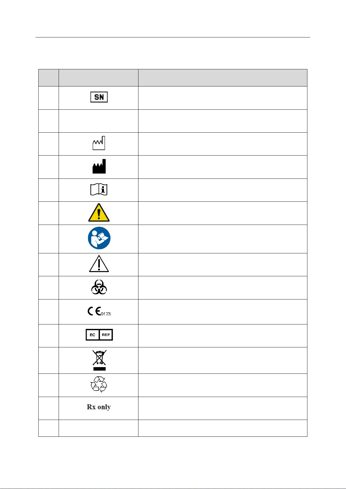
1 Serial Number
2
P/N
Part Number
3 Date of Manufacture
4 Manufacturer
5 Operating instructions
6
Warning
(Background: Yellow; Symbol & outline: Black )
7
Refer to User Manual
(Background: Blue; Symbol: White)
8
Caution
9 Biological Risks
10
CE Marking
11
Authorized Representative in the European Community
12
Disposal method. Indicates that the equipment should be
sent to special agencies according to local regulations for
separate collection after its useful life.
13
General Symbol for Recovery / Recyclable
14
Caution: Federal (U.S.) law restricts this device to sale by or
on the order of a physician.
15
IPX7
No harm for short time immersion
2.3 Labeling Symbols
The following labels are used on the system:
- 7 -
Page 14
Acclarix AX3 Series Diagnostic Ultrasound System User Manual Safety
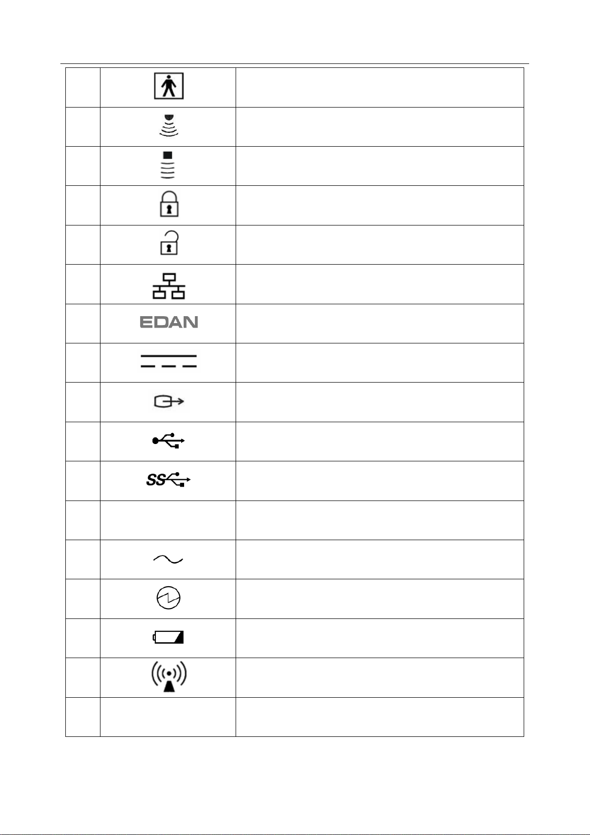
16
Type BF Applied Part
17
Transducer connector
18
Pencil Transducer connector (reserved)
19
Transducer lock
20
Transducer unlock
21
Network port
22
Trademark
23
Direct current
24
S-Video Output port
25
USB 2.0 port
26
USB 3.0 port
27
HDMI
HDMI port
28
AC Power Indicator
29
System Working Indicator
30
Battery Indicator
31
Non-ionizing electromagnetic radiation
32
FCC ID: SMQAX3EDAN
Federal Communications Commission:
FCC ID:SMQAX3EDAN
- 8 -
Page 15
Acclarix AX3 Series Diagnostic Ultrasound System User Manual Safety
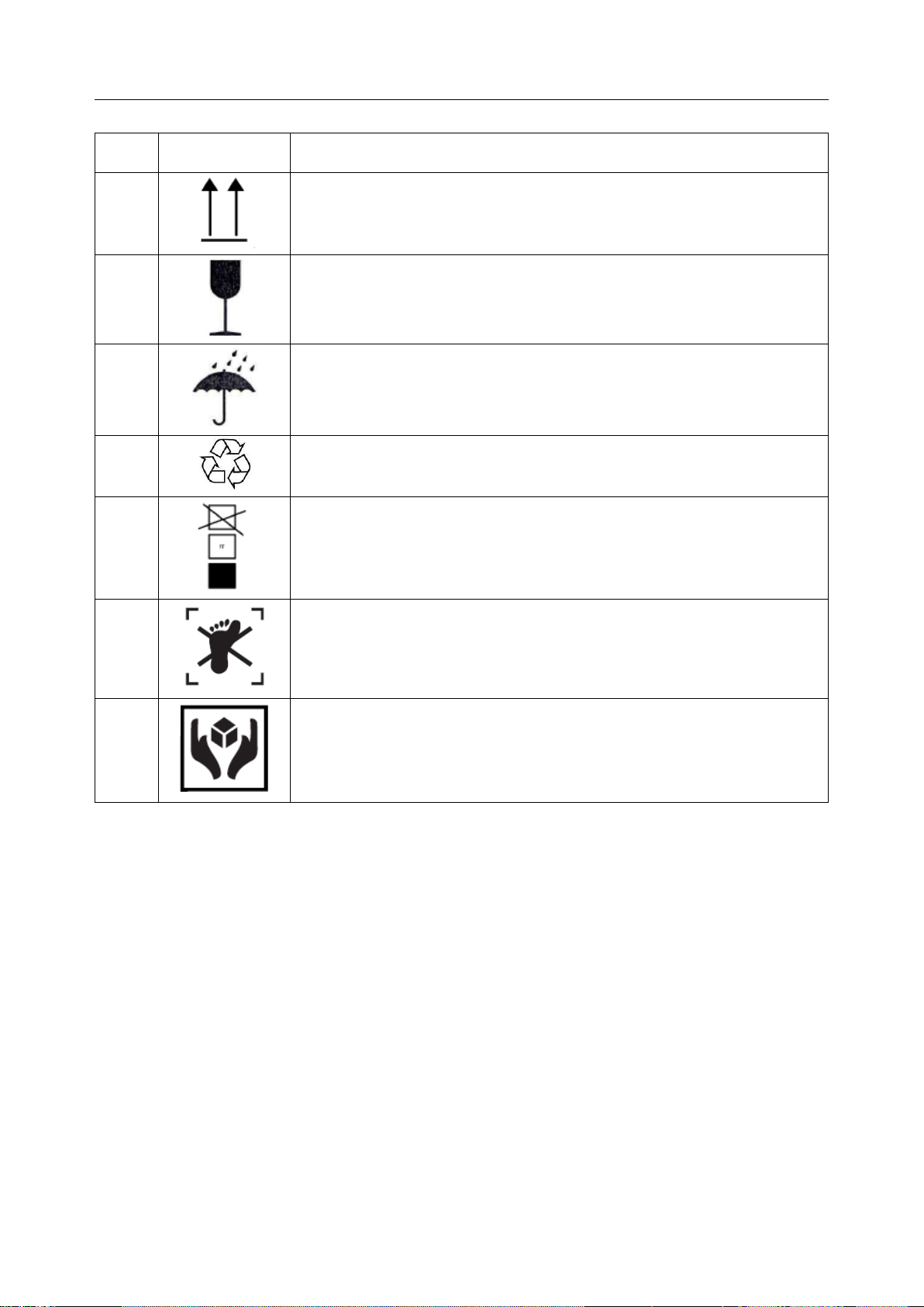
No.
Symbol
Definition
1
This way up
2
Fragile
3
Keep away from rain
4
General Symbol for Recovery / Recyclable
5
Stacking limit by number
6
Do not step on!
7
Handle with care
The following labels are used on the packaging:
NOTE:
The user manual is printed in black and white.
- 9 -
Page 16

Acclarix AX3 Series Diagnostic Ultrasound System User Manual Getting Started
Model
Angle/Depth
Description
BGK-C5-2
20° , 28°, 40°
For use with the C5-2Q,
Supports: 14G-23G
BGK-L40UB
34°, 43°, 53°, 66°
For use with the L17-7Q,
Supports: 14G-23G
BGK-001
1.0cm, 1.5cm, 2.0cm
For use with the L17-7Q,
Supports: 21G
BGK-002
38° , 46°, 58°
For use with the L12-5Q,
Supports: 14G-23G
BGK-003
1.0cm, 1.5cm, 2.0cm
For use with the L12-5Q,
Supports: 21G
BGK-CR10UA
2°
For use with the E8-4Q,
Supports: 16G, 18G
3 Getting Started
3.1 System Configuration
Standard Configuration:
The system is shipped with the following components:
1 main unit
1 AC adapter
1 power cord
1 rechargeable lithium battery
1 USB disk
1 bottle of coupling gel
1 basic user manual and 1 advanced user manual
1 packing list
Options:
The following options are also available:
Transducers:
C5-2Q, L12-5Q, E8-4Q, P5-1Q, L17-7Q
Needle Guide Bracket Kit
2nd rechargeable lithium battery
Footswitch
Suitcase
Table 3-1 Needle Guide Bracket Kits
- 10 -
Page 17

Acclarix AX3 Series Diagnostic Ultrasound System User Manual Getting Started
Printer Type
Printer Model
Interface
Color Video Printer
SONY UP-25MD
S-Video
SONY UP-D25MD
USB
B/W Video Printer
SONY UP-X898MD
USB
Report Printer
HP Officejet Pro 251dw
USB
HP LaserJet Pro 200 color M251n
USB
HP LaserJet CP1525n Color
USB
HP Deskjet Ink Advantage 2010
USB
HP Deskjet 1010
USB
HP Deskjet 1510
USB
HP LaserJet 400 M401d
USB
HP DeskJet Ink Advantage Ultra 2029
USB
HP DeskJet 1112
USB
Canon E518
USB
Canon iP2780
USB
HP LaserJet Pro MFP M126nw
USB
EPSON L310
USB
HP DeskJet 1050
USB
HP DeskJet 2050
USB
HP LaserJet M252n
USB
EPSON L130
USB
Supported Peripheral Accesories:
The recommended printers are listed as follows:
Only the recommended printers listed above are verified by EDAN. Therefore, it is suggested to only
use these printers. Use of other printers should comply with IEC 60950 or IEC 60601-1. Edan is not
responsible for the accuracy of other printers.
Table 3-2 Printer List
WARNING
- 11 -
Page 18
Acclarix AX3 Series Diagnostic Ultrasound System User Manual Getting Started
1
2
3
4
5
6 7 6 7 8
11 9 10
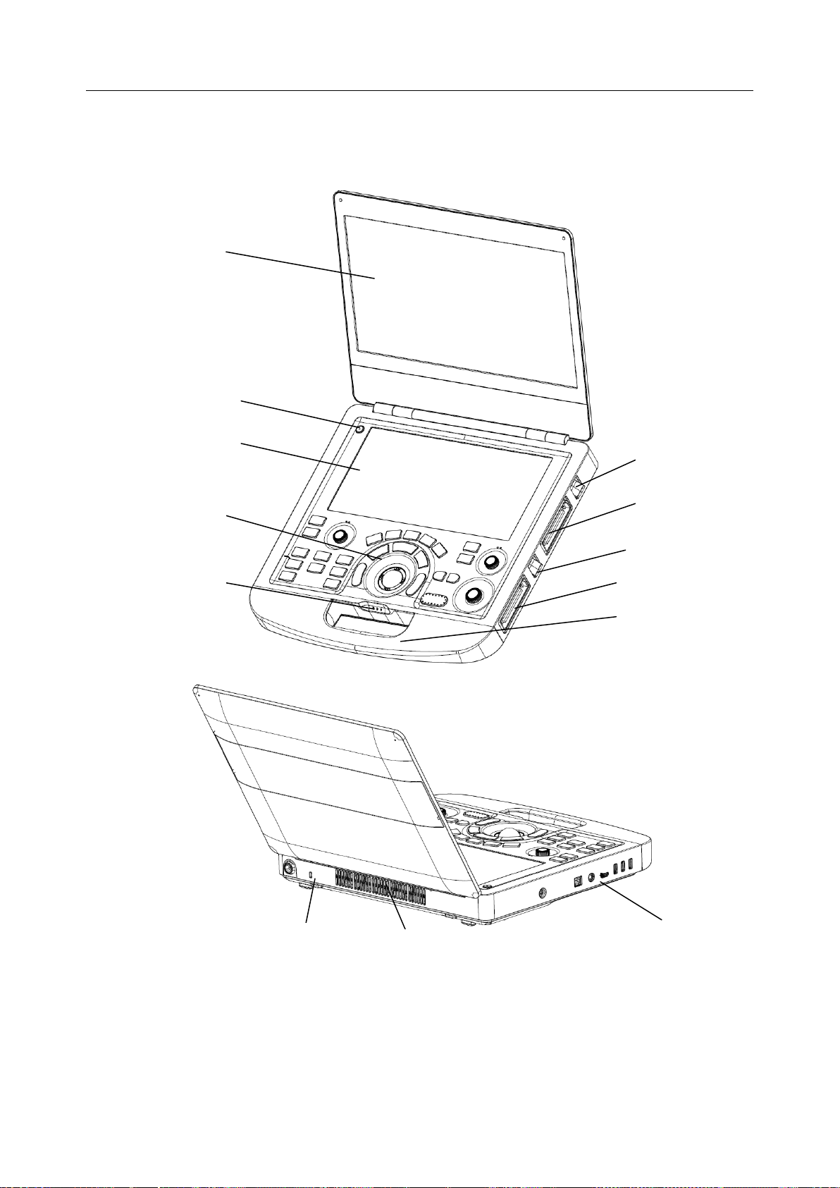
3.2 System Overview
3.2.1. Main Unit
Figure 3-1 Main Unit
- 12 -
Page 19

Acclarix AX3 Series Diagnostic Ultrasound System User Manual Getting Started
No.
Name
Description
1
Monitor
Display the images and parameters during
scanning.
2
Power Switch
Power on/off the system.
3
Touch Screen
Use to control operation and activate
functions.
4
Control Panel
Use to control the operation .
5
AC Power Indicator
It illuminates when the system is connected to
AC power.
It is off when the system is no connected to
AC power
System Working Indicator
It illuminates when system is running, and it is
off when the system is shutdown.
Battery Indicator
It is off when no battery is connected or
battery is fully charged.
It illuminates in orange when battery is low.
It illuminates in green when the system
operates on battery power or the battery is
charging.
6
Transducer Locking Lever
Use to lock or unlock the transducer.
7
Transducer Port
Used for connecting a transducer to the
system.
8
Handle
Used for carrying the system.
9
Safety Lock Connector
Used for connecting a safety lock to the
system.
10
Vents
Used for heat dissipation and ventilation.
11
I/O Ports
Use to connect the I/O extend modules.
1. Ensure system vents are clear and unobstructed. Bad ventilation will result in high
system temperature. When the high temperature warning "System Temperature is
High. Please check the system for good ventilation" displays, refer to section 13.2
Troubleshooting for the specific troubleshooting steps.
2. Excessive dust and dirt could clog internal airflow and cause overheating. Do not use
in a dusty environment.
Table 3-3 Main Unit Description
CAUTION
- 13 -
Page 20
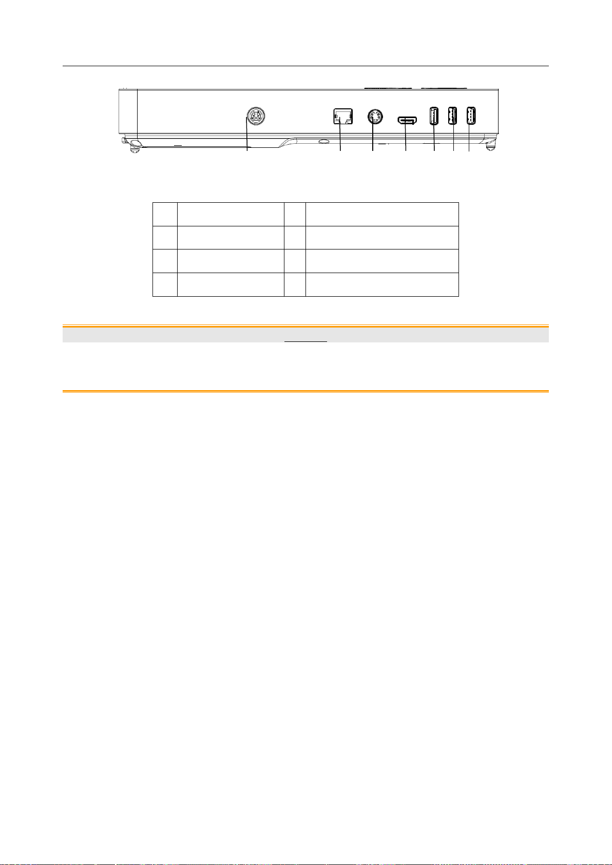
Acclarix AX3 Series Diagnostic Ultrasound System User Manual Getting Started
1.
Power supply
2.
Network port
3.
S-Video output port
4
HDMI port
5
USB 3.0 port
6
USB 2.0 port
7.
USB 2.0 port
1 2 3 4 5 6 7
I/O Ports on the left panel:
Figure 3-2 I/O ports
Table 3-4 I/O Ports
Caution
1. The HDMI port does not support "hot plug" feature. Please connect the external
display to the HDMI port before starting the ultrasound system. Otherwise the
external display may be unrecognized or display abnormally.
- 14 -
Page 21
Acclarix AX3 Series Diagnostic Ultrasound System User Manual Getting Started
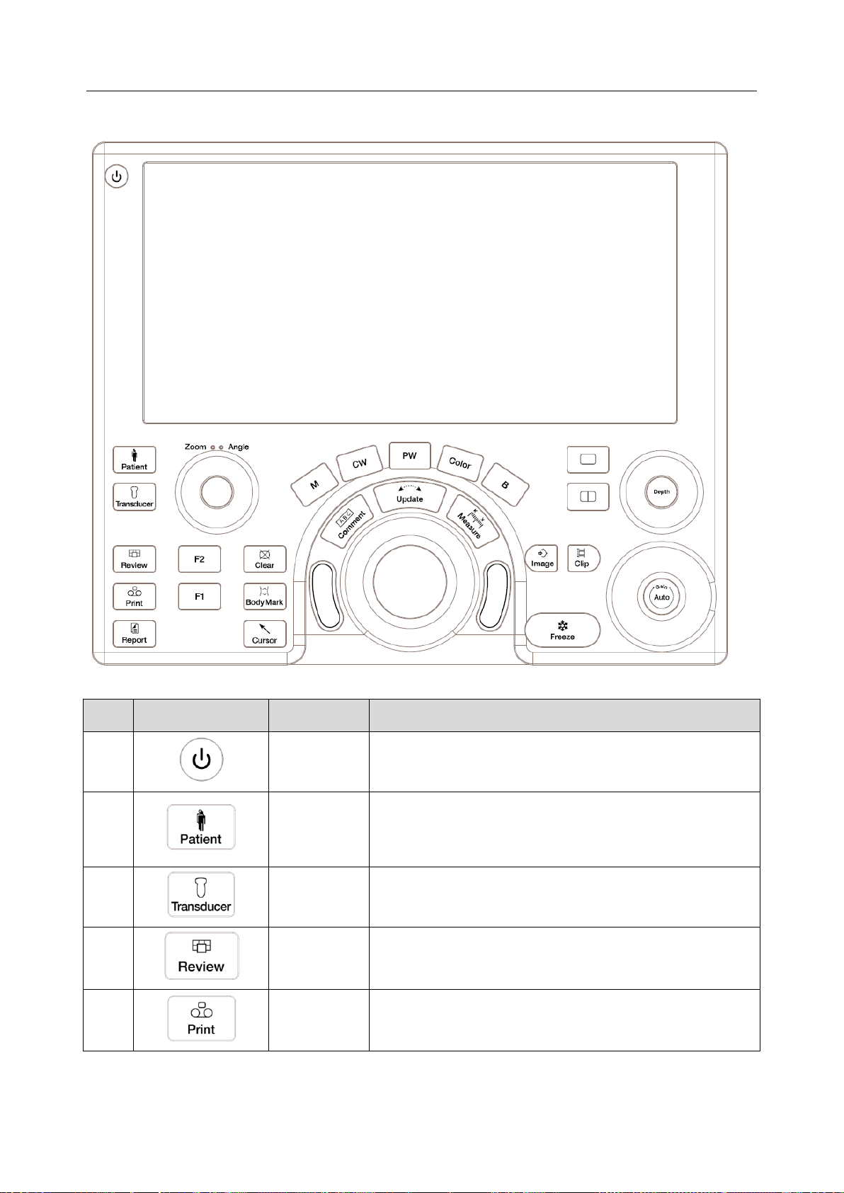
No.
Key
Name
Description
1.
Power switch
Press to power on/off the system
2.
Patient
Invokes the Patient Information Screen typically used to
start/end exams or to modify patient information during an
exam. See section 4.1.
3.
Transducer
Press to switch transducers or exam presets.
4.
Review
Press to enter exam database or image review mode. See
section 9 for details.
5.
Print
Press to print images via the connected video printer.
3.2.2. Control Panel
Figure 3-3 Control Panel
- 15 -
Page 22
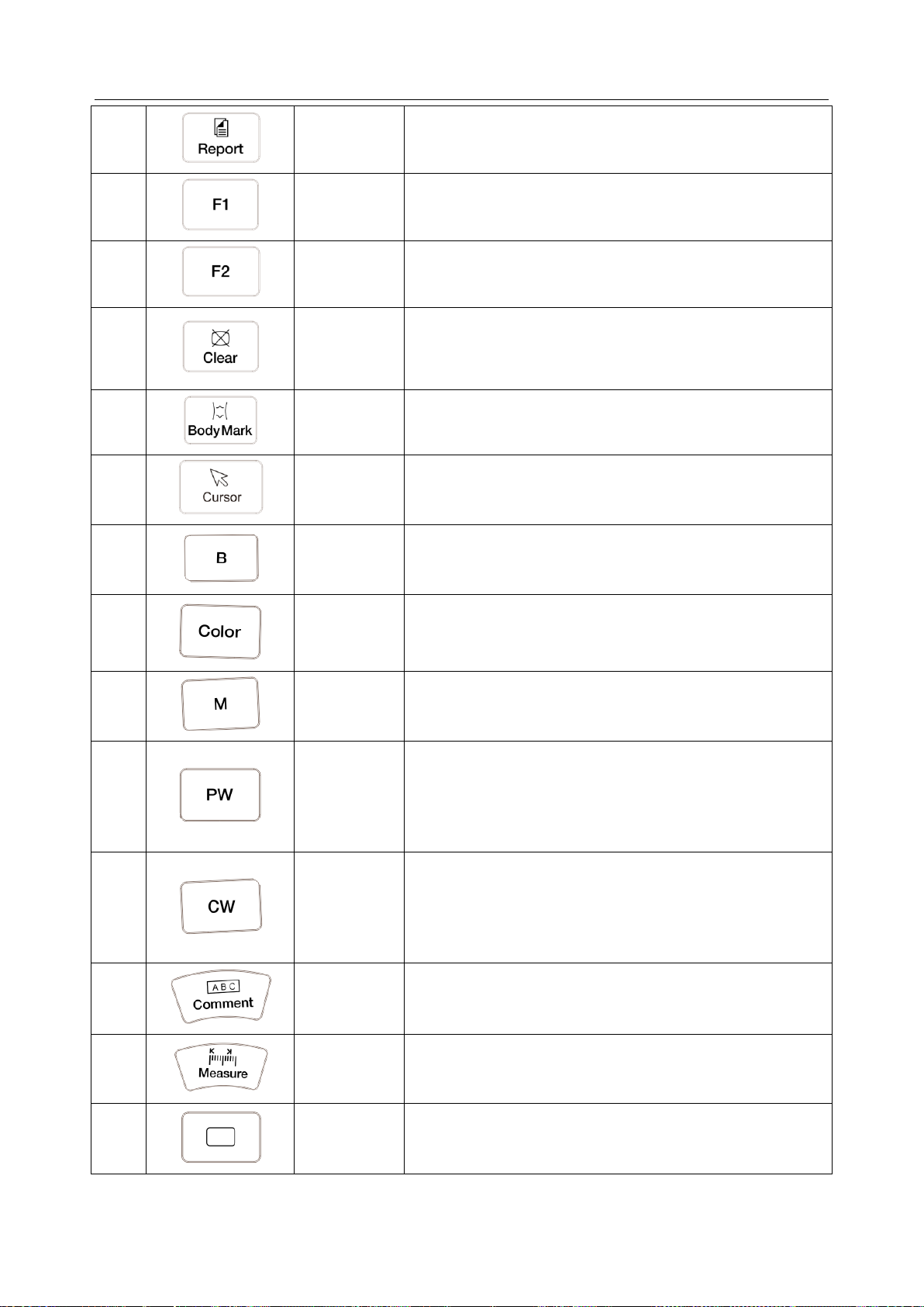
Acclarix AX3 Series Diagnostic Ultrasound System User Manual Getting Started
6.
Report
Press to display the report page.
7.
F1
User-defined button
8.
F2
User-defined button
9.
Clear
Press to clear all the measurements, calculations,
comments, and body marks displayed on the current
image.
10.
Body Mark
Enters or exits the Body Mark function. See section 7.2 for
details.
11.
Cursor
Press to hide or display the mouse cursor.
12.
B
Press to return to B-mode imaging from any other imaging
modes. See section 5.1 for details.
13.
Color
Press to enter or exit Color Mode. See section 5.2 for
details.
14.
M
Press to enter or exit M Mode. See section 5.5 for details.
Use the trackball to adjust the M sample line.
15.
PW
Press to get the sample line. Use the trackball to adjust
the position of the sample line. Press it again to display
the Doppler strip.
See section 5.3 for details.
16.
CW
Press to get the sample line. Use the trackball to adjust
the position of the sample line. Press it again to display
the Doppler strip.
See section 5.4 for details.
17.
Comment
Enters or exits the Comment function. See section 7.1 for
details.
18.
Measure
Invokes the Measure function for Generic and Application
Measurements. See section 8 for details.
19.
Single
Press to display the currently active side of Dual image as
a single image. See section 7.3 for details.
- 16 -
Page 23
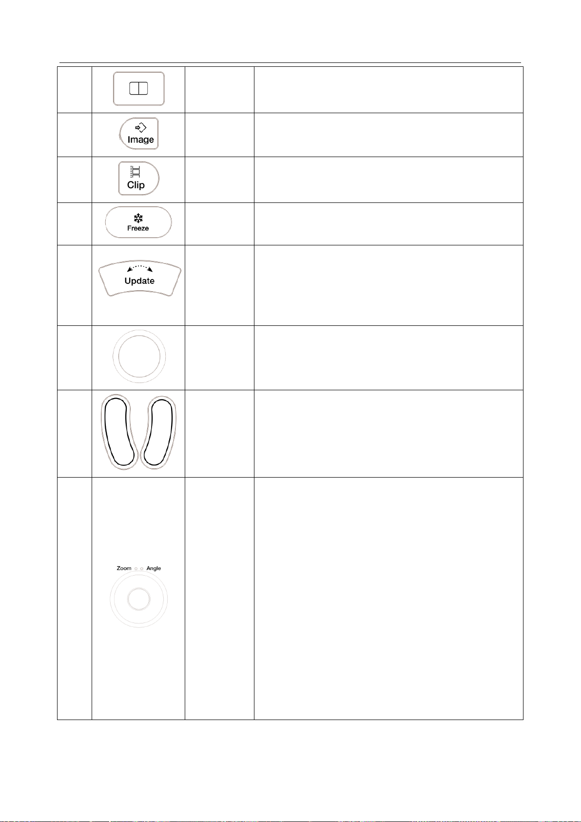
Acclarix AX3 Series Diagnostic Ultrasound System User Manual Getting Started
20.
Dual
Enters dual split screen. Each single press on it toggles
between two images. See section 7.3 for details.
21.
Store Image
Press to store static images.
22.
Store Clip
Press to store clips.
23.
Freeze
Press to switch between the frozen and real-time states.
24.
Update
In measurement, pressing <Update> switches the active
side of calipers. See section 8 for details.
When Spectral Doppler strip is displayed, pressing
<Update> allows switching between live acquisition of the
Doppler strip or the reference image.
25.
Trackball
Move the trackball to change the cursor position, adjust M
mark position in M mode, adjust sample line position in
PW mode, etc.
26.
Trackball
keys
Two trackball keys provide a wide variety of functions
depending on the system state (e.g., selects a start or end
point of a measurement, selects menu items on the
screen, etc). For the convenience of introduction, we call
them <Set> throughout this user manual.
27.
Zoom/Angle
The functions of this knob vary with system functions.
When one function is activated, its indicator illuminates.
Then rotate to zoom an image or adjust the angle.
For example:
In B and Color mode, the Zoom function is auto activated
and its indicator illuminates. Rotating the knob will zoom
images.
In PW or CW mode, the Angle function is auto activated
and its indicator illuminates. Rotating the knob will adjust
the Doppler scale to account for the angle between the
Doppler cursor and the blood flow.
When Comment or Body Mark function is enabled, the
Angle function is auto activated and its indicator
illuminates. Rotating the knob will adjust the angle of
comment arrow or the transducer icon.
- 17 -
Page 24
Acclarix AX3 Series Diagnostic Ultrasound System User Manual Getting Started
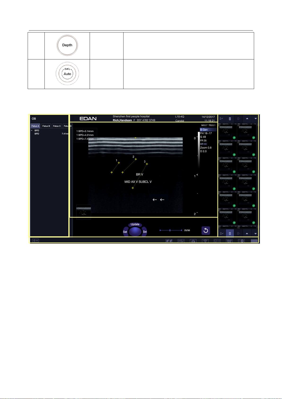
28.
Depth
Rotate to adjust the depth of the image displayed.
29.
Auto/Gain
Press to optimize B image automatically.
Rotate to change the gain of images.
①
④
⑤
②
③ ⑤ ⑥
Table 3-5 Buttons on Control Panel
3.2.3. Screen Layout
Figure 3-4 Main Screen Display
① Information Field
The top line of this field contains your hospital/institution name. Please see Section
Set-up
The second line of this field contains the patient name, gender, age and ID, as entered through the
Patient Information screen.
This field also contains data fields for:
for information on customization.
The currently active transducer
The currently active preset
System date and time.
② Image Field
The ultrasound image appears in the Image field, under the Information field. The Image field also
contains information typically associated with the image, such as depth, TGC, maps, image
parameters, MI and TI.
11.1.1 General
- 18 -
Page 25
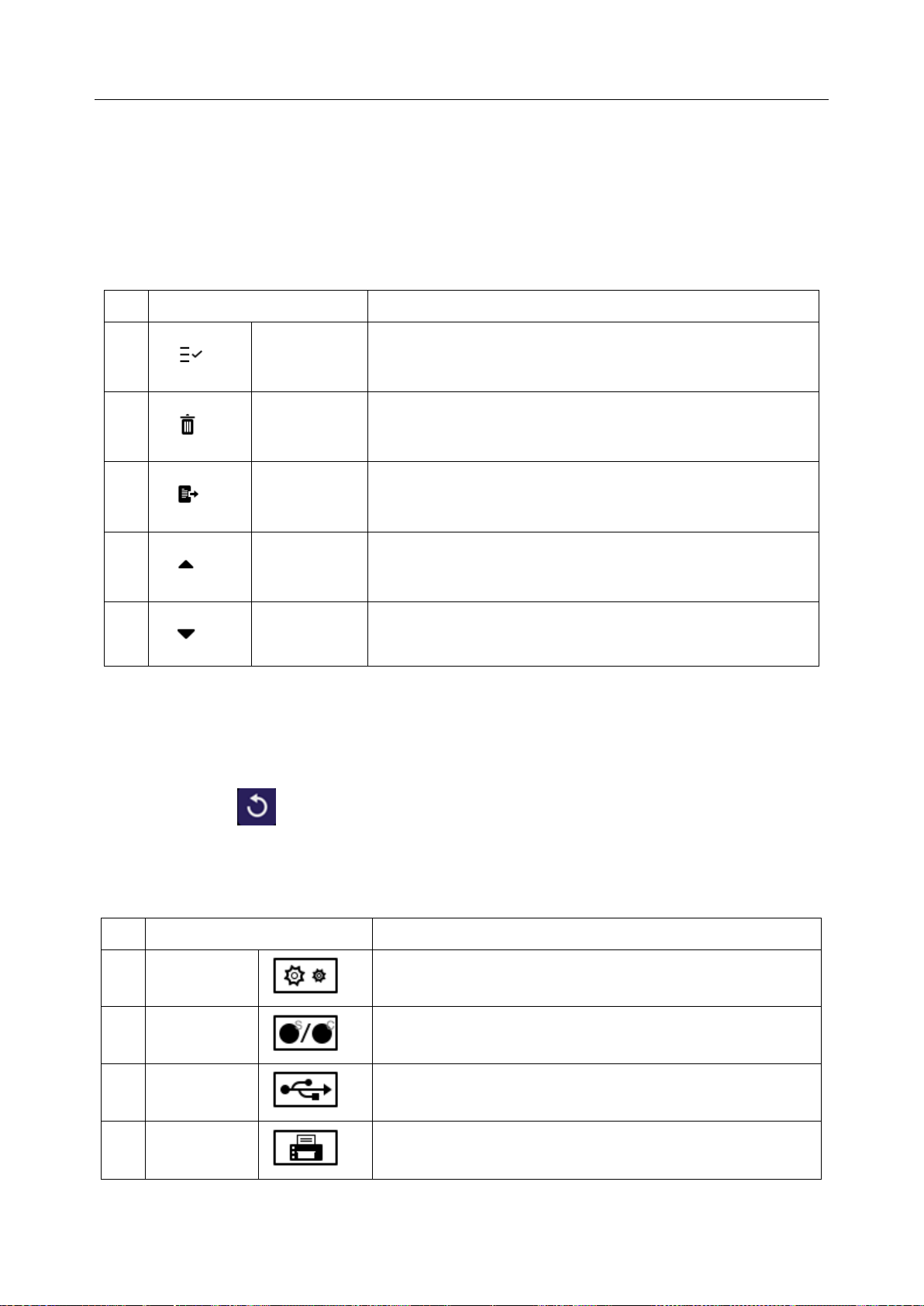
Acclarix AX3 Series Diagnostic Ultrasound System User Manual Getting Started
No.
Shortcut Keys
Description
1 Select All
Selects all the displayed static images and clips.
2 Delete
Deletes the selected static images and clips.
3 Export
Exports the selected static images and clips to removable
storage devices.
4 Page Up
Turns the page up when more than one page of images are
displayed.
5 Page Down
Turns the page down when more than one page of images
are displayed.
No.
Icons
Description
1
Utility icon
Provides access to system setup, screen adjust,
connectivity, maintenance, etc.
2
Image Store
icon
Displays the number of static images and clips stored in the
current exam.
3
USB icon
USB disk available.
4
Printer icon
Printer available.
Symbol is in green when printing in progress.
③Mini Report
The left side of the screen displays a “mini-report” which displays measurements performed during the
current exam.
④Thumbnail Field
The right side of the screen displays thumbnail images of all statics and clips captured for currently
active exam or when in Review. This field also contains several shortcut keys for selecting, viewing,
deleting, exporting images. See the below for details:
⑤ Soft Keys Field
The soft keys filed is displayed below image field and above status bar. This field displays:
The illustration of trackball and trackball keys.
Cine bar when the system is frozen.
An "Exit" icon . Only displayed in review mode. Clicking on this icon will exit the review
mode.
⑥ Status Bar
The bottom of the screen is used to display icons that provide system status. These include:
- 19 -
Page 26
Acclarix AX3 Series Diagnostic Ultrasound System User Manual Getting Started
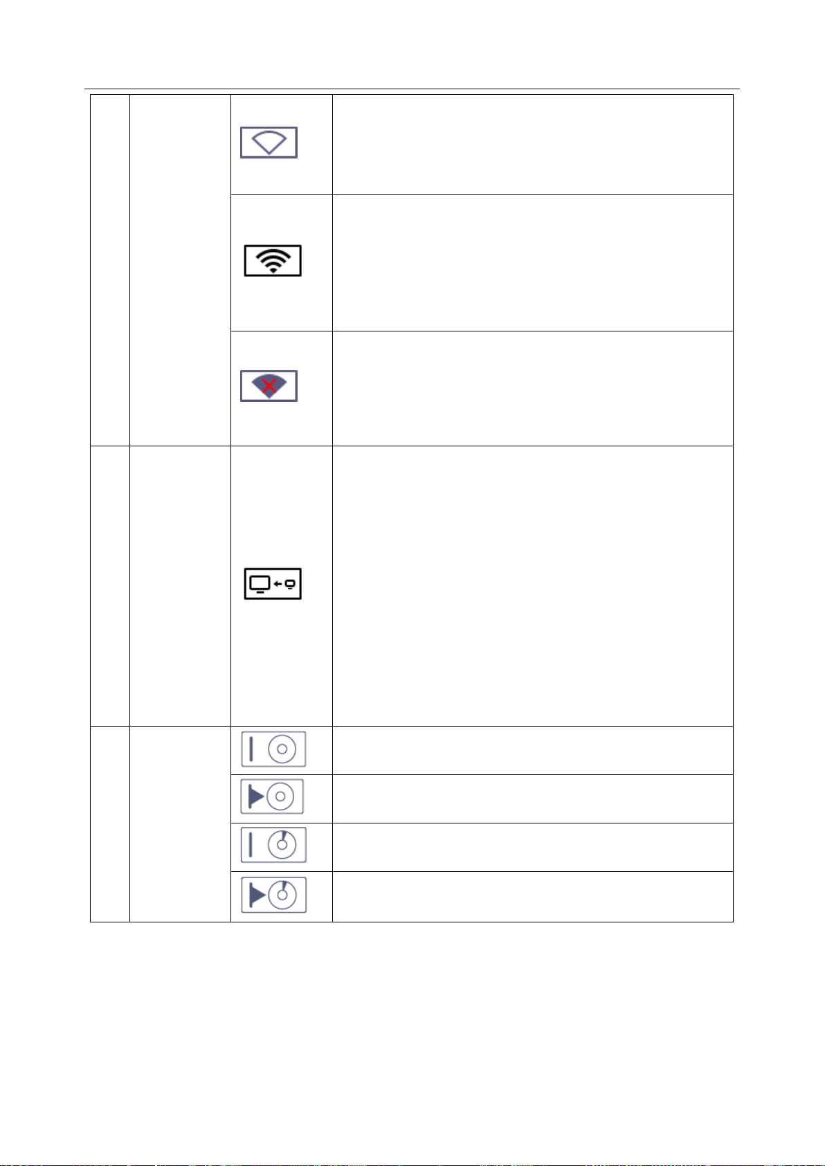
5
Wi-Fi icon
Wi-Fi function is enabled, but no WI-FI network is
connected.
No WI-FI icon will be displayed when Wi-Fi function is
disabled in Connectivity setup.
Wi-Fi network is connected.
Clicking on this icon shows a list of available Wi-Fi networks.
Selecting an available network displays a dialog box for
entering password. Clicking on the "WiFi: Turn off" button
above the list will disconnect the currently connected WI-FI
network.
WI-FI network is disconnected.
Clicking on this icon shows a "WiFi: Turn on" button.
Clicking on this button shows a list of available Wi-Fi
networks. Selecting an available network displays a dialog
box for entering password.
6
Network
Transfer
Status icon
The network transfer status icon shows the transfer statuses
of the DICOM network.
Outline in grey color: At least one DICOM network is
configured for file transfer.
Outline in green color: Data exchange with a DICOM
Server.
Outline in red color: No DICOM network is configured
for file transfer.
Clicking on this icon displays a queue of exam or image
transfers and as well as the transfer status of each exam or
image including refused, pending, active, succeeded and
failed.
7
Hard Drive
icon
Hard drive available.
Hard drive data exchange, symbol in green.
Hard drive 95% full, symbol in red.
Hard drive 95% full with data exchange, symbol in red.
- 20 -
Page 27
Acclarix AX3 Series Diagnostic Ultrasound System User Manual Getting Started
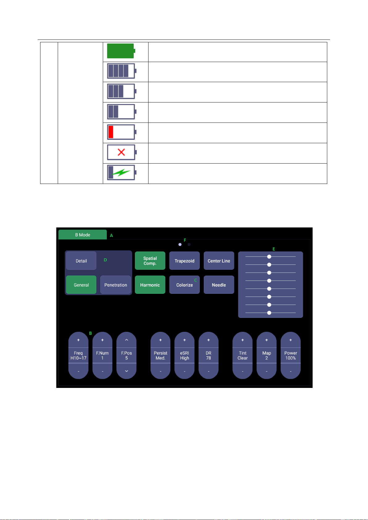
8
Battery icon
Battery fully charged, symbol in green.
Battery more than 80% charged.
Battery 60%-80% charged.
Battery 40%-60% charged.
Battery low, symbol in red.
Battery removed.
Battery charging.
3.2.4. Touch Screen
The Touch Screen contains controls that vary depending on the active imaging mode or function.
There are several types of controls used by the touch screen, as illustrated below:
Figure 3-5 Touch screen of the System
A. Tabs: Each imaging mode that is active has a tab at the top of the touch screen. Usually, the
imaging mode that was most recently activated is the top tab and has priority. Pressing on any
other tab will bring it to the top and provide access to the controls available for that imaging
mode.
B. Paddle: Pressing on the top or bottom of a paddle changes the control setting by one value.
Pressing anywhere on the control and swiping across it will continuously change the value.
C. Push button: This can either be an on/off control (like “Colorize”).
D. Radio Buttons: A collection of buttons where only one is active at any time. Activating one will
- 21 -
Page 28

Acclarix AX3 Series Diagnostic Ultrasound System User Manual Getting Started
de-activate all others.
E. TGC: The B-mode tab has a specialized control for TGC. Each slider can be dragged
horizontally and individually. Dragging vertically down across the sliders will set all sliders.
F. Pages: When a tab has multiple pages of controls, each page is represented by a dot at the
top of the page. The current page is indicated by a filled-in dot. You can move between pages
by dragging your finger horizontally across the dots. These dots do not appear when there is
only one page in the current tab.
3.2.5. Trackball
The trackball operation is easy and convenient. It can achieve the following functions:
Move the measurement cursor during measurement.
Move the comment cursor in the comment status.
Move the M Mark in the B+M mode.
Move the scan area of Color mode, increase or decrease the size of scan area of Color mode.
Move the sample line in the PW/CW mode.
Realize single frame playback in the frame-by-frame playback status.
Move the zoomed window in the zoom status.
NOTE:
1. Please be gentle when running the trackball.
2. Please keep the surface of trackball clean.
- 22 -
Page 29
Acclarix AX3 Series Diagnostic Ultrasound System User Manual Getting Started
3.3 System Preparation
3.3.1. Battery Use
The system may come with two lithium-ion batteries depending on your order. One fully charged
battery can run the system for approximately 1 hour and two fully charged batteries together can run
the system for approximately 2 hours, depending on use. The batteries are automatically charged
when the system is plugged in.
The system has two battery compartments which are identified by letter A and B respectively. The
battery icon of the battery which is installed in battery compartment A is displayed with letter A on it
and the battery icon of the battery which is installed in battery compartment B is displayed with letter B
on it.
CAUTION
1. If the system will remain unused for more than one week, charge the battery to at least 75%
capacity, take the battery out and store the system and battery separately.
2. During long term storage, the battery should be charged at least once every 6 months to ensure
battery capacity is more than 75%.
3. Only use Edan supplied battery.
To install the battery:
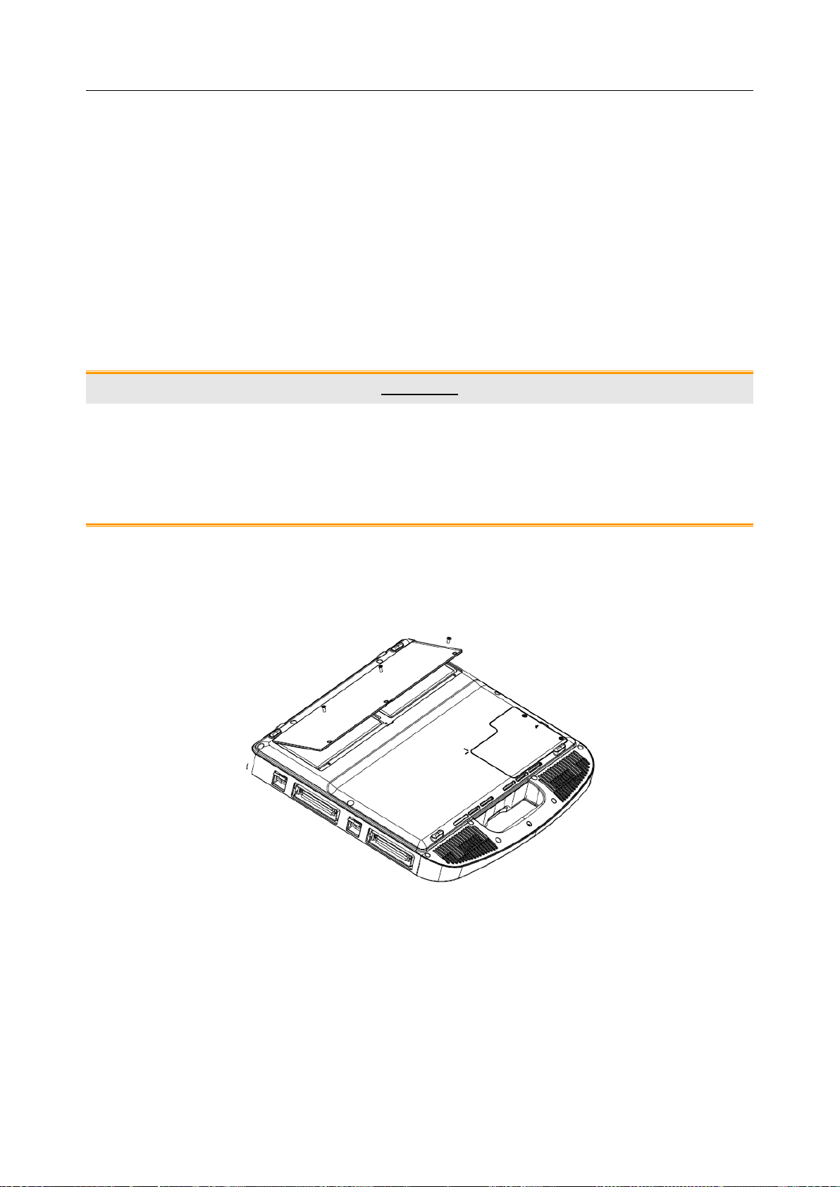
1. Turn off and unplug the system.
2. Close the monitor, turn the system upside down and rest it on a flat stable surface.
3. Unscrew the three screws securing the battery door, and remove the battery door.
Figure 3-6 Removing battery door.
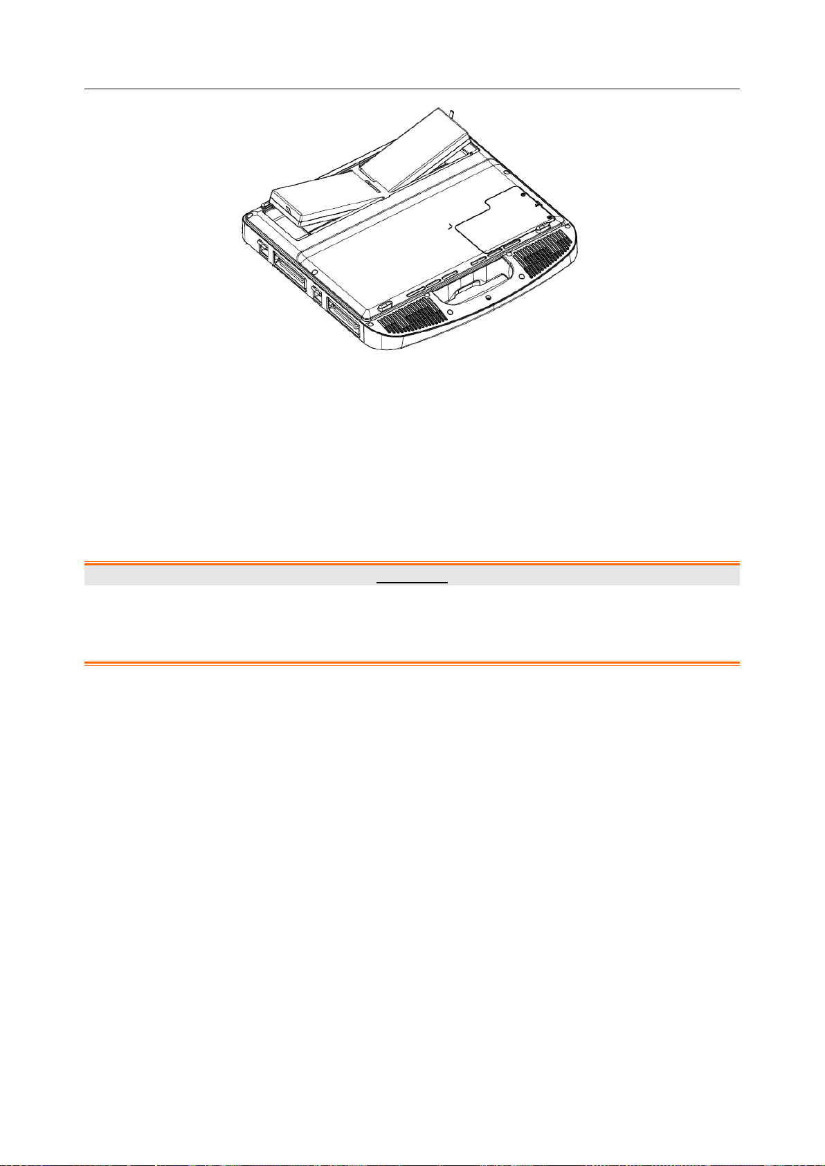
4. Put the battery gently to battery compartment.
- 23 -
Page 30
Acclarix AX3 Series Diagnostic Ultrasound System User Manual Getting Started
Figure 3-7 Installation of the Battery
5. Close the battery door and screw the three screws.
To remove a battery:
1. Turn off and unplug the system.
2. Close the monitor, turn the system upside down and rest it on a flat stable surface.
3. Unscrew the three screws securing the battery door, and remove the battery door.
4. Remove the battery.
5. Close the battery door and screw the three screws.
WARNING
1. When the battery capacity is ≤20%, the battery status icon turns red.
2. When the battery capacity is ≤10%, the system displays a prompt “Low Battery. The
system will shutdown in 3 mins. Please plug in the power supply immediately."
3.3.2. AC Power Use
When using AC power, position the system so that it is easy to disconnect it from AC power supply.
To connect AC power:
1. Connect the AC power cord with the power adapter.
2. Connect the DC power cord from the power adapter to the power connector on the system. Make
sure the side with a "Direction Indicating Dot" should face upside when connecting the DC power
connector, as the illustration below.
- 24 -
Page 31

Acclarix AX3 Series Diagnostic Ultrasound System User Manual Getting Started
Direction Indicating Dot
3. Push the power cord in firmly to ensure a secure connection.
4. Connect the AC power cord to a hospital-grade power outlet.
WARNING
1. Make sure the AC power supply complies with the following specifications: 100V-240V~,
50Hz/60Hz.
2. Only use a hospital grade, grounded, power outlet and plug. Do not use with an ungrounded
outlet.
3. Only use Edan supplied power adapter and power cord.
3.3.3. Transducer Connection
To connect a transducer:
Figure 3-8 Tansducer Locking Handle
1. Align the connector with the transducer port and carefully push into place.
2. Toggle the locking handle to the top position.
3. Do not allow the transducer head to hang free. Impact to the transducer head could result in
irreparable damage.
- 25 -
Page 32

Acclarix AX3 Series Diagnostic Ultrasound System User Manual Getting Started
Figure 3-9 Lock the tansducer locking handle
To disconnect a transducer:
1. Toggle the locking handle to the bottom position to unlock the transducer connector.
2. Firmly grasp the transducer connector and carefully remove it from the system port.
3. Store transducer in its protective carrying case prior to transport.
CAUTION
1. Do not touch the pins of the transducer connector.
2. Broken or bent connector pins can cause image artifacts. Do not use a transducer with broken or
bent pins.
3. Only disconnect a transducer when the system is shutdown or is frozen.
- 26 -
Page 33

Acclarix AX3 Series Diagnostic Ultrasound System User Manual Getting Started
3.3.4. Powering on/ off
To power on:
1. Connect the system to a hospital grade power supply, or use the battery as the power supply.
2. Press the Power on/off key on the top left of the control panel.
To power off:
1. Press the Power on/off key on the top left of control panel and the system displays a
confirmation dialog box.
2. Select “Shut Down” from the confirmation dialog box.
If the system is unresponsive, a long press of the Power on/off key will shut down the system directly.
NOTE:
1. Turn off and unplug the device after use.
2. Please unplug the AC adapter from the power socket and disconnect the battery prior to storage.
Sleep mode
The system will enter a sleep mode that maintains exam information while using minimal power.
There are three events that can invoke sleep mode:
Close the cover of the system without powering-off the system.
No user input for a configurable amount of time. Please see System Set-up to configure this
time.
Pressing the Sleep button on the confirmation dialog box when powering off.
Figure 3-10 Confirmation Dialog Box When Power off
There are two events that can exit sleep mode:
Open the cover of the system.
Press the Power on/off key.
- 27 -
Page 34

Acclarix AX3 Series Diagnostic Ultrasound System User Manual Exam Operation
4 Exam Operation
4.1 How to Start an Exam
1. Press the <Patient> key and enter patient information, or select a scheduled patient from the
modality worklist.
If there is no previous exam, pressing the <Patient> key will bring you directly to the Patient
Information Page (see figure 4-2 below).
If a previous exam is still active you will see the following dialog:
Figure 4-1 Exam Confirmation Dialog
The following options are available:
End Exam: select this to end the current exam and return to live imaging to start a new
exam.
Edit Current: This lets you edit the Patient Information for the current exam. It does not
start a new exam.
New Exam: Select this to start a new exam.
If Same Patient is checked, selecting New Exam will end the previous exam and create a
new exam for the same patient. The main screen will display the Patient Information Page
with the previously entered patient information except for the exam accession number.
Changing the patient information for one exam will not impact the others.
If Same Patient is unchecked, selecting New Exam, a blank Patient Information Page will
be displayed for entering patient information for a new patient.
Tick the check box of Same Patient when operating multiple exams for same patient.
Cancel: Exits the dialog without starting or ending an exam.
2. Press OK on the touch screen or press the <Patient> key again to start scanning.
3. To change transducer or exam preset, press the <Transducer> key, and then the Transducer
touch screen provides you choices of available transducers and exam presets, as the figure
below.
- 28 -
Page 35

Acclarix AX3 Series Diagnostic Ultrasound System User Manual Exam Operation
Figure 4-2 Example of Transducer Touch Screen
4.2 How to End an Exam
There are two ways to end an exam:
Pressing the <Patient> key, as described above, and then selecting New Exam. This both
ends the exam and displays the Patient Information Page for the next exam.
Pressing the <Patient> key, as described above, and then selecting End Exam. This brings
up a dialog to confirm you want to end the exam, but does not invoke the Patient Information
Page for the next exam.
4.3 How to Restart an Exam
1. Select an exam from the Exam Database within the time limit selected in Patient Set-up menu.
For the setting of time limit, refer to section
2. Press Restart on the touch screen to continue/edit the exam that was performed on the selected
patient. You can also modify the patient information by pressing <Patient>-->Edit Current.
11.1.2 Patient Set-up
.
4.4 The Patient Information Page
The Patient Information Page is used to enter or modify patient demographic data. The following
figure is an example:
- 29 -
Page 36

Acclarix AX3 Series Diagnostic Ultrasound System User Manual Exam Operation
Figure 4-3 Patient Information Page(OB Exam)
The top three lines are for entering the patient last name, first name, ID, exam accession number, and
DOB (Date-of-Birth) or age. If date of birth is entered, the age is automatically calculated.
Note:
By default, the patient name has two fields: family name and given name. It can be configured to be
one field in the Patient Setup screen (See section 11.1.2 for detail).
The next line displays tabs of multiple exam presets, and the associated patient information fields are
displayed below this line. The patient information needed to fill in changes with different exam presets.
All the possible patient information fields you may need to fill in are listed below:
Gender: Select the patient‟s gender: “M” (Male), “F” (Female), “O” (Other), or “<blank>”.
LMP: Last Menstrual Period (yyyy/mm/dd or mm/dd/yyyy), If LMP is entered then GA and EDD
are calculated. Entering EDD does not impact LMP. An LMP more than 300 days ago is
considered invalid.
GA: Gestational Age (xxWyD), it is autocalculated when LMP or EDD is entered (only in OB
Exam). A GA of more than 42W6D is considered invalid and not displayed.
EDD: Estimated Date of Delivery (yyyy/mm/dd or mm/dd/yyyy).EDD is autocalculated when
LMP is entered.
Fetus: Enter 1 up to 4 for multiple gestations.
G/P/A: G stands for Gravida, P stands for Para and A stands for Aborta. Enter values for each
in the fields separated by slashes.
Study Description: enter the study description.
Height: Enter the patient‟s height. The units can be set in the Patient section of Setup.
- 30 -
Page 37

Acclarix AX3 Series Diagnostic Ultrasound System User Manual Exam Operation
Weight: Enter the patient‟s weight. The units can be set in the Patient section of Setup.
BSA: Body Surface Area, it is auto-calculated and displayed when Height/Weight is entered.
HR: Enter the Heart Rate.
BP: Enter the Blood Pressure.
PSA: Prostate Specific Antigen.
PPSA Coefficient: Predicted Prostate Specific Antigen.
Ref. Physician: Enter the name of the Ref.Physician.
Dx. Physician: Enter the name of the Dx.Physician.
Operator: Enter the name of the person performing the exam..
CPT code: Current Procedural Terminology code.
Comment: Enter any additional comments.
While the Patient Information Page is displayed the following buttons are displayed on the touch
screen and Patient Information Page:
Figure 4-4 Patient Information Touch Screen
Press OK to exit the Patient information Page and save the patient information.
Press Cancel to exit the Patient Information Page without storing any of the entered data.
Press Clear All to clear all of the demographic fields except for name and ID.
- 31 -
Page 38

Acclarix AX3 Series Diagnostic Ultrasound System User Manual Exam Operation
4.5 Modality Worklist
Modality worklist provides a list of scheduled patients derived from a DICOM server. It is available only
when a DICOM server is configured and worklist is enabled.
When the modality worklist function is enabled and configured in DICOM connectivity setup screen,
the worklist is shown to the left of the Patient Information Page, as shown below.
Figure 4-5 Modality Worklist Display
The worklist is displayed on the left side of the Patient Information Page in two columns labeled
patient name and patient ID. Clicking on the header of each column will sort the list for the
corresponding column.
The worklist shows all scheduled ultrasound exams within the date-range specified in the DICOM
connectivity setup screen (See 11.2.2). Typing any text in the Filter field will filter the list to exams
that contain the entered text.
Update: Press to query the patient data and update the list manually.
Hide List: Press to hide the list with only a Show List button displayed. Press the Show List button to
display the list and other buttons.
Select one patient from the list and the detailed patient information is entered into the associated fields
on the patient information page, with the option to edit or complete. Then press OK on the touch
screen to start an exam.
- 32 -
Page 39

Acclarix AX3 Series Diagnostic Ultrasound System User Manual Imaging
Name
Control
Description
TGC
The Time Gain Compensation control (TGC) adjusts the gain
of the image at different depths. Each slider can be adjusted
separately, or you can drag your finger vertically to adjust all
sliders to a new setting.
Dynamic
Range
The Dynamic Range, or log compression, adjusts how echo
intensities are converted to brightness. A high dynamic
range will display more shades of gray, while a low dynamic
range will display fewer shades of gray and a more contrasty
image.
eSRI
eSRI is Speckle Reduction Imaging. There are 4 levels: Off,
Low, Med. and High. High level provides more aggressive
speckle reduction.
Persistence
Persistence averages frames together to reduce random
noise. There are 4 options: Off, Low, Med., and High. The
persistence level corresponds to the number of frames
averaged. The frame rate is unchanged.
Frequency
Frequency allows selection of the fundamental or harmonic
frequencies used for imaging. The Harmonic option must be
invoked to access the harmonic frequencies. Frequency
selection is available during live imaging.
5 Imaging
5.1 B-mode
5.1.1. Using B-mode
1. Press <B> on the console to enter B mode.
2. Perform the image scanning.
3. Adjust Image parameters to optimize the image.
5.1.2. B-mode Image Optimization
The following touch controls can be used to optimize the B-mode image.
- 33 -
Page 40

Acclarix AX3 Series Diagnostic Ultrasound System User Manual Imaging
Harmonic
The Harmonic control invokes and exits harmonic imaging.
While in harmonic imaging the control is highlighted and an
„H‟ is displayed in the B-mode frequency field. Depending on
the transducer, there may be multiple harmonic frequencies.
Spatial
Compounding
Spatial Compounding combines images derived from
multiple angles to reduce speckle, reduce shadow artifacts,
and enhance contrast resolution. Spatial compounding is an
on/off control.
Focus Number
Focus Number adjusts the number of foci is displayed. As
the number of foci increases, image uniformity across depth
will increase, but the frame rate will decrease.
Focus Position
Focus Position adjusts the depth of the focus or foci. Upward
presses move the focus shallower, regardless of the U/D
invert status of the image.
Gray Map
Gray Map adjusts the postprocessing map used on the
B-mode image. In general, higher map numbers correspond
to more contrast in the image.
Colorize
The Colorize control adds a color tint to the B-mode image.
Tint
The Tint control changes the color tint being used. There are
20 tint maps available. If Colorize had been off, changing the
Color map control will automatically activate it.
Left/Right
The Left/Right invert control is indicated by a backward R
and is used to toggle the left/right orientation of the image.
The Edan E orientation marker at the top of the image
switches with the left/right invert to match the orientation
marker on the transducer.
Up/Down
The Up/Down invert control is indicated by an upside-down
R and is used to toggle the up/down orientation of the image.
The TGC curve is also re-oriented with Invert On, so that the
top of the TGC curve corresponds to the top of the image on
the screen.
- 34 -
Page 41

Acclarix AX3 Series Diagnostic Ultrasound System User Manual Imaging
FOV
The Field of View control adjusts the image width. Full,
Large, Med. and Small settings are available. As the image
becomes narrower, the frame rate increases.
Steer
The Steer control is only available for linear transducers and
steers the B-mode image left or right, without moving the
transducer. This function can be particularly useful when
visualizing needles or other objects that are enhanced by a
perpendicular beam. Steer is not available if Spatial
Compounding or Trapezoid are turned on.
Trapezoid
The Trapezoid control activates the trapezoidal imaging on
linear transducers. It is a part of the B-mode function and
available in live imaging.
Image Type
B-mode supports presets for Detail, General, and
Penetration. See section
10.3.2
for more information.
Line Density
Adjusts the line density to optimize the lateral resolution for
the best possible image. The higher the line density, the
higher the lateral resolution, but the lower the frame rate.
Needle
Press to invoke the touch screen for Needle Enhancement
Visualization and Needle Biopsy Guide functions. See
section 6.4 and 6.5 for more information.
Acoustic power
Adjusts the acoustic output power of the activate transducer
and is only available in live imaging. Higher acoustic power
numbers correspond to increased sensitivity in the image
with improved penetration, but the ALARA principle should
be followed in actual clinical situations.
Center Line
Press to activate the Center Line function. Refer to section
6.6 for details.
Table 5-1 B-mode Touch Screen Controls
- 35 -
Page 42

Acclarix AX3 Series Diagnostic Ultrasound System User Manual Imaging
Name
Control
Description
Color Mode
Variation
A set of radio-buttons display the color modes that are available
on the current transducer, and let you switch between them.
See section 5.4.1 for details.
Scale
Scale adjusts the range of velocities that are displayed. Upward
presses increase scale and downward presses decrease it. It is
available in Velocity, PDI, and DPDI. It is not available in
Freeze/Cine.
5.2 Color Mode
5.2.1. Color Mode Variants
The system supports 3 types of Color Doppler imaging:
Color (Color Doppler): This is velocity Color Doppler that shows direction and velocity of flow.
Different colors represent different velocities and positive flow has different colors than
negative flow.
PDI (Power Doppler Imaging): PDI shows the power, or intensity, of the Doppler signal. PDI is
typically more sensitive to low levels of flow, but cannot distinguish the velocity or direction of
the flow.
DPDI (Directional Power Doppler Imaging): This is similar to DPI in that it shows the power of
the Doppler signal instead of the velocity. However, it does map positive flow to different colors
than negative flow.
5.2.2. Using Color Mode
1. Perform the image scanning to get a good image in B mode;
2. Press <Color> to enter B+Color mode and display ROI box;
3. Adjust the size and position of ROI box.
Presses on <Set> switch between the status of adjusting the size and position of ROI box. Use
trackball to adjust.
4. Press PDI, DPDI or Color mode key on the touch screen to switch Color Doppler modes when
necessary;
5. Adjust image parameters to optimize the Color image.
5.2.3. Color Image Optimization
The following touch controls can be used to optimize the Color image.
- 36 -
Page 43

Acclarix AX3 Series Diagnostic Ultrasound System User Manual Imaging
Baseline
The Baseline control adjusts the Color baseline. Upward
presses move the baseline up on the scale and downward
presses move the baseline down. Baseline is not available in
PDI mode.
Invert
Normally, signals above the baseline are positive velocities
(moving toward the transducer). However, when Invert is
pressed then negative velocities are above the baseline. Invert
does not affect the baseline position. Invert is not available in
PDI mode.
Wall Filter
The Filter control removes excessive noise from movement of
vessel walls. Options of Low, Med. and High are available.
Higher wall filter level will suppress more strong single of the
vessel walls, but low flow signal will be missing.
Map
Adjusts the current map for the active color variation.
Persist
Persistence determines the number of frames that are
averaged together for display. Levels of Off, Low, Med. and
High are available.
Smooth Filter
The smoothness filter determines the spatial filtering that is
applied to the Color image. Higher filter levels create a
smoother image. Upward presses increase the filter. Downward
presses decrease the filter.
Threshold
When the system receives both B-mode and color signals from
a region within the Color ROI box, the Threshold determines
whether to display overlapping signals as grayscale or color.
In Color mode, higher Threshold values display more color, and
lower Threshold values display more grayscale.
Upward presses increase threshold. Downward presses
decrease threshold.
- 37 -
Page 44

Acclarix AX3 Series Diagnostic Ultrasound System User Manual Imaging
Frequency
Frequency determines the transmit frequency used by color
Doppler. Upward presses increase the frequency. Downward
presses decrease the frequency.
Steer
This control is only available for linear transducers. It steers the
Color ROI box angle left or right.
Image Type
Color Doppler supports image presets for Low Flow, Medium
Flow, and High Flow.
Dual Live
To activate split screen with simultaneous live B/Color and live
B. The live B image without color and the same live B image
with color are simultaneously displayed on each side of the
image field.
Freezing the image will freeze both sides simultaneously.
Cine review will review both sides simultaneously.
Dynamic
Range
The Dynamic Range, or log compression, adjusts how echo
intensities are converted to brightness. A high dynamic range
presents a flatter, less contrasty color display, while a low
dynamic range presents a more contrasty color display. Only
available in PDI/DPDI mode.
Line Density
Adjusts the line density to optimize the lateral resolution for the
best possible image. The higher the line density, the higher the
lateral resolution, but the lower the frame rate.
- 38 -
Page 45

Acclarix AX3 Series Diagnostic Ultrasound System User Manual Imaging
Acoustic
power
Adjusts the acoustic output power of the activated transducer. It
is only available in live imaging. Higher acoustic power numbers
correspond to increased color sensitivity and penetration, but
the ALARA principle should be followed in actual clinical
situations.
Name
Control
Description
Scale
Scale adjusts the range of velocities that are displayed.
Upward presses increase scale and downward presses
decrease scale. Increasing scale when the PW cursor is
relatively deep may result in invoking HPRF, if it is configured.
See section 5.3.3 for details.
Baseline
The Baseline control adjusts the Doppler baseline. Upward
presses move the baseline up on the screen and downward
presses move the baseline down.
Invert
Normally, signals above the baseline are positive velocities
(moving toward the transducers). However, when Invert is
pressed, the negative velocities are displayed above the
baseline. Invert does not affect the baseline position.
Quick-Angle
Adjusts the angle correct quickly to one of 60/0/-60.
Table 5-2 Color Mode Touch Screen Controls
5.3 PW Mode
5.3.1. Using PW Mode
1. Perform the image scanning to get a good image in B mode or B+Color(DPI/DPDI) mode;
2. Press <PW> on the console to display sample line;
3. Use the trackball and touch controls to adjust the position of the sample line and the size and
angle of the sample gate;
4. Press <PW> on the console to enter B+PW or B+Color(PDI/DPDI)+PW mode and display
Doppler strip.
5. Adjust image parameters to optimize the Doppler strip.
6. When spectrum is displayed, pressing <Update> toggles between acquiring the Doppler strip and
acquiring the reference image.
5.3.2. PW Image Optimization
The following touch controls can be used to optimize the PW image.
- 39 -
Page 46

Acclarix AX3 Series Diagnostic Ultrasound System User Manual Imaging
Filter
The Filter control removes excessive noise from movement of
vessel walls. Options of Low, Med. and High are available.
Higher wall filter level will suppress more strong single of the
vessel walls, but low flow signal will be missing.
Colorize
Switches between grayscale and colorized (pseudo-color)
postprocessing maps.
Gray Map
Tint
Adjusts the current postprocessing, either grayscale or tinted.
Dynamic
Range
The Dynamic Range, or log compression, adjusts how signal
intensities are converted to brightness. A high dynamic range
will display more shades of gray, while a low dynamic range
will display fewer shades of gray and a more contrasty
Doppler display.
Gate Size
Gate adjusts the size of the sample volume gate. Upward
presses increase the gate size. Downward presses decrease
the gate size.
Sweep
Speed
Sweep adjusts the sweep speed of the Doppler strip. Options
of Slow, Low, Med., High and Fast are available. Upward
presses increase sweep speed. Downward presses decrease
sweep speed.
Strip Size
Changes the relative size of the Doppler strip compared to the
reference image. Full, Large, Med. and Small are available.
- 40 -
Page 47

Acclarix AX3 Series Diagnostic Ultrasound System User Manual Imaging
Volume
Volume adjusts the audio volume of the Doppler strip. This
can be adjusted in pre-Doppler to set the initial volume upon
invoking Doppler acquisition.
Duplex
Triplex
This determines if the strip mode and reference image are
imaging simultaneously or not. In Duplex mode, either the
Doppler strip or the reference image is updated continuously.
In Triplex mode, both the Doppler strip and reference image
are updated simultaneously.
Image Type
Spectral Doppler supports image presets for Low Flow,
Medium Flow and High Flow.
Steer
This control is only available for linear transducers and steers
the Doppler cursor angle left or right.
Frequency
This determines the Doppler transmit frequency used for
imaging.
Auto Trace
Press to activate the Auto Trace function on a real-time or
frozen PW Doppler strip.
The Auto Trace function automatically traces the spectral
Doppler waveform and records several measurements on
selected waveforms.
Trace Side
Press one of the three options to specify which side of the
Doppler baseline to take measurements from:
Up: traces positive portion of waveform (above baseline).
Down: traces negative portion of waveform (below baseline).
Both: traces waveform on both sides of baseline.
- 41 -
Page 48

Acclarix AX3 Series Diagnostic Ultrasound System User Manual Imaging
Acoustic
Power
Adjusts the acoustic output power of the activated transducer.
It is only available in live imaging. Higher acoustic power
numbers correspond to increased sensitivity in the Doppler
display and improved penetration, but the ALARA principle
should be followed in actual clinical situations.
Table 5-3 PW Mode Touch Screen Controls
5.3.3. HPRF
Conventional PW Doppler scales are limited by the Nyquist limit. High Pulse Repetition Frequency
(HPRF) allows the system to exceed the Nyquist limit by having multiple Doppler pulses in the body at
the same time. In HPRF imaging, multiple Doppler gates are displayed since the multiple Doppler
pulses could be giving information from different depths. HPRF is automatically invoked when needed
to maintain the requested depth and scale. For example, if the system is at a high scale and you move
the cursor deeper, the system may automatically invoke HPRF. This can also happen if the cursor is
deep and you increase scale.
If HPRF is active, you will see multiple Doppler gates on the reference image. If you do not want to be
in HPRF, decrease the scale or move the primary PW gate to a shallower location until only one gate
is displayed.
5.4 CW Mode
5.4.1. Using CW Mode
CW mode is only available on phased array transducer.
1. Perform the image scanning to get a good image in B mode or B+Color(DPI/DPDI) mode;
2. Press <CW> on the console to display sample line;
3. Use the trackball and touch controls to adjust the position of the sample line;
4. Press <CW> on the console to enter B+CW or B+Color(PDI/DPDI)+CW mode and display
Doppler strip.
5. Adjust image parameters to optimize the Doppler strip.
6. When spectrum is displayed, pressing <Update> toggles between acquiring the Doppler strip and
acquiring the reference image.
In CW mode, pressing on <PW> on the console will switch PW mode directly.
- 42 -
Page 49

Acclarix AX3 Series Diagnostic Ultrasound System User Manual Imaging
Name
Control
Description
Scale
Scale adjusts the range of velocities that are displayed.
Upward presses increase scale and downward presses
decrease it.
Baseline
The Baseline control adjusts the Doppler baseline. Upward
presses move the baseline up on the screen and
downward presses move the baseline down.
Image Type
Strip Doppler supports image presets for Low Flow,
Medium Flow, and High Flow.
Invert
Normally, signals above the baseline are positive velocities
(moving toward the transducer). However, when Invert is
pressed then negative velocities are above the baseline.
Invert does not affect the baseline position.
Quick-Angle
Adjusts the angle correct quickly to one of 60/0/-60.
Filter
The Filter control removes excessive noise from movement
of vessel walls. Options of Low, Med. and High are
available. Higher wall filter level will suppress more strong
single of the vessel walls, but low flow signal will be
missing.
Colorize
Switches between grayscale and tinted (pseudo-color)
postprocessing maps.
5.4.2. CW Image Optimization
The following touch controls can be used to optimize the CW image.
- 43 -
Page 50

Acclarix AX3 Series Diagnostic Ultrasound System User Manual Imaging
Gray Map
Tint
Adjusts the current post processing, either grayscale or
tinted.
Dynamic
Range
The Dynamic Range, or log compression, adjusts how
signal intensities are converted to brightness. A high
dynamic range will display more shades of gray, while a
low dynamic range will display fewer shades of gray and a
more contrasty Doppler display.
Sweep
Speed
Sweep adjusts the sweep speed of the Doppler strip.
Options of Slow, Low, Med., High and Fast are available.
Upward presses increase sweep speed. Downward
presses decrease sweep speed.
Strip Size
Changes the relative size of the Doppler strip compared to
the reference image. Full, Large, Med. and Small are
available.
Volume
Volume adjusts the audio volume of the Doppler strip. This
can be adjusted in pre-Doppler to set the initial volume
upon invoking Doppler acquisition.
Acoustic
Power
Adjusts the acoustic output power of the activated
transducer. It is only available in live imaging. Higher
acoustic power numbers correspond to increased
sensitivity in the Doppler display and improved penetration,
but the ALARA principle should be followed in actual
clinical situations.
Table 5-4 CW Mode Touch Screen Controls
- 44 -
Page 51

Acclarix AX3 Series Diagnostic Ultrasound System User Manual Imaging
Name
Control
Description
Colorize
Switches between grayscale and colorized (pseudo-color)
postprocessing maps.
Gray Map
Tint
Adjusts the current postprocessing, either grayscale or
tinted.
Dynamic
Range
The Dynamic Range, or log compression, adjusts how
echo intensities are converted to brightness. A high
dynamic range will display more shades of gray, while a
low dynamic range will display fewer shades of gray and a
more contrasty M-mode display.
Focus Pos
The focus position set in B-mode applies to M-mode as
well. Upward presses move the focus shallower, regardless
of the U/D invert status of the M-mode. Downward presses
move the focus deeper.
Sweep
Speed
Sweep adjusts the sweep speed of the M-mode strip.
Options of Slow, Low, Med High and Fast are available.
Upward presses increase sweep speed. Downward
presses decrease sweep speed.
5.5 M-mode
5.5.1. Using M-mode
1. Perform image scanning to get a good image in B mode;
2. Press <M> to display M strip and sample line;
3. Move the trackball to adjust the sample line;
4. Adjust image parameters to optimize M strip.
5.5.2. M-mode Image Optimization
The following touch controls can be used to optimize the M-mode image.
- 45 -
Page 52

Acclarix AX3 Series Diagnostic Ultrasound System User Manual Imaging
Strip Size
Changes the relative size of the M-mode strip compared to
the reference image. Full, large, Med. and small are
available.
Side-by-side
This is an on/off control. When On, the M-Mode strip is
displayed side-by-side with the B-mode image. When Off,
the M-Mode strip is displayed below the B-mode image
Line
Persistence
The line Persistence determines how many M-mode lines
are averaged together for the display (similar to
persistence in B-Mode). Off, Low, Med. and High settings
are available.
Frequency
Frequency determines the transmit frequency used by
M-Mode. Upward presses increase the frequency.
Downward presses decrease the frequency.
Acoustic
power
Adjusts the acoustic output power of the activated
transducer. It is only available in live imaging. Higher
acoustic power numbers correspond to increased
sensitivity and penetration in the image, but the ALARA
principle should be followed in actual clinical situations.
Table 5-5 M-Mode Touch Screen Controls
- 46 -
Page 53

Acclarix AX3 Series Diagnostic Ultrasound System User Manual Transducers and Biopsy
No.
Model
Type
Application
Applied Region
1
C5-2Q
Convex
Abdomen
Fetal / Obstetrics
Urology
Gynecology
Musculoskeletal
Surface
2
E8-4Q
Micro Convex
Fetal / Obstetrics
Gyncecology
Trans-vaginal
Trans-rectal
Urology
Endocavity
3
L12-5Q
Linear
Small parts
Peripheral Vascular
Musculoskeletal
Surface
4
P5-1Q
Phased Array
Adult Cardiac
Abdomen
Pediatric Cardiac
Adult Cephalic
Surface
5
L17-7Q
Linear
Small Parts
Peripheral Vascular
Musculoskeletal
Surface
6 Transducers and Biopsy
6.1 Transducers
Table 6-1 Transducer Model & Application
- 47 -
Page 54

Acclarix AX3 Series Diagnostic Ultrasound System User Manual Transducers and Biopsy
No.
Name
Function
1
Transducer
head
Converts electrical signals to sound waves, and then converts received
echoes back to electrical signals. The tip of the transducer is the acoustic lens.
2.
Center line
mark
Indicates the center line position of the transducer, which are usually used for
out-of-plane needle guide.
3.
Transducer
model
Displays the transducer model.
4
Needle-guided
bracket fixing
tabs and groves
Provides mounting support for the needle-guided bracket.
5.
Transducer
orientation
mark
The side of orientation mark on the transducer corresponds to the side of
orientation mark on the display screen
6
Transducer
cable
Transmits electrical signals between the transducer head and the transducer
connector.
7
Transducer
connector
Connects the transducer to the ultrasound imaging system.
1
2
3
4
5
6
7
6.2 Using Transducers
Understanding a Transducer:
Figure 6-1 takes L12-5Q transducer to show an example of a transducer.
Figure 6-1 Typical transducer
- 48 -
Page 55

Acclarix AX3 Series Diagnostic Ultrasound System User Manual Transducers and Biopsy
Orientation Mark
Orientation
Mark
Image Orientation Mark
The image orientation mark on the display screen and on the transducer are shown as below. The
side of orientation mark on the transducer corresponds to the side of orientation mark on the display
screen. Ensure orientation marks on the display screen and transducer are on the same side prior to
scanning.
Figure 6-2 Image Orientation Mark
Proper Use of Transducers
To extend the service life and maintain optimum transducer performance, please operate as follows:
Inspect transducer cable, socket and acoustical window of the transducer periodically.
Shut down the machine before connecting or disconnecting the transducer.
Do not drop the transducer onto the floor or collide with hard objects. Otherwise it will be
damaged easily.
Do not heat the transducer.
Do not pull or bend the transducer cable.
Coupling gel can only be used on the head of the transducer, and it should be wiped off after use.
Clean and disinfect the transducer after every use.
The acoustical window and the shell of the transducer should be examined frequently.
CAUTION
1. Do not disinfect or clean transducers under high temperature. The temperature should be below
45°C.
2. To avoid damaging the device, the disinfection method is limited to regular maintenance of
devices in hospitals. Disinfecting instruments should be cleaned first.
3. The coupling gel adapted to the transducer is a medical ultrasound coupling gel. Use only
ultrasound coupling gel that complies with local regulations.
- 49 -
Page 56

Acclarix AX3 Series Diagnostic Ultrasound System User Manual Transducers and Biopsy
Use of Transducer sheath
CAUTION
1. Always wear gloves to perform the following steps.
2. To minimize disease transmission, legally marketed, sterile transducer sheath is required to use
for intra-cavitary procedures.
3. DO NOT use an expired transducer sheath. Check whether the term of validity has expired prior
to using transducer sheaths.
4. The single-use sheath should comply with the local regulations.
5. Before cleaning or disinfecting the transducer, remove the sheath gently and discard it. Put on a
new single-use sheath before using the transducer.
6. Use of protective sheath with natural rubber latex may lead to a severe anaphylactic reaction in
persons sensitive to the natural latex protein.
7. Transducer sheath should be used with all clinical situations where infection is a concern.
To install transducer sheath:
1. Place an adequate amount of sterile coupling gel in the protective sheath and/or on the acoustic
window of the transducer;
2. Insert the transducer into the sheath;
3. Pull the sheath over the transducer and cable until the sheath is fully extended. Check and
eliminate bubbles between the surface of the transducer and the sheath. Be careful not to pierce
the sheath.
4. Secure the sheath using the bands or clips supplied with the sheath;
5. Inspect the sheath to ensure that there are no damages (i.e. holes or tears).
- 50 -
Page 57

Acclarix AX3 Series Diagnostic Ultrasound System User Manual Transducers and Biopsy
Transducer Applied Region
Transducer Type
Disinfecting Intensity
Disinfecting
Method
Contact intact body surface
Body surface
LLD
Spraying or wiping
Contact mucous membrane
Endocavity
HLD
Immersion
Note: LLD=Low-level Disinfection; HLD=High-level disinfection
6.3 Transducer Cleaning and Disinfecting
Transducers should be cleaned and/or disinfected as necessary or between use with a recommended
cleanser or disinfectant. Disconnect the transducer from the system prior to cleaning and disinfecting.
6.3.1. Cleaning
The validated cleaning agents for cleaning the transducers are:
Ethanol (75%)
Isopropanol (70%)
Cleaning agents should be applied and removed using a clean, soft, non-abrasive cloth or paper
towel.
To clean the transducers:
1. Disconnect the transducer from the system.
2. Wipe the transducer cable with a soft cloth dampened with the cleaning solution until no visible
contaminants remain.
3. Wipe the patient contact area with a soft cloth dampened with the cleaning solution until no visible
contaminants remain.
4. After cleaning, wipe off the cleaning solution with a fresh cloth or towel dampened with tap water
until no visible cleaning agent remains.
5. Wipe off with a dry cloth to remove residual moisture.
6. Leave the transducer to air dry.
WARNING
1. Unplug the transducer from the system prior to cleaning or disinfecting.
2. To avoid infection, always use protective gloves when performing cleaning and disinfecting
procedures.
3. Prohibit infiltration of any type of liquid into the device or the transducer.
6.3.2. Disinfecting
Selecting a proper way to disinfect your transducers based on your transducer applied region:
- 51 -
Page 58

Acclarix AX3 Series Diagnostic Ultrasound System User Manual Transducers and Biopsy
Disinfectants
Disinfecting Intensity
Disinfecting Method
Ethanol (75%)
LLD
Spraying or wiping
Isopropanol (70%)
LLD
Spraying or wiping
Cidex OPA (0.55%)
HLD
Immersion
Glutaraldehyde(1.8%-2.2%)
HLD
Immersion
The validated disinfectants for transducer are:
WARNING
1. Unplug the transducer from the system prior to cleaning or disinfecting.
2. To avoid infection, always use protective gloves when performing cleaning and disinfecting
procedures.
3. To avoid infection, ensure that expiration date of the disinfecting solution has not passed.
4. Please cleaning the transducer prior to disinfection.
Disinfecting by spraying or wiping:
1. Disconnect the transducer from the system.
2. Wear protective gloves to prevent infection.
3. Prepare the disinfectant solution (75% ethanol or 70% isopropanol).
4. Spray the solution to the transducer interface or wipe it with a soft cloth dampened with the
disinfectant solution. Follow the disinfectant manufacturer's recommended contact time and
mode.
5. Rinse the transducer according to the disinfectant instructions. Wipe the transducer with a dry
cloth or leave the transducer to air dry.
6. Inspect the transducer to ensure that there is no damage.
Note:
If Ethanol or Isopropanol is used for both cleaning and disinfecting, then a new cloth is required for the
disinfection step.
Disinfecting by Immersion:
1. Disconnect the transducer from the system.
2. Wear protective gloves to prevent infection.
3. Prepare the disinfectant solution (Cidex OPA 0.55% or Glutaraldehyde(1.8%-2.2%)).
4. Place the cleaned and dried transducer in contact with the disinfectant (refers to figure 6-3 for the
contacting area) for the time specified by the disinfectant manufacturer.
5. Rinse the transducer according to the disinfectant instructions. Wipe the transducer with a dry
cloth or leave the transducer to air dry.
6. Inspect the transducer to ensure that there is no damage.
- 52 -
Page 59

Acclarix AX3 Series Diagnostic Ultrasound System User Manual Transducers and Biopsy
Disinfectant
E8-4Q
Figure 6-3 Depth of the Transducer Immerged into Disinfectant
WARNING
1. Do not immerse the transducer connector. If the cable connector is immersed, do not plug the
connector into the system. Rinse the connector under running water and dry it thoroughly. If
necessary, contact EDAN for service.
2. Prohibit infiltration of any type of liquid into the device or the transducer.
3. Do not immerse the AC adapter and connector of the transducer into solutions. Transducers can
be submerged to, but not including, the strain relief of the transducer array. Do not immerse or
soak any part of a transducer in any cleaning material not listed in the recommended list of
disinfectant.
4. Use the immersion method to disinfect the intra-cavitary transducer.
5. Only non-immersion method can be used with solution of ethanol or isopropanol. The solution
concentration should not exceed the value provided above.
6. The immersion time should not exceed the time that is specified by the disinfectant manufacturer.
7. Patient contact area should be immersed into the solution while using the immersion method, but
should not exceed the depth shown in figure 6-3.
8. Do not sterilize the transducer using techniques such as autoclave, ultraviolet, gamma radiation,
gas, steam, or heat. Severe damage may result.
- 53 -
Page 60

Acclarix AX3 Series Diagnostic Ultrasound System User Manual Transducers and Biopsy
6.4 Needle Biopsy Guide
NOTE:
Use proper sterile technique at all times when performing a biopsy.
Always follow these basic precautions:
WARNING
1. Disinfect the needle guide kit before the first use and after each subsequent use.
2. Calibrate the needle guide kit (see section 6.4.3) under any of the following conditions:
a) The first time that each bracket/transducer combination is used.
b) If the bracket or transducer head is dropped or struck, or has evidence of wear.
c) If previous use has shown some drift of the needle from the center of the guidelines.
3. The displayed needle guide pathway on the EDAN video monitor is intended for reference during
biopsy procedures. A variety of factors outside EDAN‟s control, such as changing tissue density,
bending of the needle, off-axis pressure by the person holding the transducer, etc., may cause
deflection of a needle outside of the displayed video pathway even when the transducer, needle
guide, and the system software are all performing as intended and within manufacturing
specification. The specialist performing a biopsy procedure must be aware of potential external
factors when performing an invasive procedure.
4. Do not freeze the system when performing a biopsy.
5. EDAN needle guides are designed and manufactured to attach firmly to designated transducers
and should not require excessive force to assemble or disassemble. Do not use a needle guide
that requires excessive force or manipulation to assemble or disassemble.
6. A single-use sheath should be used on transducer when performing a biopsy.
6.4.1. Installing Needle Guide Bracket
WARNING
1. For illustration purpose only, transducer and bracket may be shown without a protective sheath.
Always place a protective sheath on transducer and bracket to protect cross infection.
BGK-C5-2/BGK-L40UB/BGK-002
The installation steps for BGK-C5-2, BGK-L40UB and BGK-002 brackets are the same. Here we take
one bracket for illustration.
- 54 -
Page 61

Acclarix AX3 Series Diagnostic Ultrasound System User Manual Transducers and Biopsy
Clamp
Locking Knob
Adjusting Knob
Needle Guide Path
Tab Release
Angle Knob
Structures:
Installation and Use Steps:
1. Place an appropriate amount of gel on transducer surface, and insert transducer into the sheath.
2. Loosen the locking knob to open the clamp of bracket. Attach the bracket to the transducer by
aligning the locating markers on the bracket and the transducer. Properly secure the clamp of
bracket with the locking knob. Ensure the backet is firmly attached.
3. Loosen the angle knob to select a needle guide angle, and secure the angle knob.
4. Press the tab release and place the biopsy needle into the needle guide path. Use the adjusting
knob to properly secure the needle.
- 55 -
Page 62

Acclarix AX3 Series Diagnostic Ultrasound System User Manual Transducers and Biopsy
Clamp
Needle Guide Path
Locking Knob
5. After biopsy, press the tab release to remove the needle, and loosen the locking knob to remove
the bracket from the transducer.
BGK-CR10UA
Structures:
Installation and Use Steps:
1. Place an appropriate amount of gel on transducer surface, and insert transducer into the sheath.
2. Loosen the locking knob to open the clamp of bracket. Attach the bracket to the transducer by
aligning the locating markers on the bracket and the transducer.
- 56 -
Page 63

Acclarix AX3 Series Diagnostic Ultrasound System User Manual Transducers and Biopsy
Needle Guide Holder
Clamp
Locking Knob
3. Properly secure the clamp of bracket with the locking knob. Ensure the backet is firmly attached,
and then place the biopsy needle into the needle guide path.
BGK-001/BGK-003
The installation steps for BGK-001 and BGK-003 brackets are the same. Here we take one bracket for
illustration.
Structures:
Installation and Use Steps:
1. Place an appropriate amount of gel on transducer surface, and insert transducer into the sheath.
2. Loosen the locking knob to open the clamp bracket. Attach the bracket to the transducer by
aligning the locating markers on the bracket and the transducer. Properly secure the clamp of
bracket with the locking knob.
- 57 -
Page 64

Acclarix AX3 Series Diagnostic Ultrasound System User Manual Transducers and Biopsy
Specification
Depth
21G(1.0cm)
0.8 - 1.2 cm
21G(1.5cm)
1.3 - 1.7 cm
21G(2.0cm)
1.8 - 2.2 cm
3. Install the disposable Needle Guide.
a. Select appropriate disposable needle guide to achieve target depth from skin line:
b. Install the needle guide to the needle guide holder, and then put in the biopsy needle:
6.4.2. Activating Needle Guide Function
To enable the needle guide function:
1. In the B mode imaging, press Needle button on touch screen. A needle touch screen UI is
displayed. Press Enable button to active the Needle Guide function.
2. Press Double Line button to switch double line and single line as the Needle guide Line
graphics.
3. Some needle guide brackets support multiple angles. If the current transducer supports such a
guide then the Line paddle key appears. Pressing it selects guide lines of different angles. Each
line represents a corresponding angle marked on the needle guide bracket.
- 58 -
Page 65

Acclarix AX3 Series Diagnostic Ultrasound System User Manual Transducers and Biopsy
Figure 6-4 Needle Guide Touch Screen
WARNING
1. To avoid patient injury when using a multi-angle bracket, make sure that the same angle(A, B, C
or D) is selected on both the bracket and the ultrasound system.
6.4.3. Calibrating the Needle Guide Line
WARNING
2. Calibrate the needle guide under any of the following conditions:
a) The first time a needle guide is used with a given transducer.
b) Any time the needle guide or transducer has been dropped or struck against a hard surface.
c) After repeated use.
3. Do not use the needle guide bracket if the needle does not track with the guide during calibration.
Figure 6-5 Needle Guide Calibration Touch Screen
To calibrate the guide line
1. Assemble the needle guide bracket on the transducer, and use the transducer to image a water
bath or needle guide phantom.
2. From the Needle function on the B-mode touch screen, press the Line paddle key to select a
guide line.
3. Press the Calibration button on the touch screen to display the Angle and Position paddle
button.
- 59 -
Page 66

Acclarix AX3 Series Diagnostic Ultrasound System User Manual Transducers and Biopsy
Angle Line
Use the Position paddle to adjust the line horizontally until the origin aligns with the actual
needle.
Use the Angle paddle to adjust the angle of the line until the entire line aligns with the
actual needle.
4. Any changes will be saved as the default value automatically.
6.5 Needle Visualization
Needle Visualization is an image processing technology that enhances needle visibility. It is available
in B-mode for all linear transducers.
Figure 6-6 Needle Enhancement Visualization
Needle Visualization is invoked by pressing the Needle button on B-mode touch screen, and then the
Enable button in the Needle Visualization section of the Needle touch screen. The following
parameters can be adjusted when it is active.
Enable: Enables or disables Needle Visualization.
L/R: press to display the angle line on left side or right side of the image field.
Shallow/Medium/Steep: press to enhance the needle visibility for different needle inserted
angles. For best results use the angle line that is closest to perpendicular to the needle path.
Figure 6-7 Touch Screen for Needle Enhancement Visualization
- 60 -
Page 67

Acclarix AX3 Series Diagnostic Ultrasound System User Manual Transducers and Biopsy
6.6 Center Line
The Center Line is a vertical dotted line displayed at the middle of the image field, representing the
middle of ultrasound beam. The Center Line helps to locate the position and depth of a target disease
focus for out-of-plane biopsy, lithotripsy and etc..
To use Center Line:
1. Press Center-Line on B-mode touch screen to activate Center Line.
2. A dotted center line is displayed vertically at the middle of the image field. The position and
direction of the center line cannot be changed.
3. Move the transducer to locate the target.
4. Use distance measurement to obtain the depth of the target.
Note:
Center Line is not available on Endocavity transducer E8-4Q.
6.7 Needle Guide Bracket Cleaning and Sterilization
NOTE:
1. Use proper sterilization technique at all times when performing a biopsy.
2. Ensure that protective gloves are worn.
WARNING
The needle guide bracket kits are not disinfected or sterilized before delivery. The operators must
clean and sterilize the needle guide bracket kits before and after each use.
To clean a needle guide bracket:
1. Disconnect the needle guide bracket from the transducer after each use, and remove all visible
residues from the needle guide bracket using a small and soft-bristled brush or other similar
devices. Do the cleaning quickly before the needle guide bracket dries out.
2. Soak the needle guide bracket in the cleaning solution (Ethanol 75% or Isopropanol 70%) for at
least five minutes. Use a soft-bristled brush to clean the needle guide bracket during the soaking.
If the residue is hard to be removed, repeat the soaking procedures. Take out the needle guide
bracket from the cleanser and wipe all residues with a dry cloth.
To sterilize a needle guide bracket:
Sterilize the Needle Guide Assembly by autoclaving for at least four minutes at 132oC.
- 61 -
Page 68

Acclarix AX3 Series Diagnostic Ultrasound System User Manual Features
Button
Description
Home
Set the cursor in a pre-defined location.
Set Home
Set the current cursor location as the new Home location
Delete
Delete a whole text or text group or an arrow
Delete All
Clear all comments on the image area
Arrow
Create a new arrow for annotating
Keyboard
Show or hide a touch screen keyboard.
Exit
Press to exit the comments function.
7 Features
7.1 Comment
The Comment function allows you add annotation to an image. The Comment function is invoked by
pressing the <Comment> hard key on the console. Figure 7-1 shows an example touchscreen for the
Comment function. The top portion of the screen shows comments that are pre-defined in pre-sets.
See section 10 for details on how to configure these. The bottom portion of the screen shows controls
available while the Comment function is active. Table 7-1 gives an overview of these controls.
Figure 7-1 Comment Touch Screen
Table 7-1 Comment Touch Screen Description
- 62 -
Page 69

Acclarix AX3 Series Diagnostic Ultrasound System User Manual Features
Adding comments
You can add either pre-defined comments or use a keyboard.
Adding comments using the keyboard
1. Invoke the Comment function.
2. Press the “Keyboard” touch screen key to display a keyboard on the touch screen.
3. Move the cursor to the desired location and type the desired text.
Adding comments using pre-defined comments
1. Invoke the Comment function
2. Move the cursor to the desired location and press the desired pre-defined comment.
Some of the pre-defined comments may be grouped together with a border surrounding them
(such as „Rt‟ and „Lt‟ in figure 7-1). These are special keys that let you quickly replace one term
with another, regardless of where the cursor is within a block of text. For example, if you had
entered “Rt. Kidney” as a block of text, pressing the “Lt.” button would change that block to “Lt.
Kidney” even if the cursor is not at the specific location.
Adding arrows
1. Invoke the Comment function.
2. Press Arrow button on the touch screen to display an arrow at the current cursor location.
3. Move the arrow to the desired location. Note that while the arrow is being moved the
orientation of the arrow is fixed.
4. Rotate the <Angle> knob on the console to adjust the orientation of the arrow.
5. Press <Set> key to confirm the arrow and you can now enter text at the end of the arrow.
If the "Continuous Arrow" is checked on General Comment Settings Screen, pressing <Set>
key will confirm the arrow and display a second arrow. Repetition of this will add multiple
arrows.
Modifying comments
1. Move the cursor to a desired comment, notice that an insert cursor appears in the text as the
cursor moves over an existing block of text.
2. Enter text using either the keyboard or pre-defined comments. The new comments will be added
to the old text.
Deleting comments
There are several ways to delete comments:
Move the cursor to the desired block of comments and press the Delete button on the touch
screen to delete that block of comments.
Press the Delete All button on the touch screen to remove all comments.
Press the <Clear> hard key on the console to remove all comments, body marks, and
measurements.
- 63 -
Page 70

Acclarix AX3 Series Diagnostic Ultrasound System User Manual Features
Button
Description
Delete
Delete the graphics on the image area
Exit
Press to exit the body mark function.
7.2 Body Mark
Body Mark allows you add a body mark graphic to an image and indicate the location of the
transducer using a transducer icon on that graphic. The Body Mark function is invoked by pressing the
<Body Mark> hard key on the console. Figure 7-2 shows an example touch screen for Body Mark.
The main portion of the screen shows a grid of body marks that are pre-defined in pre-sets. See
section 10 for details on how to configure these. The bottom portion of the screen shows controls
available while the Body Mark function is active. Table 7-2 gives an overview of these controls.
Figure 7-2 Body Mark Touch Screen
Table 7-2 Body Mark Touch Screen Description
Adding a body mark:
1. Invoke the Body Mark function
The default body mark graphic appears on the main screen with the transducer icon shown in the
default position.
2. Select a desired body mark graphic on the touch screen, that graphic replaces the default.
3. Move the position of transducer icon as needed. The orientation of the transducer icon can be
changed with the <Angle> knob on the console.
4. Press <Update> key and roll the trackball to move the position of body mark graphic.
The <Update> key can be used to toggle between moving the transducer icon and moving the
body mark graphic.
5. Press <Set> to complete the adding of a body mark.
Deleting a body mark:
There are two ways of deleting a body mark graphic:
Press Delete on the touch screen to delete the graphics on the image area.
Press the <Clear> hard key to delete all body marks, comments, and measurements.
- 64 -
Page 71

Acclarix AX3 Series Diagnostic Ultrasound System User Manual Features
Indicator Indicator
7.3 Dual Image Display
Dual Imaging displays images side by side on the screen. During real-time imaging when Dual
imaging is enabled, the active image is displayed in real-time and the other image is frozen.
Dual image display is invoked by pressing the Dual hard key on the console. Each single
press of Dual key during real-time imaging activates the image on one side and the image on other
side becomes frozen.
In Dual mode, press the Single hard key on the console to return to single image real-time
scanning.
Dual Exit
Exit Dual using any of the following:
Pressing the B, M, PW, CW hard key.
Transducer change, preset recall, or new exam.
Dual image display is available in B and Color Doppler mode.
7.4 Zoom
Zoom mode is available on the live or frozen image in B mode and Color mode. When the indicator of
zoom function illuminates, rotate the physical Zoom knob on the console, as shown below, to zoom an
image. The indicator of zoom function will illuminate whenever zoom function is available.
When in Zoom mode, use the trackball to pan the position of zoomed image. The B image remains
zoomed after entering other imaging modes.
- 65 -
Page 72

Acclarix AX3 Series Diagnostic Ultrasound System User Manual Features
Current Frame
Total Frames
Start Frame
Review Mark
End Frame
Current Frame
Total Frames
Start Frame
Review Mark
End Frame
7.5 Cine Review
Press <Freeze> key on the console to freeze the image or select a stored cine clip, and the cine bar is
displayed on the bottom of the screen, as shown below.
Figure 7-3 Typical Cine Bar in B/Color Mode
Figure 7-4 Typical Cine Bar in PW/CW/M Mode
The cine can be reviewed manually or automatically.
Manual Review:
Move the trackball to review the cine frame by frame. As the trackball moves, the current cine number
is displayed on the right of the cine bar.
Auto Review:
1. Set the start frame: in manual review status move the trackball to review frame by frame until the
frame that you want to set as the start point, press Set Start button on the touch screen to select
a frame as the start frame.
2. Set the end frame: in manual review status, move the trackball to review frame by frame until the
frame that you want to set as the end point, press Set End button on the touch screen to select a
frame as the end frame.
3. Adjust the review speed by the Speed paddle key.
4. Press Play button on the touch screen to review the cine within the set region automatically.
In dual imaging, freeze the image, and press to toggle between the two windows. The
cine bar corresponds to the currently active image, and you can perform manual/auto review for the
currently active image.
- 66 -
Page 73

Acclarix AX3 Series Diagnostic Ultrasound System User Manual Measurements and Reports
8 Measurements and Reports
The Measure function lets you perform measurements on a live or frozen image. The Measure
function is invoked by pressing the <Measure> hard key on the console. Figure 8-1 shows an
example touch screen for Measure.
There are two types of measurements:
Generic Measurements: These are simple tools like Distance or Area. There is no specific anatomy
associated with these measurements and they do not appear in a report.
Application Measurements: These are measurements for specific anatomy or clinical conditions.
The results can be entered into a report that can be printed later.
On the Measure touch screen, the lower part of the touch screen shows Generic Measurements.
These are different for each imaging mode. The upper part of the touch screen shows Application
Measurements. These are different for each imaging mode and each preset.
Figure 8-1 Measure Touch Screen
Tool Options
Some measurements can be done with a choice of different tools and each tool has a choice of
multiple output result items. The users can configure the default tool and result items for these
measurements by Tool Options. For result options, at least one item should be selected.
- 67 -
Page 74

Acclarix AX3 Series Diagnostic Ultrasound System User Manual Measurements and Reports
Figure 8-2 Tool Options Touch Screen
Moving the measurement result window
The measurement result window is displayed on the top left corner of the image field by default, the
system supports changing the display position of the result window by dragging it.
To change the display position of result window:
1. Press <Cursor> hard key to invoke a cursor after a measurement is done.
2. Move the cursor over the result window, and press <Set> key, the result window will turn
green.
3. Move the trackball to locate a desired position within the image field for the result window.
4. Press <Set> key again to fix the result window on the new position.
8.1 Generic Measurements
A default generic measurement is automatically started when Measure is invoked. Each imaging
mode supports several types of measurements, as described below. You can switch between these
types using the touch screen buttons along the bottom of the touch screen. Some generic
measurements have options for the method used to perform the measurement. When the current
generic measurement has options available, you can view and change those options through the Tool
Options touch screen buttons.
Note:
The generic measurements supported in each imaging mode may vary with different exam presets.
The following sections describe all the generic measurements supported in each imaging mode.
8.1.1. B-mode Generic Measurements
The system supports the following types of generic B-mode measurements:
Distance
Circ/Area
Angle
Volume
- 68 -
Page 75

Acclarix AX3 Series Diagnostic Ultrasound System User Manual Measurements and Reports
Stenosis
Distance: The distance measurement is always done with a caliper pair.
To measure Distance with a caliper pair:
1. Invoke the measure function on a B-mode image.
2. Select Distance from the touch screen.
3. Move the caliper to the start point.
4. Press the <Set> key to fix the start point.
5. Move the caliper to the end point.
Presses of the <Update> key will toggle between active calipers, allowing you to adjust the
position of start point and end point.
6. Press the <Set> key to fix the end point and complete the measurement.
Circ/Area: Area and Circumference can be measured with an Ellipse or Trace tool.
To measure Area or Circumference with an Ellipse:
1. Invoke the measure function on a B-mode image.
2. Select Circ/Area from the touch screen.
If Ellipse is not the default tool, press Tool Options to switch to Ellipse.
3. Move the caliper to the start point.
4. Press the <Set> key to fix the start point.
5. Move the caliper and press the <Set> key to fix the end point. An ellipse appears and can be
adjusted with the trackball.
Presses of the <Update> key will toggle between active calipers, allowing you to adjust the
ellipse diameter.
6. Press the <Set> key to complete the measurement.
To measure Area or Circumference with a Trace:
1. Invoke the measure function on a B-mode image.
2. Select Circ/Area from the touch screen.
If Trace is not the default tool, press Tool Options to switch to Trace. Trace can be done with
a Draw option. Draw will follow your movements.
3. Move the caliper to the start point.
4. Press the <Set> key to fix the start point and start drawing the trace.
5. Moving the caliper to mark the trace outline.
6. Press the <Set> key to complete the trace.
Angle: The Angle measurement is always done with an angle tool.
To measure Angle:
1. Invoke the measure function on a B-mode image.
2. Select Angle from the touch screen.
3. Move the caliper to the vertex of the angle you are measuring, and press the <Set> key to fix
the first point.
4. Move the caliper to one end of the angle, and press the <Set> key to fix the second point.
5. Move the caliper to the other end of the angle.
- 69 -
Page 76

Acclarix AX3 Series Diagnostic Ultrasound System User Manual Measurements and Reports
Presses of the <Update> key will toggle between active calipers, allowing you to adjust the
position of the three points that make up the angle.
6. Press the <Set> key to fix the third point and complete the angle measurement.
Volume: Volume can be measured with 3 Distances.
To measure Volume with 3 Distances:
1. Invoke the measure function on a B-mode image.
2. Select Volume from the touch screen.
3. Move the caliper to the start point.
4. Press the <Set> key to fix the start point.
5. Move the caliper to the end point.
Presses of the <Update> key will toggle between active calipers, allowing you to adjust the
position of start point and end point.
6. Press the <Set> key to fix the end point and complete the measurement of the first distance.
7. Repeat step 3~6 to complete the measurements of the second and third distance. Then the
Volume measurement result displays.
Stenosis: Stenosis can be measured with Caliper Pairs, Ellipses or Traces.
To measure Stenosis with Caliper Pairs:
1. Invoke the Measure Function on a B-mode image.
2. Select Stenosis from the touch screen.
If Caliper is not the default tool, press Tool Options to switch to Caliper.
3. Move the caliper to the start point.
4. Press the <Set> key to fix the start pint.
5. Move the caliper to the end point.
Presses of the <Update> key will toggle between active calipers, allowing you to adjust the
position of start point and end point.
6. Press the <Set> key to complete the measurement of the first distance.
7. Repeat step 3~6 to complete the measurement of the second distance. Then the Stenosis
measurement result displays.
To measure Stenosis with Ellipses:
1. Invoke the Measure Function on a B-mode image.
2. Select Stenosis from the touch screen.
If Ellipse is not the default tool, press Tool Options to switch to Ellipse.
3. Move the caliper to the start point.
4. Press the <Set> key to fix the start point.
5. Move the caliper and press the <Set> key to fix the end point. An ellipse appears and can be
adjusted with the trackball.
Presses of the <Update> key will toggle between active calipers, allowing you to adjust the
ellipse diameter.
6. Press the <Set> key to complete the measurement of the first ellipse.
7. Repeat step 3~6 to complete the measurement of the second Ellipse. Then Stenosis
measurement result displays.
- 70 -
Page 77

Acclarix AX3 Series Diagnostic Ultrasound System User Manual Measurements and Reports
To measure Stenosis with Traces:
1. Invoke the Measure Function on a B-mode image.
2. Select Stenosis from the touch screen.
If Traces is not the default tool, press Tool Options to switch to Traces.
3. Move the caliper to the start point.
4. Press the <Set> key to fix the start point and start drawing the trace.
5. Moving the caliper to mark the trace outline.
6. Press the <Set> key to complete the trace.
7. Repeat step 3~6 to complete the measurement of the second trace. Then Stenosis
measurement result displays.
8.1.2. Strip Doppler Generic Measurements
The system supports the following types of generic strip Doppler measurements:
Caliper
Trace
Auto Trace
HR (Heart Rate)
RI (Resistive Index)
TEI
dp/dt
Caliper: The Caliper measurement can provide a wide range of results, as shown below. The
actual results displayed will depend on the results you selected in Tool Options.
V1
V2
RI
S/D
Time
ΔV
Accel
PG1
PG2
PHT
To use the Caliper measurement:
1. Invoke the Measure Function on a Doppler strip.
2. Select Caliper from the touch screen.
3. Move the caliper to the PS point.
4. Press the <Set> key to fix the PS point.
5. Move the caliper to the ED point.
Presses of the <Update> key will toggle between active calipers, allowing you to re-position
- 71 -
Page 78

Acclarix AX3 Series Diagnostic Ultrasound System User Manual Measurements and Reports
the PS point or ED point.
6. Press the <Set> key to fix the ED point and complete the measurement.
The S/D, PI, and PHT results assume that the first caliper is placed on the peak systolic point.
Trace: The Trace measurement can provide a wide range of results, as shown below. The actual
results displayed will depend on the results you selected in Tool Options.
PS
ED
MD
TAMax
PGmax
PGmean
PI
RI
S/D
VTI
Time
AT
DT
NOTE:
Trace measurement can only be activated on a frozen image.
To use the Trace measurement with a draw method:
1. Freeze the strip and invoke the Measure Function on a Doppler strip.
2. Select Trace from the touch screen. Trace can be done with a Draw. Draw will follow your
movements
3. Move the caliper to the start point.
4. Press the <Set> key to fix the start point and start drawing the trace.
5. Moving the caliper to mark the trace outline.
Presses of the <Update> key will toggle between active calipers, allowing you to adjust the
positions of the PS or ED points in the trace.
6. Press the<Set> key to complete the trace.
Auto Trace: Auto Trace is capable of measuring the maximum and/or mean blood flow on a frozen
Doppler strip. Each result that it calculates is associated with either the maximum or the mean value.
Auto Trace measurement can provide a wide range of results, as shown below. The actual results
displayed will depend on the results you selected in Tool Options.
PS
ED
MD
TAMax
TAMean
PGmax
- 72 -
Page 79

Acclarix AX3 Series Diagnostic Ultrasound System User Manual Measurements and Reports
PGmean
PI
RI
S/D
VTI
Time
AT
DT
HR
NOTE:
1. Auto trace measurement can only be activated on a frozen Doppler strip..
2. Live Auto Trace is available as a separate feature on the Doppler touch screen. To activate
Auto Trace in real time mode, press Auto Trace button on PW touch screen.
To use the Auto Trace measurement:
1. Freeze the strip and invoke the Measure Function on a Doppler strip.
2. Select Auto Trace from the touch screen.
3. The trace waveform(s) automatically appear. If any maximum-related results are enabled then
the maximum value waveform is displayed on the Doppler strip. If any mean-related results
are enabled then the mean value waveform is displayed.
HR: The HR measurement tool can provide the heart rate calculation.
To use the HR measurement tool:
1. Invoke the Measure Function on a Doppler strip.
2. Select HR from the touch screen.
3. Move the caliper to the first heartbeat.
4. Press the <Set> key to fix the start point.
5. Move the caliper to the next beat.
Presses of the <Update> key will toggle between active calipers, allowing you to adjust the
position of start point and end point.
6. Press the <Set> key to fix the end point and complete HR measurement.
RI: The RI measurement can provide a wide range of results, as shown below. The actual results
displayed will depend on the results you selected in Tool Options..
PS
ED
RI
S/D
To use the RI measurement tool:
1. Invoke the Measure Function on a Doppler strip.
2. Select RI from the touch screen.
3. Move the caliper to the PS point.
4. Press the <Set> key to fix the PS point.
- 73 -
Page 80

Acclarix AX3 Series Diagnostic Ultrasound System User Manual Measurements and Reports
5. Move the caliper to the ED point.
Presses of the <Update> key will toggle between active calipers, allowing you to re-position
the PS point or ED point.
6. Press the <Set> key to fix the ED point and complete RI measurement.
TEI: The TEI index measurement is useful for the assessment of ventricular systolic and diastolic
function. Higher TEI index indicates decreased ventricular function.
To use the TEI measurement:
1. Invoke the Measure Function on a Doppler strip.
2. Select TEI from the touch screen.
3. Measure Time A (Mitral Valve Close-Open Duration ) by caliper pairs.
4. Measure Time B (Ventricular Ejection Time) by caliper pairs.
5. The system calculates the TEI index automatically. The illustration is shown below:
dp/dt: The left ventricular dp/dt measurement is a useful index for evaluating myocardial contractility.
To use the dp/dt measurement:
1. Invoke the Measure Function on a Doppler strip.
2. Select dp/dt from the touch screen.
3. Move the caliper to the position at the 100 cm/s scale on one of the cardiac cycles and press
the <Set> key.
4. Move the caliper to the position at 300 cm/s scale on the same cardiac cycle and press the
<Set> key. The time difference "
5. The system calculates dp/dt based on the
dt "
between the two positions come out.
"dt "
value
. Formula:
dp/dt = 32/dt (mmHg/s)
- 74 -
Page 81

Acclarix AX3 Series Diagnostic Ultrasound System User Manual Measurements and Reports
8.1.3. M-mode Generic Measurements
The system supports the following types of generic M-mode measurements:
Caliper
HR (Heart Rate)
Caliper: The Caliper measurement can provide a wide range of results, as shown below:
Distance
Time
Slope
To use the Caliper measurement:
1. Invoke the Measure Function on an M-mode strip.
2. Select Caliper from the touch screen.
3. Move the Caliper to the start point.
4. Press the <Set> key to fix the start point.
5. Move caliper to the end point.
Presses of the <Update> key will toggle between active calipers, allowing you to adjust the
position of start point and end point.
6. Press the <Set> key to fix the end point and complete the measurement.
HR: The HR measurement tool can provide the heart rate calculation.
To use the HR measurement tool:
1. Invoke the Measure Function on an M-mode strip.
2. Select HR from the touch screen.
3. Move the caliper to the first heartbeat.
4. Press the <Set> key to fix the start point.
5. Move the caliper to the next beat.
Presses of the <Update> key will toggle between active calipers, allowing you to adjust the
position of start point and end point.
6. Press the <Set> key to fix the end point and complete HR measurement.
- 75 -
Page 82

Acclarix AX3 Series Diagnostic Ultrasound System User Manual Measurements and Reports
8.2 Application Measurements
Application Measurements have a pre-defined meaning and can be entered into a report. The system
supports the following application packages, each with its own set of measurements, calculations and
report:
OB (including multiple fetuses)
Abd
Vascular
Cardiac
Gynecology
Small Parts
Urology
When you select an application measurement from the touch screen it will automatically invoke the
type of measurement it needs. For example, if you select “BPD” from the OB application it will
automatically invoke a distance measurement. These measurements generally behave as described
above for generic measurements. The results are entered into the report when the measurement is
done.
Some application measurements can have multiple variations. For example, in a twin OB exam the
OB measurements can be done on either fetus. As another example, in Vascular exams several
measurements can be done in a Proximal, Mid, or Distal location. When a measurement has multiple
variations, you will see buttons on the touch screen that let you pick which variation you are
measuring.
Please refer to the Advanced User Manual for the calculation formulas and references.
- 76 -
Page 83

Acclarix AX3 Series Diagnostic Ultrasound System User Manual Measurements and Reports
No.
Abdomen Measurement
Description
Tool
Section 1: B-mode Measurements
1.1
Liver
Liver L
Liver Length
Caliper
Liver W
Liver Width
Liver H
Liver Height
Portal Vein
Portal Vein Diameter
CHD
Common Hepatic Duct
1.2
Gall Bladder
GB L
Gallbladder Length
GB H
Gallbladder Height
GB wall th
Gallbladder wall thickness
CBD
Common Bile Duct
1.3
Pancreas
Panc duct
Pancreatic duct
Panc head
Pancreatic head
Panc body
Pancreatic body
Panc tail
Pancreatic tail
1.4
Spleen
Spleen L
Spleen Length
Spleen H
Spleen Height
1.5
Renal
Renal L
Renal Length
Renal W
Renal Width
Renal H
Renal Height
Cortex
Renal Cortex thickness
1.6
Aorta Diam
Aorta Diameter
Section 2: Doppler Measurements
2.1
AA
Abdominal Aorta
Caliper*
Trace*
Auto Trace*
2.2
SMA
Superior Mesenteric Artery
2.3
IMA
Inferior Mesenteric Artery
2.4
HA
Hepatic Artery
2.5
Splenic A
Splenic Artery
2.6
Renal A
Renal Artery
2.7
Portal V
Portal Vein
Caliper
2.8
IVC
Inferior Vena Cava
2.9
M Portal V
Main Portal Vein
2.10
Hepatic V
Hepatic Vein
2.11
M Hepatic V
Middle Hepatic Vein
2.12
Splenic V
Splenic Vein
2.13
SMV
Superior Mesenteric Vein
8.2.1. Abdomen Measurements
Abdomen measurements include liver, gall bladder, pancreas, spleen, renal and Aorta Diam.
- 77 -
Page 84

Acclarix AX3 Series Diagnostic Ultrasound System User Manual Measurements and Reports
No.
Abdomen Measurement
Description
Tool
2.14
IMV
Inferior Mesenteric Vein
No.
Gynecology Measurement
Description
Tool
Section 1: B-mode Measurements
1.1
Uterus
Uterus L
Uterus Length
Caliper
Uterus W
Uterus Width
Uterus H
Uterus Height
Endo
Endometrium Thickness
UT-Cavity
Uterine Cavity Depth
1.2
Cervix
Cervix L
Cervix Length
Cervix W
Cervix Width
Cervix H
Cervix Height
1.3
Ovary
Ovary L
Ovary Length
Ovary W
Ovary Width
Ovary H
Ovary Height
1.4
Cyst**
Cyst D1
Cyst Distance 1
Cyst D2
Cyst Distance 2
Cyst D3
Cyst Distance 3
1.5
Follicle**
Fol. D1
Follicle Distance 1
Fol. D2
Follicle Distance 2
Fol. D3
Follicle Distance 3
1.6
Fluid POD
Fluid Pouch of Douglas
Section 2: Doppler Measurements
2.1
Ovary A
Ovary Artery
Caliper*
Trace*
Auto Trace*
2.2
Ut. A
Uterine Artery
Table 8-1 Abdomen Measurement
* The tools can be switched by Tool Options in the touch screen after the Measurement is selected.
8.2.2. Gynecology Measurements
Gynecology measurements include uterus and ovary.
*The tools can be switched by Tool Options in the touch screen after the Measurement is selected.
** The measurement method including 1 Distance, 2 Distances and 3 Distances can be configured in
Measure Preset. See Section 10.3.5 for details.
Table 8-2 Gynecology Measurements
- 78 -
Page 85

Acclarix AX3 Series Diagnostic Ultrasound System User Manual Measurements and Reports
No.
OB Measurement
Description
Tool
Section 1: B-mode Measurements
1.1
GS
Gestational Sac
Caliper
1.2
YS
Yolk Sac
1.3
CRL
Crown Rump Length
1.4
NT
Nuchal Translucency
1.5
NF
Nuchal Fold
1.6
BPD
Biparietal Diameter
1.7
OFD
Occipital Frontal Diameter
1.8
HC
Head Circumference
Ellipse*
Trace*
1.9
AC
Abdominal Circumference
1.10
FL
Femur Length
Caliper
1.11
TAD
Transverse Abdominal Diameter
1.12
APAD
Anteroposterior Abdominal Diameter
1.13
CER
Cerebellum Diameter
1.14
HUM
Humerus Length
1.15
ULNA
Ulna Length
1.16
RAD
Radius Length
1.17
TIB
Tibia Length
1.18
FIB
Fibula Length
1.19
APTD
Anteroposterior Trunk Diameter
1.20
TTD
Transverse Trunk Diameter
1.21
FTA
Fetal Trunk Area
Ellipse*
Trace*
1.22
THD
Thoracic Diameter
Caliper
1.23
Foot
Foot Length
8.2.3. Obstetrics Measurements
Obstetric measurements are used to calculate the GA (Gestation Age), EDD (Estimated Delivery Date)
and EFW (Estimated Fetus Weight).
Multiple fetuses
The Obstetric package supports measurements and reports on up to four fetuses. If you know the
number of fetuses at the start of the exam then you can enter this in the Patient page (see section 4.4).
When the number of fetuses is known the system adjusts the user interface to optimize for that
number. If no information is entered about the number of fetuses the system will assume there is one.
Except where noted below, every measurement and calculation supports multiple fetuses.
The system supports the B/D/M obstetric measurements.
- 79 -
Page 86

Acclarix AX3 Series Diagnostic Ultrasound System User Manual Measurements and Reports
No.
OB Measurement
Description
Tool
1.24
AF
Deepest Pocket
1.25
AFI**
Q1
Amniotic Fluid Index
Caliper
Q2
Q3
Q4
1.26
RV Diam
Right Ventricular Diameter
Caliper
1.27
RA Diam
Right Atrium Diameter
1.28
RVOT Diam
Right Ventricular Outflow Tract
Diameter
1.29
LV Diam
Left Ventricular Diameter
1.30
LA Diam
Left Atrium Diameter
1.31
LVOT Diam
Left Ventricular Outflow Tract
Diameter
1.32
Asc Aorta
Ascending Aorta Diameter
1.33
Ao Arch Diam
Aorta Arch Diameter
1.34
Ao Isthmus
Aorta Isthmus Diameter
1.35
Desc Aorta
Descending Aorta Diameter
1.36
MPA Diam
Main Pulmonary Artery
1.37
Ductus A
Duct Arteriosus Diameter
1.38
CTAR
A1
Cardio/Thorax area
ratio
Cardio Area
Trace
A2
Thorax Area
Ellipse
Section 2: Doppler Measurements
2.1
MCA
Middle Cerebral Artery
Caliper*
Trace*
Auto Trace*
2.2
Umb. A
Umbilical Artery
2.3
Planenta A**
Placenta Artery
2.4
Ductus V
Ductus Venosus
Caliper
2.5
MV
Mitral Valve
2.6
TV
Tricuspid Valve
2.7
MPV
Main Pulmonary Vein
2.8
Ductus A
Duct Arteriosus
2.9
Ovary A**
Ovary Artery
Caliper*
Trace*
Auto Trace*
2.10
Ut. A**
Uterine Artery
2.11
Fetal Ao
Fetal Aorta
2.12
Desc Aorta
Descending Aorta
2.13
FHR***
Fetal Heart Rate (1 cycles)
Caliper
- 80 -
Page 87

Acclarix AX3 Series Diagnostic Ultrasound System User Manual Measurements and Reports
No.
OB Measurement
Description
Tool
Section 3: M-mode Measurements
3.1
FHR***
Fetal Heart Rate
Caliper
No.
Cardiac Measurement
Description
Tool
Section 1: B-mode Measurements
1.1
LV Simpson
A4C Dias.
Left Ventricular apical four-chamber
views at End-diastole
Simpson
A4C Sys.
Left Ventricular apical four-chamber
views at End-systole
A2C Dias.
Left Ventricular apical two-chamber
views at End-diastole
A2C Sys.
Left Ventricular apical two-chamber
views at End-systole
1.2
Vent. Dim
(Ventricular
Diameter)
RVAWd
Right Ventricular Anterior Wall
Thickness at End-diastole
Caliper
RVIDd
Right Ventricular Internal Diameter at
end-diastole
IVSTd
Interventricular Septal Thickness at
End-diastole
IVSTs
Interventricular Septal Thickness at
End-systole
LVIDd
Left Ventricular Internal Diameter at
End-diastole
LVIDs
Left Ventricular Internal Diameter at
End-systole
LVPWd
Left Ventricular Posterior Wall
Thickness at End-diastole
LVPWs
Left Ventricular Posterior Wall
Thickness at End-systole
1.3
PV Diam
Pulmonary Valve Diameter
1.4
RVDs
Right Ventricular Diameter at
end-systole
1.5
RA Length
Right Atrium Length Diameter
1.6
RA Width
Right Atrium Width Diameter
1.7
LA Length
Left Atrium Length Diameter
Table 8-3: OB Measurements
* The tools can be switched by Tool Options in the touch screen after the Measurement is selected.
**Multiple Fetuses N/A.
***System provides 1-8 cycles for HR measurement, depending on measurement setup.
8.2.4. Cardiac Measurements
- 81 -
Page 88

Acclarix AX3 Series Diagnostic Ultrasound System User Manual Measurements and Reports
No.
Cardiac Measurement
Description
Tool
1.8
LA Width
Left Atrium Width Diameter
1.9
Ao Asc
Ascending Aorta Diameter
1.10
AoD
Aortic Root Diameter
1.11
LVOT Diam
Left Ventricular Outflow Tract
1.12
RVOT Diam
Right Ventricular Outflow Tract
Section 2: Doppler Measurements
2.1
MV(Mitral
Valve)
E/A
E-wave Velocity/ A-wave Velocity
Caliper
MV PHT
Mitral Valve Pressure Half Time
MV Trace
Mitral Valve Trace
Trace
IVRT
Isovelocity Relaxation Time
Caliper
MV A Dur
Mitral Valve A-wave Duration
MV DecT
Mitral Valve Deceleration Time
2.2
TV(Tricuspi
d Valve)
TV Trace
Tricuspid Valve Trace
Trace
TV Vmax
Tricuspid Valve Maximum Velocity
Caliper
2.3
AoV(Aortic
Valve)
LVOT Trace
Left ventricular outflow tract Trace
Trace
LVOT Vmax
Left ventricular outflow tract maximum
Velocity
Caliper
AoV Trace
Aortic Valve Trace
Trace
AoV Vmax
Aortic Valve maximum Velocity
Caliper
2.4
PV
(Pulmonic
Valve)
PV Trace
Pulmonic Valve Trace
Trace
PV Vmax
Pulmonic Valve maximum Velocity
Caliper
2.5
P Vein
(Pulmonic
Vein)
PVein S Vel
Pulmonic Veins Systole Velocity
Caliper
PVein D Vel
Pulmonic Veins Diastole Velocity
PV A Vel
A Point Reverse Velocity
2.6
HR**
Heart rate
Caliper
Section 3: M-mode Measurements
3.1
Vent. Dim
(Ventricular
Diameter)
RVAWd
Right Ventricular Anterior Wall
Thickness at End-diastole
Caliper
RVIDd
Right Ventricular Internal Diameter at
end-diastole
IVSTd
Interventricular Septal Thickness at
End-diastole
LVIDd
Left Ventricular Internal Diameter at
End-diastole
LVPWd
Left Ventricular Posterior Wall
- 82 -
Page 89

Acclarix AX3 Series Diagnostic Ultrasound System User Manual Measurements and Reports
No.
Cardiac Measurement
Description
Tool
Thickness at End-diastole
IVSTs
Interventricular Septal Thickness at
End-systole
LVIDs
Left Ventricular Internal Diameter at
End-systole
LVPWs
Left Ventricular Posterior Wall
Thickness at End-systole
3.2
LVET
Left Ventricular Ejection Time
3.3
MV(Mitral
Valve)
E-F Slope
Mitral Valve E-F slope
EPSS
E point septal separation
3.4
LA/Ao
LA
Left atrial diameter
AoD
Aortic root diameter
RVOT Diam
Right Ventricular outflow tract
3.5
HR**
Heart rate
Table 8-4 Cardiac Measurements
* The tools can be switched by Tool Options in the touch screen after the Measurement is selected.
**System provides 1-8 cycles for HR measurement, depending on measurement setup.
Simpson’s Method of Disks (MOD)
Simpson‟s MOD is a method used to calculate LV diastolic and systolic volumes and ejection fraction.
Simpson‟s MOD is available in the Cardiac presets.
To use the Simpson‟s MOD measurement:
1. Invoke the B-mode Measure function.
2. Select LV Simpson measurement on the touch screen and then select one measurement label
from A4C Dias., A4C Sys., A2C Dias., and A2C Sys..A single caliper will be displayed on the
image field.
3. Move the caliper and press <Set> key to position the start point A at one end of left ventricular
long axis.
4. Draw the trace along the endocardium of the left ventricle.
5. Press <Set> key to fix the end point B and complete the trace. A new caliper positions
automatically at the apex (Point D) of the trace, connecting the Point C (Midpoint of point A and B).
This distance between point C and D is the longest detected by the system, as shown below:
6. Pivot the Point D caliper to a new desired position if necessary.
7. Press <Set> key to complete the measurement.
- 83 -
Page 90

Acclarix AX3 Series Diagnostic Ultrasound System User Manual Measurements and Reports
No.
Small Parts Measurement
Description
Tool
Section 1: B-mode Measurements
1.1
Thyroid
THY L
Thyroid Length
Caliper
THY W
Thyroid Width
THY H
Thyroid Height
Isthmus
Thyroid Isthmus
1.2
Breast
Lesion 1
Breast Lesion 1
Lesion 2
Breast Lesion 2
Lesion 3
Breast Lesion 3
Lesion 4
Breast Lesion 4
Lesion 5
Breast Lesion 5
1.3
Testis
Testis L
Testis Length
Testis W
Testis Width
Testis H
Testis Height
Section 2: Doppler Measurements
2.1
STA
Superior Thyroid Artery
Caliper*
Trace*
Auto Trace*
2.2
ITA
Inferior Thyroid Artery
No.
Urology Measurement
Description
Tool
Section 1: B-mode Measurements
1.1
Renal
Renal L
Renal Length
Caliper
Renal W
Renal Width
Renal H
Renal Height
Cortex
Renal Cortex thickness
1.2
Bladder
Pre-BL L
Pre-void Bladder Length
8.2.5. Small Parts Measurements
Small Parts measurements include thyroid and breast.
* The tools can be switched by Tool Options in the touch screen after the Measurement is selected.
8.2.6. Urology Measurements
Urology measurements include renal, bladder, prostate, seminal and testicle.
Table 8-5 Small Parts Measurement
- 84 -
Page 91

Acclarix AX3 Series Diagnostic Ultrasound System User Manual Measurements and Reports
No.
Urology Measurement
Description
Tool
Pre-BL W
Pre-void Bladder Width
Pre-BL H
Pre-void Bladder Height
Post-BL L
Post-void Bladder Length
Post-BL W
Post-void Bladder Width
Post-BL H
Post-void Bladder Height
1.3
Prostate
Prostate L
Prostate Length
Prostate W
Prostate Width
Prostate H
Prostate Height
1.4
Seminal
Seminal L
Seminal Length
Seminal W
Seminal Width
Seminal H
Seminal Height
1.5
Testis
Testis L
Testis Length
Testis W
Testis Width
Testis H
Testis Height
Section 2: Doppler Measurements
2.1
Renal A
Renal Artery
Caliper*
Trace*
Auto Trace*
2.2
Arcuate A
Arcuate Artery
2.3
Seg. A
Segmental Artery
2.4
Int. A
Interlobar Artery
No.
Vascular
Measurement
Description
Tool
Section 1: B-mode Measurements
1.1
CCA IMT
Common Carotid Artery Intima-Media Thickness
Caliper
1.2
ICA IMT
Internal Carotid Artery Intima-Media Thickness
1.3
BIF IMT
Carotid Artery Bifurcation Intima-Media Thickness
1.4
VF Area
Volume Flow Area
Section 2: Doppler Measurements
2.1
CCA
Common Carotid Artery
Caliper*
Trace*
Auto Trace*
2.2
ECA
External Carotid Artery
2.3
ICA
Internal Carotid Artery
Table 8-6 Urology Measurements
* The tools can be switched by Tool Options in the touch screen after the Measurement is selected.
8.2.7. Vascular Measurements
Vascular measurements include IMT in B-Mode, Carotid and Artery in Doppler Mode.
- 85 -
Page 92

Acclarix AX3 Series Diagnostic Ultrasound System User Manual Measurements and Reports
No.
Vascular
Measurement
Description
Tool
2.4
VA
Vert Artery
2.5
SUBC A
Subclavian Artery
2.6
Axill A
Axillary Artery
2.7
Brach A
Brachial Artery
2.8
Ulnar A
Ulnar Artery
2.9
Radial A
Radial Artery
2.10
CFA
Common Femoral Artery
2.11
DFA
Deep Femoral Artery
2.12
SFA
Superficial Femoral Artery
2.13
CIA
Common Iliac Artery
2.14
EIA
External Iliac Artery
2.15
IIA
Internal Iliac Artery
2.16
Pop A
Popliteal Artery
2.17
Peron A
Peroneal Artery
2.18
PTA
Posterior Tibial Artery
2.19
ATA
Anterior Tibial Artery
2.20
DPA
Dorsalis Pedis Artery
2.21
SUBC V
Subclavian Vein
Caliper
2.22
Axill V
Axillary Vein
2.23
Brach V
Brachial Vein
2.24
Cepha V
Cephalic Vein
2.25
Basilic V
Basilic Vein
2.26
Ulnar V
Ulnar Vein
2.27
Radial V
Radial Vein
2.28
M Cubital V
Median Cubital Vein
2.29
CFV
Common Femoral Vein
2.30
DFV
Deep Femoral Vein
2.31
SFV
Superficial Femoral Vein
2.32
CIV
Common Iliac Vein
2.33
EIV
External Iliac Vein
2.34
IIV
Internal Iliac Vein
2.35
Saph V
Great Saphenous Vein
2.36
Pop V
Popliteal Vein
2.37
Peron V
Peroneal Vein
2.38
PTV
Posterior Tibial Vein
- 86 -
Page 93

Acclarix AX3 Series Diagnostic Ultrasound System User Manual Measurements and Reports
No.
Vascular
Measurement
Description
Tool
2.39
ATV
Anterior Tibial Vein
2.40
SSV
Small Saphenous Vein
2.41
HR**
Heart Rate
2.42
VF TAMean
Volume Flow Time Average Mean Velocity
Auto Trace
2.43
ACA
Anterior Cerebral Artery
Auto Trace
2.44
MCA
Middle Cerebral Artery
2.45
PCA
Posterior Cerebral Artery
2.46
ACoA
Anterior Communicating Artery
2.47
PCoA
Posterior Communicating Artery
2.48
BA
Basilar Artery
2.49
VA
Vertebral Artery
2.50
ICA
Internal Carotid Artery
Table 8-7 Vascular Measurements
* The tools can be switched by Tool Options in the touch screen after the Measurement is selected.
**System provides 1-8 cycles for HR measurement, depending on measurement setup.
- 87 -
Page 94

Acclarix AX3 Series Diagnostic Ultrasound System User Manual Measurements and Reports
8.3 Worksheet and Report
Worksheet is available at any time during an exam, and is displayed as default on the main screen.
Report contains the information from a worksheet but it is formatted in a slightly different manner.
8.3.1. Worksheet
To view a worksheet:
Press <Report> key on the console to open worksheet screen. A worksheet includes: Patient
Information, Measure/Calculation data and Comments.
Figure 8-3 2D Worksheet Main Screen Display
- 88 -
Page 95

Acclarix AX3 Series Diagnostic Ultrasound System User Manual Measurements and Reports
Figure 8-4 Worksheet Touch Screen Display(OB as Example)
There is a group of radio button that includes: Report, Worksheet and Growth Curve.
Note: Radio Buttons are buttons where only one is active at any time. Activating one will de-activate all
others
Press Report button on the touch screen to get the report page.
Press Worksheet button on the touch screen to switch back to the worksheet page.
Press Growth Curve button on the touch screen to access the fetal growth curves. It is only
available in OB worksheet, and is not displayed for any other preset.
2D, M, Doppler: Press these buttons to display or hide separate measurement data by image
modes. The three buttons are on status as default, and user can switch it to off associated section.
Each of these sections will start to display on a new page in worksheet.
Expand: Press to expand and list all available measurements of current measure preset no
matter whether it is measured or not when it is on, and contracts unmeasured items when it is off.
All those measured items are always displayed, regardless it is in current measure preset or not.
Comment: Press to display or hide comment section. This is an editable field for user to type any
diagnosis or treatment comments.
Fetus Compare: Click it to get the pages to compare multiple fetus data in one page. It only
shows summary data for each fetus. It is available only in multiple fetus situations.
Fetus A, Fetus B, Fetus C, Fetus D: There is a group of radio button to switch fetus, and
worksheet main screen page shows data of selected fetus. It is only available in multiple fetus
situations, and the number of enabled button equals current fetus number which is determined in
patient information page.
Page: Press to switch worksheet page in multiple pages. This is disabled when there is only one
page.
To edit a worksheet:
Move the cursor over an editable field such as a measurement result, and press the <Set> key. A
touch QWERTY is automatically invoked. Type in your changes and press the Enter key to save the
changes. After editing a result, an "underline" will be displayed below the value to indicate this is a
- 89 -
Page 96

Acclarix AX3 Series Diagnostic Ultrasound System User Manual Measurements and Reports
manually edited value.
Figure 8-5 Editing a measurement in Worksheet
8.3.2. OB Worksheet
Please see previous section for an overview of reports and worksheets. This section describes
worksheet capabilities that are unique to OB. Figure 8-7 shows an example of the OB worksheet.
Figure 8-6 OB Worksheet With Expand on.
- 90 -
Page 97

Acclarix AX3 Series Diagnostic Ultrasound System User Manual Measurements and Reports
A: LMP: The LMP is displayed on the first page of the report. If the LMP was entered on the
Patient page that date is transferred to here.
B: GA: Two different versions of the GA are displayed:
Clinical GA: Calculated from the LMP.
GA(CUA) or GA(AUA): Displays Composite Ultrasound Age(CUA) or Average Ultrasound
Age(AUA), depending the Default GA display configured in Measure Preset(see section
10.3.5 for details).
C: EDD: Two different versions of the EDD are displayed based on the two GA values.
D: Reference: Change the equation used to calculate the GA.
E: CUA/AUA: These checkboxes let you decide which results are included in the CUA or AUA
calculation. CUA is calculated from the selected BPD, HC, AC and/or FL measurement
result; AUA is the averaged value of the selected GAs calculated from single parameter
including BPD, HC, AC, FL etc. Whether CUA or AUA is displayed depends on the Default
GA display configured in Measure Preset(see section 10.3.5 for details).
F: EFW reference: Change the equation used to calculate the estimated fetal weight.
8.3.3. Growth Curve
OB Growth Curve indicates predicted fetal growth patterns according to the selected reference for a
measurement or calculation. A growth curve graph can display information acquired in the current
exam. Multiple fetus data can be display in the same graphic to compare their growth trending details.
For each growth curve graph, there is a drop-down list for selecting specific measurement or
calculation, and a drop-down list for selecting specific reference of selected measurement or
calculation. Selecting one of them, the growth curve graph will change accordingly.
Figure 8-7 Growth Curve Graph
- 91 -
Page 98

Acclarix AX3 Series Diagnostic Ultrasound System User Manual Measurements and Reports
To view a growth curve graph:
Press the <Report> hard key to enter the Worksheet, and then press the Growth Curve button on the
touch screen to display the Growth Curve Graph.
Figure 8-8 Growth Curve Touch Screen
Following controls are invoked by Growth Curve button.
Single/Quad: press to select the number of the growth curve graph for display.
Figure 8-9 Quad Growth Curve Graph
Fetus Compare: Press to display multiple fetus data in the same graphic for comparing their
- 92 -
Page 99

Acclarix AX3 Series Diagnostic Ultrasound System User Manual Measurements and Reports
data directly .It appears only in multiple fetus situations, and the fetus number is determined
by which is entered in patient information.
Figure 8-10 Comparing fetus in a growth curve graph
Fetus A, Fetus B, Fetus C, Fetus D:There is a group of radio button to switch fetus, and the
growth curve graph shows data of selected fetus. It is only available in multiple fetus situations,
and the number of enabled button equals current fetus number which is determined in patient
information page. It is disabled when Fetus Compare is on.
8.3.4. Report
Press the <Report> hard key to enter the Worksheet, and then press the Report button on the
touch screen to display the Report screen. A report includes: Header, Patient Information, Images,
Measurement/Calculation data, Comments and Sonographer signature .
- 93 -
Page 100

Acclarix AX3 Series Diagnostic Ultrasound System User Manual Measurements and Reports
Figure 8-11 Report Main Screen
The middle part of the main screen is the general layout of a report.
On the left side of the main screen, you can set the layout of the report:
Auto Adjust: Automatically adjusts the layout of the report.
Image Column: Selects the column number and the images will be displayed accordingly.
On the right side of the main screen, you can select images to add into the report. Maximum 21
images can be added to the report.
Figure 8-12 Report Touch Screen
Save As: Press it to store the report as PDF file to external storage.
Preview: Press it to invoke print preview before print. Then switching report pages and zooming in
report are supported.
Print: Press it to print the report when connecting a USB report printer.
- 94 -
 Loading...