


Date: 31/10/12 Page 1File: 700b Technical Manual ver1.9.3.docm
EDAC700 RTU
Technical Reference Manual
Version 1.9.3
Code Version 1.5.0 and above
Rev B & C hardware
EDAC Electronics Ltd.
47 Mandeville Street
PO Box 80033
Riccarton
Christchurch 8011
New Zealand
Telephone: +64 3 341-5166
Facsimile: +64 3 341-5176
E-mail: sales@edacelectronics.com
Web: www.edacelectronics.com

Date: 31/10/12 Page 2File: 700b Technical Manual ver1.9.3.docm
TABLE OF CONTENTS
1 Installation Information ........................................................................................... 3
1.1 Power Up ............................................................................................................ 3
1.2 RS232 Connection .............................................................................................. 4
2 Hyperterm and the EDAC700 RTU ........................................................................ 5
2.1 Direct RS232 Connection Configuration ............................................................. 5
2.2 Modem Connection Configuration ...................................................................... 7
3 Physical Sensor Wiring and Measurements ........................................................... 8
3.1 Digital Input - Normally Open .............................................................................. 8
3.2 Digital Input – Normally Closed .......................................................................... 8
3.3 Digital Outputs .................................................................................................... 8
3.4 Analogue Inputs .................................................................................................. 9
3.5 Analogue Configuration .................................................................................... 10
4 EDAC700 RTU Main Menu Structure ................................................................... 13
5 Detailed EDAC700 RTU Configuration ................................................................ 23
5.1 Configure I/O (I/O Menu) .................................................................................. 24
5.2 Configure Groups (Group Menu) ..................................................................... 32
5.3 Configure Phone Numbers (Phone List Menu) ................................................ 34
5.4 Configure Call List (Call List Menu) ................................................................. 37
5.5 Configure Rosters (Roster Menu) .................................................................... 39
5.6 Configure TAP (TAP Menu) ............................................................................. 40
5.7 Configure System Settings ............................................................................... 41
5.8 Configure Speech (Speech Menu) ................................................................. 44
5.9 Configure Miscellaneous (Misc Menu) ............................................................. 45
6 Outputs active when Alarm triggered ................................................................... 47
7 Mapping Multiple Inputs to One physical Input ..................................................... 47
8 TAP Configuration ................................................................................................ 48
Appendix 1 ...................................................................................................................... 50
Technical Specifications .............................................................................................. 50
Lightning Protection ..................................................................................................... 52
Installation Template ................................................................................................... 53
Appendix 2 ...................................................................................................................... 54
Frequently Asked Questions (FAQ) ............................................................................. 54
Appendix 3 - Glossary ..................................................................................................... 57
WARRANTY .................................................................................................................... 59
International Contact details ............................................................................................ 59

Date: 31/10/12 Page 3File: 700b Technical Manual ver1.9.3.docm
1 Installation Information
1.1 Power Up
When power is connected to the EDAC700 RTU it will beep continuously for a short
time. During this time it will display “RUN_” on the LCD. The beeper will then stop and
the display will show a code version number like 1.4.3p under the word RUN_, for a
short time.
Note! This version number is required if you need to make any technical support calls.
After this the EDAC700 RTU goes into Run Mode and displays the Run Mode Display.
If it does anything different to this sequence and does not end up at the Run Mode
display, power it down completely, and start again, or press the Reset button located in
the top right corner.
If the battery is not connected, the EDAC700 RTU may generate a low battery alarm,
and will ask for a PIN. If this happens, connect the battery and check the supply voltage.
Press the Reset button to start again.
Note: The RS232
port here faces out
the right hand side of
the box. When
securing to a wall
allow about 50mm
(2”) extra room for
the serial plug &
lead.
Reset Button
Plug in terminal block,
connected to the
supplied plug pack
2 x 1A 20mm

Date: 31/10/12 Page 4File: 700b Technical Manual ver1.9.3.docm
1.2 RS232 Connection
At this point you can have an option to work from either the EDAC700 RTU keypad or
from a PC via the RS232 port. You can use almost any Terminal emulator program,
however EDAC supports the use of Windows Hyperterm for this purpose, and this is fully
documented in the next section.
The instructions in this manual are illustrated using images of the EDAC700 RTU
keypad, but the RS232 connection can be used for almost all the processes shown. The
terminal menu closely resembles the LCD displays. The menus are shown with a letter
alongside each choice, so pressing the letter is equivalent to pressing <Ok> on a choice
on the EDAC700 RTU keypad.
A combination of the keypad and the PC terminal can even be used simultaneously until
you are familiar with the menu system via the PC program. It is always best to record
voice messages while using the EDAC700 RTU keypad.
Date: 31/10/12 Page 5File: 700b Technical Manual ver1.9.3.docm
2 Hyperterm and the EDAC700 RTU
Microsoft provides Hyperterm free with all Windows operating systems from Win95 on.
If it is not installed you can normally find it on the Windows distribution disk.
Once your terminal program is connected to the EDAC700 RTU and the RTU is in
Program Mode, the complete menu is displayed on the PC screen with a letter for each
option. Typing each letter selects the corresponding option.
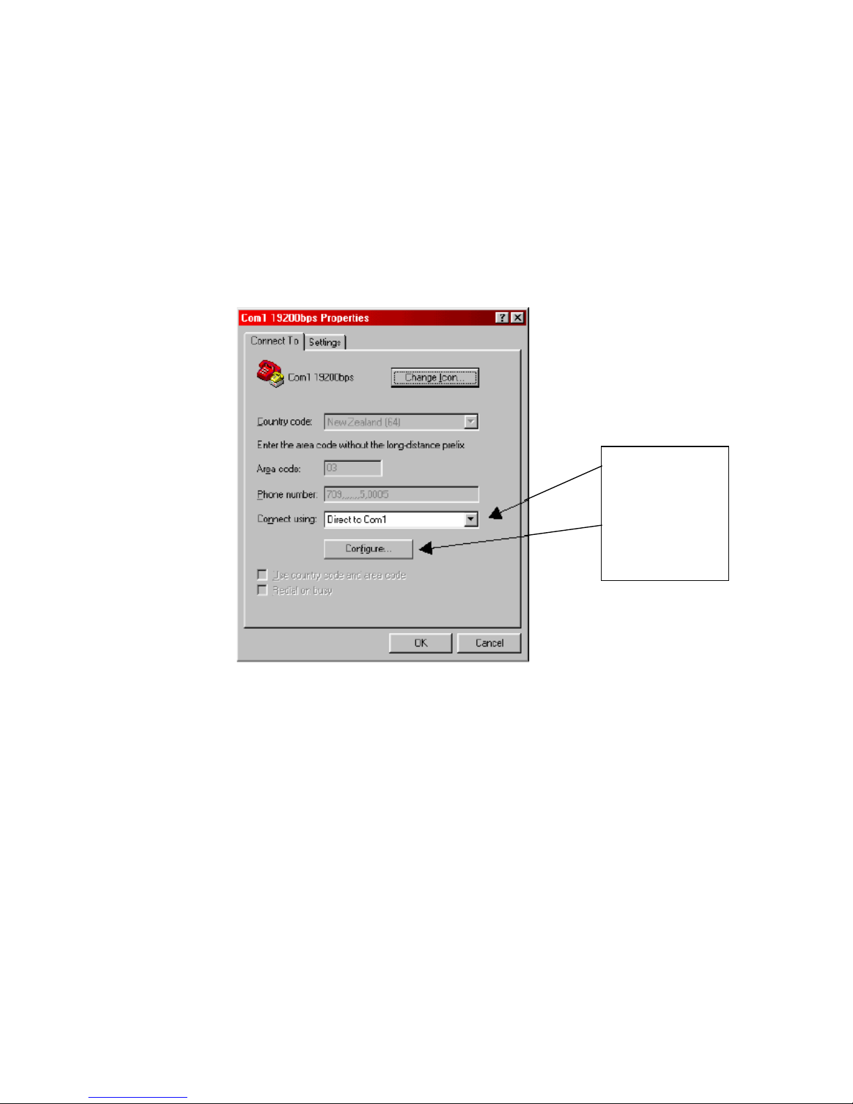
2.1 Direct RS232 Connection Configuration
This screen capture shows how Hyperterm should be configured to make a direct
connection via Com1 and RS232 lead.
This next screen capture shows the settings form for the Communications Port that is
displayed when you click on Configure. Enter all the values as they are listed here.
Use drop down
arrow to select
comm port
Use Configure
Button to get to
next screen

Date: 31/10/12 Page 6File: 700b Technical Manual ver1.9.3.docm
Hyperterm provides a facility to save connection settings to an Icon/File. Once saved the
Icon/File can be clicked to start the connection to that site name. E.g. You could save a
direct connection as “Com1 19200bps”
NOTE: The EDAC 700 RTU will not respond to Hyperterm unless it is in Program Mode.
A PIN number (default =0000) must be entered via the EDAC700 RTU keypad, after
Hyperterm is started, to put the EDAC700 RTU into Program Mode. This will allow
communications to take place.
When Hyperterm is configured correctly, and the Program Mode PIN is entered via the
EDAC 700 Keypad, you should see the above menu in the Hyperterm window.

Date: 31/10/12 Page 7File: 700b Technical Manual ver1.9.3.docm
2.2 Modem Connection Configuration
NOTE: This type of connection should only be done after experience with a direct RS232
connection
This screen capture shows how Hyperterm should be configured to make a remote
modem connection. Replace the ‘709’ number with the required phone number. The
‘….5.0005’ is required to establish a modem connection.
Making a connection
Once the connection information is configured and saved you can double click the
Icon/File and a window will open allowing you to initiate dialling to the pre-configured
site.
When a connection to the EDAC700 RTU is established via a modem connection, the
PIN to put the product into Program-Mode is not required. The EDAC700 RTU will go
into Program Mode automatically.
Date: 31/10/12 Page 8File: 700b Technical Manual ver1.9.3.docm
Com -
Output 1-20 +
Load
(relay)
Transducer
Power
Supply
-
-
+
+
Mains
supply
Max 30v @ 150mA
10 Ohms internal
resitance when on
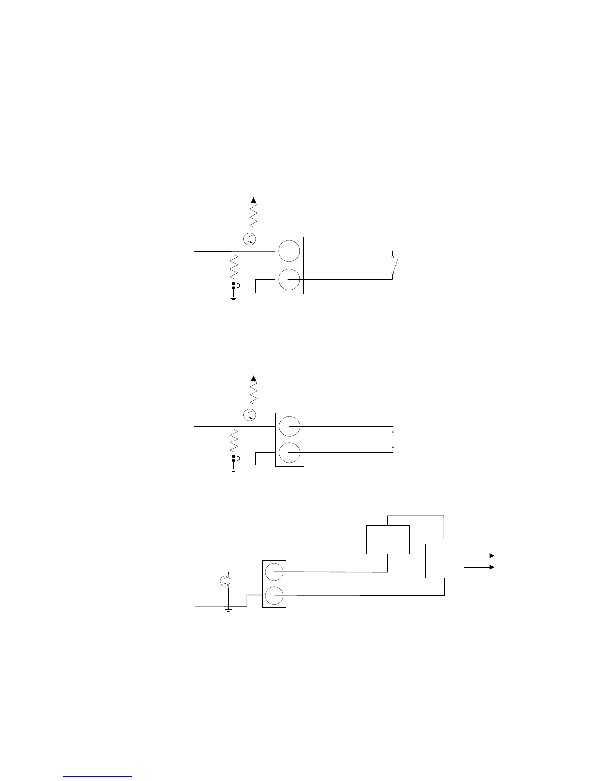
3 Physical Sensor Wiring and Measurements
The EDAC700 RTU has 20 physical input/output (I/O) terminals. The following diagrams
show how the circuits around each of the I/O terminals are configured to perform each of
the six functions.
3.1 Digital Input - Normally Open
Normally open and normally closed inputs have a 0-10V input range.
Normally Open, clean contact, input to Com/Gnd. Triggers below ~1.5V.
3.2 Digital Input – Normally Closed
Normally Closed, clean contact, input at Com/Gnd. Triggers above ~1.5V.
3.3 Digital Outputs
Open collector configuration
N.O.
Com
Input 1-20
(Normally open)
+5v
S/W ctrl
pull up
pull down
via shunt
N.C.
Com
Input 1-20
(Normally closed
)
+5v
S/W ctrl
pull up
pull down
via shunt

Date: 31/10/12 Page 9File: 700b Technical Manual ver1.9.3.docm
3.4 Analogue Inputs
0-1Vdc or 0-10Vdc transducer wiring
4-20mA Transducer, two-wire wiring
4-20mA Transducer, three-wire wiring
4-20mA Transducer, four-wire wiring
Com -
Input 1-20 +
"2 wire"
4-20mA
Transducer
Regulated
Transducer
Power
Supply
-
-
+
+
Mains
supply
Com -
Input 1-20 +
"3 wire"
4-20mA Transducer
Regulated
Transducer
Power
Supply
-
-
+
+
Mains
supply
Sig
Com -
Input 1-20 +
"4 wire"
4-20mA Transducer
Regulated
Transducer
Power
Supply
-
-
+
-+
Mains
supply
+
Com -
Input 1-20 +
Transducer
0-1Vdc or 1-10Vdc
Regulated
Transducer
Power
Supply
-
-
+
-+
Mains
supply
+

Date: 31/10/12 Page 10File: 700b Technical Manual ver1.9.3.docm
3.5 Analogue Configuration
3.5.1 Sensor Calibration
Sensors are calibrated by providing two sets of coordinates (4 values) from a graph,
from these coordinates the slope of the graph can be calculated, this is also called the
multiplier (M).
Reading in Engineering units (Y) = multiplier (M) * sensor reading in mA/Volts (X) +
offset (C )
By making fine adjustments of the set points and using an external calibration reference
we can calibrate the sensor.
3.5.2 Calibration Example 1
You may have trouble doing fine adjustment of slope, by adjusting the high or low
calibration points. The EDAC700 RTU may give you the impression that it does not use
the decimal component of the value entered, making it feel like it has quite coarse
control over calibration values. The EDAC700 RTU actually uses 5 decimal places more
than the decimal places entered in the calibration values. Therefore entering 3.12 will
cause the EDAC700 RTU to use a value of 3.1200000 and entering 3.1234 will mean
3.123400000 is used.
The formula for calibration of slope is:
mA x steps x multiplier = display value (assume offset =0) & V x steps x multi = display
value
where steps 1V = 4095, mA = 4095/20
eg at 1:1 becomes: 20mA x 4095/20 x 0.004884 = 20
To calibrate the multiplier:
1. Set up reading as desired with low/high mA and Eng units
2. Read the display. (D1) eg 19.5
3. Note the expected display (D2) eg 20.0
4. Calculate correction factor D2/D1 (20.0/19.5 = 1.025)
5. Adjust mA high value by correction factor HmA x D2/D1 (20 x 1.025 = 20.51)
6. The display should now read as expected.
C=Offset
Y=Eng Units
Hi Eng
= 100%
Low Eng
= 0%
Y = M * X + C
X = mA
Low Value
= 4mA
High Value
= 20mA

Date: 31/10/12 Page 11File: 700b Technical Manual ver1.9.3.docm
3.5.3 Calibration Example 2
This Calibration procedure is longer and more involved but does produce a more
accurate calibration.
As discussed on the pervious page, four values are required, this is illustrated in the
table below.
Volts or mA’s Engineering units
Low Point
Low mA or V Low Eng Units
High Point
High mA or V Hi Eng Units
For this example we will use a pot which will display a 0-100% range. It could be a
Transducer in a reservoir measuring the percentage full level.
Displayed Engineering Units for the example will be percent.
The pot will have a physical output range of 0-10 volts.
1. Configure Analogue Input via the Program Mode.
2. Low V value = 0
3. High V value = 10
4. Low Eng units = 0
5. High Eng units = 100
6. Decimal place spk = 1
7. Input type = D Always Report (must be set to this to do calibration, can be
changed after calibration)
8. You need to record a suitable voice recording in both the “on Voice message” and
“off voice message”. This message should be the same in both slots.
9. Go Back to Run Mode
10. Press down arrow twice to get to the Input display screen
11. Use left/right arrows to display your analogue input location
12. Set pot at lowest reading, for this example it will be 0 volts, display should read Zero
13. Using a calibrated DVM, measure the actual voltage at the input terminal and note it
down on paper
14. Set pot at highest reading, for this example it will be 10 volts, display should read
Ten, do not worry if it does not.
15. Using a calibrated DVM, measure the actual voltage at the input terminal and note it
down on paper.
16. Go back to Program Mode, and go back to configuring your analogue Input location
17. Enter the Low and High readings observed on the DVM into “Low V value” and “High
V value” , go back to Run Mode
18. Check readings on display at low and high end. Calculate the difference between
displayed reading and expected reading at each end. If the slope has been
calculated correctly, these calculated deference’s should be very similar. This is the
offset.
19. Go back to Program Mode, and back to configuring your analogue Input location
20. Enter the calculated Offset into the appropriate Offset location.
21. Go back to Run Mode and check the displayed reading for low and high end.
22. Reading should know be calibrated.
23. You can continue to adjust the Offset and Multiplier to achieve better calibration
For greater flexibility with analogue inputs please refer to notes on Input Mapping.

Date: 31/10/12 Page 12File: 700b Technical Manual ver1.9.3.docm
Analogue alarm settings
When configuring an analogue input you need to set Alarm High “Set Point”, Alarm Low
“Reset Point”, and select the “Analogue trig type”.
The “Analogue trig type” setting will decide how the analogue signal is tested against the
“Set Point” and “Reset Point”. Sensor signals out of normal operating range will
generate an Input alarm trigger to the Group.
T
A
T
T
A
T
High SP
Low SP
A
=Alarm
T=Timer Delay
Time
S
e
n
s
o
r
U
n
i
t
s
Shows the relationship between Set Point and Reset Point, and the analogue
signal.
(High SP = Set Point, Low SP = Reset Point).
The following trigger types are supported:
Trigger when high
- Trigger when the analogue signal is above the “Set point”.
- Remove the trigger when the analogue signal is below the “Reset point”.
Trigger when low
- Trigger when the analogue signal is below the “Set point”.
- Remove the trigger when the analogue signal is above the “Reset point”.
Note: The ”Set point” value must be smaller than the “Reset point”.
Outside set/reset point
- Trigger when the analogue signal is above the “Set point” or below the “Reset point”.
- Remove the trigger when the analogue signal is between the “Set point” and the “Reset
point”.
Between set/reset points
- Trigger when the analogue signal is between the “Set point” and the “Reset point”.
- Remove the trigger when the analogue signal is above the “Set point” or below the
“Reset point”.

Date: 31/10/12 Page 13File: 700b Technical Manual ver1.9.3.docm
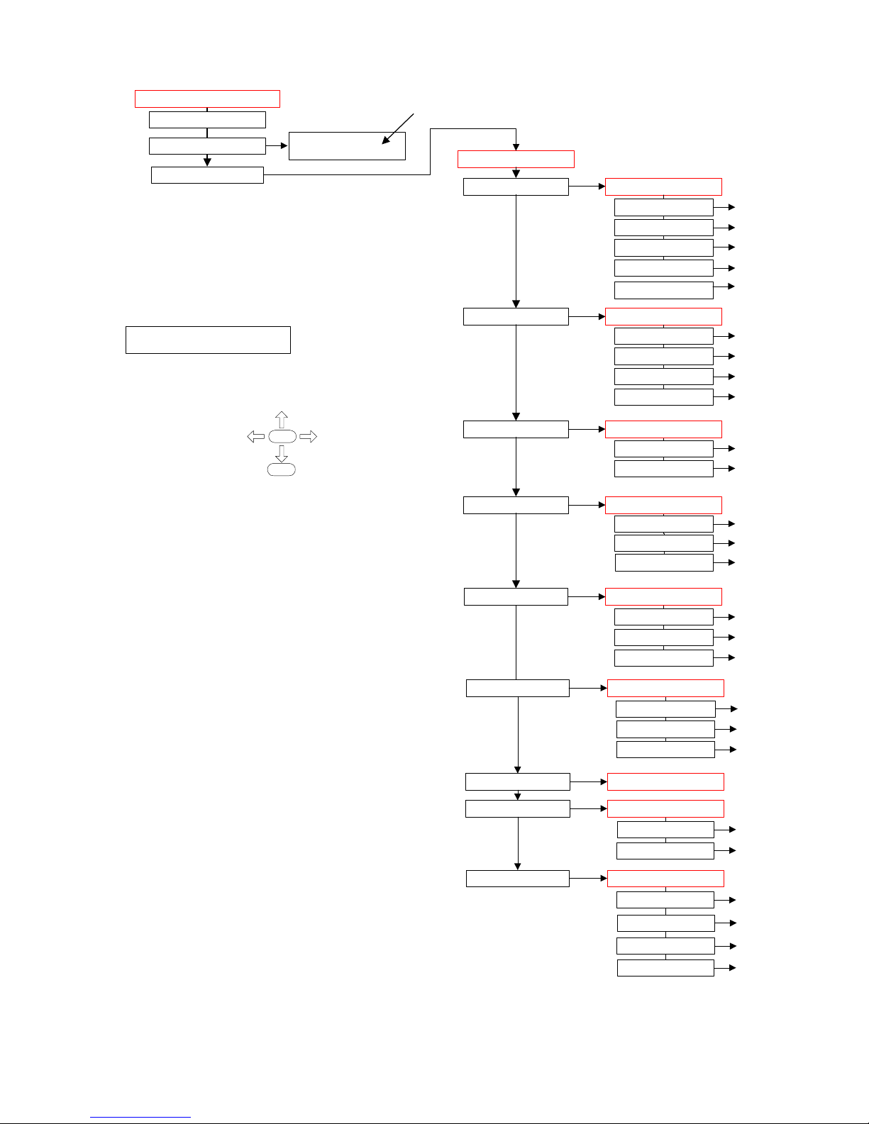
4 EDAC700 RTU Main Menu Structure
Date: 31/10/12 Page 14File: 700b Technical Manual ver1.9.3.docm
Main Menu
Exit to run mode
Change Current Roster
Configure Dialler
Configure I/O
Configure groups
Configure phone num
Configure call list
Configure rosters
Configure tap
Configure system
Configure speech
Configure misc
System msgs...
Site Message
Up/Download config
Erase config
Change Date & Time
Roster is
1 Roster 1
* = Current setting,
also indicates you are in a pick list, use up/down
arrows to move through choices. OK to select
Use Up/Down arrows to move through menu choices
Dialler Menu
I/O Menu
Roster Menu
Add a roster
Delete a roster
1 Roster 1...
TAP Menu
Add tap
Delete tap
1 3385517...
Speech Menu
rings answ norm=1
Misc Menu
Group Menu
Phone List Menu
Call List Menu
1st line on display is menu heading
2nd line is menu option
Red = Menu Heading
Add i/o
Delete i/o
253-1 RTU Batt
254-1 RTU Power
Add group
Delete group
1, Group 1
2, Group 2
Add phone number
Delete Phone number
Add a call list
Delete a call list
Call list 1...
Use: Up/Down arrow keys
& <ESC> to go back
1-1 Input 1...
RS232 config
OK
Esc

Date: 31/10/12 Page 15File: 700b Technical Manual ver1.9.3.docm
Off
Normaly Open
*Normaly Closed
20mA Loop
10V analogue
1V analogue
Output-reset off
Output-reset on
I/O Menu
Add I/O
Delete I/O
1-1Input 1
2-2 Input 1
1 Input No.=1
>_
Input name
Input 1
Input function
20mA loop
Group
*1 Group 1
Add group
*1 Group 1
Trig/dial time(s)=2
>_
Lat/dial time(s)=3
>_
Lat/untrig time(s)=1
>_
Input alarm
*do not latch
latched input
*do not latch
Input type
*trig causes dial out
report - non dial
*trig causes dial out
Low mA value = 4.00
>_
Low Eng Units value = 0
>_
High mA value = 20.00
>_
High Eng units = 100
>_
Set point=-869.61335
>_
Reset point=-869.613
>_
Analogue trig type
*trig when high
*trig when high
trig when low
outside set/reset point
betwn set/reset pts
Speak suffix mess.
* No
*No
Yes
Decimal place spoken
>_
Suffix voice message
*=play #=record
2-1 Input 1
I/O point
Group ID
Pulse Accummulator
Runtime Meter
Depending on "Input
function" selection, this
box may or may not be
present
This box has been
temporarily removed
from the menu
report-call in
always report
Offset = 0
>_
These two displays change to volts
or mA depending on "Input
Function" selected
See separate page for the
menu options relating to these
input types

Date: 31/10/12 Page 16File: 700b Technical Manual ver1.9.3.docm
pager message
Input 2
on voice message
*=play #=record
off voice message
*=play #=record
Save changes?<ok>
_
I/O Menu
*Add I/O
Delete I/O
1-1Input 1
2-1 Input 2...
Continued from previous page
Delete
1-1 Input 1
1-1 Input 1
2-1 Input 2
1 Input No.=2
_
1 Input No.=2
_
As per above Add I/O menu
As per above Add I/O menu

Date: 31/10/12 Page 17File: 700b Technical Manual ver1.9.3.docm
Save changes? <ok>
_
8 Group name
Group 8_
Grp Voice message
*=play #=record
Group pin=1000
_
Group mode
*Input
Group Menu
Add group
Delete group
1 Group 1
2 Group 2
*Input_
Output_
Delete
1 Group 1_
1 Group 1
2 Group 2
3 Group 3
Save changes? <ok>
_
2 Group name
Group 2_
Grp Voice mess. =2010
*=play #=record
Group pin=1000
_
Group mode
*Input
*Input_
Output_
2 Group name
Group 2_
As per above menu

Date: 31/10/12 Page 18File: 700b Technical Manual ver1.9.3.docm
*any key cancel
cancel not allowed
pin cancel
pager delay(sec)=15
_
Phone List Menu
Add phone number
Delete Phone number
1 RICHARD
phone name
John Smith
phone number=102
_
Cancel method
*any key cancel
Call time(s)=60
_
spk on dial-out
*No extras
Call type
*voice (eg phone)
numeric pager
*voice (eg phone)
SMS/alpha-numeric
pager
Detect tones
*dial & ring tone
Save changes? <ok>
_
report pin
*No extras
Speak Menu
report pin + menu
detect dial tone
no tone detect
detect ring tone
*dial & ring tone
Pick TAP service
* 1 3385517
*1 3385517
add TAP service
Delete
2 JOHN SMITH
1 RICHARD
2 John Smith
3 Brian Smith
2 JOHN SMITH
phone name
RICHARD
phone name
JOHN SMITH
As per above menu
As per above menu
Speaks alarm status message straight away
PIN required to get alarm status message
Speaks Menu "Press 1 for ...2 for... 3 for...etc
Speaks menu, requires PIN to get alarm status

Date: 31/10/12 Page 19File: 700b Technical Manual ver1.9.3.docm
Call List Menu
Add a call list
Delete a call list
Call list 1...
3 BRIAN SMITH
ack drops number
*No
*2 JOHN SMITH
Save changes? <ok>
_
Yes
*No
Pick phone
Add phone num.
Add phone num.
Goes to
"Add phone number"
Wait aftr call(m)=0
_
max call count=99
Delete
JOHN SMITH
JOHN SMITH
RICHARD
Delete
Call list 2
Call list 1
Call list 2
Call list 3
Call list 1
Add phone
Goes to top of above menu
Call list 1
JOHN SMITH
Call list 1
RICHARD
Call list 1
Add phone
Call list 1
Delete phone
As per above menu
As per above menu
As per above menu
Set to yes if calling a list of pepole who
need to respond. Eg a fire alarm trigger
,
notifies fire fighters. Each can
acknowledge the call and not be called
again, while they drive to the fire statio
n

Date: 31/10/12 Page 20File: 700b Technical Manual ver1.9.3.docm
Roster Menu
*Add a roster
Delete a roster
1 Roster 1...
1,Group 7
Roster name
Roster 3
Call LIst, Group
1, Group 5
Save changes? <ok>
_
1,Group 6
1,Group 5
Call List in
* Call list 1
Call list 3
Call list 1
Delete
1 Roster 1
2 Roster 2
1 Roster 1
Roster name
Roster 1
"In", call list asosiated with this group. I
f
time frames are being used there is a
second "Out" call list which is not
displayed

Date: 31/10/12 Page 21File: 700b Technical Manual ver1.9.3.docm
TAP Menu
Add tap
Delete tap
1 3385517...
Service no=3385517
_
Service id
PG1_
2 5656565
1 3385517
service p/w
_
Save changes? <ok>
_
Delete
1 3385517
Service no=3385517
_
As per above menu

Date: 31/10/12 Page 22File: 700b Technical Manual ver1.9.3.docm
System Menu
rings answ wait=4
_
rings answ norm=1
_
rings answ canc=5
_
cancel-call in
*any key
*Any key
Not Allowed
program pin=0000
_
remote prg pin=0005
_
roster pin=0002
_
modem mode pin=0004
_
group priority
*No
Yes
*No
Pin report, call in
*report pin not req.
report pin
*report pin not req.
Save changes? <ok>
_
System msgs...
Site Message
Speech Menu
Flash access r/w OS code upgrade
Set unit back to factory defaults, erase ph
numbers, groups, call lists, rousters, & voice.
Up/Down load config
Erase config
Change Date & Time
Misc Menu
dd/mm/yy hh:mm day
22/12/00 02:49 Tues
Group pin
RS232 config
RS232 Speed
*19200
Calls each group as triggered
Calls groups in priority order 1 to ...
Distributor PIN required to change
system voice messages. Used for
Languge change.

Date: 31/10/12 Page 23File: 700b Technical Manual ver1.9.3.docm
5 Detailed EDAC700 RTU Configuration
This section provides a detailed guide to every menu available on the EDAC700 RTU. It
is assumed that you are familiar with the information in the Getting Started Manual.
The entry point to each menu is described in a single line like this:
Program Mode -> Configure Dialler -> Configure I/O
This summarises the sequence of going to Program Mode by entering the correct PIN
number, then navigating to and selecting the Configure Dialler and Configure I/O menu
options.
Screen shots are included to enable you to confirm your position in the menus.
Telepermit Requirements; New Zealand
The grant of a Telepermit for any item of terminal equipment indicates only that Telecom
NZ has accepted that the item complies with the minimum conditions for connection to
its network. It indicates no endorsement of the product by Telecom, nor does it provide
any sort of warranty. Above all, it provides no assurance that any item will work correctly
in all respects with another item of Telepermitted equipment of a different make or
model, nor does it imply that any product is compatible with all of Telecom’s network
services.
This equipment shall not be set up to make automatic calls to the Telecom 111
Emergency Service.
The “max call count” parameter shall be set to a value of not more than 10.
The “wait after call (m)” parameter shall not be set to the default value of 0
Telepermitted equipment only may be connected to the auxiliary telephone port. The
auxiliary telephone port is not specifically designed for 3-wire-connected equipment. 3wire-connected equipment might not respond to incoming ringing when attached to this
port.
In the event of any problem with this device, it is to be disconnected, and a CPE item
connected to one of its terminal ports may be connected directly in its place. The user
should then arrange for the product to be repaired. Should the matter be reported to
Telecom as a wiring fault, and the fault is proven to be due to this product, a call-out
charge will be incurred.
Austel Requirements; Australia
The “max call count” parameter shall be set to a value of not more than 15

Date: 31/10/12 Page 24File: 700b Technical Manual ver1.9.3.docm
5.1 Configure I/O (I/O Menu)
All settings, calibration and voice messages relating to the sensor-input and digital
output configuration, including Pulse and Runtime Meters, are done in this menu.
5.1.1 Common Settings
Program Mode -> Configure Dialler -> Configure I/O
The “ Configure I/O ” menu includes Add & Delete I/O options, and at least three preconfigured Inputs:
253-1 RTU Batt Battery back up reading
254-1 RTU Power RTU Power supply voltage
1-1 Input 1 Example input configuration
As you define new Inputs using Add I/O, they are added to the list in this menu. You can
modify any existing entry by pressing <Ok> when its name is displayed.
The first setting displayed is the Physical I/O Point number this Input uses. This will be a
number between 1 and 20 (unless you have an expansion option). You do not have to
use consecutive numbers although it is recommended for simplicity.

Date: 31/10/12 Page 25File: 700b Technical Manual ver1.9.3.docm
The next setting is the display label for the Input or Output. The LCD accommodates 20
characters, however labels can be up to 40 characters long.
Select a descriptive name that suits the sensor type.
Once a character has been entered, the existing text will be replaced. You can now
backspace using <Left> to edit your name entry.
Note! Long names use up data base space (RAM).
The next setting is the Group to which the input sensor is assigned. Press <Down> to
see each available Group. The dialler will give a double beep on the last Group entry.
You can also add a new group from this option. Press <Up> from Group 1 to reach Add
Group, <Ok> to select.
Each I/O configuration must be associated with a Group. When an Input goes out of
range it is the Group associated with the Input that generates an alarm notification call.
The initial mapping or association of an Input with a Group is done when configuring the
Input, however the mapping can be changed at any time.
Outputs must be associated with an Output Group. Outputs cannot be in the same
Group as Inputs.
Note! An Output Group is limited to 9 outputs.
The next setting is the Input Function, which has the currently selected option showing.
Scroll through the menu options using <Up> & <Down> to choose an appropriate I/O
function, which will be one of the following:
Off
Sensor has been removed for servicing. This allows a sensor to be removed from a
configured Physical I/O Point without causing an alarm call to be initiated.
Normally Open
Clean contact NO digital input.
Normally Closed
Clean contact NC digital input.

Date: 31/10/12 Page 26File: 700b Technical Manual ver1.9.3.docm
20mA Loop
4mA to 20mA analogue input.
10V Analogue
0V to 10V DC analogue input.
1V analogue
0V to 1V DC analogue input.
Output reset off
Digital output set OFF when EDAC700 RTU is powered up or reset.
Output reset on
Digital output set ON when EDAC700 RTU is powered up or reset.
Pulse accumulator
Please contact EDAC Electronics, New Zealand for information on this optional
expansion module.
Runtime meter
Please contact EDAC Electronics, New Zealand for information on this optional
expansion module.
If you are editing an entry with an Analogue Input Function, then extra analogue settings
will be presented. Proceed through the section Analogue Settings for details on these.
If you have completed that section, or you are editing an entry with any other Input
Function, the settings continue as follows.
The next setting is the Input Alarm method, which has the currently selected option
showing.
Scroll through the menu options using <Up> & <Down> to choose an appropriate alarm
method, which will be one of the following:
Latched input
Alarm Trigger will be latched on. If the sensor goes back into range the alarm trigger
will remain present until acknowledged by a user.
do not latch (default)
The alarm trigger will be removed if the sensor goes back into range. This means the
alarm is self-cancelling.

Date: 31/10/12 Page 27File: 700b Technical Manual ver1.9.3.docm
This setting is the delay in seconds for the period the trigger must be continuously
present before being accepted as a valid alarm trigger.
Type in the delay in seconds for the period from the time a valid alarm trigger is present
to the time alarm notification calls are initiated.
Note! This menu choice will only appear if "Latched input" is selected from the "Input
alarm" menu choice.
Type in the delay in seconds for the period an analogue signal must remain in the
normal operating range before it is accepted as being back in normal operating range.
Choose when you want the value to be reported: on Dial in, Dial out or Both.
trig causes dial out (default)
The EDAC700 RTU will make alarm notification calls when this Input is triggered.
Report - non dial
Will report a status voice message whenever an alarm notification call is made.
Report – call in
A status voice message will be reported when a user calls the EDAC700 RTU.
Always Report
The EDAC700 RTU will make alarm notification calls when an Input is triggered. A
status voice message will be reported when the EDAC700 RTU makes an alarm
notification call or when a user calls the EDAC700 RTU.

Date: 31/10/12 Page 28File: 700b Technical Manual ver1.9.3.docm
Enter a suitable pager message. If an analogue sensor has been configured, a relevant
analogue reading is added to the end of the pager message at the time of transmission.
Your pager message will need to allow for this. Eg. “Water Level is high, the reading is ”.
Each I/O Sensor Configuration record can have a pager message associated with it.
Voice messages can be recorded for any input. A separate message can be recorded
for the On (alarmed) state and the Off state off the input.
If a voice message has been recorded for this input, you have the option in this setting to
play back the existing message by pressing <*>. Press <#> to start recording your On
message. Several messages are displayed while the RTU prepares to record. Wait for
the EDAC700 RTU to beep before you start your recording.
Press any key when you are finished recording. The EDAC700 RTU will play your
recording back to you. Press <Ok> to stop listening to the recording playback, then
<Ok> to move to the next setting.
This setting allows you to record an Off message. This procedure is the same as for the
On message.
Press <OK> to save and exit, or press <Esc> to discard any changes.

Date: 31/10/12 Page 29File: 700b Technical Manual ver1.9.3.docm
5.1.2 Analogue Settings
Program Mode -> Configure Dialler -> Configure I/O -> Add/Edit Input -> Input function > Analog/4-20
For more detail on these settings, refer to the Analogue Configuration section.
Enter the sensor low output value in mA.
Note! Will say “Low V value” if 0-1V or 0-10V has been selected.
Enter the sensor high output value in mA.
Enter the sensor low value in engineering units that the “Low mA value” represents
Enter the sensor high value in engineering units that the “High mA value” represents
Enter the calculated Offset in engineering units to calibrate the reading to the external
reference.
High alarm set point. Enter the signal level in engineering units that will cause a high
level alarm.

Date: 31/10/12 Page 30File: 700b Technical Manual ver1.9.3.docm
Note! For code Ver 1.2.8p and below 4 decimal points must be entered. Eg. to enter 30
you must enter 30.0000.
Low alarm set point. Enter the signal level in engineering units that will cause the alarm
condition to reset or stop triggering.
Note! For code Ver 1.2.8p and below 4 decimal points must be entered. Eg. to enter
30 you must enter 30.0000.
*Trig when high (default)
- Trigger when the analogue signal is above the “Set point”.
- Remove the trigger when the analogue signal is below the “Reset point”.
Trig when low
- Trigger when the analogue signal is below the “Set point”.
- Remove the trigger when the analogue signal is above the “Reset point”.
Note: The ”Set point” value must be smaller than the “Reset point”.
Outside set/reset point
- Trigger when the analogue signal is above the “Set point” or below the “Reset point”.
- Remove the trigger when the analogue signal is between the “Set point” and the “Reset
point”.
Between set/reset pts
- Trigger when the analogue signal is between the “Set point” and the “Reset point”.
- Remove the trigger when the analogue signal is above the “Set point” or below the
“Reset point”.
Yes
Will ask for a suffix to add to the voice message after speaking the analogue sensor
value. This would normally be the relevant engineering unit. If this is “Yes” the next
setting will prompt for the suffix voice message to be recorded.
*No (default)
Will speak the analogue value with no suffix.

Date: 31/10/12 Page 31File: 700b Technical Manual ver1.9.3.docm
Type the number of decimal places to be displayed and spoken for this analogue sensor.

Date: 31/10/12 Page 32File: 700b Technical Manual ver1.9.3.docm
5.2 Configure Groups (Group Menu)
Each configured I/O must be mapped to a Group.
It is the Group that generates the alarm notification call.
Program Mode -> Configure Dialler -> Configure Groups
The “Configure Groups” menu includes Add & Delete Group options, and at least one
pre-configured Group:
1,Group 1 Example group configuration
As you define new Inputs using Add Group, they are added to the list in this menu. You
can modify any existing entry by pressing <Ok> when its name is displayed.
The next setting is the display label for the Group. The LCD accommodates 20
characters, however labels can be up to 40 characters long.
Select a descriptive name that suits the group type.
Once a character has been entered, the existing text will be replaced. You can now
backspace using <Left> to edit your name entry.
When working with different Input sensor types it is logical to group the sensor types
together. E.g. Intruder Sensor Group, Smoke detector Group. These groups can then
be associated with a Call List with the telephone numbers of the appropriate personnel.
The next setting allows you to record a voice message to suit the group name. E.g.
“Group 1” or “Smoke Detectors”.
Several messages are displayed while the RTU prepares to record. Wait for the
EDAC700 RTU to beep before you start your recording.

Date: 31/10/12 Page 33File: 700b Technical Manual ver1.9.3.docm
Press any key when you are finished recording. The EDAC700 RTU will play your
recording back to you. Press <Ok> to stop listening to the recording playback, then
<Ok> to move to the next setting.
Enter a Group PIN. Each Group has a 4-digit PIN number associated with it. On an
alarm notification call the number is entered using a touch-tone phone to acknowledge
and cancel the alarm. A single PIN can be used for all Groups or each Group can have
its own individual PIN.
This setting allows you to choose either an Input (Default) or an Output Group type. You
cannot map Inputs and Outputs to the same Group. In order to turn an Output on it must
be associated with an Output Group.
Output Groups are limited to 9 Outputs. The number of keys available on a normal
touch-tone phone determines this. The keys, numbers 1 to 9, are used to toggle the
outputs on and off during a phone call with the EDAC700 RTU.
Press <OK> to save and exit, or press <Esc> to discard any changes.

Date: 31/10/12 Page 34File: 700b Technical Manual ver1.9.3.docm
5.3 Configure Phone Numbers (Phone List Menu)
The EDAC700 RTU requires a phone book, called the Master Phone List in order to
build a Call List. All I/O notification must be mapped to a Call List. The Call List and the
Master Phone List each only require a single entry in order to make successful alarm
notification calls.
Program Mode -> Configure Dialler -> Configure Phone num
The “Configure Phone num” menu includes Add & Delete Phone Number options.
As you define new Numbers using Add Phone Number, they are added to the list in this
menu. You can modify any existing entry by pressing <Ok> when its name is displayed.
The next setting is the display label for the Phone Number. The LCD accommodates 20
characters, however labels can be up to 40 characters long.
Enter a suitable name for the contact person or service associated with the number.
The EDAC700 RTU keypad will allow you to enter a name using the alphanumeric
function of the keypad. It is similar to editing a cell-phone phone book entry.
You can now enter a phone number. Do not forget any prefix that may be required to
get an outside line, or any required area codes. Use a comma to put in a delay. On an
EDAC700 RTU Keypad <*> is read as a comma when entering phone numbers.
Choose an alarm cancellation method from these options:
cancel not allowed
The EDAC700 RTU will play the appropriate voice messages for the configured time (set
in this menu) and then hang up.
any key cancel
The EDAC700 RTU will stop making any further alarm notification calls if any key on a
touch-tone phone is pressed.

Date: 31/10/12 Page 35File: 700b Technical Manual ver1.9.3.docm
PIN cancel
A valid PIN number for the triggered Group must be entered. The PIN required is
configured in the Group Menu. This option would normally be used when other people
might answer the phone that the EDAC700 RTU calls.
This setting is used to set the time the EDAC700 RTU is allowed on an alarm notification
call for this group. It is the time from the instant the I/O trigger causes dial-out to the
time it will hang up if no DTMF tone is received. If it takes a while for the exchange to
connect or there is a long delay before the phone is answered, then this time needs to
be increased. The time is entered in seconds.
Choose a dial out speech method. When the EDAC700 RTU makes an alarm
notification call you can set one of four options to determine the method of presenting
voice messages.
No extras
Will start speaking alarm status message straight away, the user can then press a key or
enter a PIN to acknowledge and cancel the alarm.
Report pin
Will ask for a PIN before it starts speaking the alarm status message. Any valid Group
PIN will work.
Speak Menu
Will start by speaking the Main Menu “Press 1 for….2 for…3 for…etc. Will not require a
PIN after pressing 1 to get the alarm status message.
Report PIN + Menu
Will start speaking the main menu but will ask for a PIN after pressing 1 to get the alarm
status message. Any valid Group PIN will work.
This sets the type of response to an alarm call used on this number.
Voice
A voice message will be spoken to a human recipient on a phone.

Date: 31/10/12 Page 36File: 700b Technical Manual ver1.9.3.docm
Numeric pager
A numeric message will be sent to a numeric pager.
Note! If the Numeric pager option is chosen the dialler will ask you to enter a pager
delay.
SMS/alpha-numeric pager
A text message will be sent to an alphanumeric pager or a cell phone.
Note! If the SMS/alpha-numeric pager option is chosen the dialler will ask you to
choose a pre-configured TAP service - see Configure TAP for more detail.
The EDAC700 RTU is capable of detecting dial tone and ring tone from the telephone
exchange using its inbuilt modem.
If the EDAC700 RTU will not dial, due to being unable to detect dial tone you can set it to
“no tone detect”. This is also called “blind dialling”. This will allow the EDAC700 RTU
to initiate a call regardless of the dial tone frequency.
no tone detect (default)
The dialler will dial without waiting to detect dial tone.
detect dial tone
The dialler will only dial after dial tone is detected. NOTE: Dial tone detect is not
available in Australia
detect ring tone
This feature is not currently available. Please contact EDAC Electronics, New Zealand
with any queries.
dial & ring tone
This feature is not currently available. Please contact EDAC Electronics, New Zealand
with any queries.
Press <OK> to save and exit, or press <Esc> to discard any changes.

Date: 31/10/12 Page 37File: 700b Technical Manual ver1.9.3.docm
5.4 Configure Call List (Call List Menu)
The EDAC700 RTU must have a Call List defined before it can make alarm notification
calls. The Call List and Master Phone List only require one entry each in order to make
successful calls.
When building a Call List you must first select a phone number to call. If none are
defined the EDAC700 RTU will let you define them as required from within the “Call List
Menu”.
Program Mode -> Configure Dialler -> Configure Call List
The “Call List” menu includes Add & Delete call list options.
As you define new Call Lists using Add a call list, they are added to the list in this menu.
You can modify any existing entry by pressing <Ok> when its number is displayed.
Select a phone number by scrolling through the numbers using <Up> & <Down>. The
dialler will give a double beep on the last number entry. You can also add a new
number from this option. Press <Up> from the first number listed to reach “Add phone
num”.
This setting is a delay in minutes that the EDAC700 RTU will wait between calls from the
Call List. This is used to allow a user to phone in and cancel the alarm if required. It
also allows the EDAC700 RTU time to self-cancel if the alarm trigger has been removed
or gone back into its normal operating range.
This setting must be set if a pager is being called or text messaging to a cell phone are
being used.
New Zealand setup;
The “wait after call (m)” parameter shall not be set to the default value of 0.
When the EDAC700 RTU dials a number from the Call List it looks for an acknowledge
signal from the user. When set to "Yes" the EDAC700 RTU, after receiving the

Date: 31/10/12 Page 38File: 700b Technical Manual ver1.9.3.docm
acknowledge signal from the user, will drop the phone number it is currently dialling from
the list.
You can set the maximum number of calls for each number on the Call List.
New Zealand Setup;
The “max call count” parameter shall be set to a value of not more than 10.
Australian Setup;
The “max call count” parameter shall be set to a value of not more than 15
Press <OK> to save and exit, or press <Esc> to discard any changes.

Date: 31/10/12 Page 39File: 700b Technical Manual ver1.9.3.docm
5.5 Configure Rosters (Roster Menu)
If no Rosters are defined the EDAC700 RTU will default to using Call List 1. A Roster
must have at least one Call List or a number of Call Lists mapped to it. Once one or
more Rosters have been configured the operator can change the current Roster either
via the menu options using a touch-tone phone or the EDAC700 RTU keypad.
Program Mode -> Configure Dialler -> Configure Rosters
The “Roster” menu includes Add & Delete roster options.
As you define new Rosters using Add a roster, they are added to the list in this menu.
You can modify any existing entry by pressing <Ok> when its name is displayed.
You can give the roster a meaningful name, or leave the default name.
This setting links a Call List to this roster. The display is indicating that Call List 1 is
connected to Group 1, so if Group 1 is triggered it will use Call List 1 to make alarm
notification calls from.
Use the arrow keys to scroll through the list. The dialler will give a double beep on the
last Call List entry.
The next setting determines which Call List is used during the default time frame.
Press <OK> to save and exit, or press <Esc> to discard any changes.

Date: 31/10/12 Page 40File: 700b Technical Manual ver1.9.3.docm
5.6 Configure TAP (TAP Menu)
The Tap service is configured via this menu. See the TAP Configuration section for the
required service and equipment details.
Program Mode -> Configure Dialler -> Configure Tap
The “TAP” menu includes Add & Delete tap options.
As you define new Tap definitions using Add tap, they are added to the list in this menu.
You can modify any existing entry by pressing <Ok> when its number is displayed.
This is the access number to connect to the TAP service. Enter the appropriate number
for your telecom provider.
This entry is also provider specific. Enter the correct code for your location.
Enter the access password, if one is required.
Press <OK> to save and exit, or press <Esc> to discard any changes.
Please contact your local dealer, or EDAC Electronics, New Zealand if you have any
further queries on this section.

Date: 31/10/12 Page 41File: 700b Technical Manual ver1.9.3.docm
5.7 Configure System Settings
This Menu is where the user can setup default values for security and operational
options of the dialler.
Program Mode -> Configure Dialler -> Configure System
This sets the number of telephone rings the EDAC700 RTU will count before answering
an incoming call when in the Normal state.
This sets the number of telephone rings the EDAC700 RTU will count before answering
an incoming call in the Wait state. This is when the dialler is in Run mode and there are
alarms triggered.
This sets the number of telephone rings the EDAC700 RTU will count before answering
an incoming call when cancelled alarms exist.
This sets the method for cancelling an alarm when answering an incoming call.
Not allowed
*Any key (default)
Group Pin
This sets the security number (PIN) used to access Program Mode from Run mode.

Date: 31/10/12 Page 42File: 700b Technical Manual ver1.9.3.docm
This sets the security number (PIN) used to access the Roster Menu over a phone call,
i.e. menu option ‘2’ on the Spoken Menu.
This sets the security number (PIN) used to establish a remote modem connection. This
function is used to talk to an external device attached to the RS232 port of the EDAC700
RTU.
Example: Remote command; “ATDT <PHNUMBER> , , , , , , 4, , 0004”
Modems do not all wait the same time for a ‘,’. The user may have to experiment to
achieve the desired result.
This sets the security number (PIN) used to establish a remote modem connection in
Program Mode. This allows the user to remotely setup the EDAC700 RTU as if it was
connected directly to the local RS232 port.
Example: Remote command; “ATDT <PHNUMBER>, , , , , , , 5, , 0005”
This sets the sequence of alarm notification calls made when multiple Groups have
triggered alarms.
No (default)
When set to “No” the EDAC700 RTU will make alarm notification calls alternatively from
each triggered Group.
Yes
When set to “Yes” the EDAC700 RTU will consider the lowest numbered group (Group
1) to have the highest priority. It will always dial the lowest triggered Group number, and
will keep dialling the same Group until acknowledged. It will then dial the next lowest
group.
Note! When using “Group Priority = Yes”, the EDAC700 RTU must be set up so that
Group 1 has the highest priority alarms wired into it, then Group 2, Group 3 etc.

Date: 31/10/12 Page 43File: 700b Technical Manual ver1.9.3.docm
Note! The EDAC700 RTU will not make any calls while in the Wait state, which
happens between alarm notification calls. If Group Priority = Yes and a second lower
priority group is triggered no alarm notification calls will be made for this second Group
until the first group is acknowledged.
This option is used in the Spoken Menu. When a user dials the EDAC700 RTU and this
option is set to “report pin”, menu option ‘1’ will require a PIN. If this option is set to
“report pin not req”, the user will not have to enter a PIN.
Menu option ‘1’ speaks the status of reporting inputs.
Press <OK> to save and exit, or press <Esc> to discard any changes.
Date: 31/10/12 Page 44File: 700b Technical Manual ver1.9.3.docm
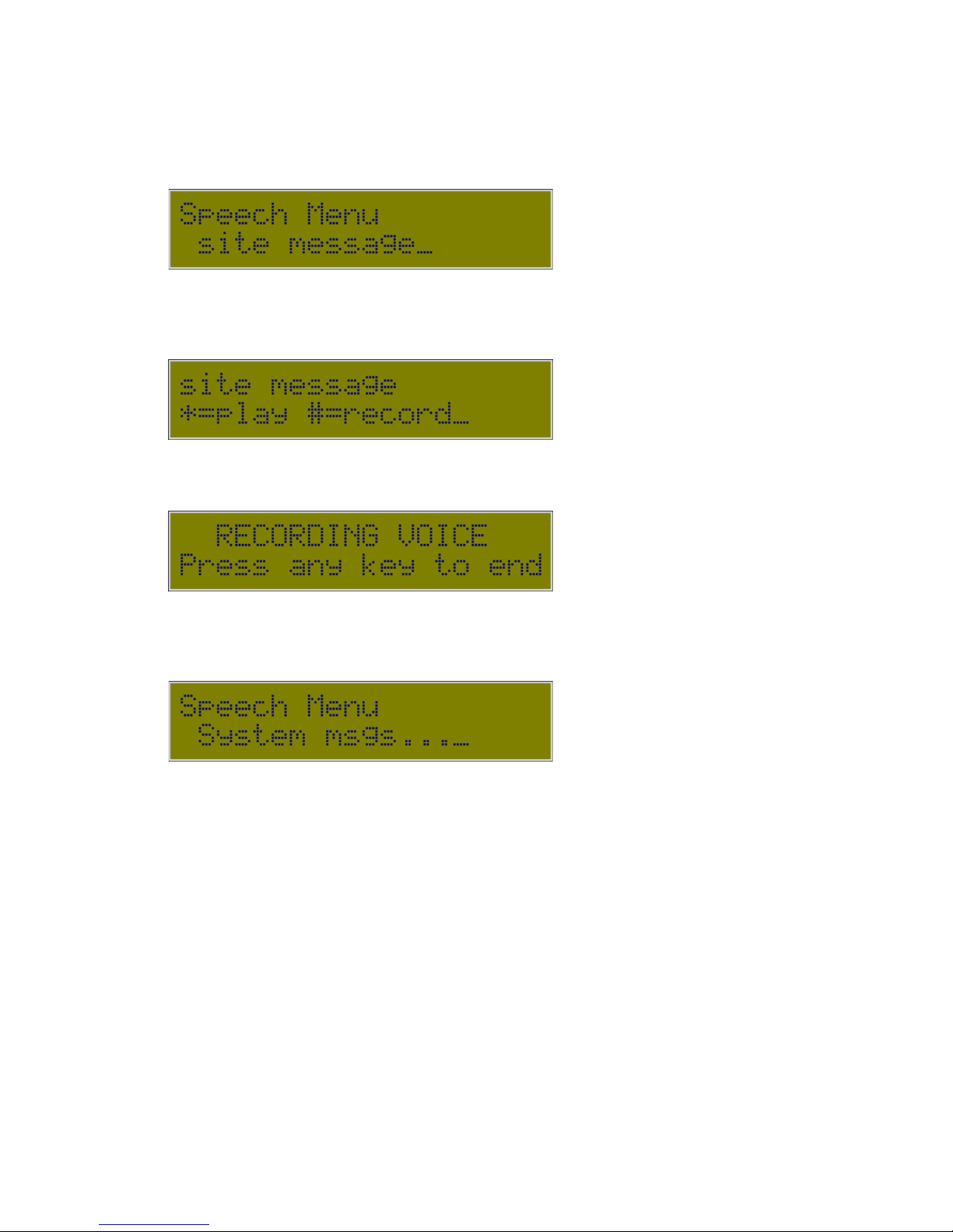
5.8 Configure Speech (Speech Menu)
This Menu lets the user configure the default speech records for the EDAC700 RTU.
Program Mode -> Configure Dialler -> Configure Speech
Selecting this option allows the user to listen to the site message (if it exists) or record
the site message. The site message usually contains the company name or the site
location.
Several messages are displayed while the RTU prepares to record. Wait for the
EDAC700 RTU to beep before you start your recording.
Press any key when you are finished recording. The EDAC700 RTU will play your
recording back to you. Press <Ok> to stop listening to the recording playback, then
<Ok> to move to the next setting.
Note! A System PIN protects selection of this option. This is only available to EDAC
Accredited Service Centres. Please contact your local EDAC representative for further
information.

Date: 31/10/12 Page 45File: 700b Technical Manual ver1.9.3.docm
5.9 Configure Miscellaneous (Misc Menu)
This menu allows the user to setup other miscellaneous options of the dialler.
Program Mode -> Configure Dialler -> Configure Misc.
Select to change the date and time.
The default time is displayed on the second line until a number key is pressed and a
change is initiated. The digits all need to be entered, but the delimiters (the “/” and “:”)
do not.
The day is edited by entering a number as shown below:
0:Sun 1:Mon 2:Tue 3:Wed 4:Thu 5:Fri 6:Sat 7:Sun
Press <Ok> to save, or <Esc> to discard any changes.
This option allows selection of the RS232 speed of the EDAC700 RTU serial port. This
must be one of:
19200, 9600, 4800, 2400, 1200 or 300 baud
Press <Ok> to save, or <Esc> to discard changes.
Note!
This setting controls the method for reloading the RTU firmware. This option is
only available to EDAC Accredited Service Centres. Please contact your local EDAC
representative for further information.

Date: 31/10/12 Page 46File: 700b Technical Manual ver1.9.3.docm
Use this option to clear all site-specific configuration.
WARNING! This option will delete ALL database records and voice files (not including
system messages).
Use this option for checking the status of user memory. Select from either Database
Usage or Voice File Usage using <Up> & <Down>, then press <Ok>.
Database Usage
This option will display the percentage used of the Database and draw a simple bar
graph representation of the database usage. If the size exceeds 95% a warning
message is displayed.
Voice File Usage
This option will display the same usage graph as the Database usage, except it shows
the percentage of the Voice Message File usage.
Note! Deleting Voice files will not create more room in the database and visa versa.
The database and the voice file area are totally independent!

Date: 31/10/12 Page 47File: 700b Technical Manual ver1.9.3.docm
6 Outputs active when Alarm triggered
When an Input is triggered and goes into an Alarm state, it is possible to configure the dialler so
that it switches an Output. This output could be connected to a siren or flashing light. Or if a 420mA sensor is used on a reservoir it could be used to turn a pump on and off.
The Output will stay on until the Alarm condition is Acknowledged, or alternatively if the Input
trigger is removed or goes back to its normal operating state the Alarm condition will self clear,
and the Output will be turned off.
Step 1. Go to Program Mode.
Step 2. Configure an Input or Inputs, mapped to Group 1 (default) or what ever number you would
like to use. Via the EDAC 700 menus you can configure an alternative Group when you are
mapping the Input to a Group.
Step 3. Configure an Output or Outputs, and map them to the SAME Input Group as that which
has been configured above. Ie the Output does not get mapped to an Output Group it gets
mapped to an Input Group.
Step 4. Program Phone numbers and call lists
Step 5. Go to Run-Mode and test.
7 Mapping Multiple Inputs to One physical Input
In some cases it can become necessary to be able to provide an ability to generate an alarm from
an input, but also get a status reading relating to that input. This applies more to analogue Inputs
than digital.
To do this we must configure two inputs, but have them both mapped to the same physical input
terminal.
For example we have a analogue 4-20mA pressure transducer measuring reservoir level. We
require a low level alarm, a high level alarm, and the ability to establish what the current level is at
any time by ringing into the product and hearing a spoken level reading.
1. Configure Analogue Input, set up so it is reporting only, option “D always report”, in “Input
Type”
2. Configure new Analogue Input, use the same Input No as used above, use calibration values
from above. Set this one to “Analogue trig type: outside set/reset point”.
This will now provide a solution that when the product is rung or rings out with an alarm, it will
always report the current reservoir level.
When the reservoir goes above or below the Set point or Reset point an alarm will be generated.

Date: 31/10/12 Page 48File: 700b Technical Manual ver1.9.3.docm
8 TAP Configuration
In order to use Alpha paging or SMS you must arrange access to a TAP server/host.
The EDAC700 RTU uses standard TAP protocol; it does not use ETAP or Pacnet.
If you are going to use SMS messaging to a cell phone, you may also need to subscribe
to an additional service. In New Zealand for Telecom or 025 cell phones, this is called
"Mobile Note". This service enables the individual cell phone to receive SMS text
messages from the TAP host.
If you are in New Zealand and have a GSM or 021 cell phone you need to talk to the
manufacturer for up to date information on where to go to arrange access to a TAP host.
To configure the dialler for Paging or SMS, you must configure the TAP access numbers
and the Pager number or cell phone number.
The Tap service is configured via the “Configure TAP” menu. The table below gives
the information required for use in New Zealand.
Service Type Service No Service ID Service PW Service Speed
Alpha Paging 026,4001283 PG1 14400
Mobile Note (025) 026,199999 PG1 zmnote 14400
Vodaphone (021)
If using a pager you will need its RIC code. It is the number you dial via a normal phone
to activate the pager. This is normally located on the back of the pager, however your
service provider should have provided this number when you signed up.
The next step after configuring the TAP access is to configure your phone numbers for
notification on the Alpha/ numeric pager or cell phone.
In the “Configure phone num” menu, you should enter a suitable name, and the
access number. If using a pager, enter the RIC code. In New Zealand this will start 026.
If you are using SMS, you will enter your cell phone number here. The following table
provides the information required for use in New Zealand with Telecom 025 cell phones.
Cell phones starting with Enter as is, do not enter the 025
027…. Enter as is, including the 027
025…Plus 7 digit number 5301… then drop the 1st digit of 7 digit number
025…Plus 6 digit number 5300…then all the 6 digit number
After entering the phone number work your way down the menu and select the
“SMS/alpha-numeric pager” option. If you have not previously set up your TAP host you
will be given an opportunity to do so here. If you have, you can select the TAP service
you have previously set up.
The pager message comes from the Input configuration. See “I/O Menu” and select the
Input sensor that you want to generate paging messages.
If the input selected is configured for analogue, the analogue reading will be added to
the end of the text message entered above.
When configuring a pager notification or SMS text message a delay must be set
between each call. This is to allow the user to call into the EDAC700 RTU to
cancel/Acknowledge the alarm. It also allows the EDAC700 RTU to check if the input

Date: 31/10/12 Page 49File: 700b Technical Manual ver1.9.3.docm
trigger has been removed or gone away, and then self cancel. This delay can be
configured via the “Configure Call list” menu, option “Wait aftr call(m)=0”.
When receiving an Alpha paging message, some pagers will not display a second
notification if they receive the same message string more than once. This will give the
impression that paging is not working reliably. In order to get around this, you should
delete the pager message from the pager shortly after receiving it. This will allow it to
display a second notification from the same group or trigger.
Please contact your dealer if you require local TAP settings, or contact EDAC
Electronics, New Zealand if you have any other queries regarding this section.

Date: 31/10/12 Page 50File: 700b Technical Manual ver1.9.3.docm
APPENDIX 1
Technical Specifications
Electrical
Input Voltage: 10VDC to 30VDC
Power Supply cut off voltage, switches to battery at: 9.3v
Input Current: 300mA normal operation, with battery connected
Battery Backup: 12V 7A/Hour battery capable of over 24 hours normal operation
Battery charge current: 50mA
Auto power down at: 10.8v, protects battery from full discharge
Configurable Input/Output - Alarm, Monitor and Control
− 20 physical I/O configurable as digital or analogue input or digital output
− 2 messages per physical I/O
− Configurable as "report only" or "alarm notification".
Digital Inputs
Up to twenty digital inputs
− Normally Open Contact
− Normally Closed Contact
− +30VDC maximum
− +1.5VDC trigger
Analogue Inputs
Up to twenty 12 bit analogue inputs configurable for either
− 0V to 1V
− 0V to 10V
− 4 mA to 20mA
Outputs
Up to twenty controlling digital outputs
− Open collector
− 150mA maximum current
Zener diode protected inputs up to 24VDC.
Inputs also reverse polarity and over Voltage protected by crowbar diode.
Communication
2 line 20 digit LCD display
18 key splash-proof keypad
RS232 port
Internal 14k4 modem, with PSTN Line Interface - standard RJ45 connectors
All functions are programmed using the keypad and LCD display, the RS232 port or
via the modem.
Mechanical
Weight: 10 kg
Height: 303 mm
Width: 343 mm
Depth: 120 mm
Voice and Pager Messages

Date: 31/10/12 Page 51File: 700b Technical Manual ver1.9.3.docm
Up to 300 seconds of System and User Recordable Voice Messages
20 second voice messages per input and group (default 20 seconds can be
extended)
40 digit alpha-numeric or numeric pager message per input or group
Groups
1 to 20 inputs per group
1 to 9 outputs per group
1 group name message per group
groups can be either input or output but not both
Call Lists
1 to 20 telephone numbers per call list
Time Frames
choice of timeframe (day/night)
Rosters
unlimited rosters
only one active roster at a time
Programmable Parameters
Up to 20 telephone or pager numbers per call list.
One alphanumeric pager and SMS message per physical input and I/O group.
Up to 40 digits for telephone or pager number.
Reporting and System Messages
4 digit security PIN numbers
Groups, Call Lists, Rosters, Time Frames
Optional Expansion Unit
The 32-bit Pulse/RunMeter Unit is an optional extra for the EDAC 700. This unit features
8 Pulse Accumulator Inputs and 8 Run-Time Meter Inputs or alternatively an additional
20 digital Inputs.
The unit fits inside the EDAC 700 Case and derives its power supply from the EDAC
700.
When configured for Pulse/RunMeter Inputs it will give reports, but will not generate
alarms.
When configured as Digital Inputs, the EDAC 700 will generate alarm notification calls
Input Voltage Range: 0-20V
Input Trigger Voltage: 0V
Power Supply: 12V (derived from the EDAC 700)
Current Consumption: 30mA
8 Pulse Accumulator Inputs:
− Input Frequency: 5kHz
− Maximum Count: 4294967296
8 Run-Time Meter Inputs:
− Resolution: 0.1 Hour

Date: 31/10/12 Page 52File: 700b Technical Manual ver1.9.3.docm
Lightning Protection
The EDAC 700 RTU must be provided with an earth discharge circuit to allow for
lightning and mains surge discharge.
This can be accomplished by connecting a cable with a M3 crimp terminal attached, to
the M3 mounting screw located beside the RJ45 PHONE socket, at the bottom left
corner of the main EDAC 700 PCB. This cable should then be connected back to a
suitable earth point. This would normally be the common earth buzz bar at the
switchboard, or an external earth stake, located beside the building.

Date: 31/10/12 Page 53File: 700b Technical Manual ver1.9.3.docm
Installation Template
700 PCB
Line Phone
Com
+15
123
4
5678 910
Com
Com
Com
1112 13
14
15
16 17 1819 20
Com
Com
Com
+12v 6AH
Battery
1" Cable entry holes
Decal
25 295
15
266
303
343
10
R 3
R 6

Date: 31/10/12 Page 54File: 700b Technical Manual ver1.9.3.docm
APPENDIX 2
Frequently Asked Questions (FAQ)
EDAC700 RTU beeps intermittently and asks for a PIN number
Normally this means an alarm trigger is present and the dialler is not fully
configured.
A valid phone number, and “Call List”, must be present before the EDAC700
RTU can generate an alarm notification call successfully.
It may be trying to generate a battery or power fail alarm. Ensure the battery is
connected and the power supply is connected and working. You will need to
enter a PIN to cancel the alarm, or go to Program-Mode and back.
PIN not working
If the PIN will not work or you forget your PIN you can momentarily press the reset
button located in the top right corner of the main board and continuously hold
down a key on the EDAC700 RTU keypad while the EDAC700 RTU re-boots. It
will start in Program Mode. You can then go to the “Configure System” menu to
check or change PIN numbers if required.
Hang up with “**” not always working
When the dialler is speaking it cannot always hang up when you use “**”. This
works best when the dialler is speaking the “site message”. It will not work if it is
speaking “reporting only” inputs or acknowledged inputs. Wait for the “site
message” to start speaking again, then enter “**”, or else simply hang up. The
EDAC700 RTU will hang up the phone after a preset time-out period.
“#” re-start speech, not always working
In an alarm notification call, “#” should make speech restart from “site message”.
This does not work all the time. Works fine for call-in, when in “spoken menu”
part.
No positive “beep, beep” response for Pin number entry
In some places this positive feed back may not happen, will give one beep for
correct PIN or no beep. The voice message that follows from a correct pin will
reflect that the pin has been accepted.
Message “Invalid Option” spoken when in Rosters or Outputs
This message is normally played if you select a key press that is not going to do
any thing or is a wrong key. It also can be heard if you select “2” for Rosters or “3”
for Outputs, if no rosters or “Outputs have been defined. This will happen after
entering the PIN. Because there are no rosters defined or Outputs configured, the
EDAC700 RTU will report the pin as an “invalid Option” this is because it does not
have configuration associated with the option you have selected.

Date: 31/10/12 Page 55File: 700b Technical Manual ver1.9.3.docm
Problems with entering PIN Numbers
This problem is with “Cancel by PIN number”, not “Cancel by any key”. “Cancel
by any key” will work fine if the rules outlined below are observed.
With one Group configured, the user can enter a PIN at any time, like after the
active input message. There is no problem with this set up.
When we have multiple groups, triggered at the same time, and one call list, it
can be difficult to get a PIN accepted if it is not entered at the correct time. This
is due to each group potentially having different PIN numbers, and the correct
PIN must be entered while the EDAC700 RTU is speaking the appropriate Group
message or active input message.
With multi groups you can only enter your PIN number while the appropriate
group message, or the active input message for that group is being spoken.
It is logical to want to enter a PIN after hearing the group and active input
message. This cannot be done, as the window for the correct pin has closed. The
EDAC700 RTU will now be speaking the next group message and active input
messages.
This could be problematic, with some users. The user needs to wait until the
message replays from the start and enter the PIN during the group message.
The first digit of the pin should be held down slightly longer, this allows the
EDAC700 to hear the key press and pause the speech while the user enters the
rest of their PIN number.
This problem will only show up under quite specific conditions when two or more
groups get triggers and are connected to one call list and PIN numbers are being
used rather than “cancel by any key”.
This PIN problem could possibly make for problems with training end users. We
do not think it is acceptable to try and train operators to enter PIN numbers at
exactly the correct time. You should be able to enter any group PIN at any time
and have it applied to the correct group.
This problem will be fixed as a high priority in an upgrade that will be available in
the near future.
I cannot dial in to cancel an alarm when notified by Alpha Paging/SMS text
messaging & it also does not self-cancel when the trigger is removed
When doing paging or SMS, if the wait time is zero (default) the EDAC700 RTU
will not update input status between calls, while in the wait state, which happens
between alarm notification calls.
If the Input trigger clears itself, it may take several calls before the EDAC700
RTU stops making alarm notification calls. You need to set the wait time between
calls to 1 minute.
The wait time is in “Call List” configuration. If it is not set to 1 minute or more the
user cannot ring into the EDAC700 RTU to cancel the alarm.

Date: 31/10/12 Page 56File: 700b Technical Manual ver1.9.3.docm
The Alpha paging or SMS message has a number after the text, what is it?
If you have configured an analogue input, and when it is triggered it reports to a
pager or cell phone text message then the current analogue reading is added to
the end of the message. Your pager message needs to reflect that this reading will
be added on.
Example: Use pager messaging entry like this “High WL Alarm, the reading is: ”
On alarm notification call the text message might be “High WL Alarm, the reading
is: 12.3”.
Data Base Repair “ERROR: db repair” what does this mean?
Due to the EDAC700 RTU being a computer-based product, it is possible for it to
occasionally get its memory scrambled. If this should happen it will report that the
database has been repaired while re-booting. In most cases the EDAC700 RTU
will be fine, however you should consider using the “Erase Config” option from the
“Configure misc” menu if this should happen. If you don’t use this option you
should test that your configuration is working correctly.
You should also use “Erase Config” after an Operating System upgrade, to ensure
that all parameters line up correctly.

Date: 31/10/12 Page 57File: 700b Technical Manual ver1.9.3.docm
APPENDIX 3 - GLOSSARY
Acknowledged: When an Input has triggered an alarm, the dialler has made an alarm
notification call, and the operator has indicated to the dialler that the alarm has been
received, then the alarm is acknowledged. This means the dialler can cancel any further
alarm notification calls.
Alarm Notification Call: When the dialler makes an outgoing call, and uses its
recorded voice and pager messages to notify the called party that there are one or more
triggered alarms.
Application Voice Messages: Short messages recorded for each I/O point and Group
giving site-specific labels.
Armed: Dialler is in Run Mode and monitoring its I/O. See Normal State.
Cancelled: See Acknowledged.
Com/Gnd: Common or Ground electrical connection.
Call Lists: Selections of one or more of the numbers stored in the Master Phone List.
Each List is mapped to an input Group being monitored for alarms. If an alarm is
triggered, the RTU will use the Call List to make alarm notification calls in the order
listed. There can be a number of Call Lists constructed to accommodate different
requirements.
Default Pin Number: The factory default PIN number for access to Program Mode is
0000.
Dialler: EDAC700 RTU.
Database: The memory area where all the site-specific configuration information for the
dialler is stored. This includes Input, Group, Call List, and Roster configurations as well
as Phone numbers and security settings such as PIN numbers.
Groups: A collection of Inputs is mapped to a Group. Groups can be either one input or
any number of inputs or I/O points. These Groups can be used to trigger an alarm.
Multiple Groups can map and re-use I/O points. If an “Input” is triggered or out of range
the group it is mapped to generates an alarm. You cancel a Group rather than an input.
Input: Input signal for alarm testing or reporting. Can be configured in a number of
different ways.
I/O: Abbreviation of Input/Output. This refers in this manual to an individual dialler
screw terminal. Each terminal can be configured as either an Input or an Output.
Master Phone List: All telephone numbers and the associated names are entered into
the Master Phone List. When constructing a Call List the numbers must already have
been entered into the Master Phone List.
NO: Normally Open Input.
NC: Normally Closed Input.

Date: 31/10/12 Page 58File: 700b Technical Manual ver1.9.3.docm
Normal State: Dialler is in Run-Mode and no alarms are present. See Armed.
Output: A dialler terminal configured to Output a signal.
Password: Normally a “Personal Identification Number” (PIN).
Physical I/O Point: The physical screw terminal that will be wired to an external device.
Program Mode: The operation state used to configure the EDAC700 RTU.
RTU: Remote Terminal Unit.
Run Mode: The normal armed state of the EDAC700 RTU.
Rosters: A collection of one or more Call Lists. There can only be one Roster active at
any one time.
SCADA: Acronym for “Supervisory Control And Data Acquisition”.
System Voice Messages: Spoken words programmed at the factory to provide the
basic vocabulary in messages. These Include numbers, units and other keywords.
Triggered Input: The state when the signal on a physical I/O point has changed to a
value that is outside its programmed operating parameters.
Time Frame: This refers to the division of a time period into two parts. Call Lists are
assigned to a Time Frame within each Roster. The dialler will determine which Call List
to use based on the current Time Frame as well as the current Roster.
Wait State: Dialler is in Run mode and there are alarms present. The dialler is waiting
for an acknowledgment of its alarm call.
Zone: Same as Group, security industry terminology.

Date: 31/10/12 Page 59File: 700b Technical Manual ver1.9.3.docm
WARRANTY
This product is guaranteed by EDAC Electronics Ltd to be free of manufacturing defects
or faulty materials, for a period of TWELVE MONTHS from the date of invoice.
This warranty covers the repair or replacement, of goods returned to EDAC Electronics
Ltd. Expenses incurred in returning the EDAC 700 RTU are not included.
Goods may be repaired or replaced at EDAC Electronics Ltd’s discretion. Repairs by
parties other than EDAC Electronics Ltd during the warranty period will not be
reimbursed and will end the warranty agreement.
This warranty extends to the repair of the EDAC 700 RTU unit only and does not cover
consequential damage or damage to itself or faulty operation due to poor installation,
incorrect programming, use of incompatible peripherals, mechanical or electrical abuse,
use in unsuitable mechanical or electrical environments, or Acts of God.
This warranty only applies when clean contact, voltage-free (relay type) Input triggers
are used. This warranty will be void if any source of voltage is applied to the Inputs of the
EDAC 700 RTU.
A full document of TERMS and CONDITIONS is available from EDAC Electronics
Ltd, NZ
INTERNATIONAL CONTACT DETAILS
New Zealand
Australia
EDAC Electronics Aust. Pty Ltd.
Suite 6 173 Boronia Rd
Boronia
Vic. 3155
A
ustralia
Telephone: +61 3 9762-6244
Facsimile: +61 3 9762-6255
E-mail: billk@edac.com.au
Web: www.edac.com.au
EDAC Electronics Ltd.
47 Mandeville Street
PO Box 80033
Riccarton
Christchurch 8011
New Zealand
Telephone: +64 3 341-5166
Facsimile: +64 3 341-5176
E-mail: sales@edacelectronics.com
Web: www.edacelectronics.com
 Loading...