

Page 1
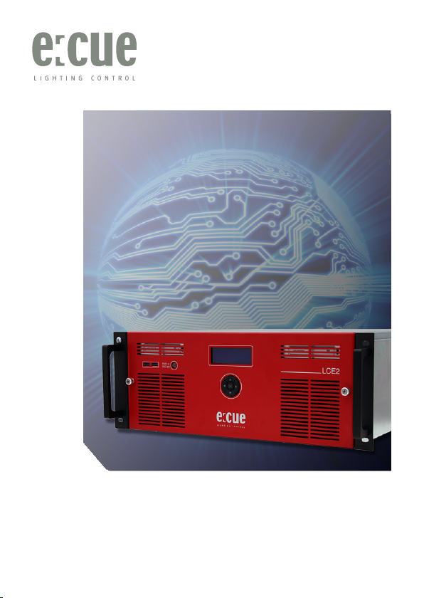
Lighting Control Engine 2
Setup Manual
Page 2

Published by
Traxon Technologies Europe GmbH
Karl Schurz-Strasse 38
Paderborn, Germany
An OSRAM Business
Lighting Control Engine 2
Setup Manual – Edition 2013-10-16
©2013, Traxon Technologies Europe GmbH
All rights reserved
Comments and corrections:
[email protected]
For a most recent version of this manual please visit:
http://www.traxontechnologies.com
Page 3

Table of Contents
English ......................................................................6
Security instructions ................................................................................. 7
Delivery content ........................................................................................ 8
Transport .............................................................................................8
Commissioning ......................................................................................... 8
Inspect the delivery content ................................................................. 8
In case of returning the LCE2 ............................................................... 8
Mounting the LCE2 .............................................................................. 9
Cable lengths....................................................................................... 9
Maintenance ............................................................................................. 9
Cleaning .............................................................................................. 9
Changing filters and hard disks ............................................................ 9
Hard disk replacement and upgrade .................................................. 10
Filters ................................................................................................. 10
Front panel ........................................................................................ 11
Back panel ........................................................................................ 12
Mainboard interfaces ......................................................................... 13
Dry contacts ...................................................................................... 13
Serial ports ........................................................................................ 14
DMX interfaces .................................................................................. 14
Relay interfaces ................................................................................. 15
General recommendations ................................................................. 15
Initial start up .......................................................................................... 16
System Configuration ........................................................................ 16
Setting the network address .............................................................. 16
LCE2-fx video input setup ...................................................................... 20
LCE2 system display .............................................................................. 21
Troubleshooting ..................................................................................... 24
Technical data ........................................................................................ 26
Page 4

Recommended MIDI adapters ........................................................... 27
Deutsch ..................................................................28
Sicherheitshinweise ................................................................................ 29
Lieferumfang .......................................................................................... 30
Transport ...........................................................................................30
Überprüfen des Lieferumfanges ......................................................... 30
Rücksendung der LCE2 ..................................................................... 30
Montage der LCE2 ............................................................................ 31
Kabellängen ....................................................................................... 31
Wartung .................................................................................................. 31
Reinigung ............................................................................................... 31
Wechseln der Filter und Festplatten ................................................... 31
Laufwerkstausch oder -erweiterung ................................................... 32
Filter .................................................................................................. 32
Bedienung und Schnittstellen ................................................................ 33
Frontplatte ......................................................................................... 33
Rückseite........................................................................................... 34
Mainboard-Schnittstellen ................................................................... 35
Digitale Schaltkontakte ...................................................................... 35
Serielle Schnittstellen ......................................................................... 36
DMX-Schnittstellen ............................................................................ 36
Relais-Ausgänge ................................................................................ 37
Allgemeine Empfehlungen .................................................................. 37
Inbetriebnahme ...................................................................................... 38
System-Konfiguration ........................................................................ 38
Programmer-Netzwerk-Adresse .........................................................41
Einrichten des LCE2-fx Videoeinganges ................................................ 43
LCE2 Systemanzeige ............................................................................. 44
Fehlerbehebung ..................................................................................... 47
Technische Daten ................................................................................... 49
Empfohlene MIDI-Adapter .................................................................. 50
Page 5

Setup Manual - Lighting Control Engine 2
Appendix ................................................................51
Dimensions/Abmessungen.....................................................................52
LCE2-fx video inputs .............................................................................. 53
Notes/Notizen ......................................................................................... 54
5
Page 6

Setup Manual - Lighting Control Engine 2
English
6
Page 7
Security instructions
!
!
!
!
!
The product must only be installed and put into operation by a qualified
electrician. The applicable safety regulations and accident prevention
regulations must be observed. Otherwise the unit may be damaged.
Only work on the product when it is de-energized to prevent electrical
shocks. Incorrect handling may damage the unit.
Do not route network, DMX or any other communication line together
with power lines. Data traffic or functions can be disturbed.
The product may only be operated in the operating modes described
in the manual. All other applications are considered to be inappropriate
use. If the product is not used as intended, there is no guarantee that it
will operate safely.
To prevent the device from overheating, only operate it in well-ventilated
environment. The ventilation slots may not be obstructed. Otherwise the
unit may overheat and fail.
Device components can reach high temperatures! Let unit cool down
after operation before mounting or removing unit to avoid burnings.
Repairs may only be carried out by authorized, specially trained personnel to ensure reliability. When in doubt, contact e:cue service. Incorrect
handling may damage the unit
This is a ITE device of class A. If used in domestic environments, this
device may cause radio interferences; in this case the operator can be
asked to undertake corrective measures.
Setup Manual - Lighting Control Engine 2
7
Page 8

Setup Manual - Lighting Control Engine 2
Delivery content
y Lighting Control Engine 2
y Rack mounting rails
y Microsoft® Windows 7™ Professional DVD
y Ethernet cable 2 m CAT5e SFTP
y Printed LCE2 Setup Manual English/German
y Printed Lighting Application Suite System Manual English
y e:cue Lighting Application Suite LCE2 Edition with USB
license dongle
Transport
Only transport the LCE2 in its original packaging. This protects the system from
damage. Only unpack the LCE2 at its installation location. To protect the device
against condensation water, unpack it and wait until all moisture remaining in the
LCE2 has evaporated. Condensation can occur when the device is moved from a
cold to a warm location.
Commissioning
Inspect the delivery content
Unpack the LCE2 and inspect all parts for completeness. Keep the packaging for
use in case of further transport. If there is apparent damage to the device or parts
are missing from the delivery scope, please contact e:cue service.
In case of returning the LCE2
When returning the LCE2 for any reason, e. g. for exchange, be sure to watch the
following notes:
y Always care for proper backup of all user data like shows, images and media files.
Data backup is responsibility of the user, e:cue cannot guarantee that user data
are kept.
y Use the original packaging when returning the LCE2. This ensures protection of
the system and avoids damages.
8
Page 9
Setup Manual - Lighting Control Engine 2
!
Mounting the LCE2
You can mount the LCE2 in all standard 19-inch rack systems. Make sure that the
server rack is sufficiently ventilated and proper cage nuts and rack screws are used.
Cable lengths
All cables, except DMX and Ethernet, should not exceed a length of 3 meters.
Maintenance
Do not remove the front panel while the system is in operation.
Cleaning
To clean the device, disconnect it from the main power supply. Disconnect all
devices connected to the server. Depending on the operating environment, the
server interior must be cleaned. This cleaning may only be carried out by skilled personnel. Do not use any cleaning agents containing solvents (e. g. acetone, alcohol
or thinner) or abrasives. The housing surface can be cleaned with a moist, lint-free
cloth. Ensure that no water penetrates into the housing. This could damage the
electronics.
Changing filters and hard disks
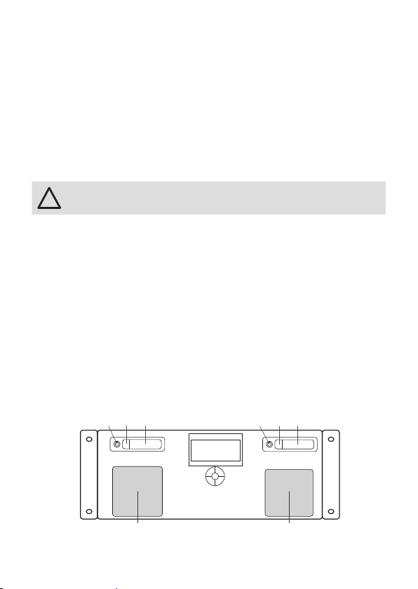
Shut down the system and disconnect from main power before accessing the
internals of the LCE2. To remove the front panel turn the two knurled nuts antclockwise.
1a
1b 1 2b 2b 2
3 3
9
Page 10
Setup Manual - Lighting Control Engine 2
1 Hard disk drive #1 (SSD system drive)
2 Hard disk drive #2 (empty on delivery)
3 Fans with filters
Hard disk replacement and upgrade
If hard disks should be replaced use only Intel 520 series SSDs or compatible types.
As a second hard disk drive the same type can be used. Unlock the drive with the
provided mini keys (1a or 2a), press on the latch (1b or 2b) and the drive bay can
be taken out. After changing the hard drive press the drive bay back into its position
and unlock the drive again.
Filters
The front fan filters of the LCE2 should be cleaned at least every six months,
depending on the environmental conditions regarding dust. Shut down the server
before removing the front cover, take out the filters, clean them with a vacuum
cleaner and remount them. Replace the fan filters every two years. Use appropriate
45 ppi filters of size 92 x 92 mm when replacing them.
10
Page 11
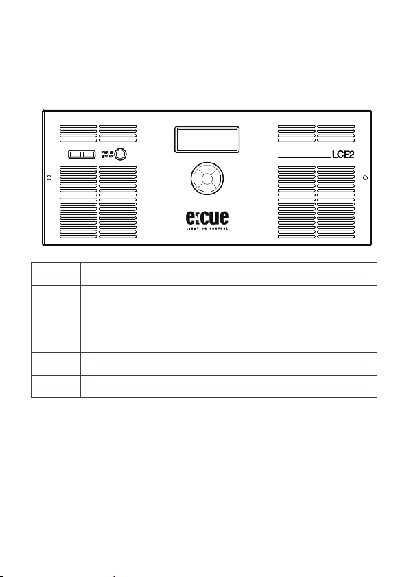
Controls and interfaces
55
66
Front panel
Setup Manual - Lighting Control Engine 2
1
1 2 x USB 3.0 interfaces for USB memory or media drives
2 Power switch and HDD activity indicator
3 Display panel for system and application messages
4 Cursor control keys
5 Fan inlets with filters
6 Knurled nuts for front panel mounting
The USB interfaces can be used to connect media drives like CD/DVD drivers or
USB memory sticks for updates or data exchange. The power switch powers the
system up or down. It also serves as activity indicator for the hard disk drives inside
the LCE2.
On the display panel application messages are displayed, it also is a basic user interface for the Lighting Application Suite running on the LCE2. The four cursor keys
and the centre key allow control of the Lighting Application Suite and data input.
2
3
4
11
Page 12
Setup Manual - Lighting Control Engine 2
!
Back panel
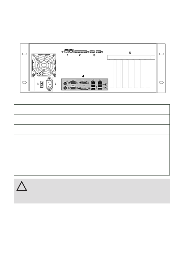
1 2 DMX interfaces in RJ45, input and outputs
2 6 dry contact inputs and 12 V DC contact supply
3 2 relay control outputs, max. 48 V, 2 A; relay 1 left, relay 2 right
4 Mainboard interfaces (USB, PS/2, audio etc.)
5 Extension slots
6 Main AC switch
7 Main AC supply socket, IEC
In the LCE2-fx the two mainboard video outputs are disabled and
only the external video outputs are enabled. To use the mainboard
video outputs you have to enable them in the Windows Control
Panel.
12
Page 13
Setup Manual - Lighting Control Engine 2
12 V DC Out
In 1 ... 6
12 V DC
123456
Gnd
Mainboard interfaces
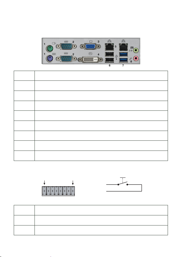
1 2 x PS/2 interfaces, green for mouse, violet for keyboard
2 2 x RS-232 serial interfaces, D-Sub plugs
3 1 x Video out VGA
4 1 x Video out DVI-D
5 2 x Ethernet interfaces 10/100/1000 MBits/s, RJ45
6 2 x USB 2.0 interfaces, black
7 2 x USB 3.0 interfaces, blue
8 1 x Microphone/line audio input
9 1 x Headphone/line audio output
Dry contacts
1 12 V DC, max. 70 mA
2 ... 7 Digital inputs
8 Ground
13
Page 14
Setup Manual - Lighting Control Engine 2
J1
RJ45-2X4
The maximum input for the dry contact inputs is 24 V DC, the minimum voltage is
5 V DC. The 12 V DC supply of the LCE2 is capable to provide up to 70 mA.
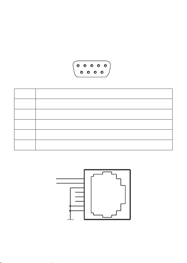
Serial ports
RS 232 - 9 pin male
1
2345
6789
1 n. c.
2 RxD (Receive data)
3 TxD (Transmit data)
4 n. c.
5 Ground
6 ... 9 n. c.
DMX interfaces
DMX1–
DMX1+
14
GND
1
2
3
4
5
6
7
8
Page 15
1 DMX-
!
2 DMX+
3 Common ground
4 n. c.
5 n. c.
6 n. c.
7 Common ground
8 Common ground
Relay interfaces
Setup Manual - Lighting Control Engine 2
NO
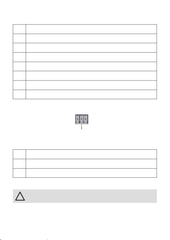
The relays of the LCE2 are capable to switch up to 48 V and a maximum of 2 A.
COM Middle contact
NC Outer contact, closed in off-state (Normally Closed)
NO Outer contact, closed in on-state (Normally Open)
NC
COM
General recommendations
Use shielded network cables with shielding connected to system
ground.
15
Page 16
Setup Manual - Lighting Control Engine 2
!
Initial start up
Connect your devices to the LCE2, at least keyboard, mouse and a monitor. Connect with main power. Switch on the LCE2 with the power switch. The LED indicator lights up in blue while the LCE2 accesses the hard drives.
Do not switch off the server with the main switch, but use the Windows shutdown
function to prevent loss of data.
Change the Windows administrator password within six weeks after
first startup. Otherwise the password will expire and cannot be reset
anymore!
System Configuration
All steps shown here relate to the English version of Microsoft® Windows 7™. The
default language of the operating system is English.
Setting the network address
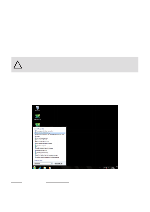
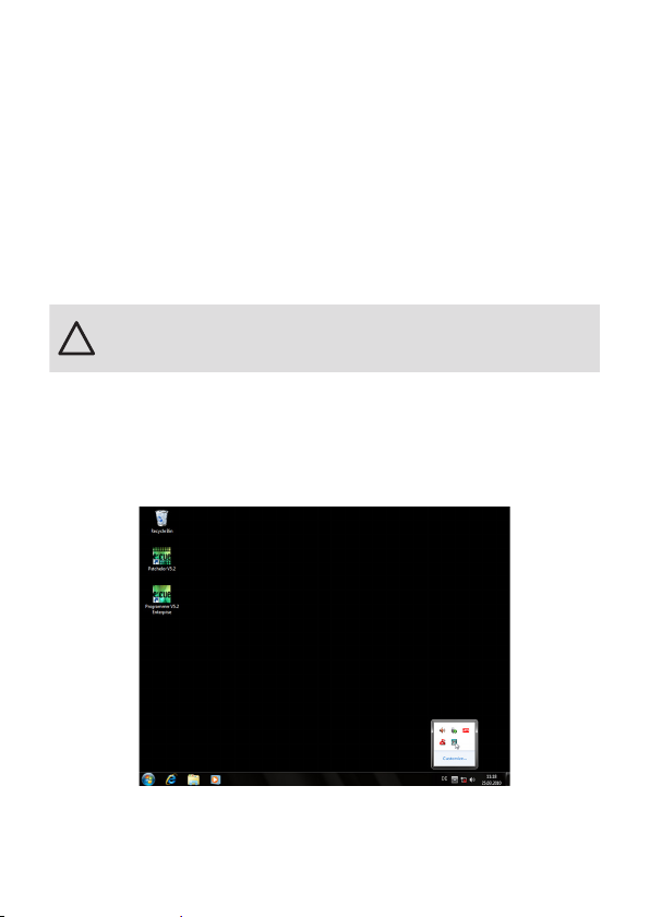
To change the network address of one of the installed network cards, click on the
Start icon and enter Connections in the search box.
16
Page 17
Setup Manual - Lighting Control Engine 2
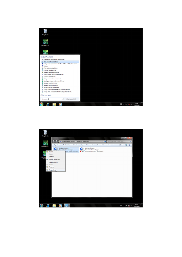
Select View network connections in the hit list.
You now see all available connections. Right-click on the desired connection and
select “Properties”.
17
Page 18
Setup Manual - Lighting Control Engine 2
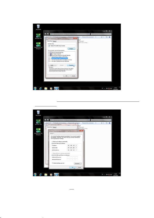
In this open window click on Internet Protocol Version 4 (TCP/IPv4),
then press the Properties button.
Enter the appropriate server address in the network, e. g. 192.178.123.100.
Confirm your input by clicking on the OK button. You can close all windows now.
The network connection is now configured.
18
Page 19
Setup Manual - Lighting Control Engine 2
Programmer’s network settings
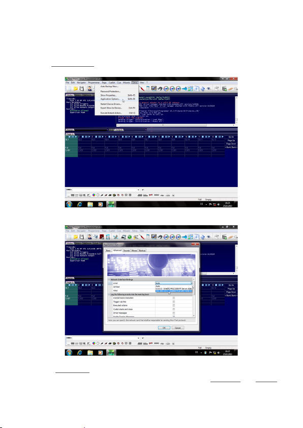
Start the Programmer.
Click on “Extras” and select “Application Options”.
Under the Advanced tab, you can specify which network card the programmer
software e:net outputs to. You can specify this setting for the Art-Net and KiNet
protocols. e:cue recommends only outputting one protocol per network.
19
Page 20
Setup Manual - Lighting Control Engine 2
LCE2-fx video input setup
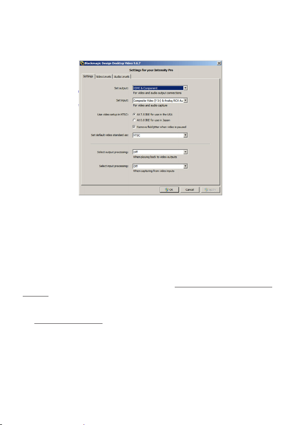
Before using the video input of the LCE2-fx you have to setup the video card.
Open the Blackmagic Design Control Panel from the Windows Control Panel.
Change the video standard to the same standard that your capture source uses.
After you applied the new settings you can start the Programmer and select the
Blackmagic WDM Capture Driver as capture source, e. g. in the Media Player.
The driver will now show the resolution in the combobox as you configured the
Blackmagic Design Control Panel.
Since a restart of the Programmer is required, the Deckling Video Capture
driver might be a more convenient way to setup a capture device with the
Blackmagic Intensity Pro. The Blackmagic Design Control Panel is also needed, if
you want to use the analog input instead of the HDMI input. You need to change
the Set Input option accordingly to the inputs you plan to use.
20
Page 21
Setup Manual - Lighting Control Engine 2
LCE2 system display
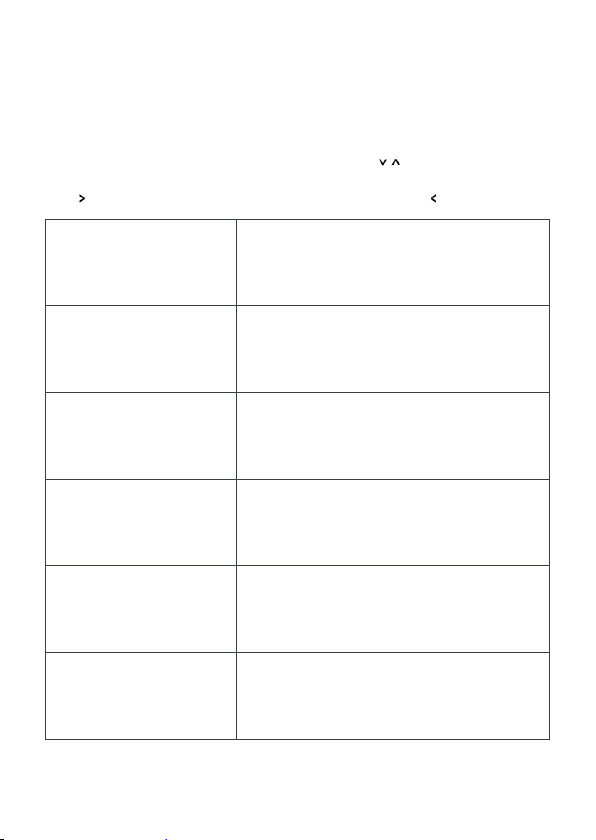
After powering up the system, the Lighting Application Suite will be started by
default. The system display usually cycles through various display pages. You can
select these pages with the up and down cursor keys ( ). In some pages
additional subpages can be selected to view more information with the right cursor
key ( ). To return to the previous page use the left cursor key ( ).
* Programmer 6.1 *
- MASTER SystemName
* Programmer 6.1 *
AppUptime: 2d19h47m
SysUptime: 2d22h49m
ActHandels: 1/48
* 2013-05-27 11:04 *
Zone: UST +1 h (DST)
Twilight AM: 04:33
Twilight PM: 22:11
*2013-05-27 12:33
Sunrise: 05:17
Noon: 13:22
Sunset: 21:36
* LCE2 *
CPU: 4% Temp: 45 C
RAM: 13% Temp: 40 C
Fan: OK 11:04
* LCE2 *
2 days online
2 days running
25 days in use
The LAS Programmer version.
Master or slave system.
The system name.
The LAS Programmer version.
Application uptime in days, hours and minutes.
System uptime in days, hours and minutes.
Number of running cuelists.
System time.
Timezone of system time.
Current astronomical twilight time for sunrise.
Current astronomical twilight time for sunset.
System time.
Current astronomical sunrise time incl. DST.
Current astronomical noon time incl. DST.
Current astronomical sunset time incl. DST.
System type.
Current system CPU usage/CPU temperature.
Current memory usage/case temperature.
Fan status/system time.
System type.
Number of days the system is online.
Number of days the system is running.
Total number of days the system is in use.
21
Page 22
Setup Manual - Lighting Control Engine 2
* Network Adapter *
2 Adapter
* Display Settings *
* Visible Devices *
* Device Manager *
51 Devices
28 Online
23 Offline
* Custom Menu *
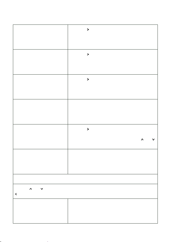
Press the cursor key to see network info.
Press the cursor key to set display settings.
Press the cursor key to see visible devices.
Device Manager overview.
Total number of devices in the Programmer.
Number of devices in online state.
Number of devices in offline state.
Press the cursor key to enter. See the LAS
System Manual for details how to setup user
specific commands and actions. Use the and
cursor keys to select, OK to execute.
* Programmer 6.1 *
DMX: 29fps Load:14%
GUI: 28fps Net: On
Supervisor Trig: On
The Programmer version.
DMX output frame speed/Programmer workload
GUI frame speed/Network enabled.
Supervisor mode enabled/Triggers enabled.
Network adapter menu
Use the and cursor keys to switch between the network adapters. Use the
cursor key to return to the main menu.
* Intel(R) 8257.. *
192.168.178.25
255.255.255.0
00-0B-AB-46-78-A4
22
The selected network interface.
IP address of the interface.
Netmask of the interface.
Hardware address of the interface (MAC).
Page 23
Setup Manual - Lighting Control Engine 2
Display settings
In the display settings you can change the contrast of the display. Use and
keys to select contrast or backlight settings. Press the key to enter the settings
dialogue
* Contrast *
Setup
Press RIGHT
*Contrast Value *
11
®®®®®
Press UP/DOWN change
* Backlight *
Setup
Press RIGHT
* Backlight Value *
ON
Press UP/DOWN change
Press the cursor key to enter the contrast
settings dialogue.
With the and keys change the contrast.
Set value with OK, return to the previous menu
with .
Press the cursor key to enter the backlight
settings dialogue.
With the and keys switch the backlight ON or
OFF. Set value with OK, return to the previous
menu with .
Visible devices
These subpages show the devices attached to the system from the Device
Manager of the LAS. Use and keys to select the device to display. Return to
the previous menu with . The following pages are examples.
* LCE2 I/O Inte... *
USB 33B663000000
The LCE2 I/O interface (dry contacts etc.)
The USB UID.
23
Page 24
* Discovery Ser... *
IP 192.168.123.219
user1 (LCE-001)
The Discovery Service of the LAS.
IP address if the service.
User and system name from Windows.
* Butler PRO *
IP 192.168.123.192
Butler PRO 32/44
* dmxout#3 *
LCE2 I/O Interface
33B663000000
Online
* Term#2 *
Moxa ioLogic E1214
192.168.123.210
Online
A Butler PRO.
IP address of the Butler PRO.
Device name.
The LCE2 DMX output.
Part of the LCE2 I/O interface
The USB UID.
The DMX interface is online.
Name of the device.
The device is a Moxa ioLogic interface.
IP address if the device.
The device is online.
Troubleshooting
Problem Check Reason Details
System does not
power up
DMX outputs
without function
Main switch on the
back panel set to
OFF?
Is the LCE2 I/O
system configured
correctly in the
Device Manager in
Programmer?
If the main switch
is set to OFF, the
frount button will
not work.
The LCE2 I/O
driver must be activated in Programmer. Minimum LAS
Version 6.1.
Setup Manual
LAS System
Manual
Page 25
Setup Manual - Lighting Control Engine 2
DMX Input without
function
Dry contact inputs
do not work
Relay outputs do
not work
Temperature warning on display
Connected Ethernet devices are not
found
The fan speed
varies
Is the LCE2 I/O
system configured
correctly in the
Device Manager in
Programmer?
Is the LCE2 I/O
system configured
correctly in the
Device Manager in
Programmer?
Is the LCE2 I/O
system configured
correctly in the
Device Manager in
Programmer?
Are the fan filters
filled up? Insufficient air flow or
room temperature
too high?
Check correct
e:net bindings in
the Application
Options of the Programmer. Check
correct IP settings
in Windows.
This is correct, the
fans are controlled
by the system
temperature.
The LCE2 I/O
driver must be activated in Programmer. Minimum LAS
Version 6.1.
The LCE2 I/O
driver must be activated in Programmer. Minimum LAS
Version 6.1.
The LCE2 I/O
driver must be activated in Programmer. Minimum LAS
Version 6.1.
If the filters are
blocked or the
room temperature
exceeds 35 °C,
the system will
overheat.
There are at least
two Ethernet ports
in the LCE2. Use
the correct on. The
IP address must
also be defined in
Windows.
LAS System
Manual
LAS System
Manual
LAS System
Manual
Setup Manual
Setup Manual
Setup Manual
25
Page 26

Setup Manual - Lighting Control Engine 2
Technical data
Model numbers EN.LC.9300000 (LCE2)
EN.LC.9400000 (LCE2-fx)
Dimensions (W x H x D) 491 x 176 x 432 mm
19.3 x 6.9 x 17 inch (incl. brackets)
Weight 15 kg
Power supply 100 ... 240 V AC, 50/60 Hz
Power consumption LCE2: 100 W
LCE2-fx: 190 W
Operating temperature 0 ... 35 °C/32 ... 95 °F
Storage temperature -10 ... 70 °C/14 ... 158 °F
Operating/storage humidity 0 ... 95% non-condensing
Protection class IP20
Housing Steel, front powder-coated
Mounting in 19-inch rack systems with rails
Certifications CE, ETL
Maximum cable lengths 3 m
User interface USB or PS/2 keyboard/mouse,
4 lines x 40 chars LC display,
circular keypad
Ethernet ports 2 x 10/100/1000 Mbps
Serial interfaces 2 x RS-232 Sub-D
Keyboard/mouse 2 x PS/2
USB 2 x USB3 (blue, front)
2 x USB3 (blue, rear)
2 x USB2 (black, rear)
DMX 2 x DMX/RDM output/input,
1 kV galvanically isolated
Digital dry contacts 6 x inputs, max. 24 V DC
off: Vin < 1 V DC, on: Vin > 4 V DC
Input current Iin (typical):
Vin = 5 V/Iin = 0.8 mA
Vin = 12 V/Iin = 2.3 mA
26
Page 27
Setup Manual - Lighting Control Engine 2
Vin = 24 V/Iin = 4.8 mA
12 V DC output:
max. 70 mA, overload protected
Relay outputs 2 x SPDT, max. 48 V, 3 A
Graphics LCE2 1 x VGA, 1 x DVI-D
Graphics LCE2-fx 1 x Dual Link DVI-D (adapter)
1 x Mini HDMI (adapter)
1 x Dual Link DVI-I (adapter)
1 x DVI-I (mainboard)
1 x VGA (mainboard)
Video input LCE2-fx DVI Input Capture Card
max. resolution 1920 x 1080 x 24bit
Audio 1 x mic/line input
1 x headphone/line output
Data storage 1 x Removable SSD SATA2 HDD
Certified to EN55022, EN55024, EN/UL60950
ETL LISTED
Conforms to ANSI/UL Std 60950-1
Certified to CAN/CSA STD C22.2 Nr. 60950-1
4006376
Recommended MIDI adapters
y ESI Midi Mate II
y M-Audio MIDISport 2X2 AE USB
y M-Audio USB Uno
27
Page 28

Setup Manual - Lighting Control Engine 2
Deutsch
28
Page 29
Sicherheitshinweise
!
!
!
!
!
Das Produkt darf nur von einer Elektrofachkraft installiert und in Betrieb genommen werden. Die geltenden Sicherheits- und Unfallverhütungsvorschriften sind zu beachten.
Arbeiten an dem Produkt nur im spannungsfreien Zustand durchführen. Anderenfalls kann zu elektrischen Schocks kommen oder das
Gerät wird beschädigt.
Netzwerk, DMX oder andere Kommunikationsleitungen nicht zusammen mit Netzleitung verlegen. Die Datenkommunikation kann gestört
werden oder Funktionen des Gerätes werden eingeschränkt.
Das Produkt darf nur mit den in der Anleitung aufgeführten Betriebsarten betrieben werden. Alle anderen Anwendungen gelten als
sachwidrig. Wird das Produkt nicht bestimmungsgemäß verwendet,
ist kein sicherer Betrieb gewährleistet. Schäden oder Störungen
können die Folge sein.
Um ein Überhitzen des Gerätes zu verhindern, darf es nur in gut
belüfteten Umgebungen betrieben werden. Lüftungsschlitze dürfen
nicht abgedeckt werden. Durch Überhitzung wird das Gerät beschädigt.
Das Gerät oder Teile des Gerätes können im Betrieb heiß werden.
Zur Montage oder Demontage das Gerät ausreichend abkühlen lassen um Verbrennungen zu vermeiden.
Reparaturen am Gerät dürfen nur von geschultem oder ausgebildeten Personal vorgenommen werden. Im Zweifelsfall kontaktieren Sie
e:cue. Fehlerhafte Reparaturen können das Gerät beschädigen.
Dies ist ein ITE-Gerät der Klasse A. Wenn es in privaten Bereichen
betrieben wird, kann es zu Störungen durch HF-Strahlungen in
anderen Geräten kommen. In diesem Fall müssen AbschirmungsMaßnahmen getroffen werden.
Setup Manual - Lighting Control Engine 2
29
Page 30

Setup Manual - Lighting Control Engine 2
Lieferumfang
y Lighting Control Engine 2
y Schienen für Rack-Monatge
y Microsoft® Windows 7™ Professional DVD
y Ethernetkabel 2 m CAT5e SFTP
y LCE2 Setup Manual Englisch/Deutsch
y Lighting Application Suite System Manual Englisch
y e:cue Lighting Application Suite LCE2 Edition inkl. USB-Lizenzdongle
Transport
Transportieren Sie die LCE2 nur in ihrer originalen Verpackung um Schäden zu vermeiden. Entpacken Sie die LCE2 nur am Installationsort. Um Schäden bei Wechsel
von Kälte zu Wärme durch Kondensationswasser zu verhindern, warten Sie nach
dem Auspacken, bis das System die Temperatur am Installationsort angenommen
hat.
Überprüfen des Lieferumfanges
Entpacken Sie die LCE2 und überprüfen Sie die Vollständigkeit des Lieferumfanges.
Bewahren Sie die Verpackung für einen späteren Transport auf. Sollten Komponenten beschädigt sein oder fehlen, wenden Sie sich an Ihrem e:cue-Service.
Rücksendung der LCE2
Falls die LCE2 zurück gesendet muss, z. B. zum Austausch, berücksichtigen Sie
bitte Folgendes:
y Sorgen Sie für eine regelmäßige Datensicherung, diese liegt in der Verantwortung
des Benutzers. e:cue kann nicht garantieren, dass Benutzerdaten bei der Reparatur erhalten bleiben.
30
Page 31
Setup Manual - Lighting Control Engine 2
!
Montage der LCE2
Die LCE2 kann in jedem Standard-19-Zoll-Rack mit den beiliegenden Schienen
montiert werden. Verwenden Sie nur entsprechnde Rackschrauben- und Muttern.
Achten Sie darauf, dass die LCE2 ausreichend belüftet wird.
Kabellängen
Alle Kabelverbindungen, außer Ethernet und DMX, sollen nicht länger als 3 Meter
sein.
Wartung
Entfernen Sie die Frontplatte nicht während des Betriebes!
Reinigung
Bevor Sie das Gerät reinigen, trennen Sie es vom Netz. Trennen Sie alle weiteren
Geräte, die mit dem System verbunden sind. Je nach Umgebungsbedingungen
empfiehlt sich ein Reinigung des Geräteinneren. Diese Reinigung darf nur von
geschultem Personal durchgeführt werden. Verwenden Sie keine Reinigungsmittel mit Lösemitteln wie Azeton, Alkohol oder Verdünner oder mit Schleifmitteln.
Das Gehäuse kann mit einem feuchten, fusselfreien Tuch gereinigt werden. Stellen
Sie sicher, dass kein Wasser in das Gehäuse gelangt. Dieses kann die Elektronik
beschädigen.
Wechseln der Filter und Festplatten
Fahren Sie das System herunter und trennen Sie es vom Netz, bevor Arbeiten darin
vorgenommen werden. Lösen Sie die beiden Rändelschrauben um die Frontplatte
abzunehmen.
31
Page 32
Setup Manual - Lighting Control Engine 2
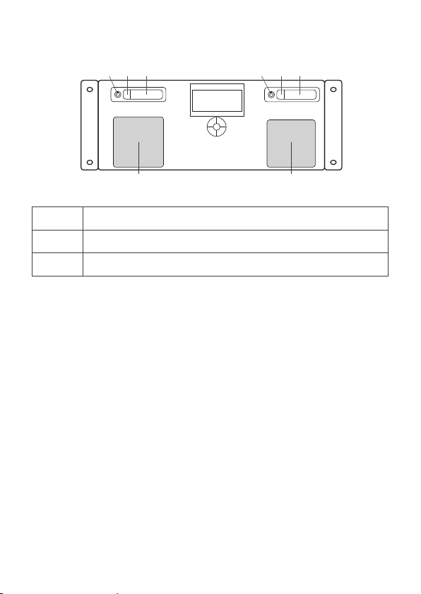
1a
1b 1 2b 2b 2
3 3
1 Laufwerksschaft #1 (SSD-Systemlaufwerk)
2 Laufwerksschacht #2 (bei Lieferung unbestückt)
3 Lüfter mit Filtern
Laufwerkstausch oder -erweiterung
Als Laufwerke dürfen nur Intel 520 Series-SSDs und kompatible Typen verwendet
werden, sowohl für das vorhandene wie für ein zusätzliches Laufwerk. Entriegeln
Sie den Schacht mit den mitgelieferten Rundschlüsseln (1a, 2a), drücken Sie auf
den Verschluss (1b, 2b). Der Laufwerksschacht öffnet sich und die Laufwerke können entnommen werden. Nach dem Wechsel drücken sie den Schlitten zurück in
seine Ursprungsposition und verschließen den Schacht wieder.
Filter
Die Filter der LCE2 sollten mindestens alle sechs Monate gereinigt werden, je nach
Staubbelastung in der Umgebung. Fahren Sie den Server herunter, bevor Sie die
Frontplatte abnehmen, reinigen Sie die Filter mit einem Staubsauer und setzen Sie
sie wieder ein. Die Filter sollten alle zwei Jahre gewechselt werden. Verwenden Sie
passende Filter mit 45 ppi in einer Größe von 92 x 92 mm.
32
Page 33
Bedienung und Schnittstellen
55
66
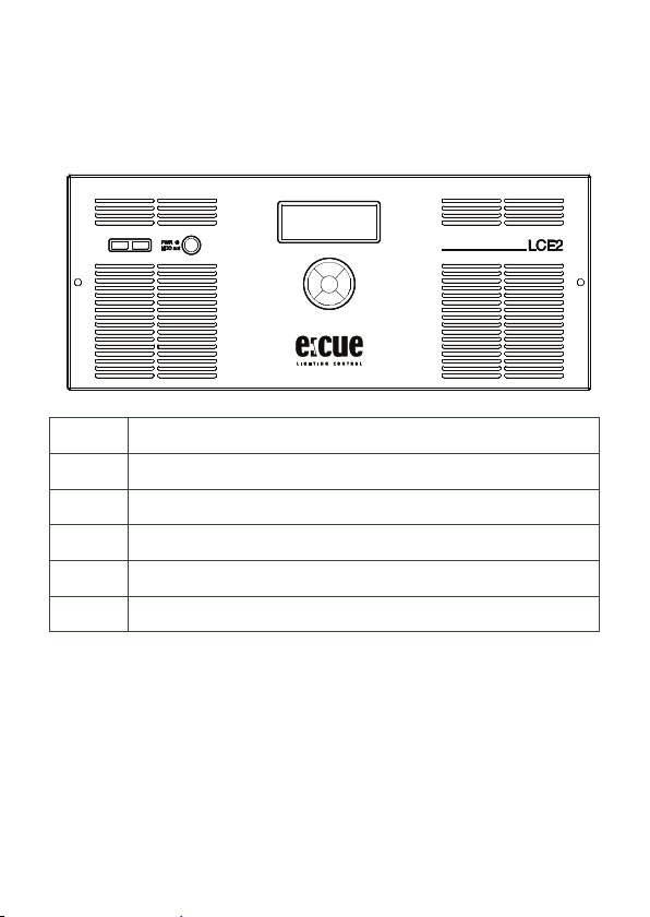
Frontplatte
Setup Manual - Lighting Control Engine 2
1
1 2 x USB 3.0-Schnittstellen für USB-Speicher oder -Laufwerke
2 Netzschalter und Anzeige für Festplattenzugriffe
3 Systemanzeige für System- und Anwendungsmeldungen
4 Cursortasten
5 Lüfteröffnungen mit Filtern
6 Rändelschrauben als Frontplattenbefestigung
Über die USB-Schnittstellen können verwendet werden um CD/DVD-Laufwerke
oder Speichersticks zu nutzen, zum Beispiel zum Datenaustausch. Der Netzschalter
schaltet das System ein und aus. er dient gleichzeitig zur Anzeige von Festplattenaktivitäten in der LCE2.
Auf der Systemanzeige werden Meldungen des Systems oder der Lighting Application Suite (LAS) ausgegeben. Die vier Cursortasten und der OK-Taster in der Mitte
erlauben die Interaktion mit der LAS.
2
3
4
33
Page 34
Setup Manual - Lighting Control Engine 2
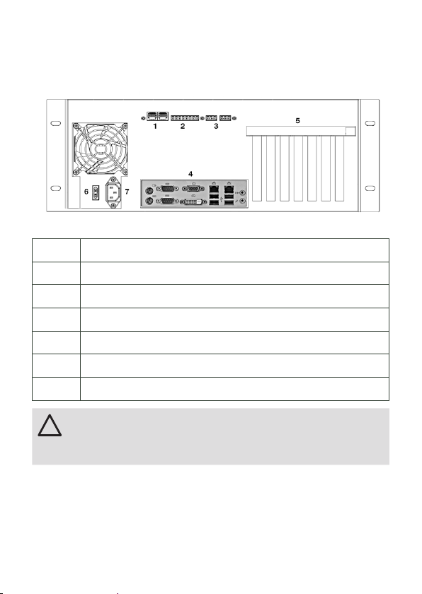
!
Rückseite
1 2 DMX-Schnittstellen in RJ45, Eingänge/Ausgänge
2 6 digitale Schaltkontakte und 12 V Schaltspannung
3 2 Relais-Ausgänge, max. 48 V, 2 A; Relais 1 links, Relais 2 rechts
4 Mainboard-Schnittstellen (USB, PS/2, Audio etc.)
5 Erweiterungsplätze
6 Netzschalter
7 Netzanschluss, IEC
In der LCE2-fx sind die beiden Videoausgänge auf dem Mainboard
ausgeschaltet und nur die externen Ausgänge aktiv. Um sie trotzdem
zu nutzen, müssen sie in den Windows Einstellungen aktiviert
werden.
34
Page 35
Setup Manual - Lighting Control Engine 2
12 V=
In 1 ... 6
12 V=
123456
Masse
Mainboard-Schnittstellen
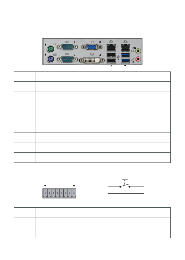
1 2 x PS/2-Schnittstellen, grün für Maus, violett für Tastatur
2 2 x RS-232 serielle Schnittstelle in D-Sub-Steckern
3 1 x Video-Ausgang VGA
4 1 x Video-Ausgang DVI-D
5 2 x Ethernet-Schnittstelle 10/100/1000 MBits/s, RJ45
6 2 x USB 2.0-Schnittstellen, schwarz
7 2 x USB 3.0-Schnittstellen, blau
8 1 x Mikrofon-/Line-Eingang
9 1 x Kopfhörer-/Line-Ausgang
Digitale Schaltkontakte
1 12 V=, max. 70 mA
2 ... 7 Digitale Eingänge
8 Masse
35
Page 36
Setup Manual - Lighting Control Engine 2
J1
RJ45-2X4
Die maximale Eingangsspannung für die Schalteingänge beträgt 24 V=, die minimale Eingangsspannung ist 5V=. Die von der LCE2 gelieferte Schaltspannung darf
maximal mit 70 mA belastet werden.
Serielle Schnittstellen
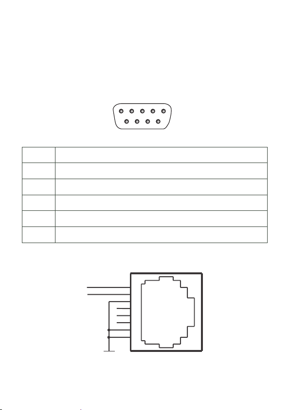
RS-232 - 9-Pin-Stecker
1
2345
6789
1 n. v.
2 RxD (Receive data)
3 TxD (Transmit data)
4 n. v.
5 Masse
6 ... 9 n. v.
DMX-Schnittstellen
DMX1–
DMX1+
36
GND
1
2
3
4
5
6
7
8
Page 37
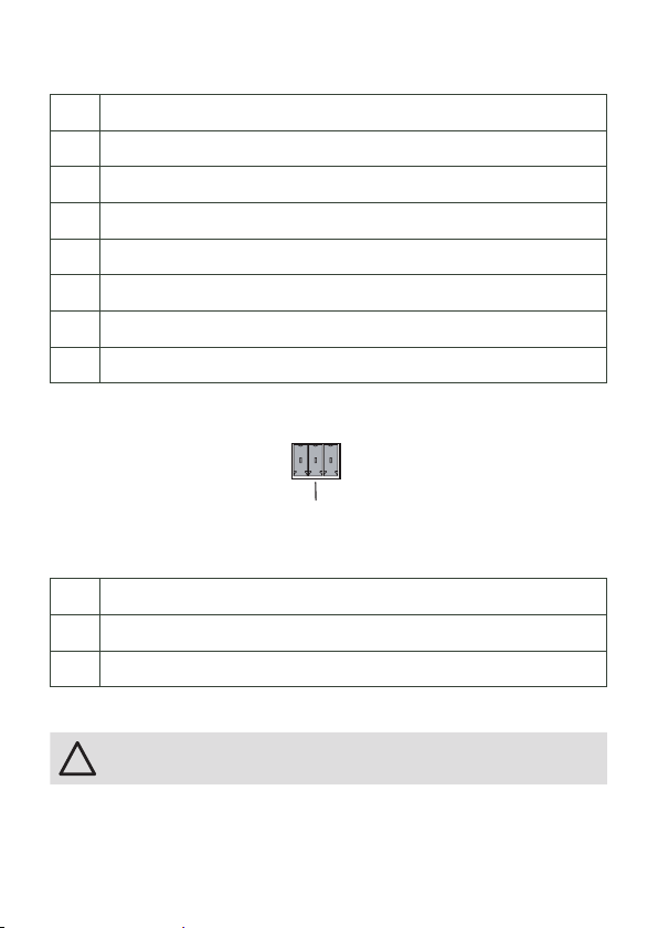
1 DMX-
!
2 DMX+
3 Masse
4 n. v.
5 n. v.
6 n. v.
7 Masse
8 Masse
Relais-Ausgänge
Setup Manual - Lighting Control Engine 2
NO
Die Relais der LCE2 schalten maximal 48 V bei 2 A.
COM Mittelkontakt
NC Schaltkontakt, geschlossen im Aus-Zustand (Normally Closed)
NO Schaltkontakt, geschlossen im Ein-Zustand (Normally Open)
NC
COM
Allgemeine Empfehlungen
Benutzen Sie nur geschirmte Netzwerkkabel und verbinden Sie die
Schirmung mit Systemmasse.
37
Page 38
Setup Manual - Lighting Control Engine 2
!
Inbetriebnahme
Verbinden Sie notwendige Komponenten mit der LCE2 und verbinden Sie sie mit
Netzspannung. Schalten Sie die LCE2 auf der Rückseite ein, die Front-LED leuchtet
blau.
Zum normalen Einschalten der LCE2 drücken Sie den Netzschalter auf der Front.
Zum Ausschalten sollte das Herunterfahrn des Betriebssystems verwendet werden.
Unterbrechen der Netzversorgung kann zum Datenverlust führen. Bei einer Störung
des Betriebssystemes kann der Netzschalter benutzt werden, damit sich die LCE2
ausschaltet.
Ändern Sie das Administrator-Password für Windows innerhalb von
sechs Wochen nach Inbetriebnahme. Danach wird das Passwort
ungültig und kann nicht mehr geändert werden!
System-Konfiguration
Alle hier gezeigten Schritte beziehen sich auf die Englische Version von Microsoft®
Windows 7™, da die LAS mit der englischen Sprachversion geliefert wird.
38
Page 39
Setup Manual - Lighting Control Engine 2
Netzwerk-Adresse
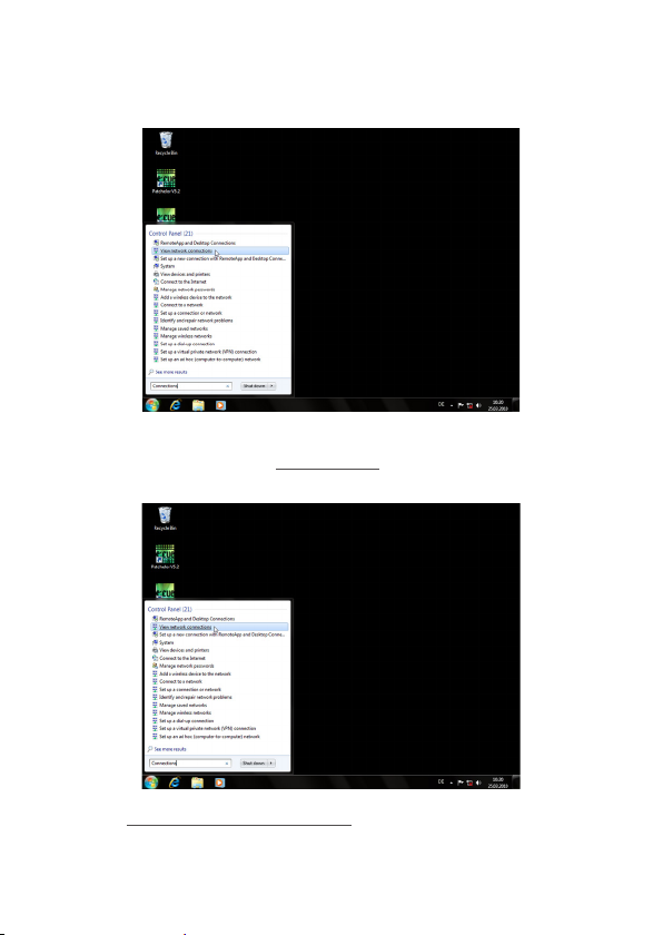
Um die Netzwerk-Adresse(n) der installierten Netzwerkkarte(n) zu ändern, clicken
Sie auf das Start-Icon und geben Connections als Suchbegriff ein.
Wählen sie View network connections in der Ergebnisliste.
39
Page 40
Setup Manual - Lighting Control Engine 2
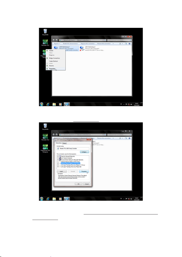
Sie sehen nun alle verfügbaren Netzwerke. Rechts-clicken Sie auf die gewünschte
Netzverbindung und wählen Sie Properties.
In diesem Fenster clicken Sie Internet Protocol Version 4 (TCP/IPv4),
dann den Properties-Button.
40
Page 41
Setup Manual - Lighting Control Engine 2
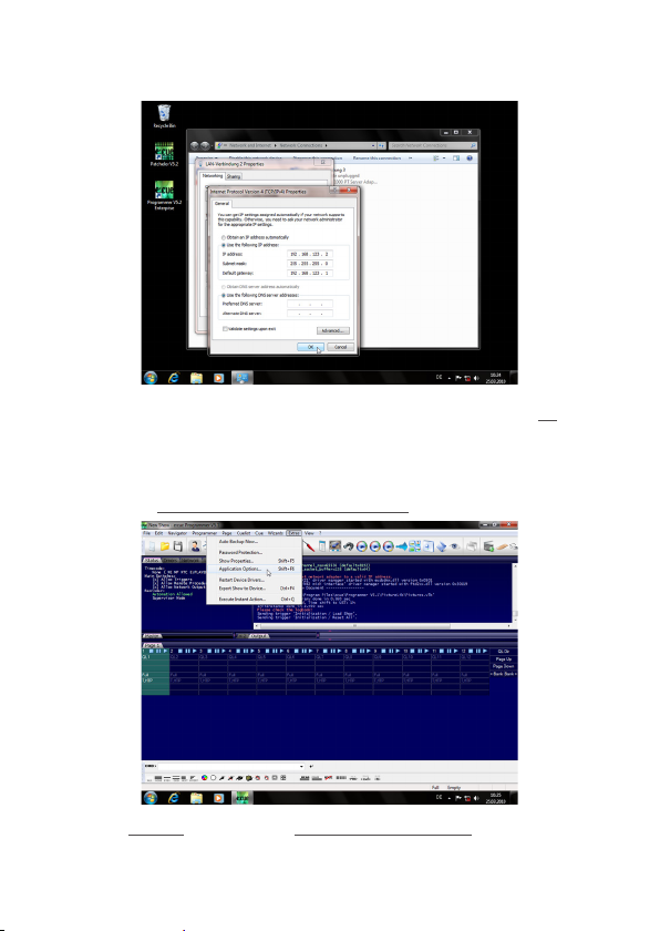
Geben Sie die gewünschte Netzwerk-Adresse ein und bestätigen Sie mit Ok.
Schließen Sie nun alle Fenster, das Netzwerk ist konfiguriert.
Programmer-Netzwerk-Adresse
Starten Sie den e:cue Programmer Enterprise.
Clicken Sie Extras und wählen Sie Application Options.
41
Page 42
Setup Manual - Lighting Control Engine 2
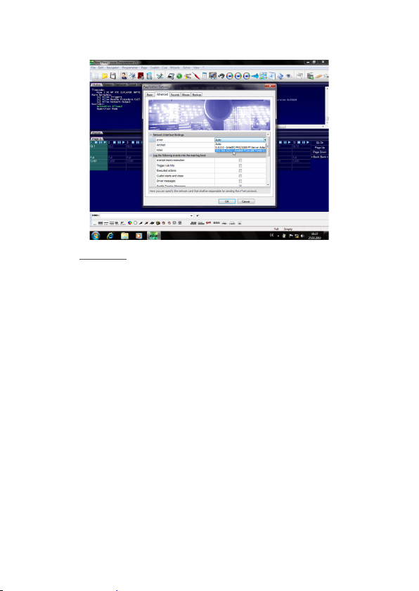
Unter dem Advanced-Tab können Sie wählen, über welche Netzwerkkarte der
Programme e:net-Output sendet. Ebenso können Sie die Einstellungen für die
Art-Net- und KiNet-Protokolle setzen. e:cue empfiehlt, nur ein Protokoll pro
Netzwerkkarte zu verwenden.
42
Page 43
Setup Manual - Lighting Control Engine 2
Einrichten des LCE2-fx Videoeinganges
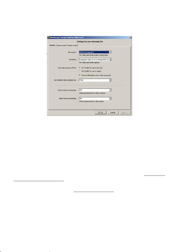
Vor der Nutzung des Videoeinganges der LCE2-fx muss die Video-Karte eingerichtet werden.
Öffnen Sie aus der Windows Systemsteuerung das Blackmagic Design Control
Panel. Stellen Sie die Video-Optionen so ein, dass sie der Bildquelle entsprechen. Nach diesen Einstellungen kann der Programmer gestartet werden und der
Blackmagic Design Control-Treiber steht als Bildquelle zur Verfügung, z. B. im
Media Player. Der Treiber zeigt jetzt die Werte an, die vorher in der Systemsteuerung
konfiguriert wurden.
Da für Änderungen ein Neustart des Programmers notwendig ist, ist der DeckLink
Video Capture driver in der Regel ie bequemere Lösung. Das Blackmagic
Design Control Panel wird auch benötigt, wenn der analoge Eingang genutz werden
soll. In diesem Fall stellen Sie die Set Input option entsprechend.
43
Page 44
Setup Manual - Lighting Control Engine 2
LCE2 Systemanzeige
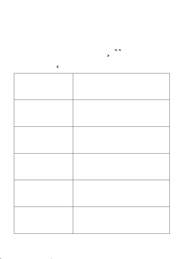
Nach Einschalten des System wird standardmäßig der Programmer der LAS
gestartet. Die Systemanzeige läuft selbstständig durch verschiedene Meldungen.
Gewünschte Anzeigen werden mit den Cursortasten ( ) gewählt. In einigen
Menüpunkten kann mit der Taste Cursor-Rechts ( ) in Untermenüs gewechselt
werden. Um aus einem Untermenü wieder zurück zu kehren, wird die Taste
Cursor-Links benutzt ( ).
* Programmer 6.1 *
- MASTER SystemName
* Programmer 6.1 *
AppUptime: 2d19h47m
SysUptime: 2d22h49m
ActHandels: 1/48
* 2013-05-27 11:04 *
Zone: UST +1 h (DST)
Twilight AM: 04:33
Twilight PM: 22:11
*2013-05-27 12:33
Sunrise: 05:17
Noon: 13:22
Sunset: 21:36
* LCE2 *
CPU: 4% Temp: 45 C
RAM: 13% Temp: 40 C
Fan: OK 11:04
* LCE2 *
2 days online
2 days running
25 days in use
44
Version des Programmers der LAS.
Dies ist ein Master- oder Slave-System.
Der Systemname.
Version des Programmers der LAS.
LAS-Laufzeit in Tagen, Stunden und Minuten.
System-Laufzeit in Tagen, Stunden und Minuten.
Anzahl laufender Cuelisten.
Systemzeit.
Zeitzone der Systemzeit.
Zeit der Morgendämmerung.
Zeit der Abenddämmerung.
Systemzeit.
Sonnenaufgang einschl. Sommerzeit.
Zenith einschl. Sommerzeit.
Sonnenuntergang einschl. Sommerzeit.
Systemtyp.
Akt. CPU-Auslastung und -Temperatur.
Akt. Speicherauslastung und Gehäusetemperatur.
Lüfterstatus und Systemzeit.
Systemtyp.
Anzahl Tage im Online-Status.
Anzahl Tage Systemlaufzeit.
Gesamtzahl Tage Systemnutzung.
Page 45
Setup Manual - Lighting Control Engine 2
* Network Adapter *
2 Adapter
* Display Settings *
* Visible Devices *
* Device Manager *
51 Devices
28 Online
23 Offline
* Custom Menu *
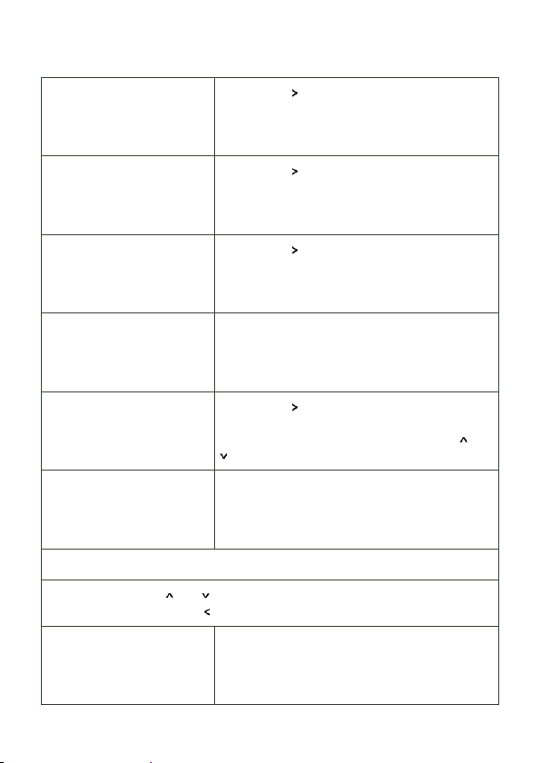
Drücken der Cursortaste für weitere Infos zu
Netzwerk-Anschlüssen.
Drücken der Cursortaste für Display-Einstellungen.
Drücken der Cursortaste für Informationen zu
aktiven Treibern.
Device Manager-Übersicht.
Gesamtzahl Geräte im Programmer.
Anzahl Geräte im Online-Status.
Anzahl Geräte im Offline-Status.
Drücken der Cursortaste für kundenspezifische
Funktionen. Details dazu im LAS System Manual.
Auswahl der Funktion mit den Cursortasten und
, die OK-Taste startet die Funktion.
* Programmer 6.1 *
DMX: 29fps Load:14%
GUI: 28fps Net: On
Supervisor Trig: On
Version des Programmers der LAS.
DMX-Out-Geschwindigkeit, Programmer-Last.
GUI-Geschwindigkeit/Netzwerk-Status.
Benutzer-Status/Triggers aktiv.
Menü Netzwerk-Anschlüsse
Mit den Cursortasten und kann zwischen den Netzwerkadaptern gewählt
werden. Mit der Cursortaste geht es zurück ins Hauptmenü.
* Intel(R) 8257.. *
192.168.178.25
255.255.255.0
00-0B-AB-46-78-A4
Gewählte Schnittstelle.
IP-Adresse der Schnittstelle.
Netmask der Schnittstelle.
Hardware-Adresse der Schnittstelle (MAC).
45
Page 46
Setup Manual - Lighting Control Engine 2
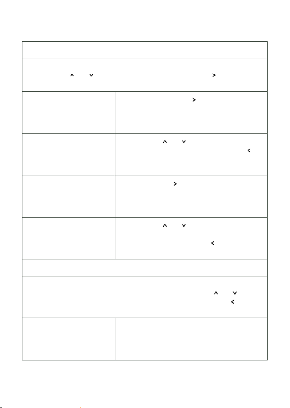
Display-Einstellungen
In diesem Menü können Kontrast und Hintergrundbeleuchtung eingestellt werden.
mit den Tasten und werden die Funktionen ausgewählt, mit die eigentliche
Einstellung aufgerufen.
* Contrast *
Setup
Press RIGHT
*Contrast Value *
11
®®®®®
Press UP/DOWN change
* Backlight *
Setup
Press RIGHT
* Backlight Value *
ON
Press UP/DOWN change
Drücken der Cursortaste zum Einstellen des
Kontrastes.
Mit den Tasten und wird der Kontrast justiert.
Mit OK wird der Wert gespeichert, die Taste
führt ins übergeordnete Menü.
Drücken der Taste zum Einstellen der
Hintergrundbeleuchtung.
Mit den Tasten und wird die Hintergrundbeleuchtung ein- oder ausgeschaltet. Mit OK wird
der Wert gespeichert, die Taste führt ins
übergeordnete Menü.
Aktive Treiber
Diese Untermenüs zeigen alle über den Device Manager des Programmers
eingebundenen Geräte und Schnittstellen. Mit den Cursortasten und können
die Geräte ausgewählt werden. Zurück zum Hauptmenü mit der Taste . Folgend
nur einige Beispiele.
* LCE2 I/O Inte... *
USB 33B663000000
Das LCE2 I/O-Interface (Schaltkontakte etc.)
Die USB UID des Interfaces.
46
Page 47
Setup Manual - Lighting Control Engine 2
* Discovery Ser... *
IP 192.168.123.219
user1 (LCE-001)
* Butler PRO *
IP 192.168.123.192
Butler PRO 32/44
* dmxout#3 *
LCE2 I/O Interface
33B663000000
Online
* Term#2 *
Moxa ioLogic E1214
192.168.123.210
Online
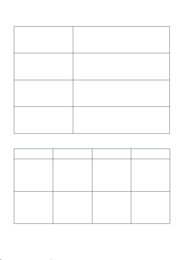
Der Discovery Service der LAS.
IP-Adresse des Service.
Username und Systemname in Windows.
Ein Butler PRO.
IP-Adresse des Butler PRO.
Systemname aus dem Device Manager.
Die LCE2 DMX-Ausgänge.
Teil des LCE2 I/O-Interface
Die USB UID des Interface.
Das DMX-Interface ist online.
Gerätename im System.
Das Gerät ist ein Moxa ioLogic-System
IP-Adresse des Systems.
Das System ist online.
Fehlerbehebung
Problem Zu prüfen Grund Details
Das System
lässt sich nicht
einschalten
DMX-Ausgänge
funktionieren nicht
Ist der Netzschalter auf der Rückseite auf AUS?
Ist das LCE2
I/O-System im
Device Manager
des Programmer
aktiviert?
Ist der Hauptschalter auf AUS, lässt
sich das System
von der Front nicht
einschalten.
Der Treiber des
LCE2 IO-System
muss eingebunden
sein.
Setup Manual
LAS System
Manual
47
Page 48
Setup Manual - Lighting Control Engine 2
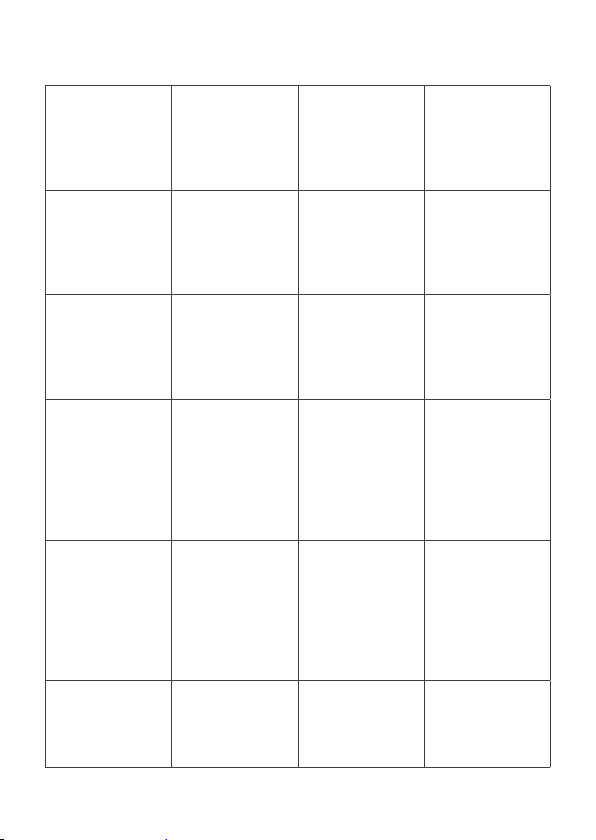
DMX-Eingänge
funktionieren nicht
Schalteingänge
funktionieren nicht
Relaisausgänge
funktionieren nicht
Temperatur-Warnung im Display
Angeschlossene
Ethersysteme
werden nicht
erkannt
Die LüfterGeschwindigkeit
wechselt
Ist das LCE2
I/O-System im
Device Manager
des Programmer
aktiviert?
Ist das LCE2
I/O-System im
Device Manager
des Programmer
aktiviert?
Ist das LCE2
I/O-System im
Device Manager
des Programmer
aktiviert?
Sind die Lüfterfilter
verstopft? Unzureichende Luftzufuhr? UmgebungsTemperatur zu
hoch?
e:net-Zuweisungen
in den Application
Options des Programmers prüfen.
IP-Zuweisung in
Windows prüfen.
Das ist korrekt.
Die Lüfter-Gescheindigkeit wird
geregelt.
Der Treiber des
LCE2 IO-System
muss eingebunden
sein.
Der Treiber des
LCE2 IO-System
muss eingebunden
sein.
Der Treiber des
LCE2 IO-System
muss eingebunden
sein.
Wenn die Filter
verstopft sind oder
die Umgebungstemeperatur
höher als 35 °C,
überhitzt sich die
LCE2.
Es gibt mindestens
zwei EthernetPorts in der
LCE2. Die richtige
IP-Adresse muss
in Windows zugewiesen werden.
LAS System
Manual
LAS System
Manual
LAS System
Manual
Setup Manual
Setup Manual
Setup Manual
48
Page 49

Setup Manual - Lighting Control Engine 2
Technische Daten
Modellnummern EN.LC.9300000 (LCE2)
EN.LC.9400000 (LCE2-fx)
Abmessungen (B x H x T) 491 x 176 x 432 mm (incl. Montagewinkel)
Gewicht 15 kg
Stromversorgung 100 ... 240 V~, 50/60 Hz
Leistungsaufnahme LCE2: 100 W
LCE2-fx: 190 W
Betriebstemperatur 0 ... 35 °C
Lagertemperatur -10 ... 70 °C
Betriebs-/Lagerfeuchte 0 ... 95% nicht kondensierend
Schutzklasse IP20
Gehäuse Stahl, Front pulverbeschichtet
Montage in Standard-19-Zoll-Racks, mit Schienen
Zertifizierungen CE, ETL
Maximale Kabellängen 3 m (außer DMX, Ethernet)
Bedienerschnittstellen USB oder PS/2 Tastatur/Maus,
4 Zeilen x 40 Zeichen LC-Display,
Cursortasten
Ethernet-Ports 2 x 10/100/1000 Mbps
Serielle Schnittstellen 2 x RS-232 Sub-D
Tastatur/Maus 2 x PS/2 oder über USB
USB 2 x USB3 (blau, Front)
2 x USB3 (blau, Rückseite)
2 x USB2 (schwarz, Rückseite)
DMX 2 x DMX/RDM Ausgang/Eingang,
1 kV galvanisch isoliert
Digitale Schalteingänge 6 x Eingang, max. 24 V=
aus: Vin < 1 V=, ein: Vin > 4 V DC
Eingangsstrom (typisch):
Vin = 5 V/Iin = 0,8 mA
Vin = 12 V/Iin = 2,3 mA
Vin = 24 V/Iin = 4,8 mA
49
Page 50
Setup Manual - Lighting Control Engine 2
12 V= Ausgang:
max. 70 mA mit Überlastschutz
Relaisausgänge 2 x SPDT, max. 48 V, 3 A
Graphik LCE2 Onboard-Grafik
1 x VGA, 1 x DVI-D
Graphik LCE2-fx 1 x Dual Link DVI-D (Adapter)
1 x Mini HDMI (Adapter)
1 x Dual Link DVI-I (Adapter)
1 x DVI-I (Onboard)
1 x VGA (Onboard)
Video-Eingang LCE2-fx DVI Input Capture Card
max. Auflösung 1920 x 1080 x 24 bit
Audio 1 x Mikrofon-/Line-Eingang
1 x Kopfhörer-/Line-Ausgang
Massenspeicher 1 x SSD SATA2 HDD
Zertifiziert nach EN55022, EN55024, EN/UL60950.
ETL-gelistet.
Entspricht ANSI/UL Std 60950-1.
Zertifiziert nach CAN/CSA STD C22.2 Nr. 60950-1.
4006376
Empfohlene MIDI-Adapter
y ESI Midi Mate II
y M-Audio MIDISport 2X2 AE USB
y M-Audio USB Uno
50
Page 51

Setup Manual - Lighting Control Engine 2
Appendix
51
Page 52
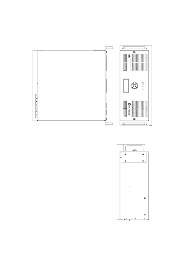
Setup Manual - Lighting Control Engine 2
430
490
177
10.5 420 40
Dimensions/Abmessungen
All dimensions in mm/Alle Abmessungen in mm
52
Page 53
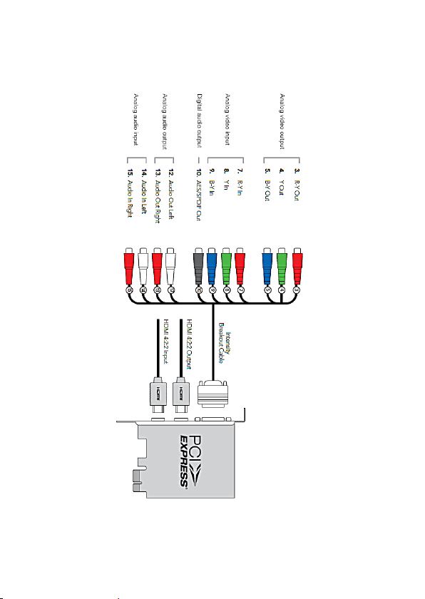
LCE2-fx video inputs
Setup Manual - Lighting Control Engine 2
The complete manual for the LCE2-fx video input card can be downloaded from the
e:cue or Traxon website, chapter LCE2 documentation.
53
Page 54

Setup Manual - Lighting Control Engine 2
Notes/Notizen
54
Page 55

Setup Manual - Lighting Control Engine 2
55
Page 56

Downloads and more information at
www.traxontechnologies.com and www.ecue.com
HONG KONG SHANGHAI TOKYO SINGAPORE ROTTERDAM COLOGNE LONDON
MADRID MILAN PARIS ISTANBUL DENMARK MOSCOW WARSZAWA VIENNA
NEW YORK TORONTO DUBAI BUENOS AIRES MEXICO D.F. SAO PAULO COLOMBIA
MUMBAI
FLEXIBILITY, SIMPLICITY & INNOVATION IN LIGHTING SOLUTIONS & SERVICES
 Loading...