

Page 1
Butler PRO
Setup Manual
Page 2

Butler PRO Setup Manual
Edition/Ausgabe: 2013-07-26
Published by/Herausgegeben von:
Traxon Technologies Europe GmbH
Karl Schurz-Strasse 38
Paderborn, Germany
©2013, Traxon Technologies Europe GmbH
All rights reserved/Alle Rechte vorbehalten
Comments to/Bemerkungen an:
[email protected]
Page 3

Table of Contents
English ......................................................................5
Safety instructions .................................................................................... 6
System description
System diagram
Connections
Frontplane
Backplane
Terminal pinning
Mounting and installation
Unit distribution
User interface
Operational messages
Display and keypad use
Parameter setup
Device Info mode
Setup mode
Advanced Settings mode
Test mode.......................................................................................... 14
Network parameters
Connecting more than one Butler PRO
Firmware update
Troubleshooting
Technical specifications
................................................................................... 7
....................................................................................... 7
............................................................................................. 8
........................................................................................... 8
........................................................................................... 8
....................................................................................... 8
......................................................................... 9
.................................................................................... 9
........................................................................................... 9
............................................................................ 10
..................................................................... 11
..................................................................................... 11
............................................................................... 12
....................................................................................... 12
................................................................... 14
.......................................................................... 18
.............................................. 20
.................................................................................... 21
..................................................................................... 22
......................................................................... 24
Deutsch ..................................................................26
Sicherheitshinweise ................................................................................ 27
Page 4

Gerätebeschreibung ............................................................................... 28
Systemdiagram
Anschlüsse
Frontplatte
Rückseite........................................................................................... 29
Pin-Belegung
Montage
Platzierung im Rack
Benutzeroberfläche
Betriebsanzeigen
Nutzen der Anzeige und des Tastenkranzes
Parameter-Einstellungen
Grundeinstellungen
Erweiterte Einstellungen (Advanced Settings)
Test-Modus (Test mode)
Netzwerk-Parameter
Anschluss mehrerer Butler PRO
Firmware-Update
Fehlerbehebung
Technische Daten
...................................................................................... 28
............................................................................................. 29
......................................................................................... 29
.......................................................................................... 29
................................................................................................. 30
........................................................................... 30
................................................................................ 30
.................................................................................... 31
....................................... 32
........................................................................ 32
............................................................................ 33
..................................... 35
.................................................................... 36
.......................................................................... 39
......................................................... 41
................................................................................... 42
..................................................................................... 43
................................................................................... 44
Appendix ................................................................46
Dimensions/Abmessungen.....................................................................47
Notes/Notizen
......................................................................................... 48
Page 5

Setup Manual - Butler PRO
English
5
Page 6
Setup Manual - Butler PRO
!
!
!
!
!
!
Safety instructions
The product must only be installed and put into operation by a qualified
electrician. The applicable safety regulations and accident prevention
regulations must be observed. Otherwise the unit may be damaged.
Only work on the product when it is de-energized to prevent electrical
shocks. Incorrect handling may damage the unit.
Do not route network, DMX/e:pix or any other communication line
together with power lines. Data traffic or functions can be disturbed.
The product may only be operated in the operating modes described
in the manual. All other applications are considered to be inappropriate
use. If the product is not used as intended, there is no guarantee that it
will operate safely.
To prevent the device from overheating, only operate it in well-ventilated
environment. The ventilation slots may not be obstructed. Otherwise the
unit may overheat and fail.
Device components can reach high temperatures! Let unit cool down
after operation before mounting or removing unit to avoid burnings.
Repairs may only be carried out by authorized, specially trained personnel to ensure reliability. When in doubt, contact e:cue service. Incorrect
handling may damage the unit
It is imperative that main power is supplied via an isolating device and
a circuit-breaking device (power contactor) in any case, which can be
controlled at all times.
6
Page 7
Setup Manual - Butler PRO
System description
The e:cue Butler PRO is a 16 channel DMX/RDM or e:pix interface that acts as an
interface between a server running the e:cue Lighting Application Suite and devices
with DMX512 or e:pix connections. The Butler PRO usually gets mounted in a
universal 19-inch rack system or on walls or ceilings.
The server connection is a standard CAT5 RJ45 based Ethernet interconnect. The
device connection is also RJ45 based. All usual CAT5 RJ45 cables can be used.
Please note that e:net requires an isolated network segment and cannot
operate properly when using e. g. Internet traffic or video/audio streaming in the same network simultaneously.
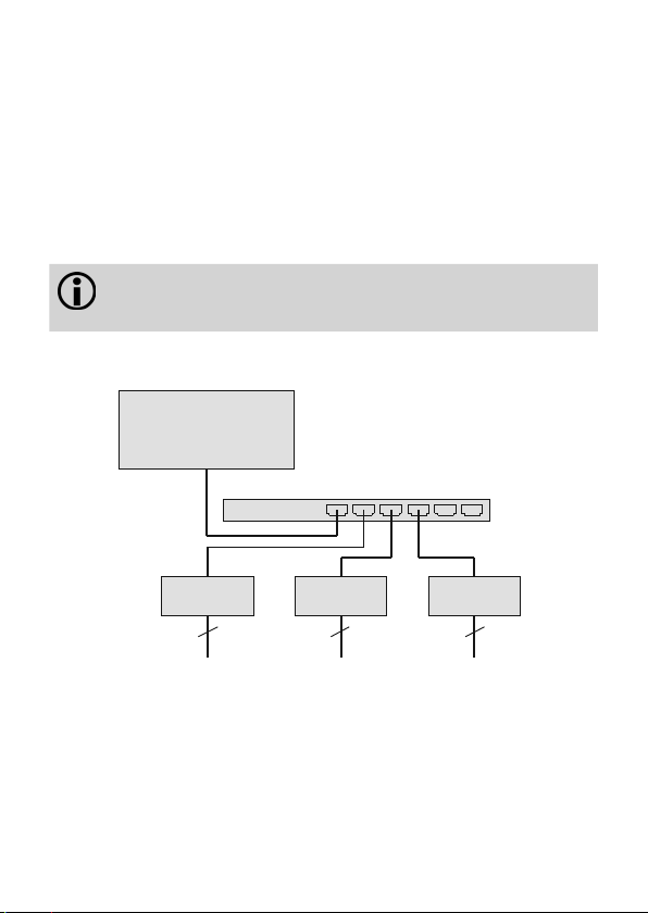
System diagram
e:cue LAS
Ethernet switch
Butler PRO Butler PRO Butler PRO
16 x output channels
DMX512/RDM or e:pix
16 x output channels
DMX512/RDM or e:pix
16 x output channels
DMX512/RDM or e:pix
Use standard CAT5 RJ45 Ethernet cabling between server, switch and Butler
PRO. Connection without Ethernet switch and with an Ethernet cross cable is not
recommened. To connect DMX using a XLR5 type plugs, please use a adaptor
cable, item number 40005, available as accessory or contact your nearest e:cue
distributor for a suitable adaptor cable.
7
Page 8
Setup Manual - Butler PRO
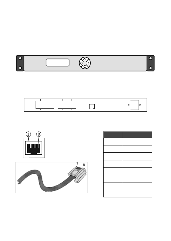
System display
Cursor keys
OK key (center)
OK
Status >
online DMX 35Fps
Ethernet/e:net Power
Connections
Frontplane
Backplane
Output ports 1 ... 16
1 3 5 7
2 4 5 6
Terminal pinning
9 11 13 15
10 12 14 16
Ethernet
pin no. signal
1 DMX-/e:pix-
2 DMX+/e:pix+
3 GND
4 n/c
5 n/c
6 n/c
7 n/c
8 n/c
8
Page 9
Setup Manual - Butler PRO
Cursor keys
OK key (center)
Mounting and installation
Mount the Butler PRO in a standard 19-inch rack system. Use appropriate rack
screws, cage nuts and spring clips for mounting.
Unit distribution
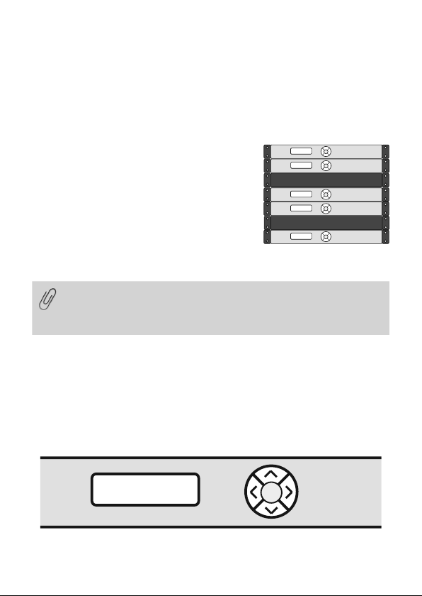
As the Butler PRO has no active cooling, place a
maximum of two units together, leave one unit free
or place a passive device, followed by the next two
units. Additionally care for:
y closing of unused units with rack plates
y mounting in a fan-ventilated closed rack
y placement of the rack in an air conditioned room
Connect the Butler PRO with the outputs of the Ethernet switch and with power.
When installing and mounting more than one Butler PRO in factory state,
make sure that only one Butler PRO gets connected and configured at
one time. If connecting more than one device with the factory IP address
(192.168.123.1) the Ethernet connection will not work
User interface
The Butler Pro comes with a circular keypad and an LC display for operation
and setup. During regular operation the Butler PRO displays status and operational messages on the display. When in setup mode, parameters and values are
displayed, the keypad is used for selecting parameters and changing values. Only
keypads, that are allowed at a certain state, are lit up, either in operational or in
setup mode. This picture is the Butler PRO DMX.
Status >
online DMX 35Fps
OK
9
Page 10

Setup Manual - Butler PRO
After powering up the Butler PRO, the loader shows the loading progress and
revision levels of the loader and the firmware. After loading is completed, the Butler
PRO enters operational mode. The setup mode must be selected separately.
During online operation, usually the IP address and other network parameters are
shown, also the host address of the server running the Programmer of the Lighting
Application Suite. All used values for parameters are just examples, they depend on
the configuration of your Butler PRO.
Operational messages
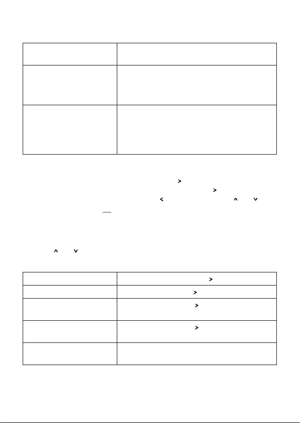
After powering-up and loading the Butler PRO cycles through this set of status
messages (DEVICENAME is the name given via manual or online setup):
Butler PRO <DMX>
©2013 traxon/ecue
Butler PRO <EPIX>
©2013 traxon/ecue
*** ERROR ***
no snapshot found
DEVICENAME
<offline>
DEVICENAME
no output
DEVICENAME
IP: 192.168.123.123
DEVICENAME
MASK: 255.255.255.0
DEVICENAME
<online>
DEVICENAME
Mode: DMX 35 Fps
10
Start screen of the Butler PRO DMX.
Start screen of the Butler PRO e:pix.
After booting the Butler PRO is offline (no LAS
server present) and no snapshot was stored
for offline state. Press the OK-key to clear the
message and save a snapshot for offline state as
shown later.
The Butler PRO is in offline mode and not connected to the Programmer of the LAS.
The Butler PRO does not output any data (no
snapshots defined).
The IP address of this Butler PRO.
The netmask that is used for the IP connection,
default is 255.255.255.0
The Butler PRO is in online mode, connected to
the Programmer of the LAS.
The Butler PRO DMX name and speed, the maximum possible framerate is 35 fps
Page 11
Setup Manual - Butler PRO
DEVICENAME
Mode: EPIX 31 Fps
DEVICENAME
Connected to:
DEVICENAME
192.168.123.100
*** WARNING ***
temperature high!
The Butler PRO e:pix name and speed, the maximum possible framerate is 35 fps
The IP address of the LAS server the Butler PRO
is connected to.
The Butler PRO has exceeded the allowed
internal temperature. The actual temperature is
displayed. Switch off the Butler PRO to cool it
down. Check mounting conditions in the installation chapter of this manual.
Display and keypad use
Displayed messages without a right angle bracket ( ) are info messages. Messages
with a right angle bracket are entries into submenues. Use the
submenues and parameter settings. Use the key to return. Use the and keys
to select parameters. Use OK to acknowldge settings or selections with a
checkmark or a cross. Only keys that are valid entries are lit up on the keypad.
key to enter
Parameter setup
Using the and key from the main menue you can step manually through the
first-level menu.
Device Info >
Setup >
Status >
online DMX 35 Fps
Status >
online EPIX 31 Fps
DEVICENAME
<online>
Enter Device Info mode with key
Enter Setup mode with key.
Enter Status mode with key for the
Butler PRO DMX.
Enter Status mode with key for the
Butler PRO e:pix.
Returned to the default display.
11
Page 12
Setup Manual - Butler PRO
Device Info mode
Info IP
192.168.123.250
Info MAC
00:16:1c:f1:17:b7
Info FW Version
1.0.123
Info FPGA Version
1.0.1
Info HW rev.
1
Info Keypad Version
1.0.5
Info connected to
192.168.123.100
Info temperature
37 C
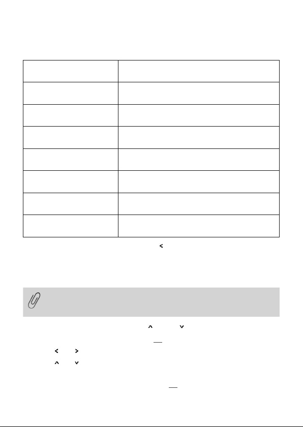
Leave the Device Info mode by pressing the
The IP address of this Butler PRO.
The MAC address of this Butler PRO.
The current firmware version installed-
The FPGA command set version installed.
The hardware revision level of this Butler PRO.
The firmware version of the keypad controller.
The IP address of the LAS server.
The internal temperature of the Butler PRO in
degree Celsius.
key.
Setup mode
Selecting and changing parameter values
In delivery state the setup dialogue is password-protected. The default
password is “ecue”. The password can be changed or deleted in the
online configuration with the Programmer.
y Cycle through the parameters with the and the keys.
y Select the parameter to change with the OK key.
y Use the and keys to select the position to change.
y Use the and key to change the value. Keep the key pressed for a fast change.
y Move the cursor to the right and select the cross to cancel the change, select the
checkmark to make the entry valid. Press the OK key
12
Page 13
Setup Manual - Butler PRO
y For the device name press the OK key to initialize editing mode and select position
and value as above. Press OK again to get to the command selection in the top
row. With the
or key select to save, cancel or delete characters. Select the
cross to cancel, the checkmark to apply the changes or the back-arrow to delete
the characters in the name. Press the OK key.
With the parameter Advanced settings > an additional level of functions is
entered for special features. Use the
key to leave this menu or any other menu
level to return to operational mode. In the setup parameters there is an additional
command set for Test Mode. Select this test mode by pressing the right-key when
Enter Test Mode > is displayed.
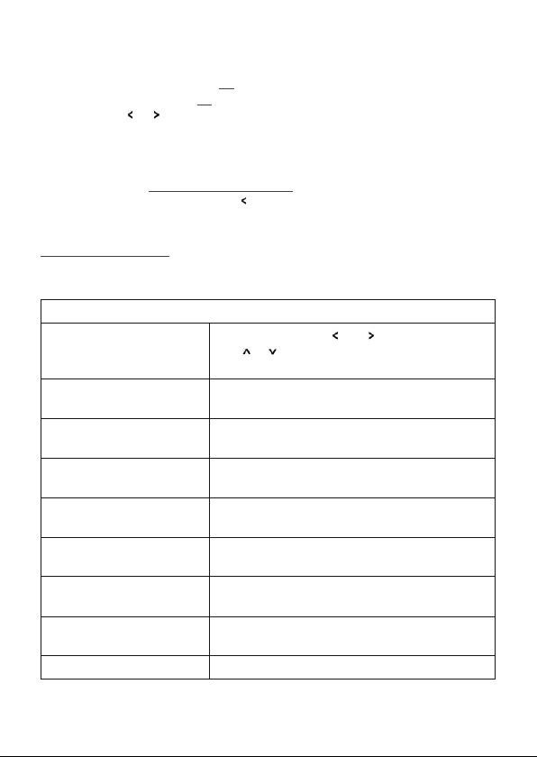
Setup parameters and values
Standard parameters
enter Password
Setup IP
192.168.123.200
Setup Subnet Mask
255.255.255.000
Setup Gateway
192.168.123.001
Setup NAME
Butler PRO
Setup GROUPID
001
Setup STARTUP
show snapshot1
Setup OFFLINE
show snapshot2
Advanced settings >
With the cursor keys
or characters. Press OK to enter the
with
password.
The IP address of the Butler PRO. Factory default
is 192.168.123.1
The subnet mask. Default is
255.255.255.0
The network gateway. If no gateway is use,
set to 0.0.0.0
The device name, used in most displays.
Set the group id for synchronisation of snapshots
in a set of Butler PRO.
Setup the show to display on startup, snapshot 1,
snapshot 2 or no output.
Setup the show to display if the Butler PRO is offline, select snapshot 1, snapshot 2 or no output.
Enter the Advanced Settings mode.
and select position and
13
Page 14
Setup Manual - Butler PRO
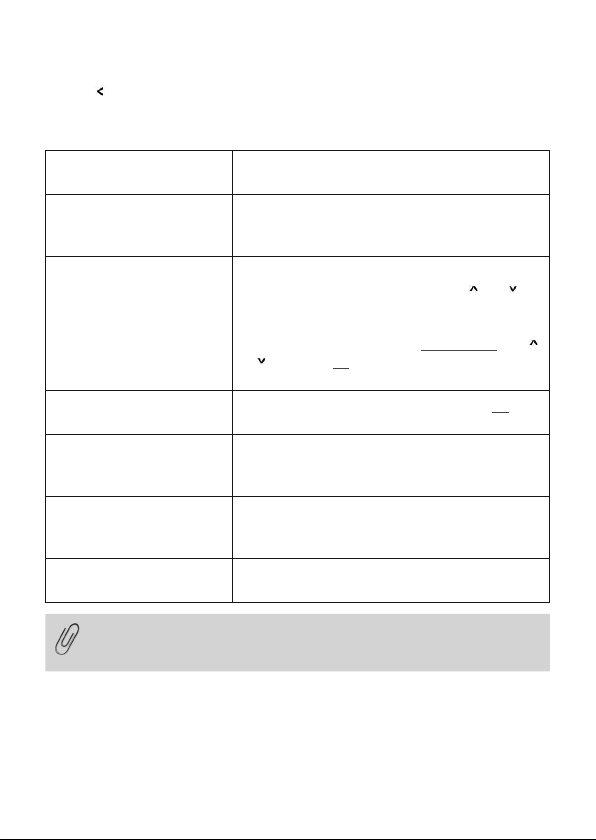
Use the to leave the setup mode.
Advanced Settings mode
Reset to defaults
Reset device
Enter Loader Mode
Enter Test Mode >
Capture Output SLOT1
Capture Output SLOT2
Contrast
<bar line>
If you want to have all fixtures turned off at startup, send a pattern with
all zeroes for all channels to the Butler PRO. Use this pattern as snapshot for startup display to make sure that all fixtures are off.
Resets all parameters, including IP address, to
the default values.
Resets the device and reboots the Butler PRO.
Does not change the parameter settings of the
Butler PRO.
Enters the loader mode and waits for commands,
e. g. to update the firmware. With the
keys you can view the Butler PRO main
parameters and the escape step. To escape and
leave the loader mode, select START APP with
or and press OK. The Butler PRO loads its
firmware now.
Calls the Test Mode command set, Press OK to
enter Test Mode.
Captures the current state as snapshot 1 for
offline or startup display. All Butler PROs with the
same GroupID also capture this state.
Captures the current state as snapshot 2 for
offline or startup display. All Butler PROs with the
same GroupID also capture this state.
Set the contrast of the display.
and
Test mode
In Test Mode you can test all or a single output of the Butler PRO and the connected fixtures. There are three test modes: value, fade and strobe. In value mode
a fixed DMX value is sent to all channels as white value. In fade mode the channels
14
Page 15
Setup Manual - Butler PRO
are faded from zero to a defines value in a loop. In strobe mode all channels get a
square signal to realize a strobe effect.
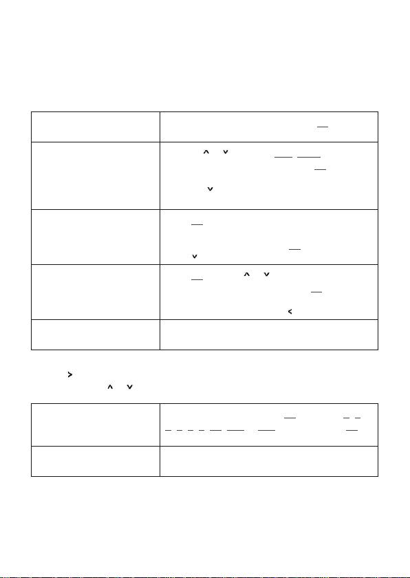
After selecting from the advanced settings you reach level one of the test mode:
select Output
none
select Output
>none
Select the outputs to test. Press the OK key and
select the tested outputs with the next step.
With the or key select all, none or a single
output of the Butler PRO. Press the OK key again
to set the output channel(s) and return.
Press the
to select the maximum brightness in
test mode.
Set Level
255
Press OK, use the cursor keys to select and set
position and value of test brightness. The
maximum value is 255. Press OK to set this value.
to select the test mode.
Press
select Test Mode
value
Press Ok, with the or key select the test
mode: value, fade or strobe. Press OK again to
select the test mode. The test mode runs until
key.
Output Mode
dmx
you leave test mode with the
Select the output mode dmx or epix
Butler PRO e:pix only.
For the test of a subset of fixtures you can select a block size and block move value
key. This submenu is reached in every position of the first level as a
with the
second level. Use
Block size
<value>
or to navigate.
To select a block size, press OK and select 1, 2,
3, 4, 5, 6, 48, 192 or 512 channels. Press OK
again to set the block size (Butler PRO DMX)
Universe size
512 (def DMX)
Select the size of one universe for the Butler PRO
e:pix only.
15
Page 16
Setup Manual - Butler PRO
Block move
>manual
Return from the second level submenu to the first level with the
While the test is running you can switch to a third level menu from the second level
key. In this third level menu the current DMX or e:pix address is
with the
displayed.
Start Address
<value>
Return to the second and first level of the test mode menu with the key.
Pressing
again returns to the Advanced Settings.
To select block move speed, press the OK key.
Select a timing of 50 ms, 100 ms, 500 ms or
1 s for automatic movement. Select manual for
manual stepping through channels. Press OK to
set the block move speed.
key.
In automatic (timed) mode the current DMX start
address of the block. With the
running direction is switch to up or down
direction. Keeping the key pressed a fast change
is possible. With the OK key toggling the test
mode gets paused and restarted again.
In manual mode the start address is stepped up
or down with the
or keys.
and keys
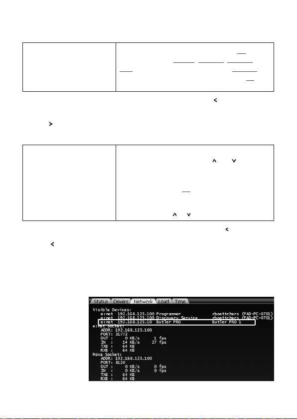
Online configuration
Connect the Butler PRO via a switch to a system running e:cue Lighting Application
Suite; start the Programmer.
Select the Network
tab in the status
window in the
upper left. Any
Butler PRO devices
which are
connected to the
network should
appear in the list. If
they do not show
16
Page 17
Setup Manual - Butler PRO
up in the list, check if the IP address settings for your computer are correct and the
network range is 192.168.123.*, the default address of any new Butler PRO is
192.168.123.1. Please also make sure your fire wall does not prevent communication between the computer and the Butler PRO. The Butler PRO should become
visible.
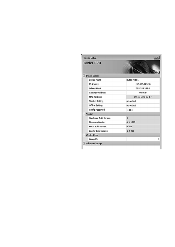
Click on the Butler PRO line in the
Network display, this opens the
device configuration dialog. Here
you can set all driver properties of
the Butler PRO. The IP address
typically this
should read 192.168.123.1 at this
stage, when the Butler PRO is still
set to factory defaults.
y Assign a new IP address e.g.
192.168.123.200.
y Use the same procedure for
the remaining network parameters: Subnet Mask - usually
255.255.255.0, Gateway – no
gateway
y Give the Butler PRO a unique
name.
y Apply the changes with the Ok button
The parameters to configure in online mode are the same as configuring the Butler
PRO manually. Additionally a new password may be set and the DMX parameters
can be changed. Parameters in grey are read-only and cannot be changed, like the
MAC address or the version numbers. If the password is omitted, the setup will not
be protected.
17
Page 18

Setup Manual - Butler PRO
Network parameters
Device Basics
Device Name The device will be displayed with this name in the e:cue
IP address The IP address of the device (default: 192.168.123.1)
Subnet Mask The netmask of the device (Default: 255.255.255.0)
Gateway address The default gateway of the device (Default: no gateway)
MAC address The physical address of the device (read only)
Startup Setting The snapshot to be used in startup phase or none.
Offline Setting The snapshot to be used in offline phase or none.
Config Password The password to enter manual configuration mode.
Versions
Hardware Build Version The hardware version (read only).
Firmware Build Version The software version (read only).
FPGA Build Version The command set for the internal FPGA (read only).
Loader Build Version The version of the rmware loader.
Cluster Mode
Group ID The cluster ID of this Butler PRO.
Advanced Setup (do not modify unless instructed so)
Lock Settings Checkmark, set by default, avoids changes for
BRK Length Break signal length in µs for the DMX/e:pix protocol.
MAB Length Mark after break length in µs for the DMX/e:pix
BRK Length RDM Break length in µs for the RDM protocol
MAB Length RDM Mark after break length in µs for the RDM protocol
RDM Switch Time The RDM Tx to Rx length in in µs
programmer.
DMX/e:pix and RDM by chance.
protocol.
(Butler PRO DMX only).
(Butler PRO DMX only).
(Butler PRO DMX only).
18
Page 19
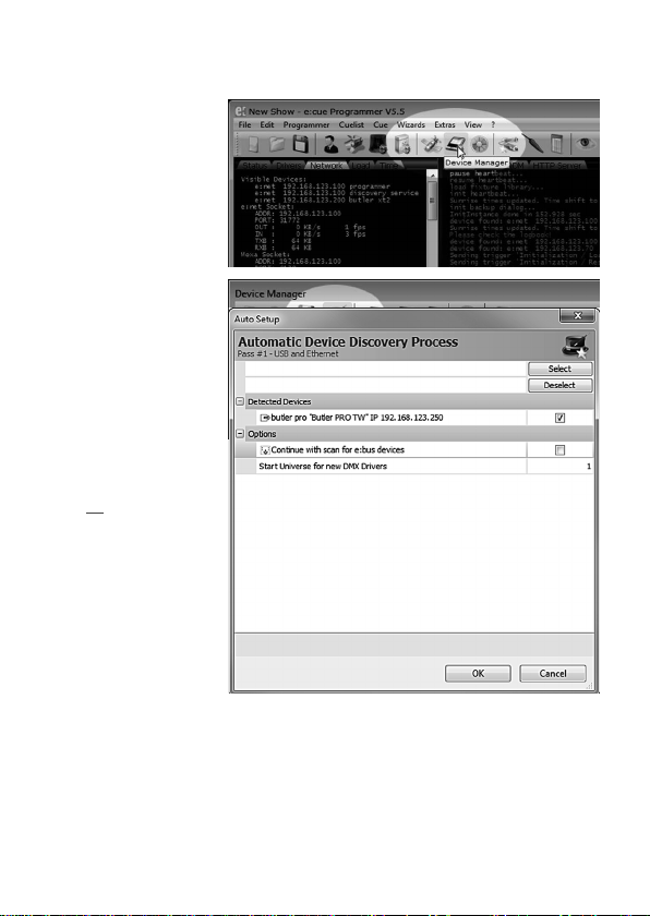
To add the Butler PRO to
the Programmer
configuration start the
Device Manager.
Execute the Automatic
Setup Wizard. The Butler
PRO will be found and
displayed:
Set the checkmark for
the Butler PRO to add it
to your setup or click the
Select button. To set the
driver properties for the
Butler PRO double-click
the Butler PRO in den
device overview of the
Device Manager.
Click Ok to add the
Butler PRO to the Programmer configuration,
the Butler PRO is now
available.
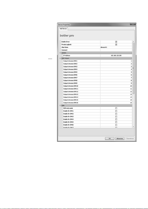
Double-click the new
Butler PRO in the
Device Manager and an
additional configuration
dialog gets displayed to
set more parameters for
the Butler PRO.
Setup Manual - Butler PRO
19
Page 20
Setup Manual - Butler PRO
Using this device setup
dialog you can set the DMX
universes as well as the
required RDM feedbacks for
the channels of the Butler
PRO.
When finished close the device setup dialogue with Ok.
Connecting more than one Butler PRO
In case you have several Butlers PRO they need to be configured one at a time. Do
not connect all of them to the network immediately! This is due to the fact that the
devices all come with the same IP address by factory default. If they are connected
simultaneously an IP address conflict will occur and configuration is not possible. Instead, connect the Butlers PRO one at a time. Connect the first Butler PRO and assign a new IP address to the device (e. g. 192.168.123.11). Repeat this sequence
until all devices have been assigned with an individual IP address. In a next step all
devices can be hooked up to the connecting network.
20
Page 21
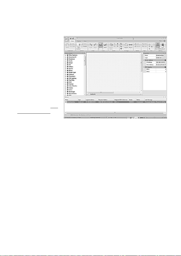
Firmware update
To update the firmware
of the Butler PRO
proceed the following
way:
y Start the Patchelor of
the e:cue Lighting Application Suite
y In the list of found
devices select the appropriate Butler PRO.
y Press the right mouse
button and select Up-
date Firmware.
y Select the file with the
new firmware (*.bxt).
y After the download is complete the Butler PRO will restart.
y The new firmware is available now.
Setup Manual - Butler PRO
21
Page 22

Setup Manual - Butler PRO
Troubleshooting
Problem Check Reason See also
The Butler PRO
does not go online
in the Programmer/Patchelor
Does the LAS
server have a fixed
network address?
Is a correct IP
address assigned?
Are Butler PRO
and LAS server in
the subnet?
Is the network
adapter in the
LAS server and in
the Programmer/
Patchelor Network
Card configured
correctly?
More than one
Butler PRO with
the same IP Address?
Is there a
direct connection between the
LAS server and
the Butler PRO
without a Ethernet
switch?
The Butler PRO
must be in the
same IP subnet
as the Computer. Example:
192.168.123.xxx
The e:net interface
IP address must
be assigned in
the Programmer/
Patchelor.
Factory default of
Traxon products is
IP: 192.168.123.1
Some network
adapters do not
support a direct
connection. Use
an Ethernet switch
in any case.
Setup Manual
LAS Setup Manual
Setup Manual
Setup Manual
22
Page 23

Setup Manual - Butler PRO
RDM without
function
Is RDM enabled in
the Programmer’s
Device Manager for the Butler
PRO?
RDM “Enable for
DMX 1 to 16”
must be activated in the Device
Properties in the
Programmer for
this Butler PRO.
LAS Setup Manual
23
Page 24

Technical specifications
The Butler PRO is certied according to
EN 55022, EN 55024, EN/UL 60950
General specifications
Dimensions 482 x 44 x 142 mm
(W x H x D) (incl. mounting brackets)
Weight 1200 g
Power 100 ... 240 V AC, 50/60 Hz
Power consumption 20 W
Operating/storage temp. 0 … 40 °C/32 … 104 °F
Operating/storage hum. 0 … 80%, non-condensing
Protection class IP20
Housing Aluminium, polyamide 6.6
Mounting 19-inch rack mounting, wall mounting
Engine specifications
User interface 4 cursor keys, OK key
System links 1 x e:net (RJ45 Ethernet)
16 x DMX (RJ45) or 16 x e:pix
Display 2-lines, 40 characters/line display
Data storage micro SD card, internal
e:net specifications
Connection RJ45, 8P8C
Speed 100 MBit/s
POE capability no
C
Page 25

Setup Manual - Butler PRO
DMX output specification
Number of outputs 16 DMX universes, 8,192 channels
Short circuit protection yes, reversible
DMX operation USITT DMX512-A,
RDM ANSI E1.20,
Connectors RJ45 receptacle connector,
Traxon pin configuration
e:pix output specification
Number of outputs 16 e:pix universes, 32,768 channels
Short circuit protection yes, reversible
e:pix Traxon standard
Connectors RJ45 receptacle connector,
Traxon pin configuration
25
Page 26

Setup Manual - Butler PRO
Deutsch
26
Page 27
Setup Manual - Butler PRO
!
!
!
!
!
!
Sicherheitshinweise
Das Produkt darf nur von einer Elektrofachkraft installiert und in Betrieb
genommen werden. Die geltenden Sicherheits- und Unfallverhütungsvorschriften sind zu beachten.
Arbeiten an dem Produkt nur im spannungsfreien Zustand durchführen.
Anderenfalls kann zu elektrischen Schocks kommen oder das Gerät wird
beschädigt.
Netzwerk, DMX oder andere Kommunikationsleitungen nicht zusammen
mit Netzleitung verlegen. Die Datenkommunikation kann gestört werden
oder Funktionen des Gerätes werden eingeschränkt.
Das Produkt darf nur mit den in der Anleitung aufgeführten Betriebsarten
betrieben werden. Alle anderen Anwendungen gelten als sachwidrig.
Wird das Produkt nicht bestimmungsgemäß verwendet, ist kein sicherer
Betrieb gewährleistet. Schäden oder Störungen können die Folge sein.
Um ein Überhitzen des Gerätes zu verhindern, darf es nur in gut
belüfteten Umgebungen betrieben werden. Lüftungsschlitze dürfen nicht
abgedeckt werden. Durch Überhitzung wird das Gerät beschädigt.
Das Gerät oder Teile des Gerätes können im Betrieb heiß werden. Zur
Montage oder Demontage das Gerät ausreichend abkühlen lassen um
Verbrennungen zu vermeiden.
Reparaturen am Gerät dürfen nur von geschultem oder ausgebildeten
Personal vorgenommen werden. Im Zweifelsfall kontaktieren Sie e:cue.
Fehlerhafte Reparaturen können das Gerät beschädigen.
Bei Montage mit Festanschluss der Netzversorgung muss außerhalb der
Einrichtung eine leicht zugängliche Trennvorrichtung vorhanden sein. Bei
Montage mit Steckanschluss muss die Steckdose nahe der Einrichtung
angebracht und leicht zugänglich sein, damit das Gerät zur Montage
stromlos gesetzt werden kann.
27
Page 28
Setup Manual - Butler PRO
DMX512/RDM or e:pix
DMX512/RDM or e:pix
DMX512/RDM or e:pix
Gerätebeschreibung
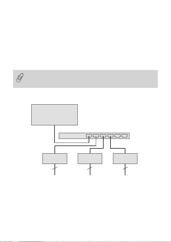
Der Butler PRO ist ein 16 Kanal-DMX/RDM- oder e:pix Interface für einen Server
mit der e:cue Lighting Application Suite und Systemen mit DMX512- oder e:pixVerbindungen. Üblicherweise wird der Butler PRO in einen 19-Zoll-Rack installiert
Die Verbindung zum Server wird mit Standard-CAT5-RJ45 Ethernetkabeln hergestellt. Auch der DMX-Anschluss ist als RJ45 ausgeführt. Alle handelsüblichen CAT5RJ45-Kabel können benutzt werden.
Bitte beachten Sie, das e:net einen isoliertes Netzwerk benötigt. Es
arbeitet nur unzureichend in Netzen, in denen gleichzeitig Audio- oder
Video-Streaming betrieben wird!
Systemdiagram
e:cue LAS
Ethernet switch
Butler PRO Butler PRO Butler PRO
16 x output channels
16 x output channels
16 x output channels
Benutzen Sie übliche CAT5-RJ45-Ethernetkabel für die Verbindung von Server,
Switch und Butler PRO. Die Verbindung ohne einen Ethernet-Switch mit einem
Ethernet-Crosskabel wird nicht empfohlen. Um DMX-Systeme mit einem XLR5Stecker anzuschließen, ist ein entsprechender Adapter unter der Bestellnummer
40005 verfügbar. Sprechen Sie Ihren e:cue-Distributor dazu an.
28
Page 29
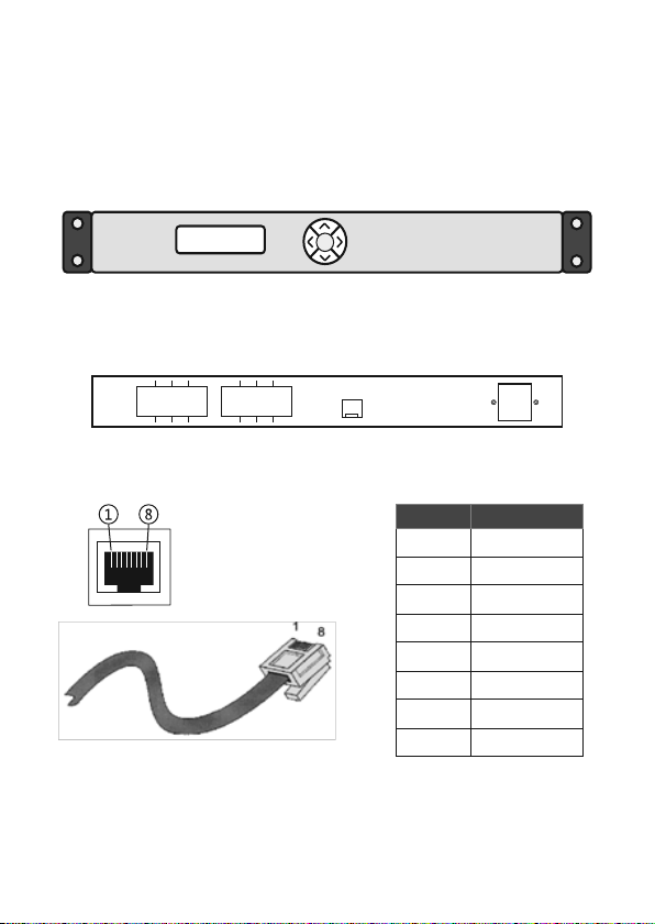
Anschlüsse
Systemanzeige
Cursor-Tasten
OK-Taste (Mitte)
OK
Status >
online DMX 35Fps
Ethernet/e:net Netz
Frontplatte
Rückseite
Ausgänge 1 ... 16
1 3 5 7
2 4 5 6
Pin-Belegung
9 11 13 15
10 12 14 16
Setup Manual - Butler PRO
Ethernet
pin no. signal
1 DMX-/e:pix-
2 DMX+/e:pix+
3 Masse
4 n. v.
5 n. v.
6 n. v.
7 n. v.
8 n. v.
29
Page 30
Setup Manual - Butler PRO
Montage
Montieren Sie den Butler PRO in einem 19-Zoll-Rack. Benutzen Sie passende
Rackschrauben, Käfigmuttern und Scheiben zur Montage.
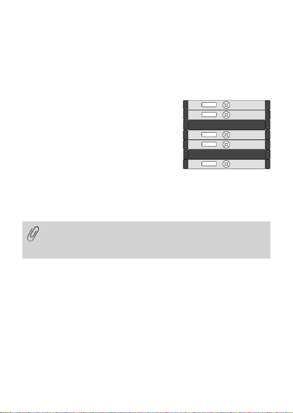
Platzierung im Rack
Da der Butler PRO keine aktive Kühlung besitzt, positionieren Sie maximal zwei Systeme übereinander,
lassen eine Höheneinheit frei oder belegen sie mit
einem passiven Gerät. Achten Sie insbesondere auf:
y mit Rackblenden verschlossenen freie Einheiten
y auf Montage in einem geschlossenen Rack mit
Kühlung durch einen Rack-Lüfter
y Unterbringung des Racks in einem klimatisiertem
Raum
Verbinden Sie den Butler PRO mit einem Ausgang eines Ethernet-Switch und mit
Netzspannung.
Wenn mehr als ein Butler PRO im Auslieferungszustand installiert
werden, muss gewährleistet sein, dass nur ein Butler PRO zu einer Zeit
im Netz ist. Die Verbindung von mehreren Butler PRO mit gleicher IPAdresse (192.168.123.1) wird die Ethernet-Verbindung stören.
Benutzeroberfläche
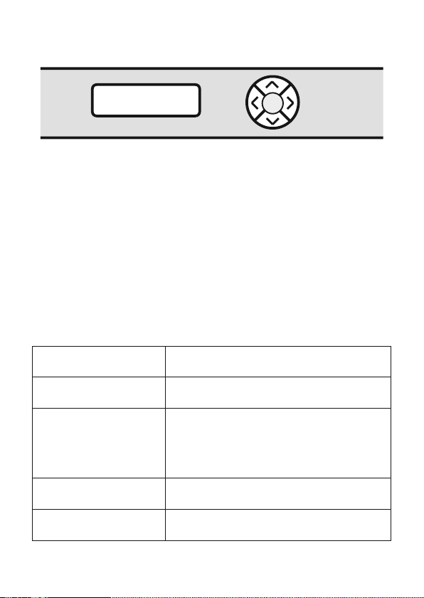
Die Benutzeroberfläche des Butler Pro besteht aus eine Cursortasten mit zentraler
OK-Taste und einem LC-Display. Damit sind Betrieb und Einrichtung möglich.
Während des regulären Betriebes zeigt der Butler PRO Systeminformationen oder
Meldungen an. Bei der Einrichtung werden Parameter und Werte angezeigt Der
Tastenkranz dient zur Auswahl von Parameters und Eingabe von Werten. Nur die
Tasten, die in einem bestimmten Eingabezustand erlaubt sind, sind beleuchtet. Dies
gilt für Normalbetrieb und Einrichtung.
30
Page 31
Setup Manual - Butler PRO
Cursor keys
OK key (center)
Status >
online DMX 35Fps
Nach Inbetriebnahme des Butler PRO zeigt der Loader den Ladevorgang an,
ebenso die Versionen des Loaders und der Firmware. Nach dem Laden geht der
Butler PRO in den Normalbetrieb. Der Einrichtungsmodus (Setup) muss getrennt
gestartet werden. Die Bedienung erfolgt in Englisch.
Ist der Butler PRO online, werden IP-Adressen und Netzparameter angezeigt. Ebenso die Adresse des Servers mit der Lighting Application Suite. Alle hier gezeigten
Werte sind Beispiele. Sie hängen von der Konfiguration des Butler PRO und vom
Netzwerk ab.
OK
Betriebsanzeigen
Nach Inbetriebnahme und Laden durchläuft der Butler PRO einen Satz von Standardanzeigen. Dabei steht DEVICENAME für den Systemnamen, der entweder in
der Online- oder manuellen Konfiguration vergeben wurde. :
Butler PRO <DMX>
©2013 traxon/ecue
Butler PRO <EPIX>
©2013 traxon/ecue
*** ERROR ***
no snapshot found
DEVICENAME
<offline>
DEVICENAME
no output
Startanzeige des Butler PRO DMX.
Startanzeige des Butler PRO e:pix.
Nach dem Laden ist der Butler PRO offline (keine
Verbindung zum LAS-Server) und es wurde kein
Standbild für den Offline-Status gespeichert.
Drücken Sie die OK-Taste um die Meldung zu
löschen.
Der Butler PRO hat keine Verbindung zu einem
LAS-Server und ist offline.
Der Butler PRO ist offline und sendet keine Daten
(kein Standbild) im Offline-Status.
31
Page 32
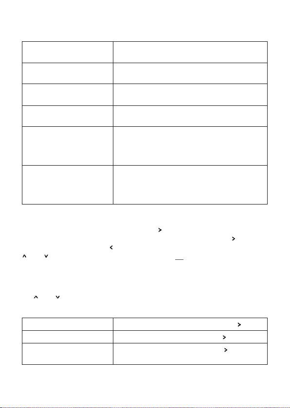
Setup Manual - Butler PRO
DEVICENAME
IP: 192.168.123.123
DEVICENAME
MASK: 255.255.255.0
DEVICENAME
<online>
DEVICENAME
Mode: DMX 35 Fps
DEVICENAME
Connected to:
DEVICENAME
192.168.123.100
*** WARNING ***
temperature high!
Die IP-Adresse des Butler PRO.
Die Netmask für die IP-Verbindung. Standard ist
255.255.255.0
Der Butler PRO ist online und mit einem LASServer verbunden.
Der Butler PRO ist im DMX-Modus, die maximale
Bildrate beträgt 35 fps
Die IP-Adresse des LAS-Servers, mit dem der
Butler PRO verbunden ist.
Der Butler PRO hat die zulässige Maximaltemperatur überschritten. Schalten Sie das Gerät zum
Abkühlen aus und beachten Sie die Montagehinweise in diesem Manual.
Nutzen der Anzeige und des Tastenkranzes
Anzeigen mit einem rechten spitzen Klammer ( ) sind Meldungen. Anzeigen mit
einer solchen Klammer sind Einstiege in Untermenues. Drücken Sie die
Untermenues aufzurufen. Die
- und -Tasten werden Parameter ausgewählt. Mit OK werden Einstellungen oder
Auswahlen bestätigt. Nur erlaubte Tasten sind beleuchtet.
-Taste führt aus dem Untermenue zurück. Mit den
-Taste um
Parameter-Einstellungen
Die - und -Tasten im Hauptmenue führen durch die Einträge dieser obersten
Ebene.
Device Info >
Setup >
Status >
online DMX 35 Fps
Einstieg in den Device Info Mode mit der -Taste.
Einstieg in den Setup Mode mit der -Taste.
Einstieg in den Status Mode mit der -Taste für
Butler PRO DMX.
32
Page 33
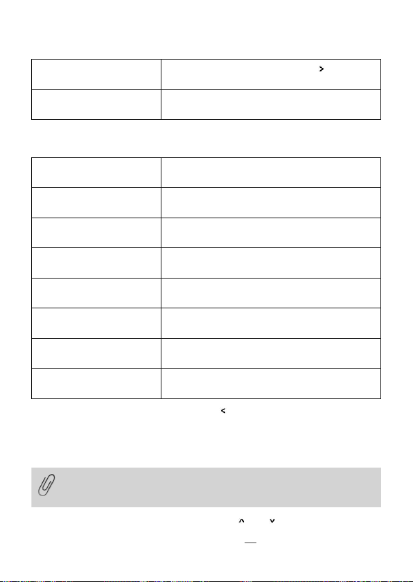
Setup Manual - Butler PRO
Status >
online EPIX 31 Fps
DEVICENAME
<online>
Einstieg in den Status Mode mit der
Butler PRO e:pix.
Zurück in der Standard-Anzeige.
Device Info-Modus
Info IP
192.168.123.250
Info MAC
00:16:1c:f1:17:b7
Info FW Version
1.0.123
Info FPGA Version
1.0.1
Info HW rev.
1
Info Keypad Version
1.0.5
Info connected to
192.168.123.100
Info temperature
37 C
Verlassen Sie den Device Info Modus mit der
TDie IP-Adresse dieses Butler PRO.
Die MAC-Adresse dieses Butler PRO.
Die installierte Firmware-Version.
Die installierte FPGA-Version.
Die Hardware-Version dieses PRO.
Die Firmware-Version des Tasten-Controllers.
Die IP-Adresse des LAS-Servers.
Die interne Temperatur dieses Butler PRO in Grad
Celsius.
-Taste.
Grundeinstellungen
Auswählen und Ändern von Parametern
Im Auslieferungstand ist der Setup-Modus durch ein Passwort geschützt. Dieses Passwort lautet “ecue”. Das Passwort kann im OnlineBetrieb gelöscht oder geändert werden.
y Wechseln Sie zwischen den Parameter mit den - und -Tasten.
y Wählen Sie den zu ändernden Parameter mit der OK-Taste.
-Taste für
33
Page 34
Setup Manual - Butler PRO
y Drücken Sie die - und -Tasten um die zu ändernde Position zu wählen.
y Drücken Sie die - und -Tasten um den Wert zu ändern. Halten Sie die Taste
gedrückt um den Wert schneller zu ändern.
y Bewegen Sie den Cursor ganz nach rechts. Wählen Sie das Kreuz um die Änder-
ung abzubrechen oder das Häkchen zur Bestätigung. Drücken Sie die OK-Taste.
y Für den Systemnamen drücken Sie die OK-Taste um die Änderung zu beginnen.
Wählen Sie Position und Wert wie zuvor.
Mit der OK-Taste gelangen Sie wieder in die Bestätigung in der oberen Reihe.
Wählen Sie mit der
- oder -Taste die Bestätigung, den Abbruch oder über den
Rückwärts-Pfeil das Löschen von Zeichen. Drücken Sie wieder die OK-Taste.
Mit dem Eintrag Advanced settings > wird ein weiteres Untermenue mit
speziellen Funktionen erreicht. Mit der
-Taste kann dieses und jedes andere
Menue verlassen werden. Ein weiteres Untermenue in den Grundeinstellungen ist
der Test Modus. Dieser wird bei der Anzeige von Enter Test Mode > erreicht.
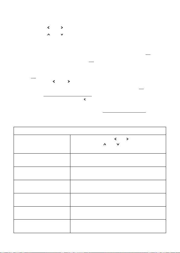
Grundparameter und Werte (Setup)
Standard-Parameter
enter Password
Setup IP
192.168.123.200
Setup Subnet Mask
255.255.255.000
Setup Gateway
192.168.123.001
Setup NAME
Butler PRO
Setup GROUPID
001
Setup STARTUP
show snapshot1
34
Mit den Cursor-Tasten
Position und mit
Sie OK um das Passwort abzuschließen.
Die IP-Adresse des Butler PRO. Auslieferungszustand ist 192.168.123.1
The Subnetz-Maske. Auslieferungszustand ist
255.255.255.0
Das Netzwerk-Gateway. Wird kein Gateway
benutzt, setzen den Wert auf 0.0.0.0
Der Systemname.
Die Group id für die Synchronisation der Aufnahmen von Standbildern über mehrere Butler PRO.
Das Standbild für den Systemstart, snapshot 1,
snapshot 2 oder no output (keine Anzeige).
und wählen Sie die
oder die Zeichen. Drücken
Page 35
Setup Manual - Butler PRO
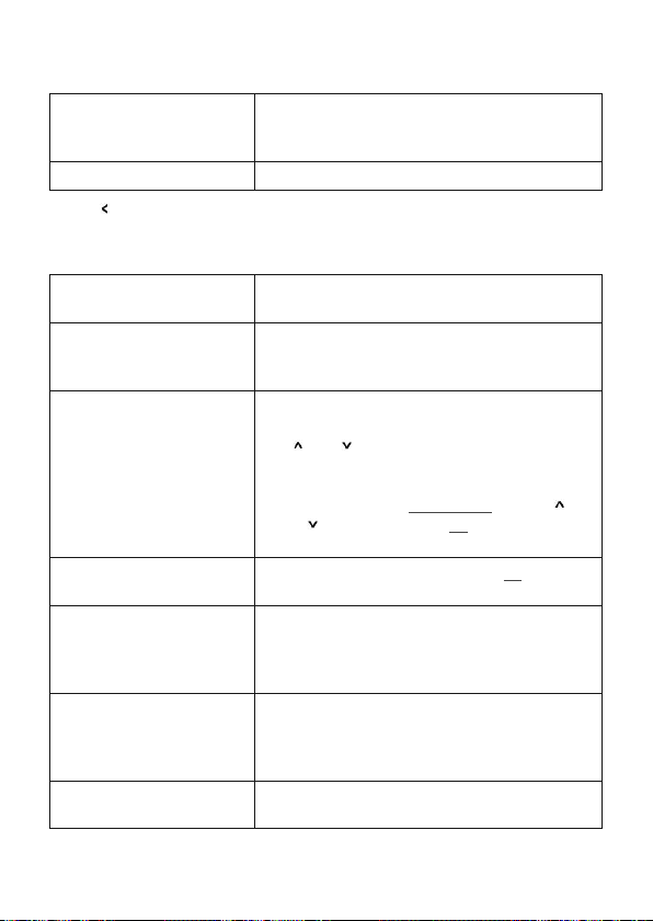
Setup OFFLINE
show snapshot2
Das Standbild für den Offline-Zustand des Butler
PRO, snapshot 1, snapshot 2 oder no output
(keine Anzeige).
Advanced settings >
Mit der
-Taste kann der Setup Modus verlassen werden.
Einstieg in die erweiterten Einstellungen.
Erweiterte Einstellungen (Advanced Settings)
Reset to defaults
Reset device
Enter Loader Mode
Enter Test Mode >
Capture Output SLOT1
Capture Output SLOT2
Contrast
<bar line>
Setzt alle Systemparameter auf den Auslieferungszustand zurück, einschließlich IP-Adresse.
Setzt das System zurück und startet den Butler
PRO neu. Es werden keine Systemparameter
verändert.
Startet den Loader-Modus und wartet auf weitere
Befehle, zum Beispiel zum Firmware-Update. Mit
- und -Tasten können immer noch die
den
wichtigsten Systemparameter angezeigt werden.
Um den Loader-Modus abzubrechen zu
verlassen, wählen Sie START APP über die
- oder -Taste und drücken OK. Der Butler PRO
lädt nun seine Firmware.
Wählt den Test Modus. Drücken Sie OK um den
Test Modus zu starten.
Speichert den aktuellen Zustand an den Ausgängen des Butler PRO als Standbild1 (snapshot1).
Alle Butler PRO mit gleicher GroupID speichern
ebenso den aktuellen Zustand.
Speichert den aktuellen Ausgabezustand als
Standbild2 (snapshot2). Alle Butler PRO mit
gleicher GroupID speichern ebenso den aktuellen
Zustand.
Einstellen des Kontrastes der Anzeige.
35
Page 36
Setup Manual - Butler PRO
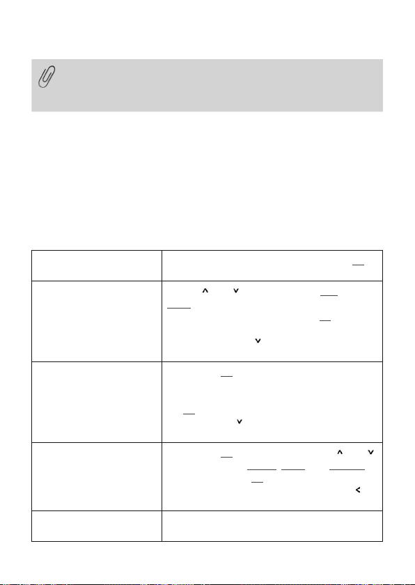
Um beim Systemstart alle Leuchten zuverlässig dunkel zu schalten,
senden Sie ein Muster mit nur DMX-Werten = Null an die Ausgänge.
Speichern Sie diesen Zustand als Standbild und nutzen Sie ihn als
Standbild für den Systemstart.
Test-Modus (Test mode)
Im Test Modus können Sie alle oder einzelne Ausgänge des Butler PRO wie auch
Leuchten überprüfen. Es gibt drei Testarten: value (Wert), fade (Blenden) und strobe
(Blinken). Im Value-Modus wird ein fester DMX-Wert an die Leuchten geschickt. Im
Fade-Modus werden die Leuchten fortlaufend von Null auf einen eingestellten Wert
auf- und abgeblendet. Im Strobe-Modus werden die Lampen zwischen Null und
dem eingestellten Wert umgeschaltet.
Nach Auswahl aus den Advanced Settings wird der Test-Modus erreicht:
select Output
none
select Output
>none
Set Level
255
select Test Mode
value
Output Mode
dmx
36
Die zu testenden Augänge. Drücken Sie die OKTaste für den nächsten Schritt.
Mit den - und -Tasten wählen Sie all (alle),
none (keinen) oder einen einzelnen Ausgang des
Butler PRO. Drücken Sie wieder die OK-Taste für
die Bestätigung der Auswahl.
Drücken Sie nun die
-Taste um die maximale
Helligkeit einzustellen.
Drücken Sie OK, wählen Sie für den Wert der
DMX-Ausgabe mit den Cursor-Tasten Position
und Wert aus. Der Maximalwert ist 255. Drücken
Sie OK um den Wert zu speichern.
Drücken Sie die
-Taste um den Test-Modus zu
starten.
Drücken Sie Ok und wählen Sie mit den - und
-Tasten die Testart value, fade oder strobe.
Drücken Sie wieder OK um die Testart zu
bestätigen. Der Test läuft nun bis Sie mit der
-Teste den Test verlassen.
Ausgabemodus DMX oder e:pix (nur für den
Butler PRO e:pix).
Page 37
Setup Manual - Butler PRO
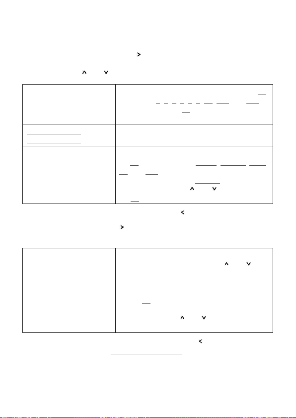
Für den Test ausgewählter Lampen kann eine Blockgröße (block size) und eine
Geschwindigkeit (block move) mit der
-Taste gewählt werden. Dieses weitere
Submenue ist über jeden Eintrag der zweiten Ebene verfügbar. Wählen Sie den
Parameter über die
Block size
<value>
oder -Taste.
Um eine Blockgröße einzustellen, drücken Sie OK
und wählen 1, 2, 3, 4, 5, 6, 48, 192 oder 512
Kanäle. Drücken Sie OK um die Blockgröße zu
wählen.
Universe size
512 (def DMX)
Block move
>manual
Größe des Ausgabe-Universums
(nur Butler PRO e:pix)
Um die Geschwindigkeit einzustellen, drücken Sie
die OK-Taste. Wählen Sie 50 ms, 100 ms, 500
ms oder 1 s für das automatische Weiterschalten
des Blockes. Wählen Sie manual für manuelles
Weiterschalten mit den
- und -Tasten. Drücken
Sie OK um die Geschwindigkeit zu bestätigen.
Für die Rückkehr zur zweiten Ebene drücken Sie die
Während der Test läuft, führt die
-Taste in einen weiteren dritten Level. Hier wird
-Taste.
die aktuelle DMX/e:pix-Startadresse angezeigt.
Start Address
<value>
Im automatischen Betrieb ist dies die aktuelle
Startadresse des Blockes. Mit den
- und
-Tasten kann die Laufrichtung umgeschaltet
werden. Auch hier ist durch Gedrückthalten der
Taste eine schnelle Änderung möglich.
Mit der OK-Taste kann der Testlauf angehalten
und wieder gestartet werden. Im manuellen
Modus schalten die
oder -Tasten die
Blockadresse aufwärts oder abwärts.
Die Rückkehr zur zweiten Ebene des Tests erfolgt über die
-Taste. Ein weiteres
Drücken führt auf das Menue Advanced Settings zurück.
37
Page 38
Setup Manual - Butler PRO
Online-Konfiguration
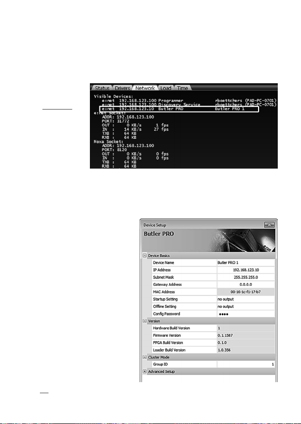
Verbinden Sie den Butler PRO über einen Ethernet-Switch mit einem System, auf
dem die Lighting Application Suite (LAS) installiert ist. Starten Sie den Programmer.
Wählen die im linken
obenen Fenster den
Reiter Network.
Der Butler PRO
sollte dort sichtbar
sein. Wird der
Butler PRO nicht
angezeigt, prüfen
Sie die IP-Adresse
und die weiteren
Netzwerk-Parameter des LAS-Systems, sie sollte im Bereich 192.168.123.*, die Standard-Adresse
des Butler PRO im Auslieferungszustand 92.168.123.1. Stellen Sie ebenso sicher,
dass die Verbindung nicht durch eine Firewall verhindert wird.
Clocken Sie auf die Butler PROZeile in der Netzwerk-Ansicht und
es öffnet sich ein KonfigurationsDialog. Hier können alle Parameter
des Butler PRO eingestellt werden.
Die IP-Adresse des Butler PRO
sollte typischerweise 192.168.123.1
lauten, wenn es sich um einen
neuen Butler PRO handelt.
y Weisen Sie eine neue, en-
deutige IP-Adresse zu, z. B.
192.168.123.200.
y Als Netzwerkmaske (netmask), ist
255.255.255.0, kein Gateway.
y Geben Sie dem Butler PRO einen
eindeutigen, sprechenden Namen.
y Bestätigen Sie die Einstellungen
mit Ok.
38
Page 39

Setup Manual - Butler PRO
Die Parameter, die im Online-Modus gesetzt werden, sind die gleiche wie die bei
manueller Konfiguration offline. Zusätzlich kann ein Passwort für den Setup-Modus
gesetzt oder gelöscht werden. Parameter in Grau sind nur Anzeigen und können
nicht verändert werden, wie die MAC-Adresse oder Versionsangaben. Wird das
Passwort gelöscht, ist der Setup-Modus nicht mehr geschützt.
Netzwerk-Parameter
Device Basics
Device Name Der Name des Gerätes in den Anzeigen
IP address Die IP-Adresse
(Standard: 192.168.123.1)
Subnet Mask Die Netzmaske des Systems
(Standard: 255.255.255.0)
Gateway address Das Gateway für die Netzverbindung
(Standard: kein Gateway)
MAC address Die physikalische Adresse des Systems (nur lesen).
Startup Setting Das Standbild für die Startphase oder keins.
Offline Setting Das Standbild für den Offline-Zustand oder keins.
Config Password Das Passwort für den Setup-Modus. (Standard: ecue)
Versions
Hardware Build Version Die Hardware-Version (nur lesen).
Firmware Build Version Die Firmware-Version (nur lesen).
FPGA Build Version Die FPGA-Version (nur lesen).
Loader Build Version Die Version des Firmware-Loaders (nur lesen).
Cluster Mode
Group ID Die GroupID für Standbilder (snapshots).
Advanced Setup (sollten nicht geändert werden)
Lock Settings Sperrt die unbeabsichtigten Veränderungen von DMX-
und RDM-Einstellungen.
BRK Length Break-Signallänge in µs für das DMX/e:pix-Protocol.
MAB Length Mark-After-Break-Länge in µs für das DMX/e:pix-
Protocol.
BRK Length RDM Break-Signallänge in µs für das RDM-Protocol
(nur Butler PRO DMX).
MAB Length RDM Mark-After-Break-Länge in µs für das RDM-Protocol
(nur Butler PRO DMX).
RDM Switch Time Die RDM Tx-zu-Rx-Länge in µs (nur Butler PRO DMX).
39
Page 40
Setup Manual - Butler PRO
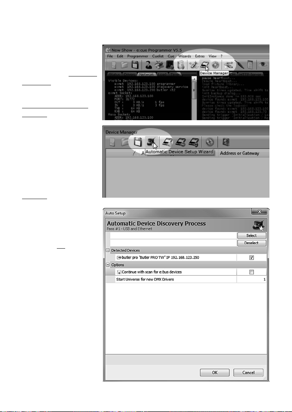
Um den Butler PRO
der Programmer-Konfiguration hinzuzufügen,
starten Sie den Device
Manager.
Führen Sie den
Automatic Setup
Wizard aus. Der Butler
PRO wird gefunden und
angezeigt.
Setzen Sie das Häkchen
am Butler PRO um ihn
der Konfiguration hinzu
zu fügen oder clicken sie
Select. Um die
Treiber-Eigenschaften zu
setzen, doppel-clicken
Sie den Butler PRO im
Device Manager.
Clicken Sie Ok um den
Butler PRO in die Konfiguration einzufügen. Der
Butler PRO ist nun als
DMX-Gerät verfügbar.
Doppel-clicken Sie den
neuen Butler PRO im
Device Manager und ein
weiterer KonfigurationsDialog für den Butler
PRO wird angezeigt.
40
Page 41
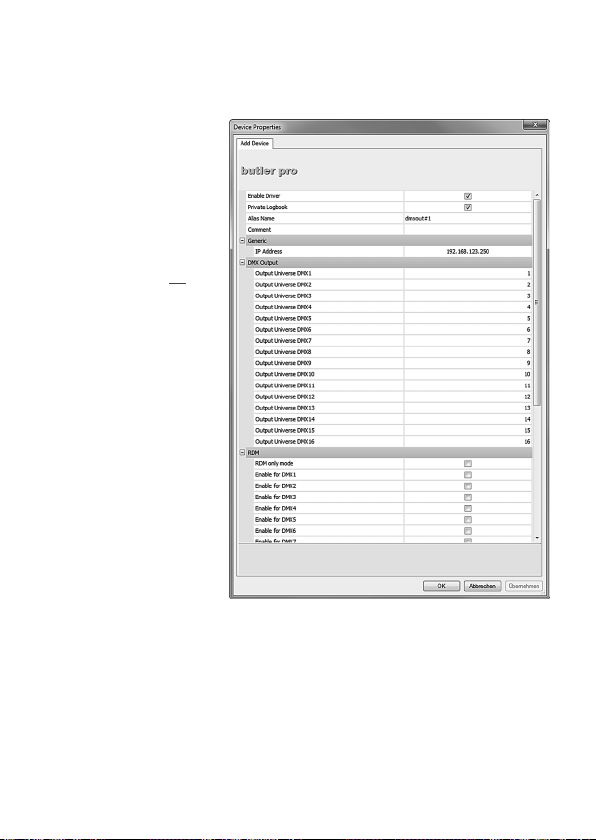
In diesem Dialog können Sie
die zugeordneten
DMX-Universen festlegen
sowie die RDM-Zuordnungen für alle Kanäle des
Butler PRO bestimmen.
Nach Ende dieser Konfiguration verlassen Sie den
Device Manager mit Ok.
Setup Manual - Butler PRO
Anschluss mehrerer Butler PRO
Falls Sie mehrere Butler PRO installieren wollen, müssen diese Einer nach dem Anderen konfiguriert werden. Verbinden Sie nicht alle zugleich mit dem Netzwerk! Im
Auslieferungszustand haben alle Systeme die gleiche IP-Adresse (192.168.123.1).
Werden alle Butler PRO zugleich an das Netzwerk angeschlossen, kommt es zu
Adresskonflikten, die Systeme sind nicht erreichbar oder das gesamte Netz wird
gestört. Schließen Sie stattdessen immer nur einen Butler PRO an das Netz an,
weisen ihm eine eindeutige IP-Adresse zu und wiederholen diesen Vorgang für alle
41
Page 42
Setup Manual - Butler PRO
weiteren Butler PRO. Oder weisen Sie Adressen über den manuellen Setup zu.
Firmware-Update
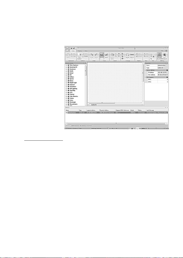
Um den Utler PRO mit
einer neuen Firmware
aufzurüsten, gehen Sie
wie folgt vor:
y Starten Sie den
Patchelor der e:cue
Lighting Application
Suite.
y In der Liste der
vorgefundenen Geräte
Clicken Sie auf den
Butler PRO.
y Drücken Sie die rechte
Maus-Taste über dem
Butler PRO und wählen
Sie Update Firmware.
y Im Dateidialog suchen Sie den neuen Firmware-Stand (*.bxt).
y Nach dem Download auf den Butler PRO started dieser neu.
y Der neue Firmware-Stand ist nun verfügbar.
42
Page 43

Setup Manual - Butler PRO
Fehlerbehebung
Problem Zu prüfen Grund Siehe auch
Der Butler PRO
geht im Programmer oder Patchelor nicht online.
RDM ohne Funktion.
Hat der LASServer eine
feste IP-Adresse?
Ist die korrekte IP-Adresse
zuge-wiesen?
Netzmake?
Ist der Netzwerkanschluss im
LAS-Server und
im Programmer/
Patchelor richtig
eingestellt?
Mehr als ein Butler
PRO mit gleicher
IP-Adresse?
Sind LAS-Server
und Butler PRO
ohne EthernetSwitch direkt
verbunden?
Ist RDM im Device
Manager des
Programmers
freigegeben?
Der Butler PRO
muss im gleichen
Subnetz arbeiten
wie der LASServer. Z. B.:
192.168.123.xxx
Im Programmer/
Patchelor muss
der richtige Netzwerkanschluss
eingestellt sein.
Der AuslieferungsStandard ist immer
192.168.123.1
Nicht alle
Netzwerk-Adapter
unterstützen eine
direkte Verbindung. Nutzen
Sie immer einen
Ethernet-Switch
zur Verbindung.
RDM “Enable for
DMX 1 to 16”
muss in den Geräteeigenschaften
im Programmer für
den Butler PRO
freigegeben sein.
Setup Manual
LAS Setup Manual
Setup Manual
Setup Manual
LAS Setup Manual
43
Page 44

Setup Manual - Butler PRO
Technische Daten
Der Butler PRO entspricht den Vorgaben von:
EN 55022, EN 55024, EN/UL 60950
Allgemeine Daten
Abmessungen 482 x 44 x 142 mm
(B x H x T) (einschl. Montageschiene)
Gewicht 1200 g
Stromversorgung 100 ... 240 V~, 50/60 Hz
Leistungsaufnahme 20 W
Betriebs-/Lagertemperatur 0 … 40 °C
Betriebs-/Lagerfeuchte 0 … 80%, nicht kondensierend
Schutzklasse IP20
Gehäuse Aluminium, Polyamid 6.6
Montage im 19-Zoll-Rack, Wand-Montage
Systemdaten
Benutzer-Schnittstelle 4 Cursortasten, OK-Taste
Systemverbindungen 1 x e:net (RJ45 Ethernet)
16 x DMX/RDM (RJ45)
Display 2 Zeilen, 40 Zeichen/Zeile
Datenspeicherung micro SD Card, intern
e:net-Spezifikationen
Verbindung RJ45, 8P8C
Geschwindigkeit 100 MBit/s
POE-fähig nein
C
44
Page 45

Setup Manual - Butler PRO
DMX-Ausgänge
Anzahl Ausgänge 16 DMX-Universen, 8.192 Kanäle
Kurzschlussschutz ja, selbstrücksetzend
DMX-Betrieb nach USITT DMX512-A,
RDM ANSI E1.20,
Verbindungen RJ45 rastender Stecker,
Traxon Pin-Konfiguration
e:pix-Ausgänge
Anzahl Ausgänge 16 e:pix-Universen, 32.768 Kanäle
Kurzschlussschutz ja, selbstrücksetzend
e:pix-Betrieb Traxon-Standard
Verbindungen RJ45 rastender Stecker,
Traxon Pin-Konfiguration
45
Page 46

Setup Manual - Butler PRO
Appendix
46
Page 47
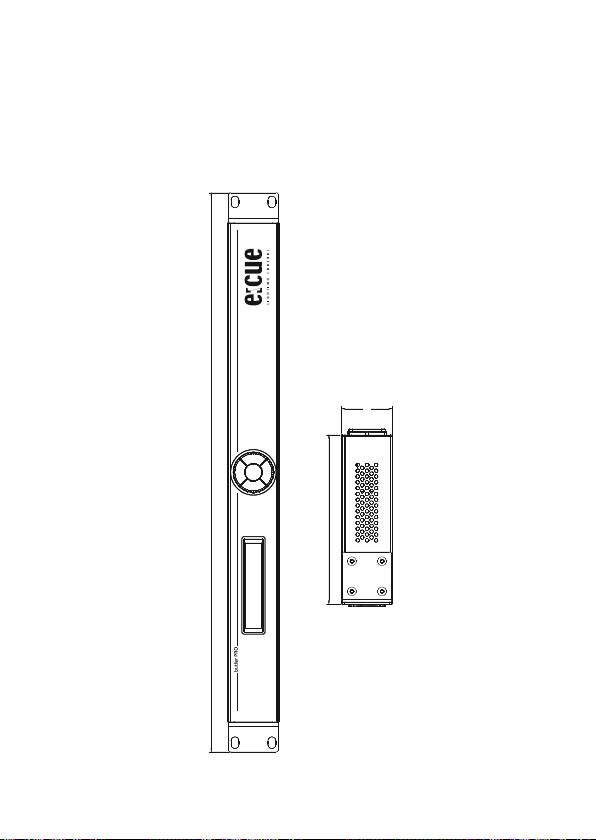
Dimensions/Abmessungen
All dimensions in mm/Alle Abmessungen in mm
482
Setup Manual - Butler PRO
44
146
47
Page 48

Setup Manual - Butler PRO
Notes/Notizen
48
Page 49

Notes/Notizen
Setup Manual - Butler PRO
49
Page 50

Setup Manual - Butler PRO
Notes/Notizen
50
Page 51

Notes/Notizen
Setup Manual - Butler PRO
51
Page 52

Downloads and more information at
www.traxontechnologies.com and www.ecue.com
HONG KONG SHANGHAI TOKYO SINGAPORE ROTTERDAM COLOGNE LONDON
MADRID MILAN PARIS ISTANBUL DENMARK MOSCOW WARSZAWA VIENNA
NEW YORK TORONTO DUBAI BUENOS AIRES MEXICO D.F. SAO PAULO COLOMBIA
MUMBAI
FLEXIBILITY, SIMPLICITY & INNOVATION IN LIGHTING SOLUTIONS & SERVICES
 Loading...