

Page 1
Operation Manual
For Model 135 Warming Units
Cincinnati Sub-Zero Products, LLC 12011 Mosteller Road Cincinnati, Ohio 45241, U.S.A.
WarmAir®, FilteredFlo and Warming Tube
Copyright 2018, Cincinnati Sub-Zero Products, LLC, All rights reserved.
www.cszmedical.com
™
are Registered Trademarks of
Cincinnati Sub-Zero Products, LLC
Part No. 57128
57128 Rev. Q
ECN M1801-5437
Page 2

WarmAir
Model 135 Manual
How to get Technical Help
How to Contact Manufacturer (for Customer Service, Order Placement, or Technical Support):
Cincinnati Sub-Zero Products, LLC Telephone 1-800-989-7373
12011 Mosteller Road (U.S) 24hr Clinical Support 1-513-460-2038
Cincinnati, OH 45241 Med Tech Support 1-888-437-5608
United States of America Fax 1-513-772-9119
Website www.cszmedical.com
Email csz@genthermcsz.com
Before You Call for Service...
To help us better serve you, please have the serial number of your WarmAir135 unit ready when you call for parts or
service. The serial number is located on the back plate of the WarmAir135 unit.
In-Warranty Repair and Parts
WarmAir 135 units are covered by a one-year warranty. To return defective parts or units, obtain a Returned Materials
Authorization (RMA) number from our Medical Technical Service department. A WarmAir
will be sent to you, if needed. Extended Warranty Available.
Receiving Inspection
After unpacking the WarmAir135 unit, inspect the system for concealed damage. Retain all packing material and
carefully record or photograph any damage. Notify the carrier at once and ask for an inspection (in writing). Failure to do
this within 15 days may result in loss of claim. Do not return the equipment to Cincinnati Sub-Zero. Call our Medical
Technical Service department for further instructions.
Important Safety Information
Refer to this manual for instructions and caregiver information. Read and understand all precautionary
information before using, prescribing, or servicing the WarmAir135 unit. See the Operation and Technical
Manual for details on how to perform maintenance.
Model 135 shipping carton
Cincinnati Sub-Zero Products, LLC Page 2 of 17
Page 3

WarmAir
Model 135 Manual
Table of Contents
How to get Technical Help ............................................................................................................. 2
How to Contact Manufacturer (for Customer Service, Order Placement, or Technical Support): ......... 2
Before You Call for Service... ............................................................................................................. 2
In-Warranty Repair and Parts .......................................................................................................... 2
Important Safety Information ....................................................................................................... 2
Table of Contents ........................................................................................................................... 3
Symbols ........................................................................................................................................... 4
Section 1: Safety Precautions ....................................................................................................... 5
General Description of the WarmAir
®
135 ........................................................................................ 5
Indications for Use ........................................................................................................................... 5
Contraindications ............................................................................................................................ 5
Warnings ......................................................................................................................................... 6
Precautions ..................................................................................................................................... 7
Read Before Servicing Equipment .................................................................................................... 7
Section 2: Specifications ............................................................................................................... 8
Physical ........................................................................................................................................... 8
Electrical ......................................................................................................................................... 8
Temperature Control System ........................................................................................................... 8
Safety System .................................................................................................................................. 9
Service Life ...................................................................................................................................... 9
Approvals ........................................................................................................................................ 9
For Use with Patient-Applied Parts ................................................................................................ 12
Shipping and Storage Conditions .................................................................................................... 12
Section 3: Operating Instructions ............................................................................................... 13
Control Panel and Operation Label ................................................................................................. 13
Operation Fundamentals................................................................................................................ 13
Selecting Temperature and Using the Control Panel ........................................................................ 14
Mounting the WarmAir
Unit ......................................................................................................... 16
Section 4: Preventive Maintenance ............................................................................................ 17
Cleaning the Unit ........................................................................................................................... 17
Hour Meter ................................ ................................................................ ................................ .... 17
Worldwide Order Placement ...................................................................................................... 17
Illustrations
Control Panel and Operation Label ................................................................................................................................. 13
Cincinnati Sub-Zero Products, LLC Page 3 of 17
Page 4
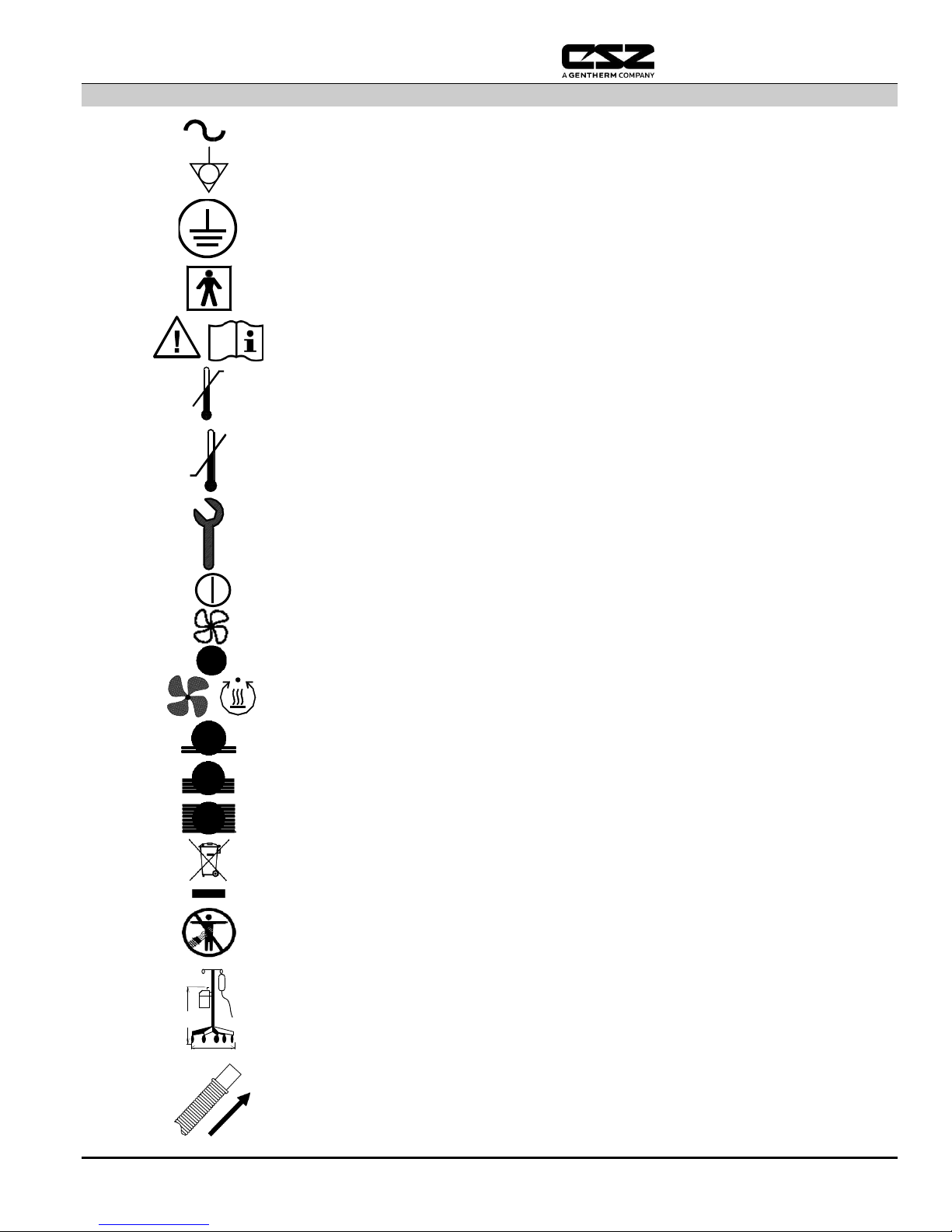
Symbols
Voltage, Alternating Current
Potential Equalization Connection (Grounding)
Protective Earth (Ground)
Type BF Equipment (per IEC-601-1)
(Patient Applied)
Consult instructions for use and/or manual before operating
Over-Temperature Safety Limit
Under-Temperature Safety Limit
Hour Meter
Power On/Off Indicator
Fan Only Selection
Temperature Selection Switches
Low setting: 32.2°C
Medium setting: 37.8°C
High setting: 43.3°C
Separate collection for electrical and Electronic equipment. Dispose of the
WarmAir unit per hospital protocol.
CAUTION! Hose Nozzle MUST be connected to a compatible Forced Air
Blanket or thermal injury may occur.
WARNING: To prevent tipping when mounting the Model 135 unit to an IV
pole, clamp the unit no higher than 44 inches (112 cm) on an IV pole with a
minimum 24 inch (61 cm) diameter base. Failure to heed these restrictions
may result in IV pole instability, catheter site trauma, and patient/user
injury. Note: For instructions on use of the symbols, refer to the “Operating
Instructions” section
Insert Hose
<44”
<112cm
>24” >61cm
WarmAir
Model 135 Manual
Cincinnati Sub-Zero Products, LLC Page 4 of 17
Page 5

Safety Precautions WarmAir Model 135 Manual
Section 1: Safety Precautions
Cincinnati Sub-Zero Products, LLC, reserves the right to make changes to the device, which may not be reflected in this
manual.
General Description of the WarmAir® 135
The WarmAir® 135 unit is a small and compact warming unit designed to supply air at temperatures of ambient, 32.2°C,
37.8°C or 43.3°C to a patient-applied air-distribution device. The settings are termed “Fan Only”, “Low”, “Medium” and
“High”, respectively.
Indications for Use
The WarmAir® 135 patient warming system is intended to prevent hypothermia and/or reduce cold discomfort before,
during, and after surgical procedures. The thermal regulating system is used to raise a patient’s temperature and/or
maintain a desired patient temperature through convective heat transfer from the controller to a warm-air-heated
blanket. The single-patient use blankets transfer the thermal energy to adult, pediatric or neonate patients to
obtain/maintain normal body temperature. It is intended for use by appropriately trained healthcare professionals in
clinical environments.
Contraindications
High temperature settings to be used with close patient observation when treating patients with the following conditions:
Significant peripheral vascular disease, occlusive or diabetic in nature.
Low cardiac output.
Marginal cutaneous perfusion.
Do not apply heat to lower extremities during arterial cross-clamping. Thermal injury may occur if heat is applied to
ischemic limbs.
Cincinnati Sub-Zero Products, LLC Page 5 of 17
Page 6

Safety Precautions WarmAir Model 135 Manual
Warnings
A Licensed Healthcare Practitioner's order is required for setting temperature and use of equipment.
At least every 20 minutes, or as directed by a Licensed Healthcare Practitioner, check the patient's
temperature and skin condition of areas in contact with the disposable blanket. Pediatric and
temperature-sensitive patients should be checked more frequently. Notify the Licensed Healthcare
Practitioner promptly of any change in order to avoid serious injury.
Patient temperature depends on ambient temperature and additional sheets or blankets. Reduce or
discontinue therapy when therapeutic goal is reached or if vital signs instability occurs. Thermal
injury may result. Notify Licensed Healthcare Practitioner immediately of vital signs instability.
Do not use the WarmAir
135 unit distal to arterial cross clamping. Thermal injury may result.
Do not use the WarmAir
135 unit along with High Frequency surgical instruments or endocardial
catheters. Electrical shock, thermal injury or electromagnetic interference may result.
Notify the Licensed Healthcare Practitioner promptly if any of the following occur:
If the patient's temperature is not responding properly,
If the patient's temperature does not reach the prescribed temperature in the prescribed time, or
If there is a change in the prescribed temperature range. Failure to inform the Licensed Healthcare
Practitioner of the deviation may result in injury to the patient.
The warming of transdermal medications (patches) can increase drug delivery, resulting in possible
injury to the patient.
Do not use the WarmAir
Model 135 unit with any blanket or warming cover other than CSZ
FilteredFlo Blankets or the Warming Tube. Thermal injury may result.
Do not attempt to warm patient without a blanket, i.e. with the hose only. Thermal injury may result.
Unapproved modifications may cause patient/caregiver injury and/or equipment damage.
Do not continue therapy if either the Over-Temperature or Under-Temperature warning light activates
or the audible alarm sounds. Do not continue therapy if power cannot be maintained to the unit.
Thermal injury may result. Turn the unit off and remove from service.
Do not initiate therapy unless the WarmAir
135 unit is securely mounted or injury may result.
Always unplug the unit before accessing internal components during service. Failure to unplug the
unit could result in electric shock.
Do not by-pass ground lug. Electrical Hazards may result.
The use of materials of good thermal conductivity, such as water, gel and similar substances, with the
WarmAir135 unit not switched on, can decrease the body temperature of a patient.
Thermal injury may occur if heating therapy is applied to ischemic limbs.
Do not use the WarmAir
135 unit in the presence of flammable anesthetics. Risk of explosion may
result.
The WarmAir
135 unit disposables (FilteredFlo Blankets, Warming Tube) are not sterile and are
intended for single patient use only. DO NOT sterilize or reprocess these disposables. Thermal injury
and/or cross-contamination may result.
Do not allow the hose to contact the patient. Thermal injury may result.
Do not return the WarmAir
135 unit to service without the filter present. Thermal injury may
result.
Do not use the WarmAir
135 unit without the designated filter in place. Thermal injury or airborne
contamination may result.
Electrical shock hazard. To avoid risk of electrical shock, disconnect power before servicing.
To avoid the risk of electric shock, this equipment must only be connected to a supply mains with
protective earth.
Cincinnati Sub-Zero Products, LLC Page 6 of 17
Page 7

Safety Precautions WarmAir Model 135 Manual
Precautions
CAUTION: Federal law (U.S.A.) restricts this device to sale by or on the order of a Licensed Healthcare
Practitioner.
Read all instructions provided with CSZ FilteredFlo
Blankets or the Warming Tube prior to use.
The surface of the WarmAir
135 unit and CSZ FilteredFlo Blanket or Warming Tube should be
checked for freedom from mechanical damage prior to each application.
The WarmAir
135 unit is not intended for use in ambient temperatures above 30°C. Maximum contact
surface temperature, during normal operation, is 48°C.
Do not hipot or dielectric test the WarmAir
135 unit. Only apply the rated voltage to the unit.
Subjecting the unit to voltages other than the rated voltage may cause damage to the unit. These tests
are done only by CSZ.
Power interruption will cause the WarmAir
135 unit to shut down, resulting in no therapy to the
patient. Follow instructions listed under the “Operation Fundamentals” section of this manual to
resume therapy.
All temperature settings represent temperatures at the end of the hose outlet, not blanket surface
temperature.
Medical electrical equipment needs special precautions regarding EMC and needs to be installed and
put into service according to the EMC table information provided in this manual.
Portable and mobile RF communications equipment can affect medical electrical equipment
Other cables and accessories may affect EMC performance
Avoid stacking or locating close to other equipment according to the EMC tables.
If a means is needed in retaining a patient either on or under a CSZ FilteredFlo
Blanket or the Warming
Tube, the means should not block the fluid pathways of the WarmAir135 unit.
Read Before Servicing Equipment
The repair, calibration and servicing of the WarmAir135 unit must be performed by qualified Medical Equipment Service
Technicians, Certified Biomedical Electronics Technicians, or Certified Clinical Engineers familiar with good repair
practices for servicing medical devices in accordance with the instructions contained in the Operation and Technical
manual. Improper repair can result in patient or user injury and damage to the WarmAir135 unit. Do not hipot unit.
Improper repair may also void the warranty. Reference the Operation & Technical manual for Troubleshooting
instructions.
Cincinnati Sub-Zero Products, LLC Page 7 of 17
Page 8

Specifications WarmAir Model 135 Manual
Temperature Settings as
measured at the hose outlet of
the device:
No Heat (ambient temperature)
32.2°C +4.0°C/ -2.0°C
37.8°C +4.0°C/ -2.0°C
43.3°C +4.0°C/ -2.0°C
Section 2: Specifications
Physical
Dimensions: 22.2 cm x 22.2 cm x 34.3 cm
Hose Outlet: 1.8m flexible hose
Weight: 6.1 kg
Filtration: 0.2 microns, High Efficiency
Construction: Impact-resistant plastic case with aluminum sub-structure. None of the WarmAir System components
are made with natural rubber latex.
Electrical
WarmAir135 unit is available in 100V, 110-120V or 220-240V:
100V, 50/60 Hz and 110-120V, 50/60Hz units:
1200 VA
15 Amp Circuit Breaker
15' (4.6m) Power Cord (14/3 SJT with Hospital-Grade plug)
220-240V, 50/60Hz units:
1200 VA
7 Amp Circuit Breaker
15’ (4.6m) Harmonized Power Cord (H05VV-F 3x1.5mm² cord
with CEE 7/7 plug)
220-240V, 50/60Hz units:
1200VA
13 Amp Circuit Breaker
15’ (4.6m) British Standard Power Cord (HO5VVF3G1.5mm
Molded-on BS1363 fused male plug)
For all units:
Under 300 A earth leakage current
Ground resistance 0.2 or less
Mains Supply Isolation: Two-Pole Mains Switch
Temperature Control System
Control System: Microprocessor and thermistor-based.
Operating Environment:
Temperature: 15°C to 30°C (59°F to 86°F)
Relative Humidity: 20% - 60%
Maximum Contact Surface Temperature (during normal operation): 48°C
Time to reach 37°C from 23±2°C: Approximately 3 minutes
Cincinnati Sub-Zero Products, LLC Page 8 of 17
Page 9

Specifications WarmAir Model 135 Manual
Maximum Temperature Setting:
43.3°C +4.0°C
Independent Primary
Over-Temperature Limit:
52.0°C ± 3.0°C as measured at the hose outlet
of the device (i.e. where the hose connects to
the blanket).
Audible and visible alarms.
Heater and blower shutdown.
Note: Based on testing, the maximum
contact surface temperature of the
blanket, when the primary overtemperature limit activates is 45°C ±
3.0°C.
Independent Secondary Over-Temperature
Limit:
64°C or less as measured at the hose outlet of
the device (i.e. where the hose connects to the
blanket).
Power shutdown.
Note: Based on testing, the maximum
contact surface temperature of the
blanket, when the secondary overtemperature limit activates is 45°C ±
3.0°C.
Independent Under-Temperature Limit:
29.4°C or less as measured at the hose outlet
of the device (i.e. where the hose connects to
the blanket).
Audible and visible alarms.
Heater and blower shutdown.
(Heat settings only).
Open/Shorted Sensor Safety:
Audible and visible alarms.
MODEL 135, MEDICAL ELECTRICAL
EQUIPMENT IN ACCORDANCE WITH UL606011, IEC60601-1 AND ASTM F2196-02.
ALSO CLASSIFIED WITH RESPECT TO
ELECTRICAL SHOCK, FIRE AND MECHANICAL
HAZARDS ONLY IN ACCORDANCE WITH CSA
22.2 NO. 601.1
16HV
Safety System
Service Life
The expected service life / lifetime of the WarmAir135 unit is seven (7) years from the date of manufacture provided
the product is not subject to misuse, negligence, accident or abuse and under the conditions that the device is properly
used as intended, and serviced and maintained according to the Operation / Technical Manual provided with the device.
Approvals
Electrical
Cincinnati Sub-Zero Products, LLC Page 9 of 17
Page 10

Specifications WarmAir Model 135 Manual
Guidance and manufacturer’s declaration – electromagnetic emissions
The WarmAir, Model 135 is intended for use in the electromagnetic environment specified below. The customer or the user of this unit
should assure that it is used in such an environment.
Emissions tests
Compliance
Electromagnetic environment – guidance
RF emissions
CISPR 11
Group 1
The WarmAir, Model 135 uses RF energy only for its internal function.
Therefore, its RF emissions are very low and are not likely to cause
any interference in nearby electronic equipment.
RF emissions
CISPR 11
Class A
The WarmAir, Model 135 is suitable for use in all establishments
other than domestic and those directly connected to the public lowvoltage power supply network that supplies buildings used for
domestic purposes.
Fluctuations and Flicker emissions testing is not required or 120 or
100 Volt units
Harmonic emissions
IEC 61000-3-2
Class A
Voltage fluctuations/
flicker emissions
IEC 61000-3-3
Complies
Guidance and Manufacturer’s Declaration – electromagnetic immunity
The WarmAir, Model 135 is intended for use in the electromagnetic environment specified below. The customer or the user of the WarmAir,
Model 135 should assure that it is used in such an environment.
Immunity test
IEC 60601 test level
Compliance level
Electromagnetic environment - guidance
Electrostatic
discharge (ESD)
IEC 61000-4-2
±6 kV contact
±8 kV air
±6 kV contact
±8 kV air
Floors should be wood, concrete or ceramic tile. If floors
are covered with synthetic material, the relative humidity
should be at least 30%.
Electrical fast
transient/burst
IEC 61000-4-4
±2 kV for power supply
lines
±1 kV for input/output
lines
±2 kV for power supply
lines
±1 kV for input/output
lines
Mains power quality should be that of a typical commercial
or hospital environment.
Surge
IEC 61000-4-5
±1 kV differential mode
±2 kV common mode
±1 kV differential mode
±2 kV common mode
Mains power quality should be that of a typical commercial
or hospital environment.
Voltage dips, short
interruptions and
voltage variations on
power supply input
lines
IEC 61000-4-11
<5% UT
(>95% dip in UT)
for 0,5 cycle
40% UT
(60% dip in UT)
for 5 cycles
70% UT
(30% dip in UT)
for 25 cycles
<5% UT
(>95% dip in UT)
for 5 s
<5% UT
(>95% dip in UT)
for 0.5 cycle
40% UT
(60% dip in UT)
for 5 cycles
70% UT
(30% dip in UT)
for 25 cycles
<5% UT
(>95% dip in UT)
for 5 s
Mains power quality should be that of a typical commercial
or hospital environment. If the user of the WarmAir, Model
135 requires continued operation during power mains
interruptions, it is recommended that the WarmAir, Model
135 be powered from an uninterruptible power supply or
a battery.
Power frequency
(50/60 Hz) magnetic
field
IEC 61000-4-8
3 A/m
3 A/m
Power frequency magnetic fields should be at levels
characteristic of a typical location in a typical commercial
or hospital environment.
Note: UT is the a. c. mains voltage prior to application of the test level.
EMC COMPATIBILITY TABLES ACCORDING TO IEC 60601-1-2
Cincinnati Sub-Zero Products, LLC Page 10 of 17
Page 11

Specifications WarmAir Model 135 Manual
Guidance and manufacturer’s declaration – electromagnetic immunity
The WarmAir, Model 135 is intended for use in the electromagnetic environment specified below. The customer or the user of the WarmAir,
Model 135 should assure that it is used in such an environment.
Immunity test
IEC 60601 test level
Compliance level
Electromagnetic environment - guidance
Conducted RF
IEC 61000-4-6
Radiated RF
IEC 61000-4-3
3 Vrms
150 kHz to 80 MHz
3 V/m
80 MHz to 2,5 GHz
3 Vrms
3 V/m
Portable and mobile RF communications equipment
should be used no closer to any part of the WarmAir,
Model 135, including cables, than the recommended
separation distance calculated from the equation
applicable to the frequency of the transmitter.
Recommended separation distance
d = 1,2√P
d = 1,2√P 80 MHz to 800 MHz
d = 2,3√P 800 MHz to 2,5 GHz
where P is the maximum output power rating of the
transmitter in watts (W) according to the transmitter
manufacturer and d is the recommended separation
distance in meters (m).
Field strengths from fixed RF transmitters, as determined
by an electromagnetic site survey,
a
should be less than the
compliance level in each frequency range. b
Interference may occur in the vicinity of equipment
marked with the following symbol:
NOTE 1: At 80 MHz and 800 MHz, the higher frequency range applies.
NOTE 2: These guidelines may not apply in all situations. Electromagnetic propagation is affected by absorption and reflection from
structures, objects and people.
a
Field strengths from fixed transmitters, such as base stations for radio (cellular/cordless) telephones and land mobile radios, amateur
radio, AM and FM radio broadcast and TV broadcast cannot be predicated theoretically with accuracy. To assess the electromagnetic
environment due to fixed RF transmitters, an electromagnetic site survey should be considered. If the measure field strength in the
location in which the WarmAir, Model 135 is used exceeds the applicable RF compliance level above, the WarmAir, Model 135 should
be observed to verify normal operation. If abnormal performance is observed, additional measures may be necessary, such as reorienting or relocating the WarmAir, Model 135.
b
Over the frequency range 150 kHz to 80 MHz, field strengths should be less than 3 V/m.
Cincinnati Sub-Zero Products, LLC Page 11 of 17
Page 12

Specifications WarmAir Model 135 Manual
Recommended separation distances between portable and mobile RF communications
equipment and the WarmAir, Model 135
The WarmAir, Model 135 is intended for use in an electromagnetic environment in which radiated RF disturbances are
controlled. The customer or the user of the WarmAir, Model 135 can help prevent electromagnetic interference by maintaining a
minimum distance between portable and mobile RF communications equipment (transmitters) and the WarmAir, Model 135 as
recommended below, according to the maximum output power of the communications equipment.
Rated maximum
output power of
transmitter
W
Separation distance according to frequency of transmitter
m
150 kHz to 80 MHz
d = 1,2√P
80 MHz to 800 MHz
d = 1,2√P
800 MHz to 2,5 GHz
d = 2,3√P
0,01
0,12
0,12
0,23
0,1
0,38
0,38
0,73 1 1,2
1,2
2,3
10
3,8
3,8
7,3
100
12
12
23
For transmitters rated at a maximum output power not listed above, the recommended separation distance d in meters (m) can
be estimated using the equation applicable to the frequency of the transmitter, where P is the maximum output power rating of
the transmitter in watts (W) according to the transmitter manufacturer.
Note 1: At 80 MHz and 800 MHz, the separation distance for the higher frequency range applies.
Note 2: These guidelines may not apply in all situations. Electromagnetic propagation is affected by absorption and reflection
from structures, objects and people.
WarmAir accessories and additional technical information is available in the Operation &
Technical Manual
Supplemental certification or EMC information available on request.
For Use with Patient-Applied Parts
FilteredFlo Blankets and Warming Tube
All CSZ disposables are:
Note: Do not sterilize or reprocess CSZ disposables.
Shipping and Storage Conditions
The WarmAir135 unit can be transported through normal shipping methods via ground, air, or water when packaged in its
original packaging material. During transportation and storage, packaging should not be exposed to conditions that
fall out of the ranges below:
1. Made from non-woven polypropylene or polyethylene.
2. Manufactured to meet the flammability standards of the Flammable Fabrics Acts and NFPA 99 for Health Care
Facilities.
3. Transparent to X-ray and imaging systems.
4. For single-patient use only.
5. Not sterile unless otherwise indicated on product.
1.1.1 Temperature: -40C to 50C (–40F to 122F)
1.1.2 Humidity: 5% to 95%
Cincinnati Sub-Zero Products, LLC Page 12 of 17
Page 13

Operating Instructions WarmAir Model 135 Manual
Insert hose. Insert the free end of the flexible hose into the air inlet port of the
FilteredFlo Blanket or Warming Tube. Make sure the hose is pushed in
beyond the raised areas on the fitting.
Power Unit On. Using the rocker switch on the side of the unit, depress the “I”
side to activate power to the unit. Depressing the “O” side deactivates power.
been selected.
Select Temperature. Activate the desired temperature setting using the four
touch-sensitive buttons, applying the following instructions.
Section 3: Operating Instructions
Control Panel and Operation Label
The control panel and operation label for the WarmAir
135 unit are located on the top of the unit.
Operation Fundamentals
The lower portion of the control panel gives a brief description of operating the WarmAir System. Read all instructions
and safety precautions included with the FilteredFlo Blanket or Warming Tube.
For all WarmAir Systems
Cincinnati Sub-Zero Products, LLC Page 13 of 17
Page 14

Power On/Off Indicator. This LED light will indicate that the unit is on. A
temperature selection can now be made. Power is toggled at the rocker switch on
the side of the unit.
Temperature Selection Switches. Four temperature selection switches on the
control panel allow the caregiver to select a temperature setting for the patient.
Fan Only Depressing this switch will activate the unit to draw in ambient room
temperature air and deliver it to the patient via the disposable blanket. The heater
will not be activated. The temperature delivered to the patient will depend on the
current room temperature during operation of the unit. (Air temperature delivered
may be up to three degrees higher than the ambient temperature due to heat from
the blower motor.) The LED will be activated to indicate that the unit is in the
ambient temperature mode.
Low Temperature. Depressing this switch will activate the unit to draw in room
air, heat the air to 32.2°C +4.0°C/ -2.0°C and deliver it to the patient via the
disposable blanket. The LED will be activated to indicate that the unit is in the low
temperature mode.
Medium Temperature. Depressing this switch will activate the unit to draw in
room air, heat the air to 37.8°C +4.0°C/ -2.0°C and deliver it to the patient via the
disposable blanket. The LED will be activated to indicate that the unit is in the
medium temperature mode.
High Temperature. Depressing this switch will activate the unit to draw in room
air, heat the air to 43.3°C +4.0°C/-2.0°C and deliver it to the patient via the
disposable blanket. The LED will be activated to indicate that the unit is in the high
temperature mode. The high temperature setting is to be used with close
patient observation.
Selecting Temperature and Using the Control Panel
The control panel is located on top of the unit and is composed of four pressure sensitive touch switches, each having a
LED display. The external features on the control panel of the WarmAir unit are described as follows:
Cincinnati Sub-Zero Products, LLC Page 14 of 17
Page 15

CAUTION!
High temperature setting to be used with close patient observation when treating patients
with the following conditions:
a. Significant peripheral vascular disease, occlusive or diabetic in nature.
b. Low cardiac output.
c. Do not apply to ischemic limbs, e.g., during arterial cross-clamping.
CAUTION!
Do not attempt to warm patient with hose only. Operating the WarmAir135 unit without a
blanket may result in patient injury.
CAUTION!
High temperature setting to be used with close patient observation. Reduce air temperature
or discontinue therapy when the therapeutic goal is reached or if vital signs instability
occurs.
Over-Temperature Safety Limit. This LED indicator light will indicate an overtemperature condition (an audible alarm will also sound). Immediately
discontinue use and remove from service if activated.
Under Temperature Safety Limit. This LED indicator light will indicate an undertemperature condition (an audible alarm will also sound). Immeidately
discontinue use and remove from service if activated.
Hour Meter. This LED indicator will alert the caregiver that 500 hours of
service has transpired and the unit is due for its regular preventative
maintenance, including changing the filter.
!
!!!
Cincinnati Sub-Zero Products, LLC Page 15 of 17
Page 16

WARNING!
To prevent tipping when mounting the Model 135 unit to an IV
pole, do not clamp the unit higher than 112 cm on an IV pole with a
minimum 61 cm diameter base. When hooking the unit on a rail,
make sure the unit cannot tip to a point where it may fall off the
rail.
When placing the unit on a table or stand near a patient, make sure
the unit is not located in an area where it can be knocked off by
caregivers or passing traffic.
Failure to heed these restrictions may result in IV pole instability,
catheter site trauma, and patient or user injury.
!
Mounting the WarmAir Unit
The WarmAir135 unit must be mounted securely before it is used. There are three ways to mount the unit:
1. IV Pole Clamp The unit may hook onto a secure, vertical IV pole of no less than 2.2 cm and no more than
2.86 cm in diameter.
2. Mounting The unit may hook onto a secure bed rail or footboard up to 3.8 cm
Bracket thick.
3. Anti-slip Feet The unit may be placed on a table or stand near the patient. Do not place the unit in bed with
the patient.
Cincinnati Sub-Zero Products, LLC Page 16 of 17
Page 17

Preventive Maintenance WarmAir Model 135 Manual
CAUTION!
Disconnect from power when cleaning the Warming Unit. Allow
to air dry thoroughly. Do not use dripping wet cloth or otherwise
allow water to seep into electrical areas of the WarmAir135
unit.
!
Section 4: Preventive Maintenance
Cleaning the Unit
For cleaning and disinfecting always use conventional hospital-approved, topical equipment cleaners, and disinfectants.
Thoroughly wipe down device with a damp cloth to remove any residue from cleaning solutions. Ensure that all
inaccessible cracks and crevices on the WarmAir are reached during cleaning.
Hour Meter
The WarmAir135 unit is equipped with a built-in timer that will activate the "Hour Meter" light after 500 hours of use.
This is an indication that routine maintenance is required. See Operation & Technical Manual for instructions. Instructions
on replacing the WarmAir135 air filter are also located in the Operation & Technical Manual.
WarmAir135 unit has approval in accordance with IEC 80601-2-35. These standards are based on contact surface
temperature of the blanket being 48°C or less. Temperatures referenced at the hose outlet do not represent
contact surface temperatures of the blanket due to temperature loss through the hose and dispersion through the
blanket.
Worldwide Order Placement
United States and Canada Telephone 1-800-989-7373
(U.S.) 24hr Clinical Support 1-513-460-3028
Healthlink Europe Fax 1-513-772-9119
De Tweeling 20-22 Med Tech Support 1-888-437-5608
5215 MC’s Hertogenbosch
The Netherlands
Cincinnati Sub-Zero Products, LLC Page 17 of 17
Page 18

Telephone: 1-800-989-7373 Fax: (513)772-9119
Cincinnati Sub-Zero Products, LLC
12011 Mosteller Road
Cincinnati, OH 45241
 Loading...