

Page 1

P6LX-A Mainboard
User’s Manual
Page 2

P6LX-A User’s Manual
Table Of Contents – 2
FCC & DOC ComplianceFCC & DOC Compliance
FCC & DOC Compliance
FCC & DOC ComplianceFCC & DOC Compliance
Federal Communications Commission StatementFederal Communications Commission Statement
Federal Communications Commission Statement
Federal Communications Commission StatementFederal Communications Commission Statement
This device complies with FCC Rules Part 15. Operation is subject to the following two
conditions:
• This device may not cause harmful interference, and
• This device must accept any interference received, including interference that may cause
undesired operation.
This equipment has been tested and found to comply with the limits for a Class B digital
device, pursuant to Part 15 of the FCC Rules. These limits are designed to provide reasonable
protection against harmful interference in a residential installation. This equipment generates, uses and can radiate radio frequency energy and, if not installed and used in accordance
with the manufacturer’s instructions, may cause harmful interference to radio communications. However, there is no guarantee that interference will not occur in a particular installation. If this equipment does cause harmful interference to radio or television reception, which
can be determined by turning the equipment off and on, the user is encouraged to try to
correct the interference by one or more of the following measures:
• Re-orient or relocate the receiving antenna.
• Increase the separation between the equipment and the receiver.
• Connect the equipment to an outlet on a circuit different from that to which the receiver
is connected.
• Consult the dealer or an experienced radio/TV technician for help.
WW
arar
ning!ning!
W
ar
ning! The use of shielded cables for the connection of the monitor to the graphics
WW
arar
card is required to assure compliance with FCC regulations. Changes or modifications to this
unit not expressly approved by the party responsible for compliance could void the user’s
authority to operate this equipment.
ning!ning!
Canadian DeparCanadian Depar
Canadian Depar
Canadian DeparCanadian Depar
This digital apparatus does not exceed the Class B limits for radio noise emissions from
digital apparatus set out in the Radio Interference Regulations of the Canadian Department
of Communications.
Version 1.1a
Copyright © September 1997 All rights reserved
This publication may not be copied, reproduced, translated, transmitted or reduced to
any printed or electronic medium or to any machine readable form, or stored in a retrieval
system, either in whole or in part without the written consent of the copyright holders.
The contents of this publication are subject to change. The manufacturer reserves the
right to alter the contents of this publication at any time and without notice. The contents of
this publication may contain inaccuracies or typographical errors and is supplied for informational use only.
Products are noted in this publication for identification purposes only. Microsoft is a
registered trademark and Windows is a trademark of Microsoft Corporation. Pentium is a
trademark of Intel Corporation. All other product names or brands may be trademarks or
registered trademarks of their respective holders.
tment of Communications Statementtment of Communications Statement
tment of Communications Statement
tment of Communications Statementtment of Communications Statement
Page 3

P6LX-A User’s Manual
Table Of Contents – 3
1: P6LX-A Package & Product Information ............ 1.1
Manual Features.......................................................................... 1.1
Package Contents............................................................... 1.3
Mainboard Features ........................................................... 1.4
Component Information ..................................................... 1.6
Expansion Slots ............................................................................ 1.6
Memory Sockets & Modules ....................................................... 1.7
CPU Socket & CPU ....................................................................... 1.8
Port & Controller Connections ..................................................... 1.8
2: Using Your Mainboard ....................................... 2.1
System Controls.................................................................. 2.1
Hardware Controls & Indicators ................................................. 2.1
CMOS Setup Utility Controls......................................................... 2.3
Hardware Features............................................................. 2.6
Onboard Ports.............................................................................. 2.6
Connectors ...................................................................................2.6
Optional Hardware Connectors.................................................. 2.10
The CPU Retention Module................................................. 2.12
Firmware & Software.......................................................... 2.14
How To Use The CMOS Setup Utility ............................................ 2.14
Clearing CMOS............................................................................. 2.14
Flashing The BIOS......................................................................... 2.16
Bus Master Drivers.......................................................................2.16
SCSI Support Software ................................................................. 2.16
3: Reconfiguring Your Mainboard.......................... 3.1
Installing Expansion Cards .................................................. 3.1
ISA Cards & Slots.......................................................................... 3.1
Configuring Expansion Card Resources In CMOS Setup............ 3.2
Adding System Memory ..................................................... 3.5
Memory Configurations............................................................... 3.5
Page 4

P6LX-A User’s Manual
Table Of Contents – 4
Installing A CPU Upgrade ................................................... 3.8
The Basic Procedure ....................................................................3.8
Configuring Internal Clock Speed & Factor.................................3.8
CPU Jumper Table & Illustrations ................................................ 3.9
Adding An IDE Peripheral.................................................... 3.12
IDE Transfer Modes ...................................................................... 3.12
Installing IDE Devices.................................................................... 3.14
Adding SCSI Devices ........................................................... 3.15
SCSI Device IDs ............................................................................. 3.16
SCSI Termination........................................................................... 3.16
Installing an AGP Card........................................................ 3.16
4: P6LX-A Reference Information.......................... 4.1
Using This Section............................................................... 4.1
Jumper Configuration & Connector Summary .................... 4.3
The AGP Slot....................................................................... 4.8
The RAIDport™ Slot ............................................................ 4.8
Supported CPUs.................................................................. 4.8
System Memory Specifications........................................... 4.9
Memory Configurations............................................................... 4.9
CMOS Setup Utility Summary ............................................. 4.10
Using the CMOS Setup Utility.......................................................4.10
Accessing The CMOS Setup Utility............................................... 4.10
Standard CMOS Setup ................................................................. 4.14
BIOS Features Setup..................................................................... 4.18
Chipset Features Setup................................................................ 4.23
Power Management Setup .........................................................4.25
PNP/PCI Configuration................................................................. 4.31
Load BIOS Defaults....................................................................... 4.34
Load Optimum Settings ...............................................................4.34
Integrated Peripherals ................................................................. 4.35
PC Health Monitor........................................................................ 4.40
Page 5

P6LX-A User’s Manual
1: Package & Product Information – 1.1
In This Section:
About This Manual
Package Contents
Mainboard Features
Component Information
1: P6LX-A Package & Product Information
This manual contains all the information you’ll need to use
the P6LX-A mainboard. Please take a moment to familiarize yourself with the design and organization of the manual.
Manual Features
This manual is divided into four sections:
• Section 1: Package & Product Information
A brief overview of what comes in the mainboard package, its
basic features, layout and component information.
• Section 2: Using Your Mainboard
Information on mainboard features that you may make use of
in operating your computer.
• Section 3: Reconfiguring Your Mainboard
How to change or upgrade the mainboard configuration.
• Section 4: Reference Information
A summary of the mainboard’s settings and specifications.
Page 6

P6LX-A User’s Manual
1: Package & Product Information – 1.2
The manual uses some icons to call your attention to impor-
tant information. The icons appear in the sidebar and represent
the following:
G
C
D
N
• Important information
• A recommendation or good idea
• A warning or bad idea
• Danger warning
Online Manual Format
If the support disk for your mainboard is a CD-ROM disc, a
copy of the printed manual may be stored on the disc in Adobe
Acrobat format. If so, it requires Adobe Acrobat Reader version
3.0 or later to view it. Acrobat Reader for Microsoft Windows95
may also be supplied on the Support Disk. If not, you can obtain
a free copy of the Reader software from the Abobe web site which
is currently at www.adobe.com as well as other locations.
If you have the online manual, you may want to install Acro-
bat Reader on your system hard disk. You can copy the manual
over as well so that the manual is readily available without having to hunt up the Support Disk when you want to view it.
If you are unfamiliar with Acrobat Reader, please take a mo-
ment to view the Reader Online Guide which is available under
the Help menu when you run Reader.
Page 7

P6LX-A User’s Manual
1: Package & Product Information – 1.3
Package Contents
The P6LX-A mainboard package contains the following items.
Please inspect the package contents and confirm that everything
is there. If anything is missing or damaged, call your vendor for
instructions before proceeding. The package includes:
• P6LX-A Mainboard
• Cable Pack:
– 1 Floppy cable
– 1 IDE cable
– 1 50-pin Wide SCSI cable (with SCSI option)
• Support Disk:
– IDE Bus Master Drivers
– Adaptec SCSI support software (with SCSI option)
– Creative Labs Audio Drivers (with audio option)
– Infrared Module support software
The mainboard comes with IDE Bus Master drivers for several Operating Systems. The drivers are organized in individual
folders by OS. In each folder there is a “readme” file that explains
how to install the driver. Please locate the folder for the driver
you need and check this file.
Page 8

P6LX-A User’s Manual
1: Package & Product Information – 1.4
Mainboard Features
This mainboard is a highly integrated ATX design that incor-
porates many features on the board. The mainboard includes the
following features:
• Slot 1 CPU slot supports Pentium II CPUs up to 333MHz
• Intel 82440LX (PAC) and 82371AB (PIIX4) chipsets
• Super I/O chip
• NS LM78 Microprocessor System Hardware Monitor
– Supports LANDesk Client Manager PC Health Monitor
• Memory module sockets:
– 4 DIMM sockets support up to 512MB
• Onboard Audio (optional)
– Creative Labs Vibra16X audio chip
– External mini-jack Mic, Line-In and Line-Out connectors
– Creative audio driver and additional audio software
• Onboard SCSI (optional)
– Adaptec AIC-7880 SCSI controller
– Adaptec RAIDport™ slot for ARO-1130 RAID controller card
– 50-pin Wide SCSI connector
– 68-pin Ultra Wide SCSI connector
– SCSI support software for several Operating Systems
• External Ports
– COM1 & COM2 serial ports, Parallel port
– PS/2 Mouse & Keyboard connectors, dual USB ports
– Game/Joystick port, Mic, Line-In and Line-Out connectors
• Expansion Card Slots
– Four PCI 2.1–compliant PCI slots
– Three 16-bit ISA slots (ISA1 shares with PCI4)
– One AGP (Accelerated Graphics Port) slot
– RAIDport™ slot extension (extends PCI4)
Page 9

P6LX-A User’s Manual
1: Package & Product Information – 1.5
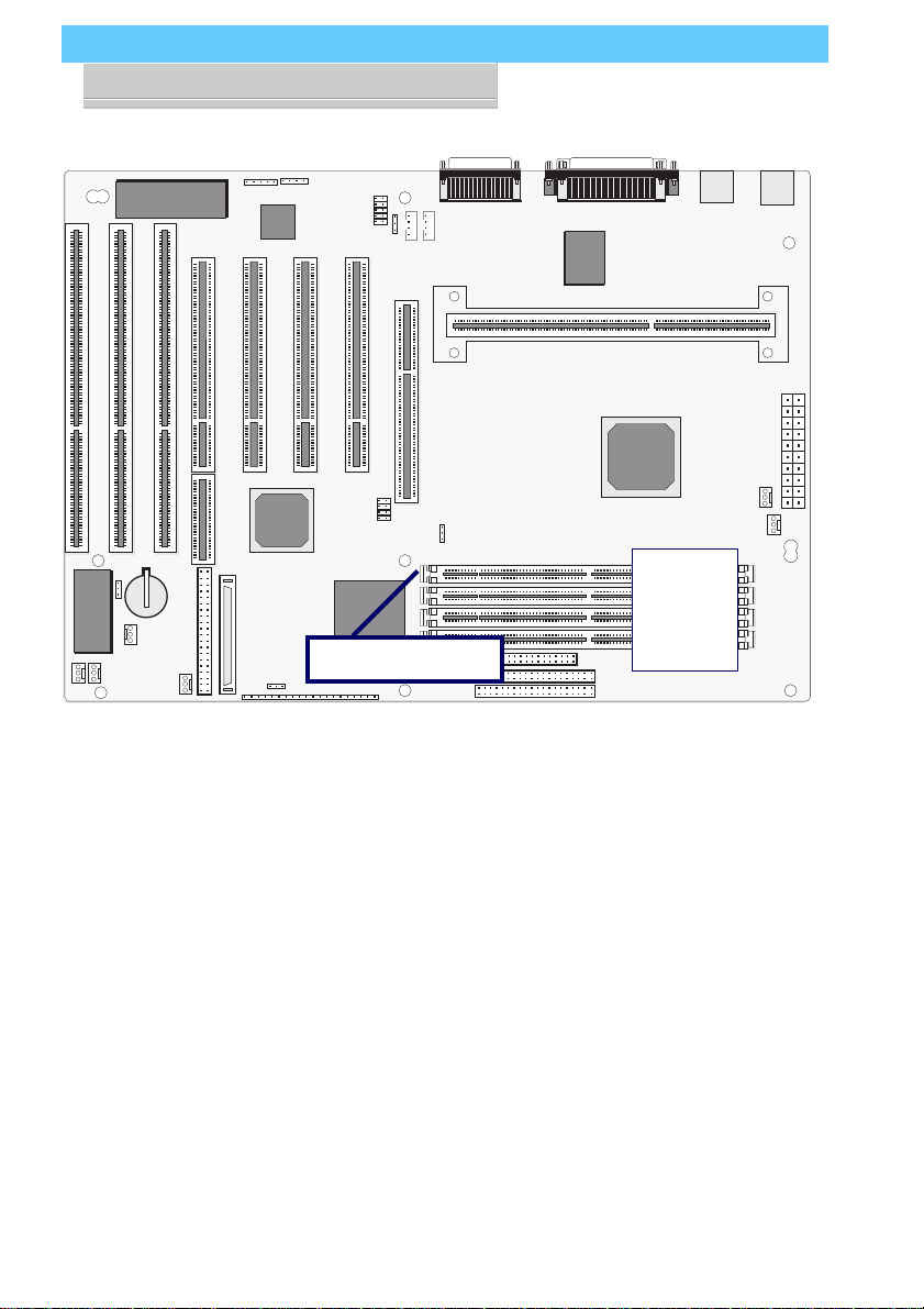
IR headers J11, J12
ISA 3, 2, 1
RAID
JP3
SCSI J22, J23
J40
J16
J15
J21
PCI 4,3,2,1
port
Game
Mic, Line-In, Line-Out
J25
CD-In J29, J26, J28
AGP Slot
JP5
JP1
Floppy
JP6
J9
Parallel
COM1
CPU Slot
DIMM1
DIMM2
DIMM3
DIMM4
Mouse
COM2
Keybd
USB
ATX Power
J13
J14
Secondary IDE
Primary IDE
P6LX-A Layout
The illustration above shows
the connectors, sockets and
ports and the mainboard.
The COM1 and COM2 ports
are underneath the Parallel
port.
The USB ports and the PS/2
ports – Keyboard (lower) and
Mouse (upper) – are stacked
one above the other.
The onboard audio connectors are under the game port.
Please see pages 4.6 and 4.7
for a full list of the onboard
connectors.
Page 10

P6LX-A User’s Manual
1: Package & Product Information – 1.6
Component Information
This section is a brief description of the components on the
mainboard that you might need to know about if you want to
upgrade or change your system configuration. If your mainboard
is already installed in a system, it isn’t necessary for you to review this section.
This mainboard uses the A TX ‘form factor’, a design that inte-
grates many features onto the board including some number of
external ports.
Expansion Slots
The mainboard has seven expansion slots for system expan-
sion or ‘add-on’ cards. Three are ISA slots, the others are PCI
slots. When you get an expansion card, it must use one of these
to connect to the computer.
The ISA expansion slots are a legacy of the original IBM PC/
A T design. They are 16-bit slots that run at a moderate bus speed.
There are many kinds of expansion cards that use this slot design
to connect to the computer, some of the most common being
sound and modem cards.
PCI slots are the current high-speed 32-bit standard for sys-
tem expansion cards. They operate at a faster speed and have a
greater data throughput than ISA cards.
Expansion cards often make use of system resources, which
requires managing the system resource configuration. Most newer
expansion cards support the ‘Plug and Play’ standard that allows
an Operating System like Windows95 to automatically detect
them and configure system resources as needed. Some older ISA
designs may not support this standard and may therefore require
manual configuration. You should consult the specifications or
documentation for a card to determine if this is the case and what
needs do be done to properly configure the card.
Page 11

P6LX-A User’s Manual
1: Package & Product Information – 1.7
The RAID
The slot extension to PCI4 is for the Adaptec RAIDport™ technology that allows you to add an Adaptec ARO-1130 or compatible RAID (Redundant Array of Independent Disks) controller
card. The card uses both the PCI slot and the extension.
With a RAID controller card installed, either or both SCSI types
on the mainboard can be used to establish a RAID array. Please
see Section 2 for information on using this feature.
port
™ Slot Extension
The AGP Slot
The AGP (Accelerated Graphics Port) slot is for an AGP 3D
video display card. Unlike PCI-based display cards, the AGP technology provides sufficient data throughput and speed to facilitate fully enabled 3-Dimensional and multimedia graphics display. AGP display cards using this dedicated slot are available
from a variety of vendors.
The AGP slot also requires Operating System support. Windows 98 directly supports AGP and other support methods may
be forthcoming. Please see Section 2 for more information.
Onboard SCSI Connections
This mainboard uses an Adaptec SCSI controller that supports
two SCSI implementations. The 50-pin connector on the board
and the supplied ribbon cable are for SCSI-2 Wide SCSI. The 68pin connector is for the SCSI-3 Ultra Wide SCSI feature.
Support software and additional documentation for the SCSI
hardware is on the Support Disk that comes with the mainboard.
Please see Section 3 for information on using these.
Memory Sockets & Modules
There are four memory module sockets on the mainboard
which use 168-pin DIMM memory modules. The sockets function independently of each other enabling a very flexible memory
design that allows the use of a variety of memory options up to a
total of 512MB. For more information see Adding System Memory
in Section 3.
Page 12

P6LX-A User’s Manual
1: Package & Product Information – 1.8
CPU Socket & CPU
The Slot 1 CPU slot supports the full range of Pentium II CPUs
from Intel. The mainboard comes with a “retention module” which
mounts on the mainboard to provide guide rails and latch receptacles for the latches on the Pentium II. Installing a CPU in the
socket is easy. The CPU slides into the guide rails, inserts in the
slot and secures to the retention module with the attached springloaded latches.
If you want to install a CPU upgrade or are installing a CPU
on the board for the first time, please refer to ‘Installing a CPU’ in
Section 3: Reconfiguring Your Mainboard.
Port & Controller Connections
There are several ports and connectors on the mainboard. Some
are external ports and others are internal connectors that connect
to other parts of the computer or internal options.
External Ports
This mainboard has several external ports and connectors in-
cluding the COM1 and COM2 serial ports, a Parallel port, two
USB ports, a Game port for connecting a Joystick, PS/2-type keyboard and mouse ports and several audio ports. The audio ports
include Mic, Line-In and Line-Out connectors for the onboard
sound card. These external ports are all accessible at the rear of
the computer when the mainboard is installed.
Internal Connectors
There are also several connectors built onto the mainboard,
including connectors for four Enhanced IDE devices in two channels, two floppy disk drives and the Wide and Ultra Wide SCSI
ports. There are also connectors for a cooling fans, CD audio and
both modem ring-in and LAN wake-up cables.
Details about these connectors are in Section 4: Reference In-
formation.
Page 13

P6LX-A User’s Manual
2: Using Your Mainboard – 2.1
In This Section:
System Controls
Hardware Features
The Retention Module
Firmware & Software
2: Using Your Mainboard
This section covers the system control features and status indicators that connect to the mainboard, some of the hardware
features and provides an overview of the software that comes
with or is built-into the mainboard.
System Controls
There are two topics in this section, a explanation of the hardware controls and status indicators that connect from the mainboard to your system case and some information about the parts
of the CMOS Setup Utility that allow you customize some system features.
Hardware Controls & Indicators
There are some control features and status indicators that connect from the mainboard to your system case, which is sometimes called the ‘Enclosure’ or ‘Chassis.’ These are:
• Power Switch
• Power Status Indicator
• Suspend Switch
• Suspend Status Indicator
• Reset Switch
• Hard Disk Drive Activity Indicator
• Keyboard Lock
All of these case features connect to the mainboard via connector J9. Not all system cases have all of these features, so your
system may not have all of them. The functions and options for
these are shown in the table on the next page.
Page 14

P6LX-A User’s Manual
2: Using Your Mainboard – 2.2
Hardware Control & Indicator Connectors
Feature Function
Power Status LED When lighted indicates that system is
turned on
Suspend Switch Puts the system into Suspend state under
Operating
Systems that support this power manage-
ment feature
Suspend LED When lighted indicates the system is
suspended
Reset Switch Pressing the Reset switch restarts the
system
Keyboard Lock Disables keyboard via a lock mounted on
front panel
of the case
Speaker Connects to the PC speaker mounted on
the system case
HDD Activity LED Flashes when hard disk drive is active
Power Switch Turns the system power on and off. Default
sets this
to dual function as power and suspend
switch. Press
once for Suspend, hold for >4 seconds for
Off. To set as
Power only, change setting in the Power
Management
section of the CMOS Setup utility.
Page 15

P6LX-A User’s Manual
2: Using Your Mainboard – 2.3
CMOS Setup Utility Controls
T wo sections of the CMOS Setup Utility allow you to configure how some of your system’s features work. These are:
• BIOS Features Setup
• Power Management Setup
The CMOS Setup Utility is a program that is permanently
stored in the BIOS chip on the mainboard. The utility creates a
system hardware configuration record that it stores in a small
amount of battery-supported memory on the board. The BIOS
uses this record to function as an interface between the system
hardware and the operating system. Most of the settings in the
CMOS Setup Utility are made automatically, so you won’t normally need to use this program. You can, however, customize
some of the operational features to suit how you prefer to use
the system.
The screen illustrations on the next two pages show the Setup
Default settings for these two sections of the utility.
The CMOS Setup Utility Summary in Section 4: Reference
Information, lists the setting options for each section of the utility including the two noted above.
Page 16
P6LX-A User’s Manual
2: Using Your Mainboard – 2.4
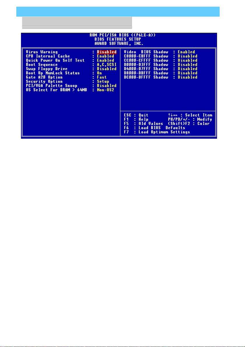
CMOS Setup Utility –
BIOS Features Setup
This section of the setup utility
allows you to configure some
system features including Virus Warning, Boot Sequence
and Security Option.
Virus Warning –
When enabled, monitors the
primary hard disk boot sector and warns of any attempt
to write to it.
Boot Sequence –
Controls the order in which
the system checks disk drives
for a boot disk.
Security Option –
Sets the level of password
protection for the system for
both the Supervisor and User
passwords.
Page 17
P6LX-A User’s Manual
2: Using Your Mainboard – 2.5
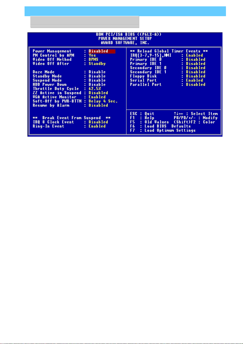
CMOS Setup Utility –
Power Management Setup
This section of the setup utility
allows you to configure the
power management features
supported by the BIOS. These
can also operate in tandem
with Operating System power
management features.
You can use the Min Saving
or Max Saving default modes
or you can configure the
power management features
individually in the User Define
mode.
Page 18

P6LX-A User’s Manual
2: Using Your Mainboard – 2.6
Hardware Features
This section is a brief overview of information about the
mainboard’s hardware features.
Onboard Ports
There are several external ports on the mainboard. These are
ports standard to most personal computers:
• COM1 Serial Port
A high-speed serial port which can also be configured as the
COM3 port in the CMOS Setup Utility.
• COM2 Serial Port (on supplied Port Bracket)
A high-speed serial port which can also be configured as the
COM4 port in the CMOS Setup Utility.
• Parallel Port
The parallel port can be configured as a Standard, ECP or EPP
parallel port in the CMOS Setup Utility
• PS/2 Keyboard Port (lower) & PS/2 Mouse Port (upper)
• USB ports – two ports (stacked)
• Game Port for joystick or other game device
• Audio connectors – Mic, Line-In & Line-Out
• Wide and Ultra Wide SCSI connectors
Connectors
There are several connectors on the mainboard for connecting
additional ports and internal peripheral devices
• IDE 1 – Primary IDE Channel
Connector for the Primary Master and Slave IDE devices.
• IDE 2 – Secondary IDE Channel
Connector for the Secondary Master and Slave IDE devices.
• Floppy Connector
Connector for two floppy disk drives.
Page 19

P6LX-A User’s Manual
2: Using Your Mainboard – 2.7
CMOS Setup Utility –
Integrated Peripherals
This section of the setup utility
configures the IDE and Floppy
controllers and the settings for
the external ports
This section enables and configures the optional USB and
Infrared features.
The SCSI features operate independent of the CMOS Setup
utility so there are no settings
for the onboard SCSI features
here
The screen illustration shows
the settings when Optimum
Settings are loaded.
Page 20

P6LX-A User’s Manual
2: Using Your Mainboard – 2.8
Case Security
The mainboard has a case security feature that will warn if the
system case or ‘chassis’ has been opened since the last time the
system was used. There is a photoelectric cell mounted on the
mainboard that is active when the system is turned off and will
detect the case being opened. The next time you turn the system
on a warning message will appear on screen during the POST
(Power On Self Test) before the Operating System loads.
The J16 connector on the mainboard connects to a chassis
intrusion signal cable.
Cooling Fan Connectors
The is a cooling fan power connector on the mainboard that
supports a CPU cooling fan with power management features. If
you connect this type of fan, and the ‘CPU F AN Off In Suspend’
line in the CMOS Setup utility’s Power Management Setup section is set to Enabled, the system will turn the fan off when the
system is in Suspend mode.
Modem Wake-Up
The J21 connector on the mainboard is for connecting a signal
cable from a modem that supports a modem ring system wakeup feature. With such a modem installed and connected to the
mainboard via this connector, the system will wake up from Suspend mode when an incoming call is received by the modem.
The ‘Ring-In Event’ line in the CMOS Setup utility’s Power
Management Setup section must be set to Enabled for this feature to function.
Page 21

P6LX-A User’s Manual
2: Using Your Mainboard – 2.9
LAN Wake-Up
The J40 connector on the mainboard is for connecting a signal
cable from a LAN card that supports a LAN wake-up feature.
When a LAN card that supports this is installed and connected to
the mainboard via this connector, the system will wake up from
Suspend mode when the system is accessed via the LAN.
ATX Power Supply
With an ATX power supply, the system will turn the power
off automatically when exiting Windows95.
UltraDMA Hard Disk Drive Support
This mainboard supports hard disks that use UltraDMA data
transfer . You attach an UltraDMA drive to one of the IDE cables.
If you use the Optimum Settings feature in the CMOS Setup
utility the system will automatically detect the drive and configure the system to use it.
CMOS Support Battery
The disk shaped battery on the mainboard is a Lithium Ion
battery that supports the small amount of onboard memory where
the CMOS Setup utility’s configuration record is stor ed. The battery will last for a number of years and can conceivably outlast
the usage period of the computer it is in.
If the battery fails, the system will not retain the CMOS Setup
configuration and the system will need to be reconfigured every
time you turn it on. If this happens, replace the battery with the
same type as is installed. You can get a replacement at many
electronics supply stores, computer stores and other places that
sell a variety of batteries for various uses.
Page 22

P6LX-A User’s Manual
2: Using Your Mainboard – 2.10
Optional Hardware Connectors
There are additional feature connectors on the mainboard for
optional ports. These require optional external port hardware.
The Onboard SCSI Connectors & Controller
The two SCSI connectors on the mainboard are controlled by
the onboard Adaptec SCSI controller. It controls both the Wide
SCSI (SCSI-2) and the Ultra Wide SCSI (SCSI-3) features.
The Wide SCSI feature uses the 50-pin connector on the main-
board and can support up to seven SCSI devices in a chain. The
ribbon cable that comes with the board has connectors for two
devices. If you want to install more than two internal SCSI devices to the Wide SCSI controller you will need a cable with more
connectors on it. If you get another cable, it can have more connectors on it than you have immediate use for. The controller
will ignore any connectors that are not connected to devices.
The Ultra Wide feature uses the 68-pin connector on the main-
board. If you want to use this feature you will need to purchase
an internal SCSI-3 cable to connect devices to the mainboard.
Software for the onboard SCSI features is on the Support Disk
that comes with the mainboard. There is also documentation that
further explains the software and how to use it.
The RAID
The RAIDport™ and onboard SCSI controller and ports are
optional hardware which are not installed on some versions of
this mainboard.
The Adaptec RAIDport™ technology is a slot extension that
extends the PCI4 slot into an expansion slot for the Adaptec ARO1130 RAID controller card. With this card installed you can set
up RAID arrays using the supported RAID levels. You can use
either or both of the onboard SCSI ports to connect hard disks
for the array.
port
™ & Onboard SCSI
Page 23

P6LX-A User’s Manual
2: Using Your Mainboard – 2.11
The Ultra Wide SCSI port will support up to fifteen devices,
the Wide SCSI port will support up to seven. If you connect an
array to one of the ports, you can still use the other port to connect other SCSI devices, for example, a SCSI CD–ROM drive.
This also allows you to configure one SCSI port as an external
port while still maintaining one port for RAID (or other) use.
The documentation that accompanies the SCSI software on
the Support Disk has further explanation of how to use the
RAIDport™ to set up a RAID array. There is also information on
the ARO-1130 RAID controller card.
External Audio & Onboard CD–ROM Audio-In Connectors
The Vibra 16X onboard audio, the external audio jacks and
the CD–ROM audio-in connectors are optional hardware which
are not installed on some versions of this mainboard.
There are three CD audio connectors on the mainboard. They
all perform the same function and you only need to use one of
them for a drive. The reason there are three connectors is to accommodate the variety of cable connectors used by CD–ROM
drive vendors.
An additional advantage is that if you have more that one CD–
ROM drive installed in your system you can attach an audio cable
to each connector, allowing you to have up to three drives connected to the onboard audio. Y ou might have to purchase a multiconnector CD–ROM audio cable to do this if the cables that come
with the extra drives you want to connect do not match the available connectors on the mainboard.
Page 24

P6LX-A User’s Manual
2: Using Your Mainboard – 2.12
IR Ports
There is one standard and one optional connector on the main-
board which support an IR (infrared) port module that enables
wireless communication between the computer and other computers and devices with an infrared port. The default IR connector, J12, is for IrDA or ASKIR infrared modules and the optional
J11 connector is for Fast IR.
The infrared port module is an optional component. If it is
installed, you must set the UART 2 line in the Integrated Peripherals section of the CMOS Setup utility to the appropriate IR
mode used by the module.
Support software and documentation for the IR port is on the
Support Disk that comes with the mainboard.
The CPU Retention Module
The Pentium II CPU requires a mounting frame that attaches
to the mainboard to guide the CPU during installation and secure
it to the mainboard. This frame is called the “retention module”
and is supplied with the mainboard. If you received this mainboard installed in a system, the retention module will already be
installed. If you purchased the mainboard to install yourself, you
will need to install the retention module on the mainboard before you install the board in a system case.
The module comes with two mounting brackets which insert
through holes in the mainboard from the underside. The module
is simple to install and will require either a flat-head or Philipshead screw driver. To install the module do as follows:
Page 25

P6LX-A User’s Manual
2: Using Your Mainboard – 2.13
1. Take precautions against static electric discharge before you
start. It is best to have an anti-static surface to place the main-
board on while you work on it and also an anti-static wrist
strap. If you don’t have an anti-static surface to work on, place
the board on the anti-static bag it comes in. If you don’t have
a wrist-strap (inexpensive and available at electronics stores),
try to touch something metal, perhaps the system case, before
you touch the mainboard.
2. The two mounting brackets insert through the mounting holes
in the mainboard. The holes are at the four corners of the Slot
1 CPU slot. Press the two mounting bolts on each bracket
through the holes in the mainboard so that they protrude
through the board. You may need to push a little to seat them.
3. The module slides over the Slot 1 CPU slot. You have to ori-
ent it correctly for it to sit flat on the mainboard. Look at the
left end of the slot (as in the mainboard illustration in Section
1). There is an orientation foot on the slot that slides into the
orientation notch on the retention module. Look at the mod-
ule and find the notch. Orient the module to the CPU slot.
4. Slide the retention module over the CPU slot. If you have it
oriented correctly it will slide on easily and sit flat on the board.
The retaining nuts mounted in the module should fit over the
mounting bolts that protrude through the mainboard.
5. Secure the retention module to the mainboard by screwing
the retaining nuts down with a screwdriver. The module should
be secure, but don’t overtighten the nuts.
There are receptacles at the top of the guide rails that the
mounting latches on the Pentium II fit into. When you install the
CPU the latches should snap into the receptacles. Follow the Intel
instructions that come with the Pentium II to install the CPU
properly.
Page 26

P6LX-A User’s Manual
2: Using Your Mainboard – 2.14
Firmware & Software
The mainboard hardware is supported by both firmware and
software components. Firmware is software that is stored on a
chip on the board rather than on disk media.
The firmware component you interface with on this main-
board is the CMOS Setup Utility. This utility establishes various
settings used by the BIOS, the basic software that is an interface
between the system hardware and software.
The software component is comprised of software drivers that
support the PCI IDE controller and some of the other hardware
features.
How To Use The CMOS Setup Utility
The CMOS Setup Utility options are listed in detail in Section
4: Reference Information. This section is just a brief explanation
of how to run the program to adjust settings as noted in this and
the next section.
To run the CMOS Setup Utility, press the Del or Delete key
while the computer is starting up, before the operating starts to
load. The utility’s main screen will appear as shown on the next
page. To navigate the program, use the controls shown on the
screen. The utility has several sections. Many of the features configured by the utility are set to operate automatically when the
‘Setup Defaults’, the recommended mode, are used. With Setup
Defaults loaded you can still customize various settings.
Clearing CMOS
Under some unusual circumstances the configuration record
created by the CMOS Setup utility and stored on the mainboard
can become corrupted and unusable, possibly leading to the board
being unable to operate properly. If this happens, the CMOS
record can be cleared by setting jumper JP3 to the clear setting for
a moment and then setting it back to the Normal setting. Refer to
Section 4 for more information.
Page 27

P6LX-A User’s Manual
2: Using Your Mainboard – 2.15
CMOS Setup Utility –
This is the main screen for the
setup utility from which you
access its various sections.
The function and use of each
section is covered in Section
4: Reference Information.
Page 28

P6LX-A User’s Manual
2: Using Your Mainboard – 2.16
Flashing The BIOS
This mainboard uses the Award BIOS. The BIOS is stored on
a programmable flash memory chip on the mainboard. Updates
to the BIOS can be installed by installing a new BIOS file on the
flash chip, which replaces the existing one. You do this using
software that comes on the Support Disk. There is an explanation of how to install a BIOS update in a ‘readme’ text file included with the program.
Bus Master Drivers
This mainboard comes with software drivers, for various Op-
erating Systems, that enable the PCI controller to operate in ‘Bus
Master’ mode. The drivers are on the Support Disk. The included
‘readme’ file has information on the drivers and installation information.
SCSI Support Software
There is a variety of support software for the onboard SCSI
and RAIDport™ features on the Support Disk that comes with
the mainboard. Software for various Operating Systems is included. The software also has documentation in each directory
to explain what it is and, where needed, how to use it.
Page 29

P6LX-A User’s Manual
3: Reconfiguring Your Mainboard – 3.1
In This Section:
Installing Expansion Cards
Adding System Memory
Installing A CPU Upgrade
Adding An IDE Peripheral
Adding SCSI Devices
Installing An AGP Card
3: Reconfiguring Your Mainboard
This section explains how to install new hardware on your
mainboard. It covers installing expansion cards, adding system
memory , changing the CPU and installing additional IDE peripheral devices such as a hard disk or a CD-ROM drive.
Installing Expansion Cards
There are seven expansion card slots on the mainboard, three
ISA slots and four PCI slots. When you get an expansion card, it
will come with instructions on how to install it, so this section
covers relevant information from the mainboard side only.
ISA Cards & Slots
ISA expansion cards often use system resources in the form of
IRQs and DMA channels. Newer cards that comply with the
Plug and Play (PnP) standard are designed to allow the Operating
System to automatically configure system resources. Cards that
do not support PnP may require manual configuration of both
the card hardware and settings in the CMOS Setup Utility.
If you have a PnP-compliant card to install there should be
little to do other than follow the installation instructions. If, however, you have a non-PnP card and it requires configuring system
resources, you may need to review the third part of this section,
Configuring Expansion Card Resources In CMOS Setup.
Page 30

P6LX-A User’s Manual
3: Reconfiguring Your Mainboard – 3.2
PCI Cards & Slots
With very few exceptions, any PCI expansion card you are
likely to get will be Plug an Play compliant. If you are using an
Operating System that supports PnP, such as Windows 95, you
should be able to follow the installation instructions that come
with the card and have the Operating System automatically recognize and configure the card.
The PCI slots on the mainboard all have ‘Bus Master’ capability. For installed PCI cards to use this feature an Operating System-specific Bus Master software driver that comes with this mainboard must be installed under your Operating System. These
drivers are located on the Support Disk.
RAIDport™ and AGP Slots
This mainboard has two other expansion slots The Adaptec
RAIDport™ slot extension and the AGP, Accelerated Graphics
Port, slot.
The Adaptec RAIDport™ slot extension to the PCI4 slot in
combination with the PCI slot forms a slot for an Adaptec ARO1130 or compatible RAID controller card for implementing any
of several supported RAID disk array schemes.
The AGP, Accelerated Graphics Port, slot is for an AGP video
display card.
Configuring Expansion Card Resources In CMOS Setup
The CMOS Setup Utility , which is covered in detail in Section
4: Reference Information, has a section called PNP/PCI Configuration. The default settings in this section allow the Operating
System to automatically configure IRQ resources for PnP compliant ISA and PCI Cards.
If you need to install a non-PnP card, you will need to configure any IRQ and DMA settings manually, both on the card and
in the CMOS Setup Utility . The following three pages show how
to do this.
Page 31
P6LX-A User’s Manual
3: Reconfiguring Your Mainboard – 3.3
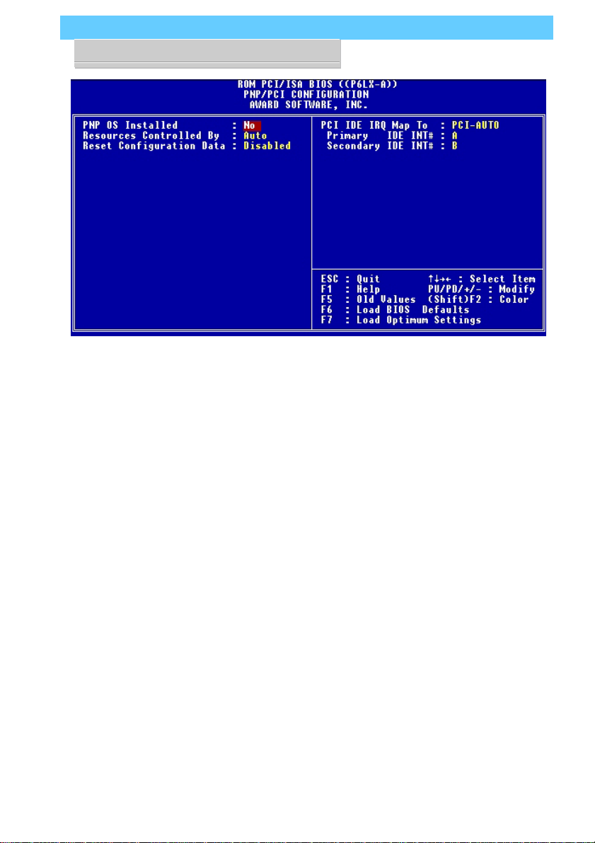
CMOS Setup Utility –
PnP/PCI Configuration
This is the default screen for
this section when Setup Defaults are loaded. If you need
to manually configure the IRQ
settings, set the first item on
the screen to the ‘Manual’
setting. See the next page.
If you install an Operating System that supports Plug and
Play, such as Windows95,
you should set the first line,
‘PNP OS Installed’ to ‘Yes’.
Running CMOS Setup
To run the CMOS Setup utility,
press the Delete or the Del
key while your computer is
first starting up. Select the
‘PNP/PCI CONFIGURATION’
item on the main screen and
press the Enter key to open it.
When you are finished, press
the Esc key once to return to
the main screen and then select ‘SAVE & EXIT SETUP’ and
press the Enter key to save the
new configuration. For more
information on this see Section 4: Reference Information.
Page 32
P6LX-A User’s Manual
3: Reconfiguring Your Mainboard – 3.4
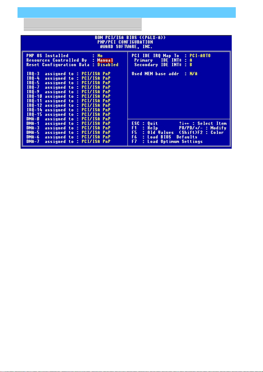
CMOS Setup Utility –
PnP/PCI Configuration
When ‘Resources Controlled
By’ is set to ‘Manual’ you can
individually configure the IRQ
& DMA channel settings. The
individual defaults are for PnP
cards and will still use all the
items listed to automatically
assign resources as needed.
If you are installing a ‘legacy’
ISA card that requires manual
configuration, you can manually assign the required resources as needed.
Legacy cards, by definition,
are not PnP compliant and
must be manually configured
if they require an IRQ or DMA
channel. See the expansion
card manual for specifics.
When an item in the list is configured this way, it is no longer
part of the pool of automatically configurable resources.
For this reason, don’t configure ISA cards this way unless
necessary.
Page 33

P6LX-A User’s Manual
3: Reconfiguring Your Mainboard – 3.5
Adding System Memory
There are some requirements you must follow if you want to
install system memory. The memory subsystem has four 168pin DIMM sockets which function independently. This mainboard supports both EDO DRAM and SDRAM (Synchronous
DRAM) modules. You can use module sizes from 8MB to 128MB,
either single or double-sided. The total supported memory capacity for this mainboard is 512MB.
If your mainboard is already installed in a system, it will have
some amount of memory installed on the board. You can tell
how much by checking the configuration screen that appears
when the computer is starting up. With some memory installed,
there may be some sockets available to add additional memory.
Memory Configurations
You can install any combination of module sizes as long as
you follow these requirements:
• All modules must use unbuffered 3.3–Volt RAM
• All EDO modules should have the same operating speed,
e.g. 60ns (nanoseconds)
• Maximum memory installation of 512MB
Other than these requirements, there is no limitation on the
variety of combinations, so they are not listed here. We recommend using one type of DRAM, either EDO or Synchronous.
SDRAM is considerably faster than EDO.
Page 34
P6LX-A User’s Manual
3: Reconfiguring Your Mainboard – 3.6
Retaining Clamp
DIMM1
DIMM2
DIMM3
DIMM4
DIMM Sockets
The picture above shows the
memory module sockets in
detail. The sockets are numbered DIMM1 to DIMM3 starting from the left socket in the
picture.
Modules press into place
and are held in position by a
retaining clamp at each end
of the socket.
When you want to remove a
module, press down on the
retaining clamps to push the
module out of the socket.
Page 35

P6LX-A User’s Manual
3: Reconfiguring Your Mainboard – 3.7
Installing Memory Modules
To install a DIMM module, look at the module and note the
position of the shorter section of the connector edge that plugs
into the DIMM socket. Note the position of the shorter section
of the socket. Orient the module so that these match and press
the module into the socket at a 90° angle. The retaining clamps at
each end of the socket will rotate upwards automatically to secure the module in place.
Modules are designed so that they will only insert in one orientation. If you have trouble inserting the connector edge of the
module into the socket, it may be oriented the wrong way. Turn
the module around and try again. You shouldn’t need to force it.
If All Sockets Are Occupied
If you want to install more memory and there are no sockets
available, you must remove some installed modules and replace
them with the upgrade modules.
If you have to do this, make sure to identify what type of
memory is already installed. In some cases, there may be a mix
of module types. You can tell this by checking the configuration
screen that appears while the computer is starting up. Press the
Pause key to temporarily interrupt the start-up process while the
screen is visible so that you have more time to read it. When
you’re done press any key to resume.
Remove the lowest performance and smallest size modules
and replace them with the upgrade.
G
SDRAM is considerably faster
than EDO DRAM. If you are
installing more memory with
some EDO already installed,
consider installing SDRAM. If
the memory already installed
is SDRAM, installing EDO
modules will hamper system
performance.
Page 36

P6LX-A User’s Manual
3: Reconfiguring Your Mainboard – 3.8
Installing A CPU Upgrade
If you are installing this mainboard it will not have a CPU
installed unless your vendor installed one when you purchased
the board. If the mainboard is installed in a system, there will
already be a CPU installed. In either case the information and
procedure for installing a CPU is the same. Since the more likely
scenario is that you are installing an upgrade, this section assumes
that is what you are doing. If you need to install the CPU Retention Module, please see Section 2.
The Basic Procedure
To install a Pentium II upgrade you need to set up the main-
board for the correct CPU speed by doing the following:
• Set the Internal Clock Factor
You configure the Internal Clock Factor by adjusting jumper
settings on the board. In order to do this, you will need to know
internal clock speed of the Pentium II you want to install.
The internal clock speed is the speed the CPU operates at to
process data and is the one used by CPU manufacturers to indicate the speed of the chip, for example, a 266MHz PentiumII
The CPU also has an external bus clock speed which is the speed
at which it interacts with external components. The external bus
clock for this mainboard is 66MHz
®
.
Configuring Internal Clock Speed & Factor
To configure the board for a CPU’s internal clock speed, you
have to set the clock factor so that the result of multiplying by
the 66MHz external bus clock is the internal clock speed of the
CPU you are installing. For example, the default setting for this
mainboard is:
66.6MHZ [external clock] x 4.0 [clock factor] =266.4MHz
or, an effective setting of 266MHz.
Since the internal clock speed the CPU is supposed to operate
at is fixed, the two factors, external clock and clock factor, are the
variables.
Page 37

P6LX-A User’s Manual
3: Reconfiguring Your Mainboard – 3.9
CPU Jumper Table & Illustrations
The next two pages show the CPU jumper settings. The settings are listed in the tables as follows:
• For a two-pin jumper, On, if the cap is in place, and Off, if the
cap is not in place.
In the jumper illustrations, the Pin 1 position is shaded and
the jumpers, shown in a “bird’s eye” view, look like this:
A jumper with a cap in position looks like this:
If you need to leave a two pin jumper open, put the cap over
one pin for safekeeping. This does not establish a setting, but
does ensure you have the cap around if you ever need it again.
C
The default settings are noted in the table.
In practice, for an Off setting
on a two-pin jumper, place
the cap over one pin so that it
doesn’t get lost.
Page 38

P6LX-A User’s Manual
3: Reconfiguring Your Mainboard – 3.10
CPU Jumper Settings
Function Jumper Settings
Internal JP1 2.0x 1-2, 3-4, 5-6, 7-8
Clock Factor 2.5x 3-4, 5-6, 7-8
3.0x 1-2,5-6, 7-8
3.5x 5-6, 7-8 (233MHz CPU)
[D] 4.0x 1-2, 3-4, 7-8 (266MHz CPU)
4.5x 3-4, 7-8 (300MHz CPU)
5.0x 1-2, 7-8 (333MHz CPU)
Note: External Bus Clock is 66MHz
JP1: Internal Clock Factor
3.5X
1
7
JP1
4.0X
JP1
2
8
1
7
2
8
4.5X
1
7
JP1
5.0X
JP1
2
8
1
7
2
8
Page 39
P6LX-A User’s Manual
3: Reconfiguring Your Mainboard – 3.11
JP1
JP3
JP5
JP6
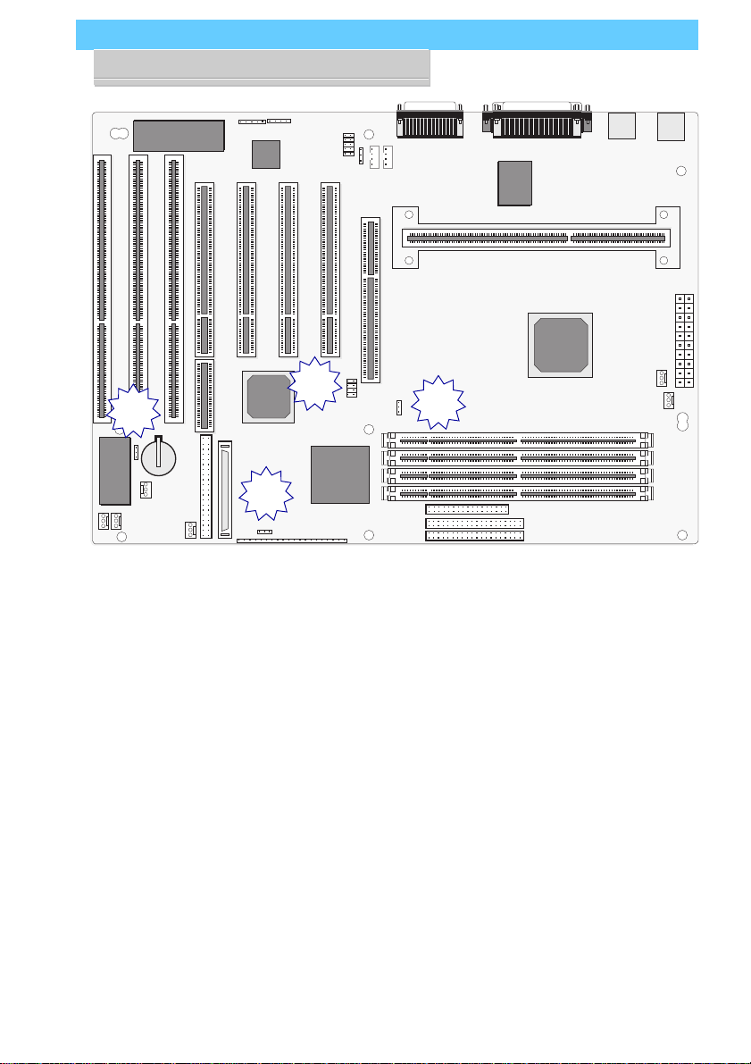
Jumper Locations
The illustration above shows
the location of the jumpers on
the mainboard.
Page 40

P6LX-A User’s Manual
3: Reconfiguring Your Mainboard – 3.12
Adding An IDE Peripheral
This section covers some aspects of installing internal IDE peripheral devices as they relate to the mainboard. The onboard
Enhanced IDE controller supports up to four devices, two per
IDE channel. The primary hard disk drive in most systems is an
IDE device. You may want to install more hard disks, a CD-ROM
drive or combination of these and other devices. This mainboard
supports both PIO and UltraDMA modes, which it can detect
automatically. You can install a mix of devices. With the Setup
Defaults loaded in the CMOS Setup utility , the system will automatically detect and configure multiple devices of whatever mode.
IDE Transfer Modes
Hard disk read and write operations are executed via the mainboard chipset. The transfer of data between the hard disk and the
system takes place using one of a number of transfer modes –
either one of several PIO modes or UltraDMA mode.
Although there are several PIO Modes (0 through 4), and this
mainboard supports all of them, most current hard disk and CDROM drives use either Mode 3 or 4. The greater the mode number, the faster the transfer rate, so you should use the fastest mode
the device can operate at. With Optimum Settings loaded in the
CMOS Setup Utility, the system will automatically detect the
fastest mode a device can use and set it for that mode.
UltraDMA is another transfer method that provides even faster
data transfer than PIO modes. To use it you must install a drive
that uses this transfer method. Drives that use PIO Mode transfer
can not use the UltraDMA setting.
The settings for drive modes are in the Integrated Peripherals
section of the CMOS Setup utility . The screen illustration at right
shows the Setup Defaults settings.
Page 41
P6LX-A User’s Manual
3: Reconfiguring Your Mainboard – 3.13
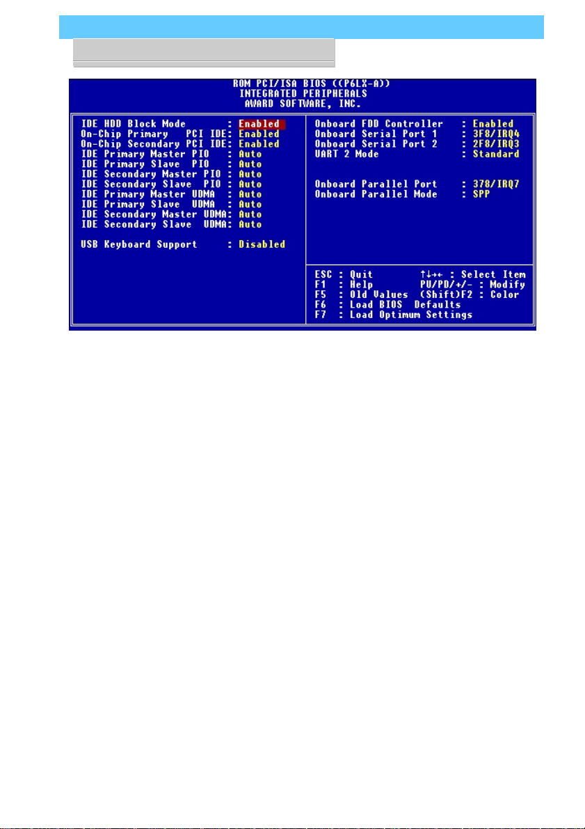
CMOS Setup Utility –
Integrated Peripherals
The illustration above shows
the Setup Defaults settings for
this screen. Y ou can install IDE
devices under these settings
and the system will automatically detect and set the best
mode for each device.
You can also set the transfer
mode for each device manually, although we recommend using the default settings unless you have a reason not to and you know what
you are doing.
Page 42

P6LX-A User’s Manual
3: Reconfiguring Your Mainboard – 3.14
Installing IDE Devices
The mainboard’s Enhanced IDE controller supports four devices in two channels, IDE1 and IDE2. These are called the Primary and Secondary IDE channels.
Each channel supports two devices, the first device is called
the Master device and the second the Slave device. You must
configure any IDE device you install to operate as one or the
other. To find out how to configure the device you plan to install
you should refer to the manual that comes with the device. You
may need to set jumpers or switches to configure it.
IDE Cables
The mainboard comes with one IDE ribbon cable to connect
two devices to the mainboard. If you need to install devices on
the second channel you will need to get another IDE cable. These
are a standard and inexpensive item that you can generally find
at any computer supply store. One edge of the cable is colored to
indicate the Pin 1 side. When you connect the cable to the mainboard and a device you must orient the cable so that this colored
edge is at the Pin 1 side of the connector you are attaching it to.
The mainboard IDE connectors have an orientation cut-out to
ensure correct orientation, and the supplied cable has an orientation tab on the side of the connector. Some IDE cables do not
have this tab and therefore are not forced to use the correct orientation. You should check that any cable you buy has orientation
tabs on the side of the connectors. If you get a cable that does not
have them, make sure the cable is correctly oriented when you
attach it to the board and the device.
IDE cables have three connectors on them, one at each end
and one in-between, closer to one of the ends. When you install
a device on the second channel, attach the lone end to the IDE2
connector on the mainboard. The two connectors that are closer
to each other are for connecting to IDE devices. The connector
on the end is for the Master device and the connector in the middle
is for the Slave device.
Page 43

P6LX-A User’s Manual
3: Reconfiguring Your Mainboard – 3.15
IDE Devices & CMOS Setup
When you install a new hard disk drive its parameters will be
automatically detected by the BIOS and entered in the Standard
CMOS Setup section of the CMOS Setup utility if you use the
Optimum Settings, which automatically detect any new hard disk
drive. All other devices do not use drive parameters and will not
show up in the device list on this page.
Adding SCSI Devices
This section is a brief overview of adding SCSI devices to a
computer system based on this mainboard. Additional information on SCSI and the support software is in text files supplied
with the SCSI support software on the Support Disk.
There are two SCSI connectors mounted on the mainboard, a
50-pin connector for Wide SCSI and a 68-pin connector for Ultra
Wide SCSI. The onboard SCSI controller supports both of them
and uses software that is provided on the Support Disk.
SCSI devices connect to the mainboard in a “daisy-chain”, that
is, in a series connected by cables between each device. If the
devices are internal, you connect devices with a ribbon cable that
has more than one device connector, such as the 50-pin Ultra
SCSI cable supplied with the mainboard.
SCSI devices can also be connected as external devices, in
which case individual external SCSI cables connect any devices
in the serial chain. You can connect external devices to this mainboard by connecting and external adapter to one of the onboard
SCSI ports. Such adapters provide an external SCSI port that
mounts in an expansion card slot opening. You then connect external SCSI devices to the external port. External SCSI port adapters can be purchased from a computer accessory vendor. You
must get an adapter specific to which SCSI connector you are
connecting to, either Wide SCSI or Ultra Wide SCSI.
Page 44

P6LX-A User’s Manual
3: Reconfiguring Your Mainboard – 3.16
SCSI Device IDs
Each SCSI connector can support up to seven SCSI devices.
Each SCSI device in the chain must have a unique identification
number to identify itself to the controller. You set the ID number
on the device hardware. There are various ways to do this so you
will need to consult the manual for any device you want to install for instructions on how to set the ID for the device.
The SCSI controller on the mainboard has an ID number, 0
(zero), so the available device ID numbers are 1 through 7 for the
Wide SCSI. SCSI-2 chain and 1 through 15 for the Ultra Wide
SCSI-3 chain.
SCSI Termination
The SCSI chain must be “terminated” at each end. The con-
nector on the mainboard is permanently terminated and there
constitutes one end of the chain. The last device in the chain,
whether it is internal or external, must also be terminated. SCSI
devices use various termination methods, so you will need to
consult the manual for the last device in the chain to see how to
terminate it.
If you connect internal SCSI devices, the device connected to
the end of the ribbon cable is the last device and must be terminated. In an external chain, the device at the end must be terminated. All devices in-between the mainboard and the last device
must not be terminated.
Installing an AGP Card
An AGP display card installs in the AGP slot on the main-
board and secures to the system case at the matching expansion
slot opening. Any AGP card will require Operating System support, which will be implemented in Windows 98 and later versions of Microsoft Windows.
Review the card documentation for any additional installa-
tion instructions.
Page 45

P6LX-A User’s Manual
4: Reference Information – 4.1
In This Section:
Jumper Summary
Connector Summary
CPU Information
Memory Configurations
CMOS Setup Utility
4: P6LX-A Reference Information
This section is a summary of the P6LX-A’s specifications and
settings.
Using This Section
The information in this section is presented in a summary format to make it easy to find specific information. If you need related explanations, please refer to the topics earlier in the manual.
Page 46

P6LX-A User’s Manual
4: Reference Information – 4.2
IR headers J11, J12
ISA 3, 2, 1
RAID
JP3
SCSI J22, J23
J40
J16
J15
J21
PCI 4,3,2,1
port
Game
Mic, Line-In, Line-Out
J25
CD-In J29, J26, J28
AGP Slot
JP5
JP1
Floppy
JP6
J9
Parallel
COM1
CPU Slot
DIMM1
DIMM2
DIMM3
DIMM4
Mouse
COM2
Keybd
USB
ATX Power
J13
J14
Secondary IDE
Primary IDE
Jumper & Connectors
The illustration above shows
the location of the jumpers,
ports and other connectors
on the mainboard.
The COM1 and COM2 ports
are underneath the Parallel
port. The USB ports and the
PS/2 ports – Keyboard (lower)
and Mouse (upper) – are
stacked vertically.
Page 47

P6LX-A User’s Manual
4: Reference Information – 4.3
Jumper Configuration & Connector Summary
This section lists the jumper setting options for this mainboard
and the onboard connectors. The settings are listed as follows:
• The two pins shorted by a jumper cap on a three-or-more-pin
jumper, e.g. 1-2
or
• For a two-pin jumper, On, if the cap is in place, and Off, if a
cap is not in place.
In the jumper illustrations, the Pin 1 position is shaded and
the jumpers, shown in a “bird’s eye” view, look like this:
A jumper with a cap in position looks like this:
The default settings are noted in the summary table.
C
In practice, for an Off setting
on a two-pin jumper, place
the cap over one pin so that it
doesn’t get lost.
Page 48

P6LX-A User’s Manual
4: Reference Information – 4.4
CPU Jumper Settings
Function Jumper Settings
Internal JP1 2.0x 1-2, 3-4, 5-6, 7-8
Clock Factor 2.5x 3-4, 5-6, 7-8
3.0x 1-2,5-6, 7-8
3.5x 5-6, 7-8 (233MHz CPU)
4.0x 1-2, 3-4, 7-8 (266MHz CPU) [D]
4.5x 3-4, 7-8 (300MHz CPU)
5.0x 1-2, 7-8 (333MHz CPU)
Note: External Bus Clock is 66MHz
Other Jumper Settings
Clear CMOS JP3 Clear 1-2*
Normal 2-3 [D]
* Put cap on jumper for a moment and then remove to clear CMOS.
SCSI Hi-Byte JP5 SCSI BIOS Controls 1-2
Always Enable 2-3 [D]
CPU Clock JP6 Normal 1-2 [D]
Turbo* 2-3
*Turbo mode sets external bus clock to 68.5MHz (not recommended for
this mainboard.)
Page 49

P6LX-A User’s Manual
4: Reference Information – 4.5
JP1: Internal Clock Factor
3.5X
JP1
1
7
4.0X
1
7
4.5X
1
7
2
8
JP1
2
8
JP1
2
8
JP3: Clear CMOS
Clear
JP3
JP6: CPU Mode
Normal
JP6
JP5: SCSI Hi-Byte
SCSI BIOS Control
Normal
JP3
Turbo
JP6
5.0X
1
7
JP1
JP5
Always Enable
2
8
JP5
Page 50

P6LX-A User’s Manual
4: Reference Information – 4.6
Onboard Connectors
Name: Function Description
J1: Keyboard Stacked PS/2 ports, keyboard lower, mouse upper
& Mouse
J3: Serial Port Two Onboard serial port is COM2, can set to COM4
J4: Serial Port One Onboard serial port is COM1, can set to COM3
J5: Parallel Port Standard 25-pin parallel Printer port
J6: Floppy Drive 34-pin connector connects to 2-device cable;
End device is Drive A:, middle is Drive B:
J7: Primary IDE 40-pin connector connects to supplied cable;
End device is Primary Master, middle is Slave
J8: Secondary IDE 40-pin connector connects to 2-device cable;
End device is Secondary Master, middle is Slave
J9: Case Features Connects to various case feature leads
Pins 1-3: Power On LED; 4-5: Suspend Switch;6-8: Suspend LED;
9-10: Reset Switch; 11-12: Keybd Lock; 13-16: Speaker; 17-18 HD LED;
19-20 Power On switch
J11: FIR header Connects to optional Fast IR infrared module cable
(optional)
J12: Intel IR header Connects to optional IrDA or ASKIR infrared module
J13: PS Fan power For ATX power supply cooling fan power cable
J14: CPU Fan power For CPU cooling fan power cable
J15: Case Fan power For case-mounted cooling fan power cable
J16: Intrusion Detector Connects to chassis intrusion detector cable
J17: Slot 1 Connector for Pentium II CPU card module
J19: AGP Slot Accelerated Graphics Port slot
Page 51

P6LX-A User’s Manual
4: Reference Information – 4.7
Name: Function Description
J20: USB Dual stacked external USB ports
J21: Modem Connects to internal modem for system wake-upon
Wake-up modem ring
J22: Wide SCSI Onboard 50-pin SCSI port connector, uses supplied
ribbon cable (optional)
J23: Ultra-Wide Onboard 68-pin SCSI port
SCSI
J24: RAID Port RAID
J25: MB-Pro Audio MB-Pro header
J26: CD-In CD-ROM drive audio cable connector – JST
J27: Audio Jacks Mic, External Line-In & Line-Out
J28: CD-In CD-ROM drive audio cable connector – Molex
J29: Aux. CD-In 4-pin CD-ROM drive audio cable connector
PS1: ATX Power Connects to 20-pin ATX power supply lead
BT1: Battery Socket for Li CMOS support battery
J40: LAN Wake-up LAN activity wake-up header
J9: Case Features Connector
1 – 3 4 – 5 6 – 8 9 – 10 11 – 12 13 – 16 17 – 18
Pin 1-3: Power On LED; Pin 4-5: Suspend Switch; Pin 6-8: Suspend LED; Pin
9-10: Reset Switch; Pin 11-12: Keyboard Lock; Pin 13-16: Speaker; Pin 17-18:
Hard Disk LED; Pin 19-20: Power Switch
port
™ connector
19 – 20
Page 52

P6LX-A User’s Manual
4: Reference Information – 4.8
The AGP Slot
The AGP (Accelerated Graphics Port) slot is for an AGP display card. With the Optimum Settings loaded in the BIOS Setup
Utility the AGP has a default memory aperture of 4MB, expandable to 256MB.
The RAID
The RAIDport™ slot extension to the PCI4 slot forms an ex-
tended slot that supports an Adaptec ARO-1130 or compatible
RAID card With the software supplied on the Support Disk this
mainboard will support the following RAID levels:
• RAID Level 0
• RAID Level 0/1
• RAID Level 5
For more information on this feature please see the documentation that accompanies the SCSI support software on the Support Disk.
portport
port
portport
™ Slot
Supported CPUs
This mainboard supports the Intel Pentium II CPU running at
the following speeds with a 66MHz external bus clock:
• 233MHz
• 266MHz
• 300MHz
• 333MHz
The CPU Retention Module
This mainboard ships with a CPU retention module which
attaches to the mainboard to provide guide rails and latch receptacles to hold the installed CPU in place. Please see Section 2,
The CPU Retention Module, if you need more information on
how to install and use the module.
Page 53

P6LX-A User’s Manual
4: Reference Information – 4.9
System Memory Specifications
The memory subsystem on this mainboard has four 168-pin
DIMM sockets. The sockets function independently and can use
either EDO DRAM or SDRAM unbuffered 3.3–Volt modules.
Single or double-sided modules from 8MB to 128MB are supported up to a total memory capacity of 512MB.
Memory Configurations
You can install any combination of module sizes as long as
you follow these requirements:
• All modules must use unbuffered 3.3–Volt RAM
• All modules have same operating speed, e.g. 60ns
Other than these requirements, there is no limitation on the
variety of combinations, so they are not listed here. We recommend using one type of DRAM, either EDO or Synchronous.
SDRAM is faster than EDO.
Page 54

P6LX-A User’s Manual
4: Reference Information – 4.10
CMOS Setup Utility Summary
This section explains the entries in the CMOS Setup Utility
program. This utility is permanently stored on the BIOS chip on
the mainboard. It creates a record of the mainboard’s and some
system configuration information and stores it in battery-supported memory on the mainboard. This record must be intact
and accurate in order for the mainboard to operate.
After a brief explanation of how to operate the utility there is
a summary of the entries and options for all sections of the utility. Under normal conditions, once your system is set up, you
should have little or no need to use this utility.
Using the CMOS Setup Utility
This mainboard uses the Award system BIOS. It is stored in a
Flash ROM memory chip on the mainboard. The BIOS uses a
software program, also stored on the same chip to create a system configuration record which is saved in a small amount of
special “CMOS” memory on the mainboard.
Accessing The CMOS Setup Utility
When you turn on your computer, a message appears on the
screen indicating you can run the Setup program by pressing the
Del key (it’s on the keypad.) The message appears after the POST
(Power On Self Test).
If you want to run Setup but you don’t respond in time before
the message disappears, you can reset the system by pressing the
Ctrl + Alt + Delete keys at the same time, or by pushing the
system Reset button. The message will then reappear.
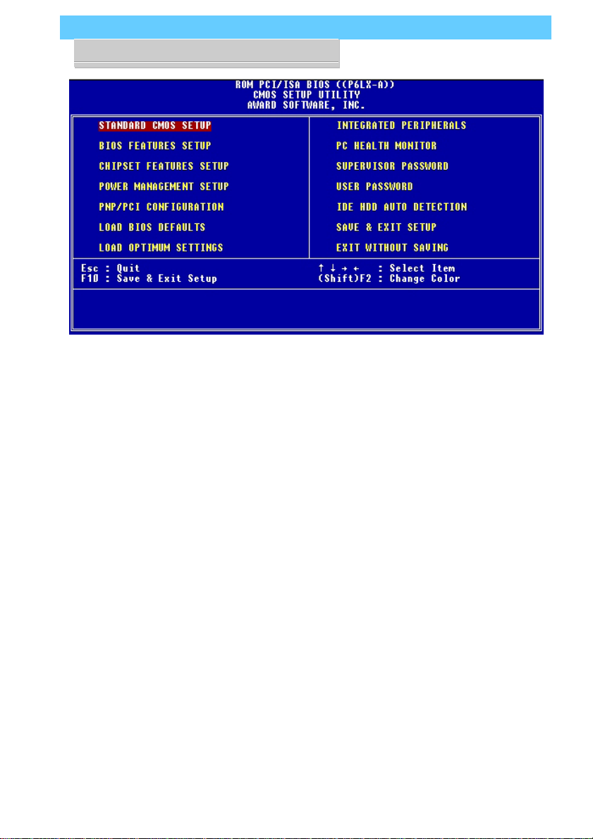
After you press the Del or Delete key the program menu screen
will appear, displaying the Setup utility section names and some
command instructions.
Page 55
P6LX-A User’s Manual
4: Reference Information – 4.11
Page 56

P6LX-A User’s Manual
4: Reference Information – 4.12
Menu Commands
If you look at the lower portion of the screen illustration you’ll
see a section that lists the control commands for this level of the
program. You execute a command by pressing the key for that
command. The program commands are :
Quit
This command will close the Setup program when you press
the ESC key.
Save & Exit Setup
This will save the current settings and close the Setup program when you press the F10 key.
Select Item
You can use the arrow keys on your keyboard to move around
the screen and select a menu item. An item is highlighted when
it is selected.
Change Color
Change the program color scheme by pressing Shift + F2.
The section at the bottom of the screen displays a brief expla-
nation of a highlighted menu item’s function.
There are six main sections to the Setup program:
• Standard CMOS Setup
Date, time, disk drive, video display and error handling
• BIOS Features Setup
System customization features and video display settings
• Chipset Features Setup
Chipset settings, memory configuration feature for special-
ized add-on cards and VGA memory configuration
• Power Management Setup
Sets up the “green” power management features
• PNP/PCI Configuration
PCI expansion slot and system resource settings
Page 57

P6LX-A User’s Manual
4: Reference Information – 4.13
• Load BIOS Defaults
Loads minimum settings from the BIOS ROM.
• Load Optimum Settings
Loads optimized settings from the BIOS ROM.
• Integrated Peripherals
Settings for the IDE channels and onboard ports
• PC Health Monitor
Monitoring sensor settings and readings, accessed by LANDesk
Client Manager
The other main menu items are affected by these items :
• Supervisor Password & User Password
Sets a system password which is configured by the Security
Option item in BIOS Features Setup.
• IDE HDD Auto Detection
Automatically detects the drive parameters of any installed
IDE hard disk drives and enters them automatically in the Standard CMOS Setup .
• Save & Exit Setup
Saves the current settings and exits the program.
• Exit Without Saving
Discards any changes made during the current session and
exits the program.
To enter a section of the Setup program, highlight the menu
item and press the Enter key.
Page 58
P6LX-A User’s Manual
4: Reference Information – 4.14
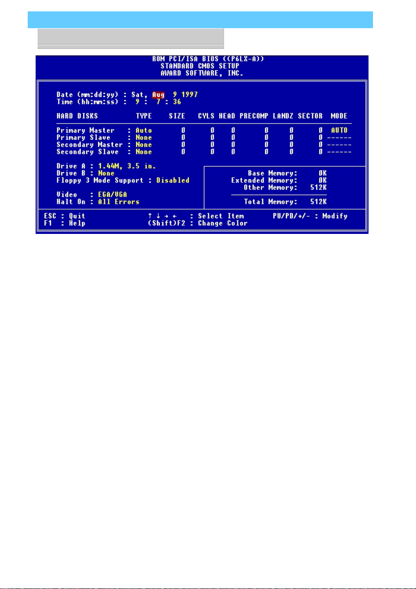
Standard CMOS Setup
To enter this section, highlight this menu item in the main
menu and press the Enter key. The screen above will appear.
Menu Commands
If you look at the lower portion of the screen illustration you’ll
see a section that lists the control commands for this level of the
program. You execute a command by pressing the key for that
command. The program commands are :
Quit
This command will close the Setup program when you press
the ESC key.
Help
This displays information about the highlighted item when
you press the F10 key.
Page 59

P6LX-A User’s Manual
4: Reference Information – 4.15
Select Item
You can use the arrow keys on your keyboard to move around
the screen and select a menu item. An item is highlighted when
it is selected.
Change Color
You can change the program color scheme by pressing Shift +
F2.
Modify
T o change the setting of a highlighted selection you can press
either the Page Up (PU) and Page Down (PD) keys or the Plus
(+) and Minus (–) keys. Pressing a key once will switch to the
next setting option for the selected item.
If your mainboard is already installed in a working system the
proper entries are already entered on this screen and you shouldn’t
change them except for adjusting the Date and Time entries if
necessary.
Date & Time
The first two lines on the screen are the date and time settings
for the system clock.
Hard Disk Type & Parameters
For an IDE hard disk drive, you should set the entries to “Auto”
and the BIOS will automatically detect all drive information
needed.
You can also use the IDE HDD Auto Detection feature, described later, to automatically enter the drive parameters of IDE
hard disk drives in these fields. If you have only SCSI hard disk
drives installed in your system leave the settings here at None.
Only hard disk information needs to be entered here. Other IDE
devices do not use this.
If you use the IDE HDD Auto Detection utility to supervise
the auto-detection process, leave the drive items set to “None”.
Y ou can also enter specifications manually by setting a line to the
“User” option.
Page 60

P6LX-A User’s Manual
4: Reference Information – 4.16
Large Hard Disk Modes
The last of the drive parameter entries – Mode – has four op-
tions, Normal, LBA, Large and Auto. The Mode settings are for
IDE hard disks only.
Normal
For IDE hard disks of 528MB or less.
LBA
This stands for Logical Block Addressing, the current standard
access mode for large IDE hard disk drives. It allows the use of
hard disks larger than 528MB by causing the IDE controller to
translate between the logical address it creates and the hard
disk’s actual physical address. The maximum drive size supported is 8.4GB.
Large
For 1GB or smaller drives with more than 1024 cylinders and
no LBA support. This access mode causes the Operating System to treat the drive as if it has fewer than 1024 cylinders by
dividing the cylinder total in half and doubling the number of
heads. Drives needing this mode are less common.
Most large IDE hard disk drives currently available use the
LBA mode. Use the AUTO setting to automatically detect the
correct mode for new drives.
Floppy Disk Drives
The two floppy disk drive items set the drive type for drives A
and B, and must be entered manually. The options are
360KB, 5.25 in.
1.2MB, 5.25 in.
720KB, 3.5 in.
1.44MB, 3.5 in.
2.88MB, 3.5 in.
None
Page 61

P6LX-A User’s Manual
4: Reference Information – 4.17
Highlight the listing after each drive name and select the appropriate entry.
Floppy 3 Mode Support
3 Mode is a Japanese 3.5-inch floppy disk drive specification.
If this type of drive is installed you should enable this feature.
The default setting is Disabled.
Video Display Types
You set this according to the type of display card in your system. This should normally be left on EGA/VGA. The options are:
EGA/VGA
Mono (for Hercules or MDA)
CGA 40
CGA 80
Error Handling
The last line – Halt On – sets when the system stops if an
error occurs. The options are:
All Errors (Default)
No Errors
All, But Keyboard
All, But Diskette
All, But Disk/Key
When you are finished in this section, exit to the main menu
screen by pressing the Esc key.
Page 62
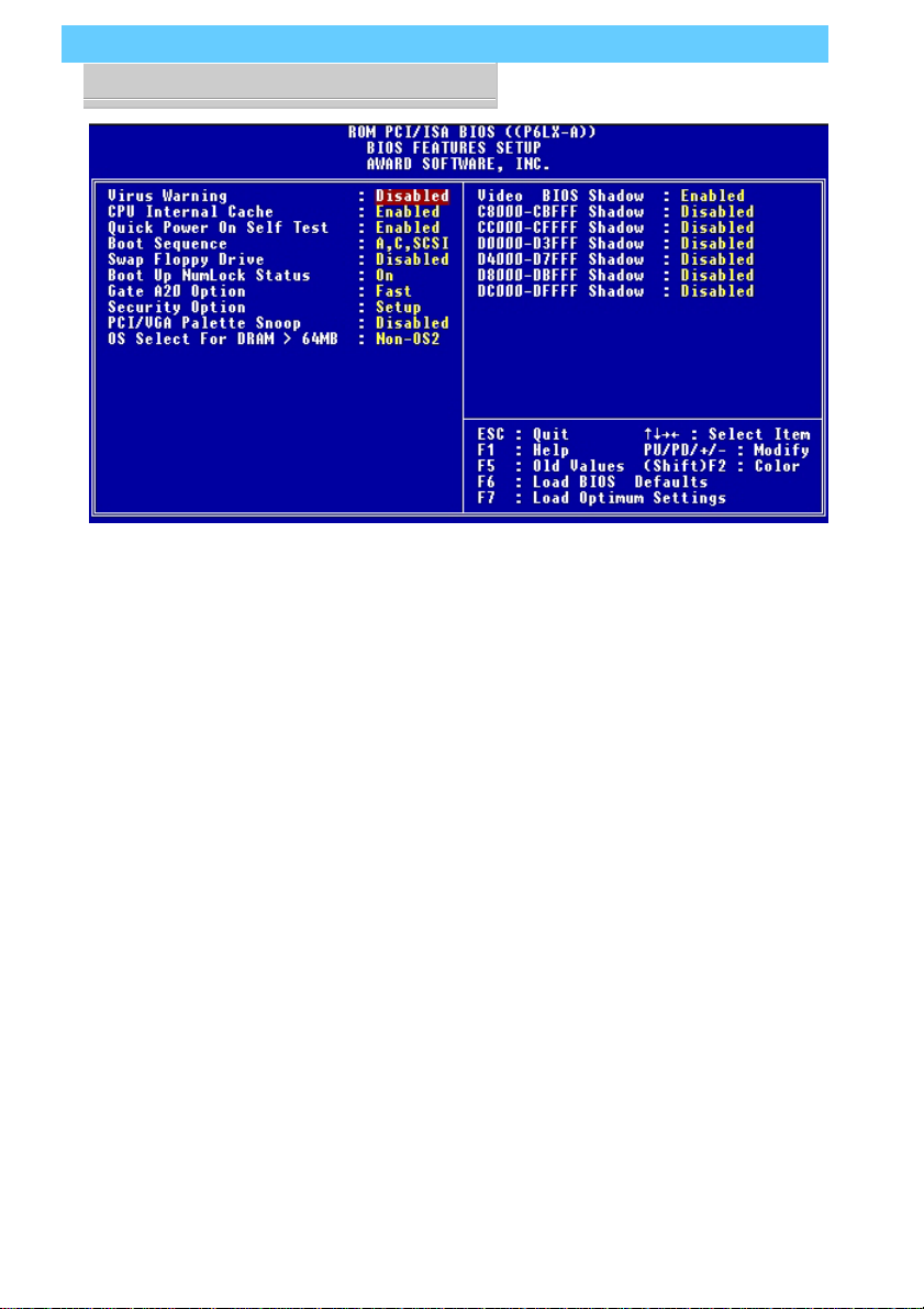
P6LX-A User’s Manual
4: Reference Information – 4.18
BIOS Features Setup
T o enter this section of the Setup program, highlight this menu
item in the main menu and press the Enter key. The following
screen will appear.
Page 63

P6LX-A User’s Manual
4: Reference Information – 4.19
Menu Commands
If you look at the lower portion of the screen illustration you’ll
see a section that lists the control commands for this level of the
program. You execute a command by pressing the key for that
command. The program commands are :
Quit
This command will close the Setup program when you press
the ESC key.
Help
This displays information about the highlighted item when
you press the F1 key.
Select Item
You can use the arrow keys on your keyboard to move around
the screen and select a menu item. An item is highlighted when
it is selected.
Modify
T o change the setting of a highlighted selection you can press
either the Page Up (PU) and Page Down (PD) keys or the Plus
(+) and Minus (–) keys. Pressing a key once will switch to the
next setting option for the selected item.
Change Color
Change the program color scheme by pressing Shift + F2.
Old Values
If you make changes during the current session and you don’t
want to keep them you can recall the last set of saved values
for this page by pressing the F5 key.
Load BIOS Defaults
Pressing F6 loads the BIOS Default settings for this page.
Load Optimum Settings
Pressing F7 loads the Optimum settings for this page.
If your mainboard is already installed in a working system the
proper entries are already entered on this screen and you shouldn’t
change them.
Page 64

P6LX-A User’s Manual
4: Reference Information – 4.20
Virus Warning
This protects the primary hard disk’s boot sector and partition
table from infection. Any attempt to write to them will halt the
system and produce a warning message. If this happens, you can
either allow the system to continue or stop it and boot from a
virus-free bootable floppy disk. Use an anti-virus utility located
on the floppy disk to check the hard disk. The default setting is
Disabled.
CPU Internal Cache
This enables CPU’s Level 1 built-in cache. Leave it enabled to
maintain system performance. The default setting is Enabled.
Quick Power On Self Test
This feature speeds up the Power On Self T est (POST) by skip-
ping some parts of the POST. If your system is functioning normally , you can enable this feature to speed the boot process. The
default setting is Enabled.
Boot Sequence
This determines the order in which the computer checks drives
for an operating system. In addition to the drive A: floppy disk
drive and the drive C: boot hard disk, you can configure the order to include another IDE hard disk drive or CD-ROM drive or
a SCSI device. The options are:
A, C, SCSI C, A, SCSI SCSI, A, C SCSI, C, A
D, A, SCSI E, A, SCSI F, A, SCSI
C, CD-ROM, A CD-ROM, C, A
C Only
Page 65

P6LX-A User’s Manual
4: Reference Information – 4.21
Swap Floppy Drive
This switches the floppy drive assignments so that drive A is
treated as drive B: and drive B: as drive A: under DOS. The default setting is Disabled.
Boot Up NumLock Status
This item allows you to select which mode the numeric keypad on an IBM-compatible extended keyboard is set to when the
computer boots up. The options are:
On – Numeric keypad mode (Default)
Off – Cursor control mode
Gate A20 Option
This sets the gate A20 control. The two options are:
Fast – Recommended default
Normal
Security Option
This sets when password protection is active. The two options are:
System – Password required at boot up
Setup – Password controls access to Setup utility
You create a password using the Password Setting option in
the main menu. With no password set, the system ignores this.
Page 66

P6LX-A User’s Manual
4: Reference Information – 4.22
PCI/VGA Palette Snoop
If your video display card has an MPEG card attached to the
feature connector, the display may invert to black on white while
booting. If this happens, set this line to Enabled to correct the
problem. The default setting is Disabled.
OS Select For DRAM >64MB
If your system has more than 64MB of system memory and
the OS/2 operating system is in use, set this to the OS2 setting.
The default setting, Non-OS2, is for all other operating systems.
Video BIOS Shadow
This copies the video display card BIOS into system DRAM
to increase display speed and is required for system performance.
The default setting is Enabled.
Shadowing Address Ranges
The next six lines, from C8000-CBFFF Shadow to DC000-
DFFFF Shadow are address ranges for shadowing other expansion card ROMs. If there are any expansion cards with ROMs
installed in your system, you have to know the address range
they use to shadow them specifically. The default setting for all
of these is Disabled.
When you are done in this section press the Esc key to return
to the main menu.
Page 67
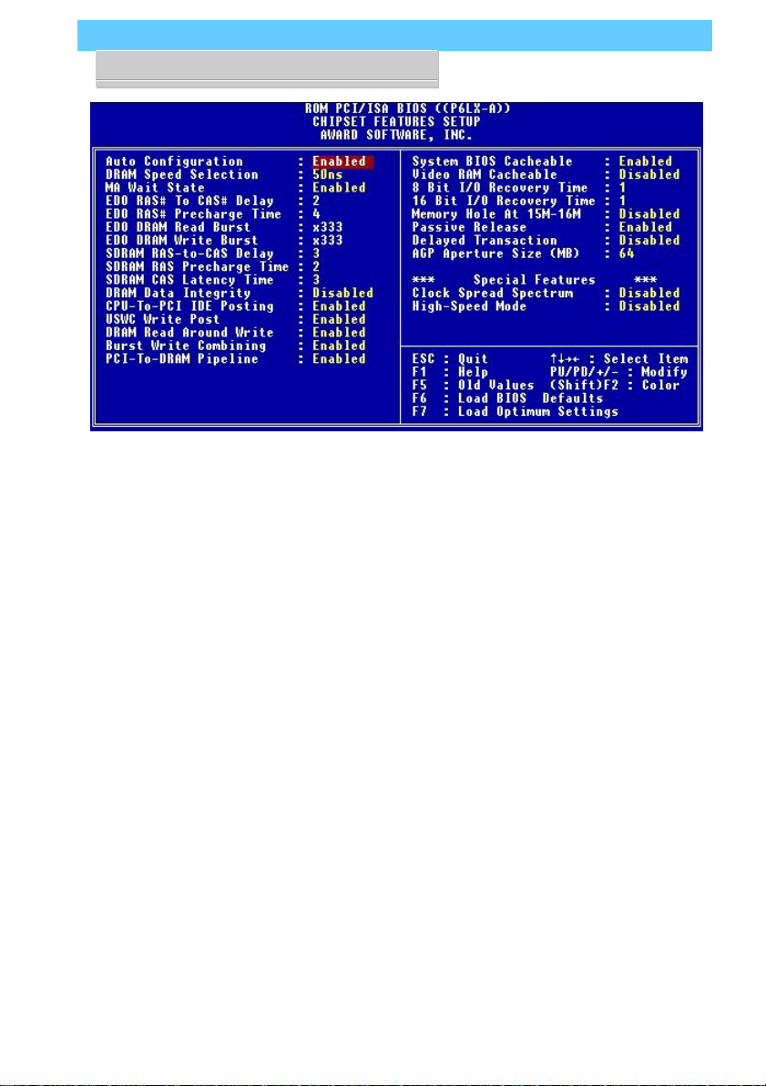
P6LX-A User’s Manual
4: Reference Information – 4.23
Chipset Features Setup
T o enter this section of the Setup program, highlight this menu
item in the main menu and press the Enter key . The screen above
will appear. Everything on this screen is either an optimum setting or set automatically when auto-configuration is active. Unless you know what you are doing, we recommend against making any manual settings in this section, with the exception of the
Memory Hole, AGP Aperture Size and Special Features items.
Menu Commands
The menu commands for this screen are the same as for the
BIOS Features Setup screen.
Auto Configuration
Auto-configuration will automatically set values in this section. If you disable auto-configuration you can set the DRAM
timing values manually. The default setting is Enabled.
Page 68

P6LX-A User’s Manual
4: Reference Information – 4.24
Memory Hole At 15M–16M
Some special add-on cards require a 1MB address space be-
tween 15 and 16MB. The documentation for this type of card
should tell you if it needs this. The default setting is Disabled.
AGP Aperture Size
This item sets the maximum amount of system memory an
AGP display card will use to store 3D texture mapping data. The
larger the aperture, the better the performance of this 3D function. The settings range from 4MB to 256MB. The default setting
is 64MB.
Special Features
If you set the two items in this section to Enabled, the external
bus clock will change to 68.5MHz, resulting in the speed of the
CPU being slightly overclocked. This provides some system performance enhancement. This feature is not recommended for use
with this mainboard. The default settings are Disabled.
To return to the main menu press the Esc key.
Page 69

P6LX-A User’s Manual
4: Reference Information – 4.25
Power Management Setup
T o enter this section of the Setup program, highlight this menu
item in the main menu and press the Enter key . The screen above
will appear.
Menu Commands
The menu commands for this screen are the same as for the
BIOS Features Setup screen.
Page 70

P6LX-A User’s Manual
4: Reference Information – 4.26
What Power Management Does
Power management lets you set up your computer to save
electricity when it is not actively in use by putting the system
into progressively greater power saving modes. In the power management scheme there are four system states which proceed in
the following sequence:
Normal
Doze
Standby
Suspend
Power Management
This controls the entire power management scheme. There
are four settings:
User Defined
You set the power saving options manually
Disable
Turns off all power management
Max Saving
Maximizes power saving by activating maximum power saving settings after one minute of system inactivity
Min Saving
Produces less power saving by activating moderate power saving settings after one hour of system inactivity
PM Control By APM
When this is set to Yes the Advanced Power Management fea-
ture in Microsoft Windows controls power management operation. The default setting is No.
Page 71

P6LX-A User’s Manual
4: Reference Information – 4.27
Video Off After
This governs when the video display gets turned off. The options are:
Suspend Off after system enters Suspend mode
Standby Off after system enters Standby mode
Doze Of f after system enters Doze mode
N/A No display shut off
Doze Mode
This sets the period of system inactivity after which the system goes into Doze mode, the most limited power saving state.
The settings range from 1 minute to 1 hour and can be set manually when power management is in User Define mode. The default setting is Disabled. When the system goes into power saving mode, power management will skip to the next mode in the
sequence if this is disabled.
Standby Mode
This sets the period of system inactivity after which the system goes into Standby mode, the intermediate power saving state.
The settings range from 1 minute to 1 hour and can be set manually when power management is in User Define mode. The default setting is Disabled. When the system goes into power saving mode, power management will skip to the next mode in the
sequence if this is disabled.
Suspend Mode
This sets the period of system inactivity after which the system goes into Suspend mode, the maximum power saving state.
The settings range from 1 minute to 1 hour and can be set manually when power management is in User Define mode. The default setting is Disabled. When the system goes into power saving mode, power management will skip to the next mode in the
sequence if this is disabled.
Page 72

P6LX-A User’s Manual
4: Reference Information – 4.28
HDD Power Down
This shuts down IDE hard disks that support a power saving
mode after a specified time period. The settings range from 1 to
15 minutes and can be set manually when power management is
in User Define mode. HDD Power Down does not affect SCSI
hard disks. The default setting is Disabled.
The system automatically resumes from any power saving
mode when there is system activity such as keyboard activity or
an IRQ wake-up event like mouse movement or a modem ring.
Throttle Duty Cycle
This line sets the percentage by which the CPU speed is cut
back when power saving initiates. The settings are:
62.5% Default
75%
87.5%
12.5%
25%
37.5%
50%
Page 73

P6LX-A User’s Manual
4: Reference Information – 4.29
ZZ Active In Suspend
This item puts the cache controller into sleep mode when the
system is in Suspend mode to achieve additional power saving.
The default setting is Disabled, the option is Enabled.
VGA Active Monitor
When this line is set to the default, Enabled, the system will
not initiate power saving while there is display activity . The other
option is Disabled.
Soft-Off By PWR-BTTN
This line controls the function of a power switch attached to
the J9 Power Push Button connector. When set to the default,
you must press the power switch for four seconds or more to
turn the system off. Pressing it for less than four seconds will put
the system into Suspend mode. If your system has a separate
Suspend switch you can set this to Instant Off and the power
switch will only function to turn the system on and off.
Delay 4 Sec. Default
Instant Off
Resume By Alarm
You can set the system to wake up at a certain date and time
by setting this line to Enabled. When enabled, two more lines
appear to allow you to set the wake-up date and time. The date
is a day within the current calendar month. The screen on the
next page illustrates this. The default setting is Disabled.
Page 74
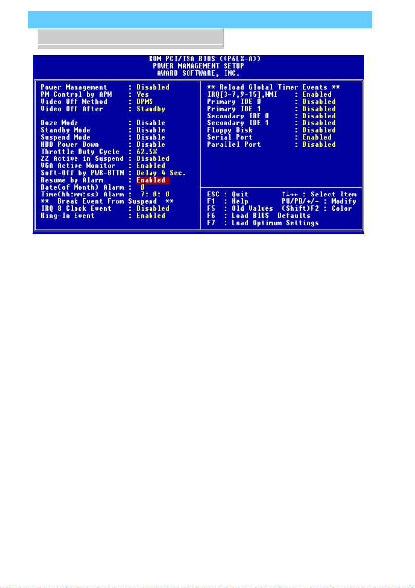
P6LX-A User’s Manual
4: Reference Information – 4.30
Break Event From Suspend
The two lines in this section control whether the system will
wake-up if either of the events noted occur. The defaults are shown
on the screen illustration on the next page.
Reload Global Timer Events
The system will restart the power saving count-down when
an event generates from any of the items in this section that are
set to Enabled. The defaults are shown above.
When you are finished in this section, press the Esc key to
return to the main menu.
Page 75

P6LX-A User’s Manual
4: Reference Information – 4.31
PNP/PCI Configuration
T o enter this section of the Setup program, highlight this menu
item in the main menu and press the Enter key. The following
screen will appear.
Menu Commands
The menu commands for this screen are the same as for the
BIOS Features Setup screen.
Page 76

P6LX-A User’s Manual
4: Reference Information – 4.32
Resources Controlled By
When this line is set to Auto the BIOS will automatically con-
figure IRQ and DMA resources. This is the recommended setting. If you set this line to Manual, the screen changes as shown
above and allows manual configuration. In general you should
only need to do this if you are installing an ISA card that requires
manual configuration.
Reset Configuration Data
The default setting is ‘Disabled’. If you need to clear the ESCD
data, set this to ‘Enabled’. The data will clear automatically and
the BIOS will reset this line to the ‘Disabled’ setting.
Page 77

P6LX-A User’s Manual
4: Reference Information – 4.33
PCI IDE IRQ Map To
Most of PCI IDE cards are non-PCI compliant. This line defines the IRQ Routing to make them work properly. The available settings are:
PCI-AUTO (default)
ISA
PCI-SLOT1
PCI-SLOT2
PCI-SLOT3
PCI-SLOT4
If you set this option to ‘ISA’, both the ‘Primary IDE INT#’
and ‘Secondary IDE INT#’ options below it will not appear on
the screen.
Primary/Secondary IDE INT#
These define the primary/secondary IDE INT# of a PCI IDE
card. The setting options are:
A (Primary IDE INT# default )
B (Secondary IDE INT# default )
C
D
When you are finished you can press the Esc key to return to
the main menu.
Page 78

P6LX-A User’s Manual
4: Reference Information – 4.34
Load BIOS Defaults
T o use this command highlight it in the main menu and press
Enter. A message will appear asking if you want to load the BIOS
Defaults. Press the Y key and then the Enter key. The BIOS default settings will load. Press the N key if you want to cancel.
This loads a set of troubleshooting default values permanently
stored in the BIOS ROM. The settings are not optimal and turn
off all the performance features. Standard CMOS Setup is not
affected by this command.
Load Optimum Settings
T o use this command highlight it in the main menu and press
Enter. A message will appear asking if you want to load the Optimum Settings. Press the Y key and then the Enter key . The optimum default settings will load. Press the N key if you want to
cancel.
This loads a set of optimized default values permanently stored
in the BIOS ROM. Use this command to load default settings for
normal system operation. Standard CMOS Setup is not affected
by this command.
Page 79
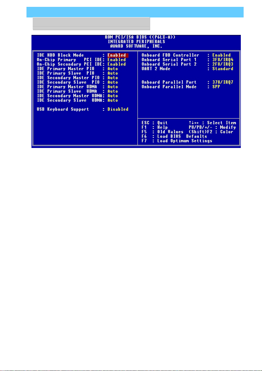
P6LX-A User’s Manual
4: Reference Information – 4.35
Integrated Peripherals
This section sets the IDE transfer mode for all IDE channels. It
also configures the other onboard ports.
Menu Commands
The menu commands for this screen are the same as for the
BIOS Features Setup screen.
Page 80

P6LX-A User’s Manual
4: Reference Information – 4.36
IDE HDD Block Mode
Enables hard disk drive block transfer mode . The setting op-
tions are:
Enabled (default)
Disabled
On-Chip Primary/Secondary PCI IDE
Enables or Disables the Primary or Secondary PCI controllers.
Selecting “Disabled”
Secondary).
Enabled (default)
Disabled
IDE Primary/Secondary Master/ Slave PIO
These four lines set the hard disk PIO transfer mode, which
affects the hard disk data transfer rate. The system will autodetect the PIO mode of a device in any of these positions when
they are set to ‘Auto’, the recommended setting. Alternatively,
you can set the mode manually. Modes 0 to 4 are supported.
releases IRQ14 ( for Primary) or IRQ15 (for
Primary/Master Master/Slave UltraDMA
These four lines enable hard disk UltraDMA transfer mode,
which requires a drive that supports this data transfer method.
The system will auto-detect an UltraDMA device in any of these
four positions when they are set to ‘Auto’, the recommended
setting. The other setting is ‘Disabled’. You can leave these set to
Auto without effect if there are no UltraDMA devices installed.
USB Keyboard Support
Enables or Disables support for a USB keyboard. Enable this if
you connect a USB keyboard. The default is Disabled.
Page 81

P6LX-A User’s Manual
4: Reference Information – 4.37
Onboard FDD Controller
Enables or Disables the onboard Floppy Drive controller.
Onboard Serial Port 1/2
Sets the I/O address for serial ports 1 & 2.
3F8/IRQ4 Onboard serial port COM1 default
2F8/IRQ3 Onboard serial port COM2 default
3E8/IRQ4
2E8/IRQ3
Disabled
UART 2 Mode
Sets mode for the second serial port UART . If you select an IR
module type, the second serial port will not be available. The
setting options are:
Standard (default) – (used by COM2 serial port)
ASKIR
HPSIR
The infrared mode you select here should be the same as the
infrared module you are connected to the mainboard. You can
also manually configure the Duplex, RxD and TxD settings if the
defaults are not correct for the installed module. See the screen
illustration on the next page.
Page 82

P6LX-A User’s Manual
4: Reference Information – 4.38
Onboard Parallel Port
Sets the I/O address for the onboard parallel port. The setting
options are:
378H/IRQ7 (default)
Disabled
278H/IRQ5
3BCH/IRQ7
If you set this option to ‘Disabled’, the next option, ‘Onboard
Parallel Mode’,
will not appear on the screen.
Page 83

P6LX-A User’s Manual
4: Reference Information – 4.39
Onboard Parallel Mode
Selects the parallel port mode. The setting options are:
SPP (default)
ECP/EPP
EPP/SPP
ECP
If you set this option to ‘SPP’ or ‘EPP/SPP’, the ‘ECP Mode
Use DMA’ option will not appear on the screen. If you set this
option to ‘SPP’ or ‘ECP’, the ‘Parallel Port EPP Type’ option will
not appear on the screen.
ECP Mode Use DMA
Selects the ECP Mode DMA channel. The setting options are:
3 (default)
1
Parallel Port EPP Type
Sets the EPP protocol version. The setting options are:
EPP 1.7 (default)
EPP 1.9
Page 84

P6LX-A User’s Manual
4: Reference Information – 4.40
PC Health Monitor
T o enter this section of the Setup program, highlight this menu
item in the main menu and press the Enter key.
Menu Commands
The menu commands for this screen are the same as for the
BIOS Features Setup screen.
What The Health Monitor Does
This section of the CMOS Setup utility is connected to the
sensor technology on the mainboard. The sensor monitors the
voltage and temperature status for the items listed on the screen.
There are two sections on the screen, Warning Messages and
PC Status. The Warning Messages section has settings that control the monitoring function. The PC Status section displays the
current status of the listed items as detected by the onboard sensor, including voltage readings and temperatures.
Warning Messages
This section of the screen lists the items monitored by the
sensor and enables warning messages which appear during the
POST (Power On Self Test), which runs when your computer is
starting up. If the sensor detects a condition outside safe parameters during start-up, it will generate a warning message.
You can set the expected core voltage for the CPU under CPU
Voltage. The options for the rest of the items listed are Enabled
and Disabled.
Page 85

P6LX-A User’s Manual
4: Reference Information – 4.41
The monitored items and default settings are:
**** Warning Messages ****
CPU Core Voltage Enabled
Vcc3 Voltage (3.36V) Enabled
Vcc2 Voltage (2.5V) Enabled
Vcc Voltage (5V) Enabled
+12V Voltage Enabled
–12V Voltage Enabled
–5V Voltage Enabled
CPU Fan Disabled
Power Fan Disabled
Mainboard Temperature Enabled
Chassis Enabled
PC Status
When you call up the PC Health Monitor screen this section
displays the current readings from the onboard sensor. The readings are for the same items as in the Warning Message list.
The last line, System Status indicates the current evaluation of
the system state in terms of the monitored items listed. Under
normal conditions it will display ‘OK!’ as the system status. If
there is a problem a warning will appear.
Page 86

P6LX-A User’s Manual
4: Reference Information – 4.42
Supervisor & User Password Settings
To use either of these commands, highlight one in the main
menu and press Enter. A message will appear prompting you to
enter a password.
Type in a password. The password is case sensitive, and can
be up to 8 alphanumeric characters. Press Enter when you finish
typing in the password.
If you typed in a password, the message “Confirm Password”
will appear. Confirm the password by typing it again and pressing Enter. The message box will close.
If you decide you don’t want to set a password after you acti-
vate this command, or if you want to eliminate an existing password, press Enter without typing anything else. The message
“Password Disabled” will appear and the message box will close.
When you set a password, the Security Option line in BIOS
Features Setup controls when the password is required. You can
set the option to require the password when the system boots up
or when calling up the CMOS Setup utility . The mainboard ships
with no password.
IDE HDD Auto Detection
When you install an IDE hard drive, you can use this feature
to automatically detect the drive parameters and enter them in
the appropriate Hard Disk section of Standard CMOS Setup.
However, since the Auto settings in Standard CMOS Setup perform the same function, you do not need to configure IDE hard
disk drives from here. If you want to use this feature, highlight it
in the main menu and press the Enter key.
Save And Exit Setup
When you select this and press Enter the values entered dur-
ing the current session are recorded in CMOS memory.
Exit Without Saving
When you select this and press Enter the Setup Utility closes
without recording any changes made during the current session.
 Loading...