

Page 1

i
Motherboard User’s Guide
This publication, including photographs, illustrations and software, is under the
protection of international copyright laws, with all rights reserved. Neither this
user’s guide, nor any of the material contained herein, may be reproduced without
the express written consent of the manufacturer.
The information in this document is subject to change without notice. The manufacturer makes no representations or warranties with respect to the contents hereof
and specifically disclaims any implied warranties of merchantability or fitness for
any particular purpose. Further, the manufacturer reserves the right to revise this
publication and to make changes from time to time in the content hereof without
obligation of the manufacturer to notify any person of such revision or changes.
Trademarks
IBM, VGA, and PS/2 are registered trademarks of International Business Machines.
Intel, Pentium/II/III, Pentium 4, Celeron and MMX are registered trademarks of
Intel Corporation.
Microsoft, MS-DOS and Windows 98/ME/NT/2000/XP are registered trademarks
of Microsoft Corporation.
AMI is a trademark of American Megatrends Inc.
It has been acknowledged that other brands or product names in this manual are
trademarks or the properties of their respective owners.
Static Electricity Precautions
1. Don’t take this motherboard and components out of their original staticproof package until you are ready to install them.
2. While installing, please wear a grounded wrist strap if possible. If you
don’t have a wrist strap, discharge static electricity by touching the bare
metal of the system chassis.
3. Carefully hold this motherboard by its edges. Do not touch those components unless it is absolutely necessary. Put this motherboard on the top of
static-protection package with component side facing up while installing.
Pre-Installation Inspection
1. Inspect this motherboard whether there are any damages to components
and connectors on the board.
2. If you suspect this motherboard has been damaged, do not connect power
to the system. Contact your motherboard vendor about those damages.
Copyright © 2007
All Rights Reserved
P17G/1333 Series, V1.0A
August 2007
Page 2

ii
Motherboard User’s Guide
Table of Contents
Trademarks .......................................................................................................... i
Static Electricity Precautions ......................................................................................... i
Pre-Installation Inspection ............................................................................................. i
Chapter 1: Introduction ..................................................................................... 1
Key Features .................................................................................................................... 1
Package Contents ........................................................................................................... 4
Chapter 2: Motherboard Installation .............................................................. 5
Motherboard Components ............................................................................................ 6
I/O Ports .......................................................................................................................... 8
Installing the Processor ................................................................................................. 9
Installing Memory Modules ........................................................................................1 0
Jumper Settings ............................................................................................................ 1 4
Install the Motherboard ............................................................................................... 1 5
Connecting Optional Devices .....................................................................................1 6
Install Other Devices ....................................................................................................1 8
Expansion Slots ............................................................................................................ 2 0
Chapter 3: BIOS Setup Utility ....................................................................... 22
Introduction .................................................................................................................. 2 2
Running the Setup Utility ............................................................................................ 2 2
Standard CMOS Setup Page ....................................................................................... 2 3
Advanced Setup ............................................................................................................ 2 5
Advanced Chipset Setup .............................................................................................. 2 6
Integrated Peripherals ................................................................................................. 2 7
Power Management Setup .......................................................................................... 2 8
PCI/PnP Configuration ............................................................................................... 2 9
PC Health Status ..........................................................................................................3 0
Frequency/Voltage Control ...............................................................................31
Load Optimal Defaults ................................................................................................ 3 2
Supervisor Password ....................................................................................................3 2
User Password ................................................................................................. 33
Save & Exit Setup ........................................................................................... 34
Exit Without Saving ......................................................................................... 34
Chapter 4: Software & Applications .............................................................. 35
Introduction .................................................................................................................. 3 5
Installing Support Software ........................................................................................3 5
Bundled Software Installation .................................................................................... 3 7
Page 3
iii
Motherboard User’s Guide
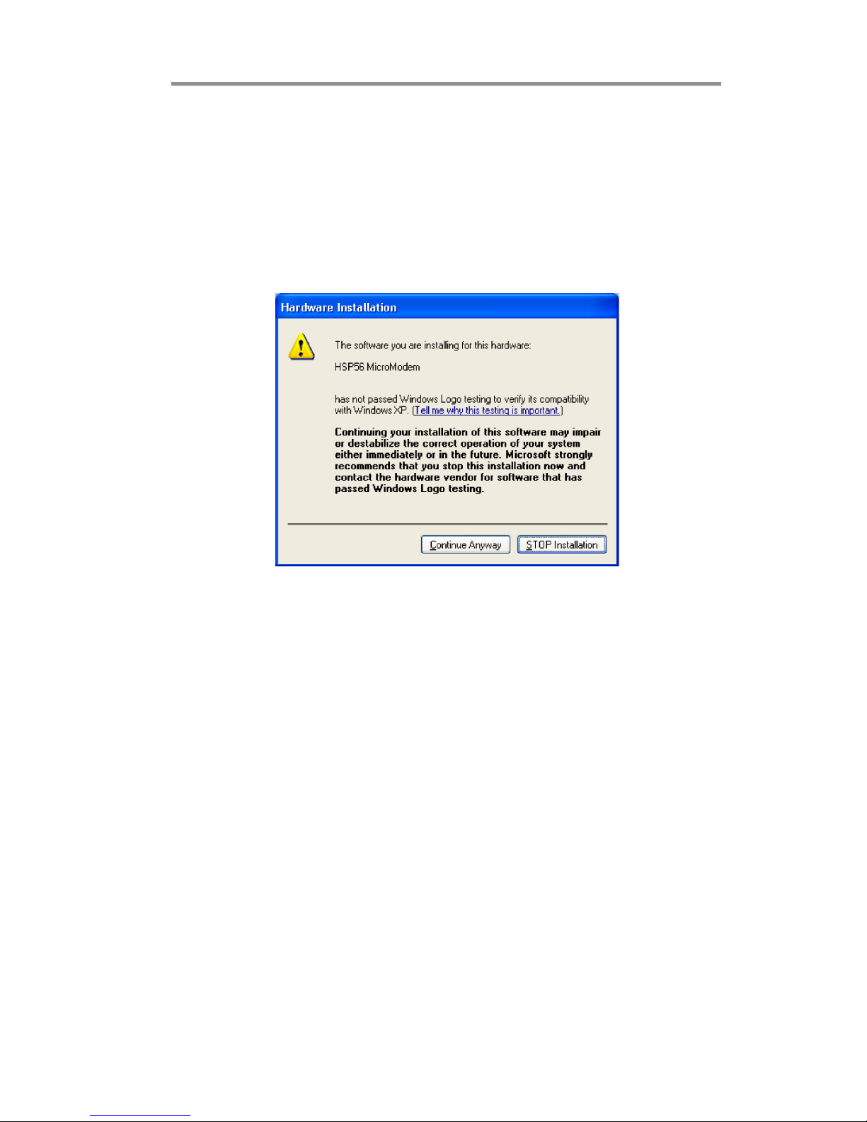
Notice:
Owing to Microsoft’s certifying schedule is various to every supplier, we might
have some drivers not certified yet by Microsoft. Therefore, it might happen under
Windows XP that a dialogue box (shown as below) pop out warning you this
software has not passed Windows Logo testing to verify its compatibility with
Windows XP. Please rest assured that our RD department has already tested and
verified these drivers. Just click the “Continue Anyway” button and go ahead the
installation.
Page 4

1
Chapter 1: Introduction
Chapter 1 Introduction
This motherboard has a LGA 775 socket for latest Intel® Core
TM
2 Duo/Celeron
®
D processors with Hyper-Threading Technology and Front-Side Bus (FSB)
speeds up to 1333/1066/800/533 MHz. Hyper-Threading Technology, designed to
take advantage of the multitasking features gives you the power to do more things
at once.
This motherboard integrates the 945GC Northbridge along with Intel I/O Con-
troller Hub 7 (ICH7) that supports the Serial ATA interface for high-performance and mainstream desktop PCs; the built-in USB 2.0 providing higher bandwidth and implementing Universal Serial Bus Specification Revision 2.0.
It supports 6-channel High Definition Audio Codec and provides one IDE Ultra
ATA 100/66/33 channel. It has one PCIEX16 slot and two 32-bit PCI slots. There
is a full set of I/O ports including two PS/2 ports for mouse and keyboard, one serial
port, one optional LAN port, one VGA port, audio jacks for microphone, line-in
and line-out, and four back-panel USB 2.0 ports. In addition, onboard USB headers
provide extra ports by connecting the extended USB module to the motherboard.
It is an Micro ATX motherboard and has power connectors for a ATX power
supply.
Key Features
The key features of this motherboard include:
LGA775 Socket Processor Support
• Supports the latest Intel® Core
TM
2 Duo/ Celeron® D processors with
Hyper-Threading Technology
• Supports up to 1333/1066/800/533 MHz Front-Side Bus
Chipset
There are 945GC Northbridge and Intel I/O Controller Hub 7 (ICH7) in the
chipsets in accordance with an innovative and scalable architecture with proven
reliability and performance.
Note: 1. Hyper-Threading technology enables the operating system into thinking
it’s hooked up to two processors, allowing two threads to be run in parallel,
both on separate ‘logical’ processors within the same physical processor.
• Hyper-Threading Technology
2. Under ECS validation, this motherboard is able to support FSB 1333
MHz.
Page 5

2
Motherboard User’s Guide
Onboard IDE connector
• One IDE connector that supports PIO (Programmable Input/Output)
and DMA (Direct Memory Access) modes
• Supports IDE Ultra DMA bus mastering with transfer rates of 100/66/33
MB/sec
• System Memory Controller Support
-Supports DDR2 SDRAM with up to maximum memory of 2 GB
• PCI Express Graphics Interface Support
-One PCIEX16 slot for Graphic Interface
• PCI Bus Interface
-Supports PCI Revision 2.3 Specification at 33 MHz
• Integrated Serial ATA Host Controller
-Supports four ports with data transfer rate up to 3.0 Gb/s
• Integrated IDE Controller
-Ultra ATA 100/66/33 Support
• USB 2.0
-Integrated USB 2.0 Host Controller supporting up to eight USB 2.0
ports
rates
• Low pin count for both host and devices
Serial ATA
• Four Serial ATA Connectors
• Transfer rate exceeding best ATA (~3.0 Gb/s) with scalability to higher
• 5.1 Channel High Definition Audio Codec
• All DACs support 192K/96K/48K/44.1KHz sample rate
• Software selectable 2.5V/3.75V VREFOUT
• Meets Microsoft WHQL/WLP 2.x audio requirements
• Direct Sound 3D
TM
compatible
Audio
Memory Support
• Two DIMM sockets for DDR2 667/533/400 DDR SDRAM with Dual-
channel architecture
• Maximum installed memory is 2 GB
Expansion Slots
• One PCIEX16 slot for Graphic Interface
• Two 32-bit PCI v2.3 compliant slots
• One 40-pin IDE connector that supports two IDE devices
• One floppy disk drive interface
• Four 7-pin SATA connectors
Page 6

3
Chapter 1: Introduction
• Two PS/2 ports for mouse and keyboard
• One serial port
• One VGA port
• Four USB ports
• One LAN port (optional)
• Audio jacks for microphone, line-in and line-out
Onboard I/O Ports
• Integrated 10/100/1000 transceiver
• Supports PCI v2.3, 32-bit, 33/66 MHz
• Supports Wake-On-LAN (WOL) function and remote wake-up
• Supports 10/100 Mb/s N-Way Auto negotiation operation
• Half/Full duplex capacity
• Supports Wake-On-LAN (WOL) function and remote wake-up
The onboard LAN controller provides the following features:
Onboard LAN (optional)
• Power management
• Wake-up alarms
• CPU parameters and memory timing
• CPU and memory timing
The firmware can also be used to set parameters for different processor clock
speeds.
BIOS Firmware
This motherboard uses AMI BIOS that enables users to configure many system
features including the following:
Page 7

4
Motherboard User’s Guide
Optional Accessories
You can purchase the following optional accessories for this motherboard.
The Extended USB module
The Serial ATA cable
Note: You can purchase your own optional accessories from the third party,
but please contact your local vendor on any issues of the specification
and compatibility.
Package Contents
Your motherboard package ships with the following items:
The motherboard
The User’s Guide
One diskette drive ribbon cable (optional)
One IDE drive ribbon cable
The Software support CD
Dimensions
• Micro ATX form factor of 244 x 210 mm
Note: Hardware specifications and software items are subject to change
without notification.
Page 8

5
Chapter 2: Motherboard Installation
Chapter 2 Motherboard Installation
To install this motherboard in a system, please follow these instructions in this
chapter:
Identify the motherboard components
Install a CPU
Install one or more system memory modules
Make sure all jumpers and switches are set correctly
Install this motherboard in a system chassis (case)
Connect any extension brackets or cables to headers/connectors on the
motherboard
Install peripheral devices and make the appropriate connections to head-
ers/connectors on the motherboard
Note: 1
2 Never connect power to the system during installation; otherwise, it
may damage the motherboard.
Before installing this motherboard, make sure jumper CLR_CMOS is
under Normal setting. See this chapter for information about locating
CLR_CMOS and the setting options.
Page 9
6
Motherboard User’s Guide
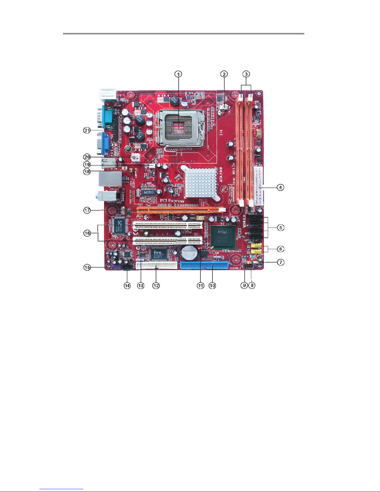
Motherboard Components
Page 10

7
Chapter 2: Motherboard Installation
ITEM LABEL COMPONENTS
1CPU Socket
LGA775 Socket for Intel
®
Core™2 Duo/
Celer on
®
D CPUs
2 CPU_FAN CPU cooling f an connector
3 DIMM1/2 240-pin DDR2 SDRAM slots
4 ATX1 Standard 24-Pin ATX Pow er connector
5 SATA1~4 Serial ATA connectors
6 F_USB1~2 Front Panel USB headers
7 SPK1 Speaker header
8 USBPWR_F Front Panel USB Pow er Select Jumper
9 F_PANEL1 Front panel sw itch/LED header
10 IDE1 Primary IDE connector
11 CL R_CMOS Clear CMOS jumper
12 FDD Floppy Disk Drive connector
13 SPDIFO1 SPDIF out header
14 CD_IN1 Analog audio input connecor
15 F_AUDIO1 Front Panel Audio header
16 PCI1~2 32-bit add-on card slots
17 PCIEX16 PCI Express slot f or graphics interf ace
18 USBPWR_R Rear Panel USB PS/2 Pow er Select Jumper
19 SY S_FA N Sy s t em Fan c onnector
20 ATX12V1 4-pin +12V pow er connector
21 LPT1 Parallel port header
Page 11
8
Motherboard User’s Guide
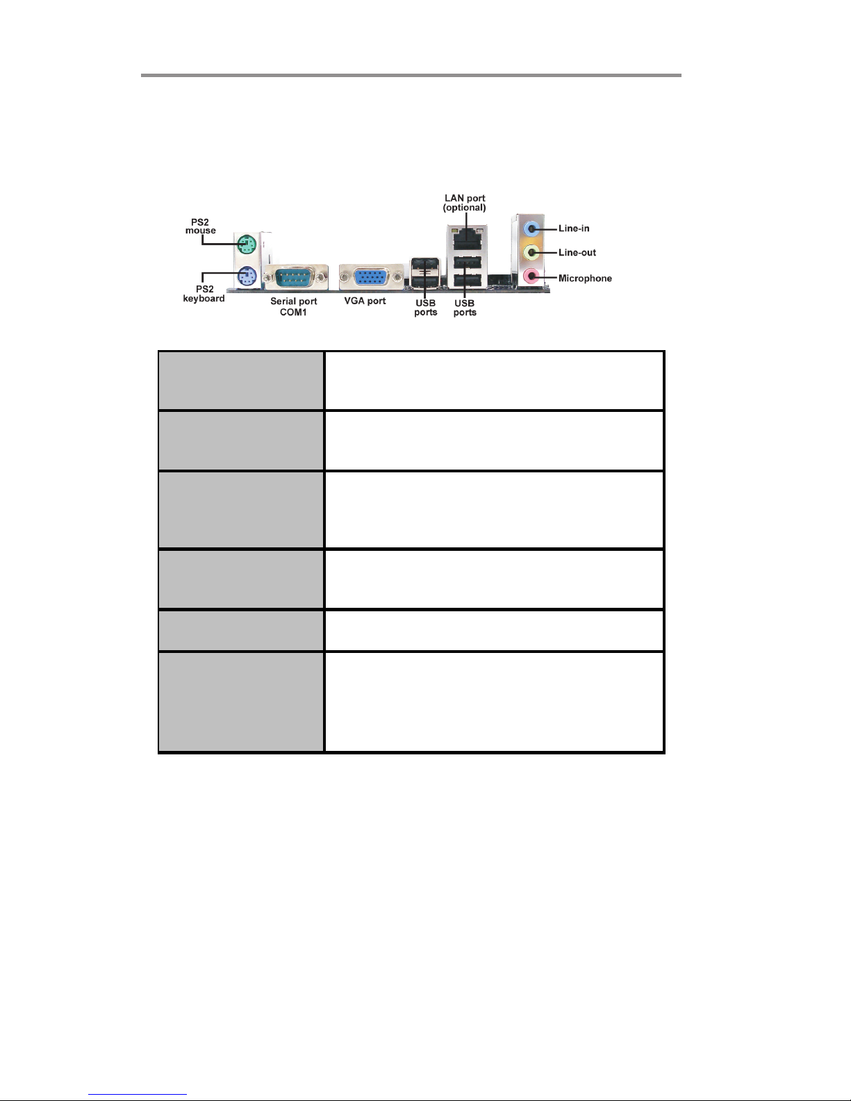
I/O Ports
The illustration below shows a side view of the built-in I/O ports on the
motherboard.
PS2 Mouse
Use the upper PS/2 port to connec t a PS/2 pointing
device.
PS2 Keyboard
Use the low er PS/2 port to connect a PS/2
keyboard.
Ser ial Por t ( COM1)
Use the COM port to connect serial devices such
as mice or fax/modems. COM1 is identified by the
system as COM1.
LAN Port (optional)
Connect an RJ-45 jack to the LAN port to connect
your computer to the Network.
USB Po r t s
Use the USB ports to connect USB devices.
Audio Ports
Use the three audio ports to connect audio
devices. The first jack is f or stereo line-in signal.
The second jack is for stereo line-out signal. The
third jack is f or microphone.
Page 12
9
Chapter 2: Motherboard Installation
This motherboard has a LGA775 socket for the latest Intel® Core
TM
2 Duo/
Celeron® D processors. When choosing a processor, consider the performance
requirements of the system. Performance is based on the processor design, the
clock speed and system bus frequency of the processor, and the quantity of internal cache memory and external cache memory.
This motherboard automatically determines the CPU clock frequency and system bus
frequency for the processor. You may be able to change these settings by making
changes to jumpers on the motherboard, or changing the settings in the system Setup
Utility. We strongly recommend that you do not over-clock processors or other
components to run faster than their rated speed.
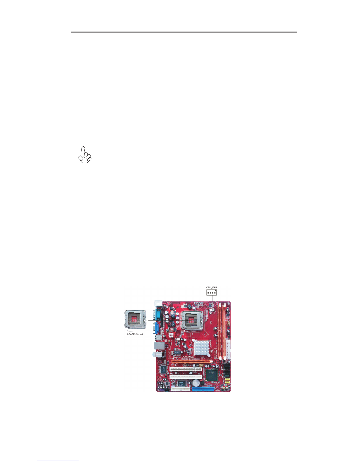
Installing the Processor
CPU Installation Procedure
Follow these instructions to install the CPU:
Warning: Over-clocking components can adversely affect the reliability
of the system and introduce errors into your system. Over-clocking can
permanently damage the motherboard by generating excess heat in
components that are run beyond the rated limits.
Fail-Safe Procedures for Over-clocking
When end-users encounter failure after attempting over-clocking, please take the
following steps to recover from it.
1. Shut down the computer.
2. Press and hold the “Page Up Key (PgUp)” of the keyboard, and then boot the PC
up.
3. Two seconds after the PC boots up, release the “Page Up Key (PgUp)”.
4. The BIOS returns to the default setting by itself.
Page 13
10
Motherboard User’s Guide
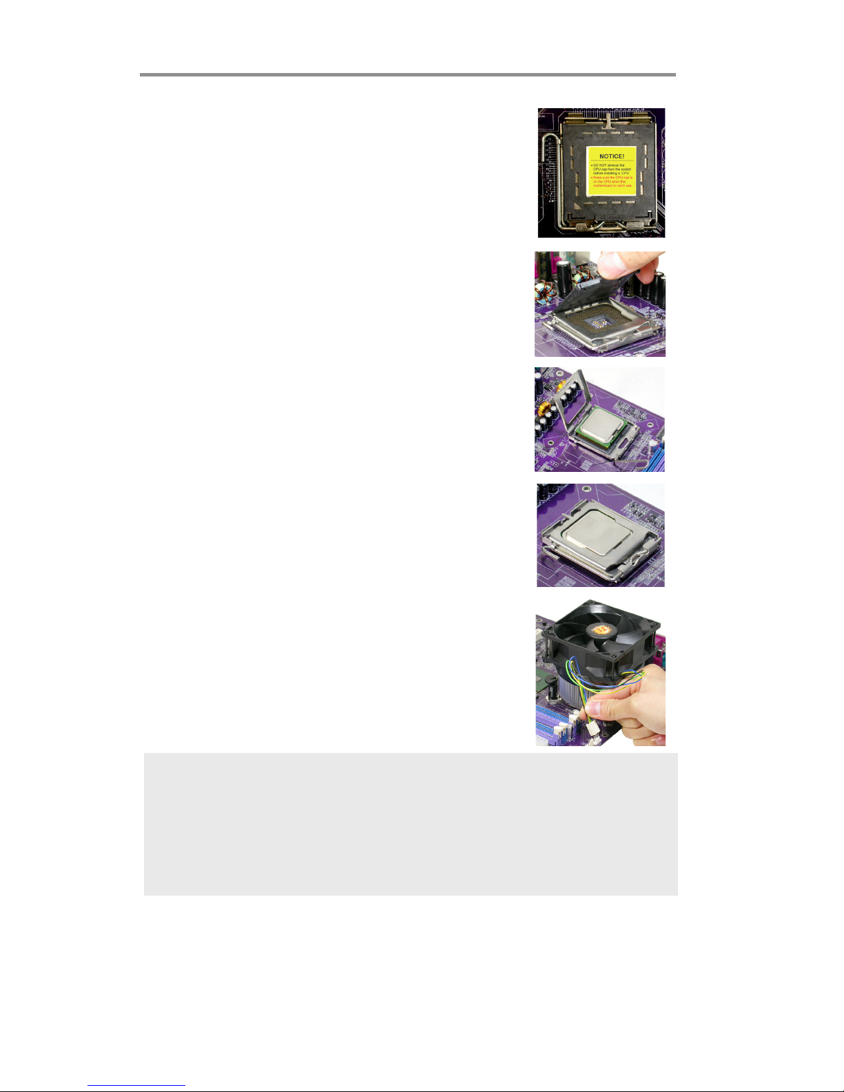
A. Read and follow the instructions shown on the
sticker on the CPU cap.
B. Unload the cap
· Use thumb & forefinger to hold the
lifting tab of the cap.
· Lift the cap up and remove the cap
completely from the socket.
C. Open the load plate
· Use thumb & forefinger to hold the
hook of the lever, pushing down and pulling
aside unlock it.
· Lift up the lever.
· Use thumb to open the load plate. Be
careful not to touch the contacts.
D. Install the CPU on the socket
· Orientate CPU package to the socket.
Make sure you match triangle marker
to pin 1 location.
E. Close the load plate
· Slightly push down the load plate onto the
tongue side, and hook the lever.
· CPU is locked completely.
F. Apply thermal grease on top of the CPU.
G. Fasten the cooling fan supporting base onto
the CPU socket on the motherboard.
H. Make sure the CPU fan is plugged to the
CPU fan connector. Please refer to the CPU
cooling fan user’s manual for more detail
installation procedure.
Note:
1. To achieve better airflow rates and heat dissipation, we suggest that you
use a high quality fan with 3800 rpm at least. CPU fan and heatsink
installation procedures may vary with the type of CPU fan/heatsink sup plied. The form and size of fan/heatsink may also vary.
2. DO NOT remove the CPU cap from the socket before installing a CPU.
3. Return Material Authorization (RMA) requests will be accepted only if the
motherboard comes with the cap on the LGA775 socket.
Installing Memory Modules
This motherboard accommodates two 240-pin DIMM sockets (Dual Inline Memory
Module) for unbuffered DDR2 667/533/400 memory modules (Double Data Rate
SDRAM), and maximum 2 GB installed memory.
Page 14

11
Chapter 2: Motherboard Installation
Memory Module Installation Procedure
These modules can be installed with up to 2 GB system memory. Refer to the
following to install the memory module.
1. Push down the latches on both sides of the DIMM socket.
2. Align the memory module with the socket. There is a notch on the
DIMM socket that you can install the DIMM module in the correct
direction. Match the cutout on the DIMM module with the notch on
the DIMM socket.
3. Install the DIMM module into the socket and press it firmly down
until it is seated correctly. The socket latches are levered upwards
and latch on to the edges of the DIMM.
4. Install any remaining DIMM modules.
Over its predecessor DDR SDRAM, DDR2 SDRAM offers greater bandwidth and
density in a smaller package along with a reduction in power consumption. In
addition, DDR2 SDRAM offers new features and functions that enable a higher
clock rate and data rate operations of 400 MHz, 533 MHz and 667 MHz. DDR2
transfers 64 bits of data twice every clock cycle.
Page 15

12
Motherboard User’s Guide
Please check the table below for the CPU FSB frequency and its corresponding memory
support frequency.
CPU FSB Frequency Memory Support Frequency
1333
DDRII533, DDRII667*
1066
DDRII533, DDRII667
800
DDRII400, DDRII533, DDRII667
533
DDRII400, DDRII533
*When you use a FSB1333-CPU on this motherboard, it will run at DDRII500 if you
adopt a DDRII533 memory module; and it will run at DDRII500 if “DRAM Frequency”
in “Frequency/Voltage Control” of BIOS is selected to “Auto”, while it will run at
DDRII667 when selected to “667MHZ”.
Page 16

13
Chapter 2: Motherboard Installation
Table A: DDR2 (memory module) QVL (Qualified Vendor List)
The following DDR2 667/533 memory modules have been tested and qualified for use
when you use a FSB 1333-CPU on this motherboard.
Type Size Vendor Module Name
Corsair VC256MB533D2 4PB11D9CHM
Elpida Japan E2508AA-T7F-E
Kingmax Hynix HY5PS121621
Nanya NT5TU32M16AG-37B
Ramaxel 5PB42 D9DCD
Ramaxel Elpida D5116AF-5C-E
256 MB
Twinmos Elpida 8D22IB-ED
Aeneon Aeneon AET94F370
Aeneon Aeneon AET93F370
Corsair Samsung K4T51083QB-ZCD5
Corsair VS512MB533D2 64M8CEC
Elpida 04180WB01
Hynix HY5PS12821
Infineon HY818T512800AF37 33346778
Kingston Hynix HYB18T512800AF37
Kingston Hynix HY5PS12821
Kingston Nanya NT5TU64M8AE-37B
Ramaxel 5PB32 D9DCN
Ramaxel Elpida E5108AG-5C-E
Ramaxel 6AD11 D9GCT
Samsung
PC2-4200U-4444-10-B1 K4T51083QF-
ZCD5
Twinmos Samsung 8D22JB-KM
512 MB
Twinmos Elpida E5108AB-5C-E
Apacer Eipida E5108AB-5C-E
Geil A016E2864T2AG8AKT5H120001
Infineon HY818T512800AF37 33344539
Kingmax KKEA88E4AAKG-37
DDR2 533
1 GB
PQI PQI PQB2648D38R0651
256 MB
Infineon HYS64T325001HU-3-A HYB18T256
APOGEE AU51082-667P005
Corsair 64M8CFE PS1000545
Corsair VALUESELECT 32M8CEC
GEIL GL2L64M088BA18W
Infinity 0547W64M8 PC5300
PSC AL6E8E63B-6E1T
Ramxel 5LB31 D9DCL
Samsung K4T51083QC
Sync MAX 04400WB01 R050008A
Twinmos TMM6208G8M30B
512 MB
Transcend JetRam J12Q3AB-6
APOGEE AU51082-667P005
Infineon Aeneon AET93E30RB-0650
PSC AL6E8E63B-6E1T
DDR2 667
1 GB
PQI PQI PQB2648D38R0648
Page 17

14
Motherboard User’s Guide
Jumper Settings
Connecting two pins with a jumper cap is SHORT; removing a jumper cap from
these pins, OPEN.
CLR_CMOS: Clear CMOS Jumper
Use this jumper to clear the contents of the CMOS memory. You may need to clear
the CMOS memory if the settings in the Setup Utility are incorrect and prevent
your motherboard from operating. To clear the CMOS memory, disconnect all the
power cables from the motherboard and then move the jumper cap into the CLEAR
setting for a few seconds.
Note: To avoid the system unstability after clearing CMOS, we recommend
users to enter the main BIOS setting page to “Load Optimal De-faults”
and then “Save Changes and Exit”.
Function Jumper Setting
VCC Short Pins 1-2
5VSB Shor t Pins 2- 3
USBPWR_F/USBPWR_R: USB Power Select Jumper
Use these jumpers to select the voltage for USB port.
Note:1. Make sure the power supply provides enough SB5V voltage before
selecting the SB5V function.
2. It is required that users place the USBPWR_F & USBPWR_R cap onto 2-
3 pin rather than 1-2 pin as default if you want to wake up the computer
by USB/PS2 KB/Mouse.
Fu nc t i o n Jumper Setting
Nor mal
Short Pins 1-2
Clear CMOS Short Pins 2-3
Page 18

15
Chapter 2: Motherboard Installation
Connect the power connector from the power supply to the ATX1 connector on
the motherboard. The ATX12V1 is a +12V connector for CPU Vcore power.
Connect the auxiliary case power connector to the ATX12V1 connector.
Connect the system cooling fan connector to SYS_FAN.
Connect the case speaker cable to SPK1.
Connect the case switches and indicator LEDs to the F_PANEL1 header. Please
refer to the following list of the F_PANEL1 pin assignments.
Install the Motherboard
Install the motherboard in a system chassis (case). The board is a Micro ATX size
motherboard. You can install this motherboard in a Micro ATX case. Make sure
your case has an I/O cover plate matching the ports on this motherboard.
Install the motherboard in a case. Follow the case manufacturer’s instructions to
use the hardware and internal mounting points on the chassis.
Pin Signal Pin Signal
1 HD_ LED_P(+) 2 FP PWR/SLP(+)
3 HD_ LED_N( - ) 4 FP PWR/ SLP(- )
5 RES ET_ SW _ N( - ) 6 PO WER_ SW _P( +)
7 RES ET_ SW _ P( +) 8 PO WER_ S W_ N( - )
9RSVD 10KEY
Page 19

16
Motherboard User’s Guide
Connecting Optional Devices
Refer to the following for information on connecting the motherboard’s optional
devices:
F_AUDIO1: Front Panel Audio Header
This header allows the user to install auxiliary front-oriented microphone and lineout ports for easier access.
F_USB1/F_USB2: Front Panel USB Headers
The motherboard has USB ports installed on the rear edge I/O port array. Additionally, some computer cases have USB ports at the front of the case. If you have this
kind of case, use auxiliary USB headers F_USB1/F_USB2 to connect the frontmounted ports to the motherboard.
Pin Signal Pin Signal
1PORT1L 2GND
3 PO RT1 R 4 PRES ENCE#
5 PORT2R 6 Sense1_return
7 S ENS E_S END 8 KEY
9 PORT2L 10 Sense2_return
Page 20

17
Chapter 2: Motherboard Installation
1 Locate the F_USB1/F_USB2 headers on the motherboard.
2 Plug the bracket cable onto the F_USB1/F_USB2 headers.
3 Remove a slot cover from one of the expansion slots on the system
chassis. Install an extension bracket in the opening. Secure the
extension bracket to the chassis with a screw.
Pin Signal Pin Signal
1 USBPWR 2 USBPWR
3 USB_FP_P0(-) 4 USB_FP_P1(-)
5 USB_FP_P0(+) 6 USB_FP_P1(+)
7GND 8GND
9 KEY 10 USB_FP_OC0
Here is a list of headers F_USB1/F_USB2 pin assignments.
SPDIFO1: SPDIF Out Header
This is an optional header that provides an S/PDIF (Sony/Philips Digital Interface)
output to digital multimedia device through optical fiber or coxial connector.
Pin Signal
1SPDIFOUT
2+5V
3Key
4GND
Page 21

18
Motherboard User’s Guide
Install Other Devices
Install and connect any other devices in the system following the steps below.
Floppy Disk Drive
The motherboard ships with a floppy disk drive cable that can support one or two
drives. Drives can be 3.5" or 5.25" wide, with capacities of 360K, 720K, 1.2MB,
1.44MB, or 2.88MB.
Install your drives and connect power from the system power supply. Use the
cable provided to connect the drives to the floppy disk drive connector FDD.
IDE Devices
IDE devices include hard disk drives, high-density diskette drives, and CD-ROM
or DVD-ROM drives, among others.
The motherboard ships with an IDE cable that can support one or two IDE devices.
IDE1 can support up to 2 IDE devices, data transporting in ATA-33/66/100 mode.
Serial ATA Devices
The Serial ATA (Advanced Technology Attachment) is the standard interface for
the IDE hard drives, which is designed to overcome the design limitations while
enabling the storage interface to scale with the growing media rate demands of PC
platforms. It provides you a faster transfer rate of 3.0 Gb/s. If you have installed a
Serial ATA hard drive, you can connect the Serial ATA cables to the Serial ATA hard
drive or the connecter on the motherboard.
Page 22

19
Chapter 2: Motherboard Installation
Analog Audio Input Header
If you have installed a CD-ROM drive or DVD-ROM drive, you can connect the
drive audio cable to the onboard sound system.
When you first start up your system, the BIOS should automatically detect your
CD-ROM/DVD drive. If it doesn’t, enter the Setup Utility and configure the CDROM/DVD drive that you have installed. On the motherboard, locate the 4-pin
header CD_IN1.
Pin Signal
1 CD_L
2 GND
3 GND
4 CD_R
On the motherboard, locate the Serial ATA connectors SATA1-4, which support
new Serial ATA devices for the highest data transfer rates, simpler disk drive cabling
and easier PC assembly.
It eliminates limitations of the current Parallel ATA interface, but maintains register
compatibility and software compatibility with Parallel ATA.
1
Page 23

20
Motherboard User’s Guide
1. Before installing an add-on card, check the documentation for the card
carefully. If the card is not Plug and Play, you may have to manually configure the card before installation.
2. FSB1333-CPU will operate in overclocking mode. Under this situation,
PCIE frequency will also be overclocked from 100MHz to 125MHz.
Note:
Expansion Slots
This motherboard has one PCIEX16 slot and two 32-bit PCI slots.
This motherboard is equipped with two standard PCI slots. PCI
stands for Peripheral Component Interconnect and is a bus standard
for expansion cards, which for the most part, is a supplement of the
older ISA bus standard. The PCI slots on this board are PCI v2.3
compliant.
PCI 1~2
Slots
PCIEX16
Slot
The PCIEX16 is used to install an external PCI Express graphics card
that is fully compliant to the PCI Express Base Specification revision
1.0a.
Page 24

21
Chapter 2: Motherboard Installation
Follow these instructions to install an add-on card:
1 Remove a blanking plate from the system case corresponding to the slot
you are going to use.
2 Install the edge connector of the add-on card into the expansion slot.
Ensure that the edge connector is correctly seated in the slot.
3 Secure the metal bracket of the card to the system case with a screw.
For some add-on cards, for example graphics adapters and network
adapters, you have to install drivers and software before you can begin
using the add-on card.
Note:
Page 25

22
Motherboard User’s Guide
Chapter 3 BIOS Setup Utility
Introduction
The BIOS Setup Utility records settings and information of your computer, such
as date and time, the type of hardware installed, and various configuration settings.
Your computer applies the information to initialize all the components when booting up and basic functions of coordination between system components.
If the Setup Utility configuration is incorrect, it may cause the system to malfunction. It can even stop your computer booting properly. If it happens, you can use
the clear CMOS jumper to clear the CMOS memory which has stored the configuration information; or you can hold down the Page Up key while rebooting your
computer. Holding down the Page Up key also clears the setup information.
You can run the setup utility and manually change the configuration. You might
need to do this to configure some hardware installed in or connected to the
motherboard, such as the CPU, system memory, disk drives, etc.
Running the Setup Utility
Every time you start your computer, a message appears on the screen before the
operating system loading that prompts you to “Hit <DEL>if you want to run
SETUP”. Whenever you see this message, press the Delete key, and the Main
menu page of the Setup Utility appears on your monitor. If you manually clear
CMOS, you need to press the F1 key that enters the Main menu page of the Setup
Utility.
CMOS SETUP UTILITY – Copyright (C) 1985-2005, American Megatrends, Inc.
V02.58 (C)Copyright 1985-2004, American Megatrends, Inc.
Standard CMOS Setup
Advanced Setup
Advanced Chipset Setup
Integrated Peripherals
Power Management Setup
PCI/PnP Setup
PC Health Status
Frequency/Voltage Control
Load Default Settings
Supervisor Password
User Password
Save & Exit Setup
Exit Without Saving
: Move
F10: Save and Exit
Enter : Select
+/-/: Value
F9: Optimized Defaults ESC: Exit
F1: General Help
Page 26

23
Chapter 3: BIOS Setup Utility
You can use cursor arrow keys to highlight anyone of options on the main menu
page. Press Enter to select the highlighted option. Press the Escape key to leave
the setup utility. Press +/-/ to modify the selected field’s values.
Some options on the main menu page lead to tables of items with installed values
that you can use cursor arrow keys to highlight one item, and press
++
++
+ and
--
--
- keys to
cycle through alternative values of that item. The other options on the main menu
page lead to dialog boxes requiring your answer OK or Cancel by selecting [OK] or
[Cancel].
If you have already changed the setup utility, press F10 to save those changes and
exit the utility. Press F1 to display a screen describing all key functions. Press F8
to load fail-safe defaults. Press F9 to install the setup utility with a set of default
values.
Standard CMOS Setup Page
This page displays a table of items defining basic information about your system.
Processor
The item is automatically detected by the system at start up time. The Processor
item shows the processor type and speed installed in your computer. This is
display-only field. You cannot make changes to this field.
System Memory
The item is automatically detected by the system at start up time. This is displayonly field. You cannot make changes to this field.
Time and Date
The Date and Time items show the current date and time on the computer. If
you are running a Windows OS, these items are automatically updated whenever
you make changes to the Windows Date and Time Properties utility.
CMOS Setup Utility -- Copyright (C) 1985-2005, American Megatrends, Inc.
Standard CMOS Setup
mnlk
System Date Mon 01/01/2007
f
Primary IDE Master Not Detected
Primary IDE Slave Not Detected
Secondary IDE Master Not Detected
Secondary IDE Slave Not Detected
Help Item
f
f
System Time 00:12:59
Use [ENTER], [TAB] or
[SHIFT-TAB] to select a
field.
Use [+] or [-] to
configure system Date.
Third IDE Master Not Detected
Third IDE Slave Not Detected
f
f
PCI IDE Bus Master Enabled
Floppy A Not Detected
: Move
F10: Save and Exit
Enter : Select
+/-/: Value
F9: Optimized Defaults ESC: Exit
F1: General Help
f
Page 27

24
Motherboard User’s Guide
IDE Devices
f
Your computer has one IDE channel which can be installed with one or two devices
(Master and Slave). In addition, this motherboard supports two SATA channels and
each channel allows one SATA device to be installed. Use these items to configure each
device on the IDE channel.
Select the type
of device connected
to the system.
LBA/Large Mode (Auto)
Use this item to set the LAB/Large mode to enhance hard disk performance by
optimizing the area the hard disk is visited each time.
Block (Multi-Sector Transfer) (Auto)
If the feature is enabled, it will enhance hard disk performance by reading or writing
more data during each transfer.
Type (Auto)
Use this item to configure the type of the IDE device that you specify. If the feature
is enabled, it will enhance hard disk performance by reading or writing more data during
each transfer.
CMOS SETUP UTILITY – Copyright (C) 1985-2005, American Megatrends, Inc.
Primary IDE Master
Primary IDE Master
Type Auto
LBA/Large Mode Auto
Block (Multi-Sector Transfer) Auto
PIO Mode Auto
DMA Mode Auto
S.M.A.R.T Auto
32Bit Data Transfer Enabled
Help Item
Device : Not Detected
F10: Save and Exit
mnlk
: Move Enter : Select
+/-/: Value
F9: Optimized Defaults ESC: Exit
F1: General Help
32Bit Data Transfer (Enabled)
Use this item to set the onboard SATA-IDE channel to be disabled, IDE, or RAID.
S.M.A.R.T. (Auto)
The S.M.A.R.T. (Self-Monitoring, Analysis and Reporting Technology) system is a
diagnostics technology that monitors and predicts device performance. S.M.A.R.T.
software resides on both the disk drive and the host computer.
DMA Mode (Auto)
DMA capability allows user to improve the transfer-speed and data-integrity for compatible IDE devices.
PIO Mode (Auto)
Use this item to set the PIO mode to enhance hard disk performance by optimizing the
hard disk timing.
Page 28

25
Chapter 3: BIOS Setup Utility
Press <Esc> to return to the Standard CMOS Setup page.
F1: General Help
Advanced Setup
This page sets up more advanced information about your system. Handle this page with
caution. Any changes can affect the operation of your computer.
Boot Up Numlock Status (On)
This item defines if the keyboard Num Lock key is active when your system is started.
CPU TM function (Enabled)
For some specific brands of CPU, you can use this item to control the CPU frequency
and voltage according to its temperature.
Max CPUID Value Limit (Disabled)
Use this item to enable or disable the Max CPU ID value limit. When supports Prescott
and LGA775 CPUs, enables this to prevent the system from “rebooting” when trying
to install Windows NT 4.0.
Execute Disable Bit (Disabled)
This item is a security feature that helps you protect your CPU and operating system
against malicious software executing code. This item is available when CPU supports
the feature.
Intel (R) SpeedStep (tm) tech. (Disabled)
This item allows users to enable or disable the EIST (Enhanced Intel Speedstep Technology) function. This item shows only if the CPU supports EIST.
Enhanced Halt (C1E) (Enabled)
This item enables or disables enhanced halt.
Quick Power on Self Test (Enabled)
Enable this item to shorten the power on testing (POST) and have your system start
up faster. You might like to enable this item after you are confident that your system
hardware is operating smoothly.
CMOS Setup Utility - Copyright (C) 1985-2005, American Megatrends, Inc.
Advanced Setup
CPU TM function Enabled
Max CPUID Value Limit Disabled
Execute Disable Bit Disabled
Intel(R) SpeedStep(tm) tech. Disabled
Enhanced Halt (C1E) Enabled
Quick Power on Self Test Enabled
Boot up NumLock Status On
APIC Mode Enabled
Boot Other Device Enabled
Security Check System
For the processor its
CPUID belows 0F41h.
TM2 only can be enable
under below setting.
1.Freq. >=3.6GHz FSB800
2.Freq. >=2.8GHz FSB533
Help Item
mnlk
: Move
F10: Save and Exit
Enter : Select
+/-/: Value
F9: Optimized Defaults ESC: Exit
Page 29

26
Motherboard User’s Guide
APIC Mode (Enabled)
This item allows you to enable or disable the APCI (Advanced Programmable Interrupt
Controller) mode. APIC provides symmetric multi-processing (SMP) for systems,
allowing support for up to 60 processors.
Boot Other Device (Enabled)
When enabled, the system searches all other possible locations for an operating system
if it fails to find one in the devices specified under the First, Second and Third boot
devices.
Security Check (System)
This item is set to enable or disable the security check.
Configure DRAM Timing (By SPD)
When this item is set to enable, the DDR timing is configured using SPD. SPD (Serial
Presence Detect) is located on the memory modules, BIOS reads information coded in
SPD during system boot up.
DVMT Mode Select (DVMT Mode)
This item allows you to select the DVMT operating mode.
DVMT/Fixed Memory (128MB)
When set to Fixed Mode, the graphics driver will reserve a fixed portion of the system
memory as graphics memory. When set to DVMT Mode, the graphics chip will dynamically allocate system memory as graphics memory, according to system and
graphics requirements.
Press <Esc> to return to the main menu setting page.
Advanced Chipset Setup
This page sets up more advanced information about your system. Handle this page
with caution. Any changes can affect the operation of your computer.
CMOS Setup Utility - Copyright (C) 1985-2005, American Megatrends, Inc.
Advanced Chipset Setup
Configure DRAM Timing By SPD
DVMT Mode Select DVMT Mode
DVMT/Fixed Memory 128MB
Share Memory Size Enabled, 8MB
Help Item
Options
Manual
By SPD
mnlk
: Move Enter : Select
+/-/: Value
F9: Optimized Defaults ESC: Exit
F1: General Help
F10: Save and Exit
Page 30

27
Chapter 3: BIOS Setup Utility
Share Memory Size (Enabled, 8MB)
This item lets you allocate a portion of the main memory for the onboard VGA display
application.
Press <Esc> to return to the main menu setting page.
Integrated Peripherals
This page sets up some parameters for peripheral devices connected to the system.
CMOS Setup Utility - Copyright (C) 1985-2005, American Megatrends, Inc.
Integrated Peripherals
Onboard IDE Controller Enabled
Onboard SATA Controller Enabled
USB Functions Enabled
Legacy USB Support Enabled
Audio Controller Enabled
Onboard LAN Function Enabled
Onboard LAN Boot ROM Disabled
Serial Port1 Address 3F8&IRQ4
Disable / Enable the
integrated IDE
Controller.
Help Item
mnlk
: Move Enter : Select
+/-/: Value
F9: Optimized Defaults ESC: Exit
F1: General Help
F10: Save and Exit
Onboard IDE Controller (Enabled)
Use this item to enable or disable the onboard IDE interface.
Onboard SATA Controller (Enabled)
Use this item to enable or disable the onboard SATA controller.
USB Functions (Enabled)
Use this item to enable or disable the USB function.
Parallel Port Address 378
Parallel Port Mode ECP
ECP Mode DMA Channel DMA3
Parallel Port IRQ IRQ7
Legacy USB Support (Enabled)
Use this item to enable or disable support for legacy USB devices. Setting to Auto
allows the system to detect the presence of USB device at startup. If detected, the USB
controller legacy mode is enabled. If no USB device is detected, the legacy USB support
is disabled.
Audio Controller (Enabled)
Use this item to enable or disable the onboard audio controller.
OnBoard LAN Function (Enabled)
Use this item to enable or disable the onboard LAN function.
OnBoard LAN Boot ROM (Disabled)
Use this item to enable or disable the booting from the onboard LAN or a network addin card with a remote boot ROM installed.
Page 31

28
Motherboard User’s Guide
Parallel Port Address (378)
Use this item to enable or disable the onboard Parallel port, and to assign a port address.
Parallel Port Mode (ECP)
Use this item to select the parallel port mode. You can selet Normal (Standard Parallel
Port), ECP (Extended Capabilities Port), EPP (Enhanced Parallel Port), or BPP (BiDirectional Parallel Port).
ECP Mode DMA Channel (DMA3)
Use this item to assign the DMA Channel under ECP Mode function.
Parallel Port IRQ (IRQ7)
Use this item to assign IRQ to the parallel port.
Serial Port1 Address (3F8&IRQ4)
Use this item to enable or disable the onboard COM1/2 serial port, and to assign a port
address.
Power Management Setup
This page sets up some parameters for system power management operation.
Select the ACPI
state used for
System Suspend.
Help Item
CMOS Setup Utility - Copyright (C) 1985-2005, American Megatrends, Inc.
Power Management Setup
*ACPI Suspend Mode S3 (STR)
Soft-off by PWR-BTTN Delay 4 Sec
PWRON After PWR-Fail Power Off
Resume On LAN Disabled
Wake-Up by PME Enabled
Power On by Ring Disabled
USB KB Wakeup From S3 Disabled
PS2 Keyboard Wakeup Disabled
PS2 Mouse Wakeup Disabled
Resume on RTC Alarm Disabled
mnlk
: Move Enter : Select
+/-/: Value
F9: Optimized Defaults ESC: Exit
F1: General Help
F10: Save and Exit
*ACPI Suspend Mode (S3(STR))
Use this item to define how your system suspends. In the default, S3, the suspend mode
is a suspend to RAM, i.e, the system shuts down with the exception of a refresh current
to the system memory.This item will not show when the FSB reaches 1333MHz.
Soft-Off By PWR-BTTN (Delay 4 Sec)
Under ACPI (Advanced Configuration and Power management Interface) you can
create a software power down. In a software power down, the system can be resumed by
Wake Up Alarms. This item lets you install a software power down that is controlled by
the power button on your system. If the item is set to Instant-Off, then the power
button causes a software power down. If the item is set to Delay 4 Sec, then you have
to hold the power button down for four seconds to cause a software power down.
Press <Esc> to return to the main menu setting page.
Page 32

29
Chapter 3: BIOS Setup Utility
PWRON After PWR-Fail (Power Off)
This item enables your computer to automatically restart or return to its operating
status.
Resume On LAN (Disabled)
This item allows users to enable or disable LAN activity to wake up the system from
a power saving mode.
Wake-Up by PME (Enabled)
The system can be turned off with a software command. If you enable this item, the
system can automatically resume if there is an incoming call on the PCI Modem or
PCI LAN card. You must use an ATX power supply in order to use this feature. Use this
item to do wake-up action if inserting the PCI card.
Power On by Ring (Disabled)
The system can be turned off with a software command. If you enable this item, the
system can automatically resume if there is an incoming call on the Modem. You must
use an ATX power supply in order to use this feature.
USB KB Wakeup From S3 (Disabled)
This item allows you to enable/disable the USB device wakeup function from S3/S4
mode.
PS2 Keyboard Wakeup (Disabled)
This item enable or disable you to allow keyboard activity to awaken the system from
power saving mode.
PS2 Mouse Wakeup (Disabled)
This item enable or disable you to allow mouse activity to awaken the system from
power saving mode.
Resume on RTC Alarm (Disabled)
The system can be turned off with a software command. If you enable this item, the
system can automatically resume at a fixed time based on the system’s RTC (realtime
clock). Use the items below this one to set the date and time of the wake-up alarm. You
must use an ATX power supply in order to use this feature.
Press <Esc> to return to the main menu setting page.
PCI / PnP Setup
This page sets up some parameters for devices installed on the PCI bus and those
utilizing the system plug and play capability.
Help ItemInit Display First PCI Card
Allocate IRQ to PCI VGA Yes
CMOS Setup Utility - Copyright (C) 1985-2005, American Megatrends, Inc.
PCI / PnP Setup
Select which graphics
controller to use as
the primary boot
device.
mnlk
: Move Enter : Select
+/-/: Value
F9: Optimized Defaults ESC: Exit
F1: General Help
F10: Save and Exit
Page 33

30
Motherboard User’s Guide
Init Display First (PCI Card)
Use this item to select which graphics controller to use as the primary boot devices.
Allocate IRQ to PCI VGA (Yes)
If this item is enabled, an IRQ will be assigned to the PCI VGA graphics system. You set
this value to No to free up an IRQ.
PC Health Status
On motherboards support hardware monitoring, this item lets you monitor the parameters for critical voltages, temperatures and fan speeds.
Press <Esc> to return to the main menu setting page.
Hardware Health Event Monitoring
Smart Fan Function Press Enter
Shutdown Temperature Disabled
CPU Temperature 39°C/102°F
CPU Fan Speed 4272 RPM
CPU VCore 1.280 V
VDIMM 1.840 V
Help Item
CMOS Setup Utility - Copyright (C) 1985-2005, American Megatrends, Inc.
PC Health Status
f
mnlk
: Move Enter : Select
+/-/: Value
F9: Optimized Defaults ESC: Exit
F1: General Help
F10: Save and Exit
Smart Fan Function
f
Scroll to this item and press <Enter> to view the following screen:
CMOS Setup Utility - Copyright (C) 1985-2005, American Megatrends, Inc.
Smart Fan Function
SMART Fan Control Disabled
Fan configuration
mode setting
Help Item
mnlk
: Move Enter : Select
+/-/: Value
F9: Optimized Defaults ESC: Exit
F1: General Help
F10: Save and Exit
Page 34

31
Chapter 3: BIOS Setup Utility
SMART Fan Control (Disabled)
This item allows you to enable/disable the control of the system fan speed by
changing the fan voltage.
Press <Esc> to return to the PC Health Status page.
Shutdown Temperature (Disabled)
Enable you to set the maximum temperature the system can reach before powering
down.
System Component Characteristics
These items display the monitoring of the overall inboard hardware health events,
such as System & CPU temperature, CPU & DIMM voltage, CPU & system fan
speed,...etc.
• CPU Temperature
• CPU Fan Speed
• CPU VCore
• VDIMM
Press <Esc> to return to the main menu setting page.
CMOS Setup Utility - Copyright (C) 1985-2005, American Megatrends, Inc.
Frequency/Voltage Control
Help item
Manufacturer : Intel
CPU Frequency Setting 266MHz
DRAM Frequency Auto
Auto Detect DIMM/PCI Clk Enabled
Spread Spectrum Disabled
CPU Frequency Auto
Options
Auto
400 MHz
533 MHz
667 MHz
mnlk
: Move Enter : Select
+/-/: Value
F9: Optimized Defaults ESC: Exit
F1: General Help
F10: Save and Exit
Frequency/Voltage Control
This page enables you to set the clock speed and system bus for your system. The clock
speed and system bus are determined by the kind of processor you have installed in your
system.
Manufacturer (Intel)
This item displays the information of current manufacturer of the CPU installed in
your computer.
Page 35

32
Motherboard User’s Guide
CPU Frequency Setting (266MHz)
This item allows you to set CPU frequency. And the CPU frequency will be 333MHz
when the FSB reaches 1333MHz.
DRAM Frequency (Auto)
This item shows the frequency of the DRAM in your computer. When it is FSB
1333MHz CPU, the select options will be Auto, 533MHz, and 667MHz, and when it
is not FSB 1333MHz CPU, the select options will be Auto, 400MHz, 533MHz and
667MHz.
Auto Detect DIMM/PCI Clk (Enabled)
When this item is enabled, BIOS will disable the clock signal of free DIMM/PCI slots.
Spread Spectrum (Disabled)
If you enable spread spectrum, it can significantly reduce the EMI (Electro-Magnetic
Interference) generated by the system.
CPU Frequency (Auto)
Use this option to adjust CPU frequency. And this item shows only when the FSB
reaches 1333 MHz.
Supervisor Password
This page helps you install or change a password.
Load Optimal Defaults
This option opens a dialog box that lets you install optimized defaults for all appropriate items in the Setup Utility. Press <Y> and then <Enter> to install the defaults. Press
<N> and then <Enter> to not install the defaults. The optimized defaults place demands on the system that may be greater than the performance level of the components, such as the CPU and the memory. You can cause fatal errors or instability if you
install the optimized defaults when your hardware does not support them. If you only
want to install setup defaults for a specific option, select and display that option, and
then press <F7>.
CMOS Setup Utility - Copyright (C) 1985-2005, American Megatrends, Inc.
Supervisor Password
Install or Change the
password.
Help item
Security Settings
Supervisor Password : Not Installed
Change Supervisor Password Press Enter
mnlk
: Move Enter : Select
+/-/: Value
F9: Optimized Defaults ESC: Exit
F1: General Help
F10: Save and Exit
Press <Esc> to return to the main menu setting page.
Page 36

33
Chapter 3: BIOS Setup Utility
Supervisor Password (Not Installed)
This item indicates whether a supervisor password has been set. If the password has
been installed, Installed displays. If not, Not Installed displays.
Change Supervisor Password (Press Enter)
You can select this option and press <Enter> to access the sub menu. You can use the
sub menu to change the supervisor password.
Press <Esc> to return to the main menu setting page.
User Password
This page helps you install or change a password.
User Password (Not Installed)
This item indicates whether a user password has been set. If the password has been
installed, Installed displays. If not, Not Installed displays.
Change User Password (Press Enter)
You can select this option and press <Enter> to access the sub menu. You can use the
sub menu to change the supervisor password.
Press <Esc> to return to the main menu setting page.
Install or Change the
password.
Help item
CMOS Setup Utility - Copyright (C) 1985-2005, American Megatrends, Inc.
User Password
Security Settings
User Password : Not Installed
Change User Password Press Enter
mnlk
: Move Enter : Select
+/-/: Value
F9: Optimized Defaults ESC: Exit
F1: General Help
F10: Save and Exit
Page 37

34
Motherboard User’s Guide
Save & Exit Setup
Highlight this item and press <Enter> to save the changes that you have made in the
Setup Utility and exit the Setup Utility. When the Save and Exit dialog box appears,
select [OK] to save and exit, or select [Cancel] to return to the main menu.
Exit Without Saving
Highlight this item and press <Enter> to discard any changes that you have made in the
Setup Utility and exit the Setup Utility. When the Exit Without Saving dialog box
appears, select [OK] to discard changes and exit, or select [Cancel] to return to the
main menu.
Note: If you have made settings that you do not want to save, use the “Discard
Changes and Exit” item and press <OK> to discard any changes you have made.
Page 38

35
Chapter 4: Software & Applications
Chapter 4 Software & Applications
Introduction
This chapter describes the contents of the support CD-ROM that comes with the
motherboard package.
The support CD-ROM contains all useful software, necessary drivers and utility
programs to properly run our products. More program information is available in
a README file, located in the same directory as the software.
To run the support CD, simply insert the CD into your CD-ROM drive. An Auto
Setup screen automatically pops out, and then you can go on the auto-installing or
manual installation depending on your operating system.
If your operating system is Windows 2000/XP, it will automatically install all the
drivers and utilities for your motherboard; if Windows NT or manual installation,
please follow the instructions described as the Installing under Windows NT or
Manual Installation section.
Installing Support Software
1 Insert the support CD-ROM disc in the CD-ROM drive.
2 When you insert the CD-ROM disc in the system CD-ROM drive, the
CD automatically displays an Auto Setup screen.
3 The screen displays three buttons of Setup, Browse CD and Exit on
the right side, and three others Setup, Application and ReadMe at the
bottom. Please see the following illustration.
The Setup button runs the software auto-installing program as explained in next
section.
Page 39

36
Motherboard User’s Guide
The Browse CD button is a standard Windows command that you can check the
contents of the disc with the Windows 98 file browsing interface.
The Exit button closes the Auto Setup window. To run the program again, reinsert
the CD-ROM disc in the drive; or click the CD-ROM driver from the Windows
Explorer, and click the Setup icon.
The Application button brings up a software menu. It shows the bundled software
that this mainboard supports.
The ReadMe brings you to the Install Path where you can find out path names of
software driver.
Auto-Installing under Windows 2000/XP
If you are under Windows 2000/XP, please click the Setup button to run the
software auto-installing program while the Auto Setup screen pops out after inserting the support CD-ROM:
1 The installation program loads and displays the following screen. Click
the Next button.
2 Select the items that you want to setup by clicking on it (the default
options are recommended). Click the Next button to proceed.
Page 40

37
Chapter 4: Software & Applications
3 The support software will automatically install.
Once any of the installation procedures start, software is automatically installed in
sequence. You need to follow the onscreen instructions, confirm commands and
allow the computer to restart as few times as needed to complete installing whatever software you selected. When the process is finished, all the support software
will be installed and start working.
Installing under Windows NT or Manual Installation
If you are under Windows NT, the auto-installing program doesn’t work out; or
you have to do the manual installation, please follow this procedure while the Auto
Setup screen pops out after inserting the support CD-ROM:
1 Click the ReadMe to bring up a screen, and then click the Install Path at
the bottom of the screen.
2 Find out your mainboard model name and click on it to obtain its correct
driver directory.
3 Install each software in accordance with the corresponding driver path.
Bundled Software Installation
All bundled software available on the CD-ROM is for users’ convenience. You can
install bundled software as follows:
1 Click the Application button while the Auto Setup screen pops out
after inserting the support CD-ROM.
2 A software menu appears. Click the software you want to install.
3 Follow onscreen instructions to install the software program step by
step until finished.
Page 41

38
Motherboard User’s Guide
Hyper-Threading CPU
While you are in Windows Task Manager, please push down ctrl+Alt Del keys. A
dual CPU appears in the CPU Usage History&Device Manager under WinXP.
Note: Hyper-Threading Function only works under WINXP Operating System;
therefore, disable it under other Operating System.
 Loading...