

Page 1

iii
Page 2

iv
Page 3

Preface
Copyright
This publication, including all photographs, illustrations and software, is protected under
international copyright laws, with all rights reserved. Neither this manual, nor any of the
material contained herein, may be reproduced without written consent of the author.
Version 1.0b
Disclaimer
The information in this document is subject to change without notice. The manufacturer
makes no representations or warranties with respect to the contents hereof and specifically
disclaims any implied warranties of merchantability or fitness for any particular purpose.
The manufacturer reserves the right to revise this publication and to make changes from
time to time in the content hereof without obligation of the manufacturer to notify any
person of such revision or changes.
Trademark Recognition
Microsoft, MS-DOS and Windows are registered trademarks of Microsoft Corp.
nVIDIA is a registered trademark of nVIDIA Corporation
Other product names used in this manual are the properties of their respective owners and
are acknowledged.
Federal Communications Commission (FCC)
This equipment has been tested and found to comply with the limits for a Class B digital
device, pursuant to Part 15 of the FCC Rules. These limits are designed to provide reasonable protection against harmful interference in a residential installation. This equipment
generates, uses, and can radiate radio frequency energy and, if not installed and used in
accordance with the instructions, may cause harmful interference to radio communications.
However, there is no guarantee that interference will not occur in a particular installation.
If this equipment does cause harmful interference to radio or television reception, which
can be determined by turning the equipment off and on, the user is encouraged to try to
correct the interference by one or more of the following measures:
• Reorient or relocate the receiving antenna.
• Increase the separation between the equipment and the receiver.
• Connect the equipment onto an outlet on a circuit different from that to which
the receiver is connected.
• Consult the dealer or an experienced radio/TV technician for help.
Shielded interconnect cables and a shielded AC power cable must be employed with this
equipment to ensure compliance with the pertinent RF emission limits governing this
device. Changes or modifications not expressly approved by the system’s manufacturer
could void the user’s authority to operate the equipment.
Preface
Page 4

ii
Declaration of Conformity
This device complies with part 15 of the FCC rules. Operation is subject to the following
conditions:
• This device may not cause harmful interference, and
• This device must accept any interference received, including interference
that may cause undesired operation.
Canadian Department of Communications
This class B digital apparatus meets all requirements of the Canadian Interference-causing
Equipment Regulations.
Cet appareil numérique de la classe B respecte toutes les exigences du Réglement sur le
matériel brouilieur du Canada.
About the Manual
The manual consists of the following:
Chapter 1
Introducing the Motherboard
Chapter 2
Installing the Motherboard
Chapter 3
Using BIOS
Chapter 4
Using the Motherboard Software
Describes features of the motherboard.
Go to
Describes installation of motherboard
components.
Go to
Provides information on using the BIOS
Setup Utility.
Go to
Describes the motherboard software
Go to
H
H
H
H
page 1
page 7
page 23
page 43
Preface
Page 5

TT
ABLE OF CONTENTSABLE OF CONTENTS
T
ABLE OF CONTENTS
TT
ABLE OF CONTENTSABLE OF CONTENTS
Preface i
iii
Chapter 1
Introducing the Motherboard 1
Introduction................................................................................................1
Features.......................................................................................................2
Motherboard Components.......................................................................4
1
Chapter 2
Installing the Motherboard 7
Safety Precautions......................................................................................7
Choosing a Computer Case.......................................................................7
Installing the Motherboard in a Case......................................................7
Checking Jumper Settings.........................................................................8
Setting Jumpers..............................................................................8
Checking Jumper Settings..............................................................9
Jumper Settings..............................................................................9
Connecting Case Components...............................................................10
Front Panel Header.....................................................................12
Installing Hardware...................................................................................12
Installing the Processor...............................................................12
Installing Memory Modules.........................................................14
Installing a Hard Disk Drive/CD-ROM/SATA Hard Drive........16
Installing a Floppy Diskette Drive...............................................18
Installing Add-on Cards..............................................................18
Connecting Optional Devices......................................................20
Connecting I/O Devices..........................................................................22
7 7
7
7 7
Chapter 3
Using BIOS 23
About the Setup Utility............................................................................23
The Standard Configuration........................................................23
Entering the Setup Utility..............................................................23
Updating the BIOS.......................................................................25
Using BIOS................................................................................................25
Standard CMOS Features...........................................................26
Advanced BIOS Features.............................................................28
Advanced Chipset Features.........................................................30
23 23
23
23 23
Page 6

iv
Integrated Peripherals.................................................................32
Power Management Setup...........................................................36
PNP/PCI Configurations.............................................................38
PC Health Status..........................................................................39
Load Performance.......................................................................40
Load Optimized Defaults.............................................................40
Set Supervisor/User Password....................................................40
Save & Exit Setup Option.............................................................41
Exit Without Saving......................................................................41
Chapter 4
43 43
43
43 43
Using the Motherboard Software 43
About the Software CD-ROM................................................................43
Auto-installing under Windows 2000/XP.............................................43
Running Setup..............................................................................44
Manual Installation..................................................................................46
Utility Software Reference.......................................................................46
Multi-Language T ranslation
Page 7

Chapter 1
Introducing the Motherboard
Introduction
Thank you for choosing the NFORCE4-A939 motherboard. This motherboard is a high
performance, enhanced function motherboard that supports Socket 939 AMD Sempron/
Athlon 64/Athlon 64 FX/Athlon 64 X2 CPUs for high-end business or personal desktop
markets.
The NFORCE4-A939 motherboard is based on NVIDIA®CrushK8-04 (CK8-04) media and
communications processor (MCP) for best desktop platform solution. CrushK8-04 is a
single-chip, highly integrated, high performance HyperTransport peripheral controller,
unmatched by any other single chip-device controller. This motherboard supports up to
4GB of system memory with PC3200/2700/2100/1600 DDR DIMMs, high resolution graphics via an PCI Express x16 slot, Giga LAN, USB 2.0, 6-channel audio, and Digital S/PDIF out.
There is an advanced full set of I/O ports in the rear panel, including PS/2 mouse and
keyboard connectors, COM1, LPT1, four USB ports, one optional LAN port, one optional
coaxial SPDIF out, one optional optical SPDIF out and audio jacks for microphone, line-in,
and line-out. This motherboard is designed in an ATX form factor using a four-layer printed
circuit board and measures 305 mm x 244 mm.
1
Introducing the Motherboard
Page 8

2
Feature
Processor
This motherboard uses a 939-pin socket that carries the following features:
• Accommodates AMD Sempron/Athlon 64/Athlon 64 FX/Athlon 64 X2 processors
• Supports up to 2000 MT/s HyperTransportTM (HT) interface Speeds
HyperTransportTM Technology is a point-to-point link between two devices, it enables
integrated circuits to exchange information at much higher speeds than currently available interconnect technologies.
Chipset
The NVIDIA® CrushK8-04 (CK8-04) is a single-chip with proven reliability and performance.
• HyperTransport x16 up and down links at up to 1.0 GHz to the AMD Sempron/
Athlon 64/Athlon 64 FX/Athlon 64 X2 processors
• PCI 2.3 interface, supporting up to five PCI slots
• Two separate SATA controllers with integrated PHYs, each supporting two
drives in master mode
• IEEE 802.3 NVIDIA MAC for 1000BASE-T/100BASE-T/10BASE-T
• USB 2.0 EHCI and USB 1.1 OHCI, supporting up to ten ports
• Fast ATA-133 IDE controller
• AC’97 2.3 interface, supporting S/PDIF pass-through function and standard,
enhanced audio functionality
• Supports Gigabit/Fast Ethernet/Ethernet
Memory
• Dual-channel DDR memory architecture
• 4 x 184-pin, DDR SDRAM DIMM sockets support up to 4 GB
• Support DDR400/333/266/200 unbuffered DDR SDRAM
AC’97 Audio CODEC
• 16-bit Stereo full-duplex CODEC with 48MHz sampling rate
• Compliant with AC’97 2.3 specifications
• Supports double sampling rate (96KHz) of DVD audio playback
Expansion Options
The motherboard comes with the following expansion options:
• One PCI Express x16 slot
• Two PCI Express x1 slots
• Three 32-bit PCI slots
• Two IDE headers which support four IDE devices
• One floppy disk drive interface
• Four 7-pin SATA connectors
This motherboard supports Ultra DMA bus mastering with transfer rates of 133/100/66
MB/s.
Introducing the Motherboard
Page 9

Onboard LAN (optional)
The onboard LAN provides the following features:
• 10/100/1000BASE-T IEEE 802.3 compliant
• Supports GMII, TBI, reduced pin count GMII (RGMII), reduced pin count TBI
(RTBI), and serial GMII (SGMII) interfaces
• IEEE 802.3u compliant Auto-Negotiation
• Prevents outgoing packets with spoofed IP source addresses and provides logging/configuration capabilities
Integrated I/O
The motherboard has a full set of I/O ports and connectors:
• Two PS/2 ports for mouse and keyboard
• One serial port
• One parallel port
• 2 digital SPDIF (Optical & Coaxial) out (optional)
• Four USB ports
• One LAN port (optional)
• Audio jacks for microphone, line-in and line-out
BIOS Firmware
The motherboard uses Award BIOS that enables users to configure many system features
including the following:
• Power management
• Wake-up alarms
• CPU parameters
• CPU and memory timing
The firmware can also be used to set parameters for different processor clock speeds.
3
Some hardware specifications and software items are subject to change
without prior notice.
Introducing the Motherboard
Page 10
4
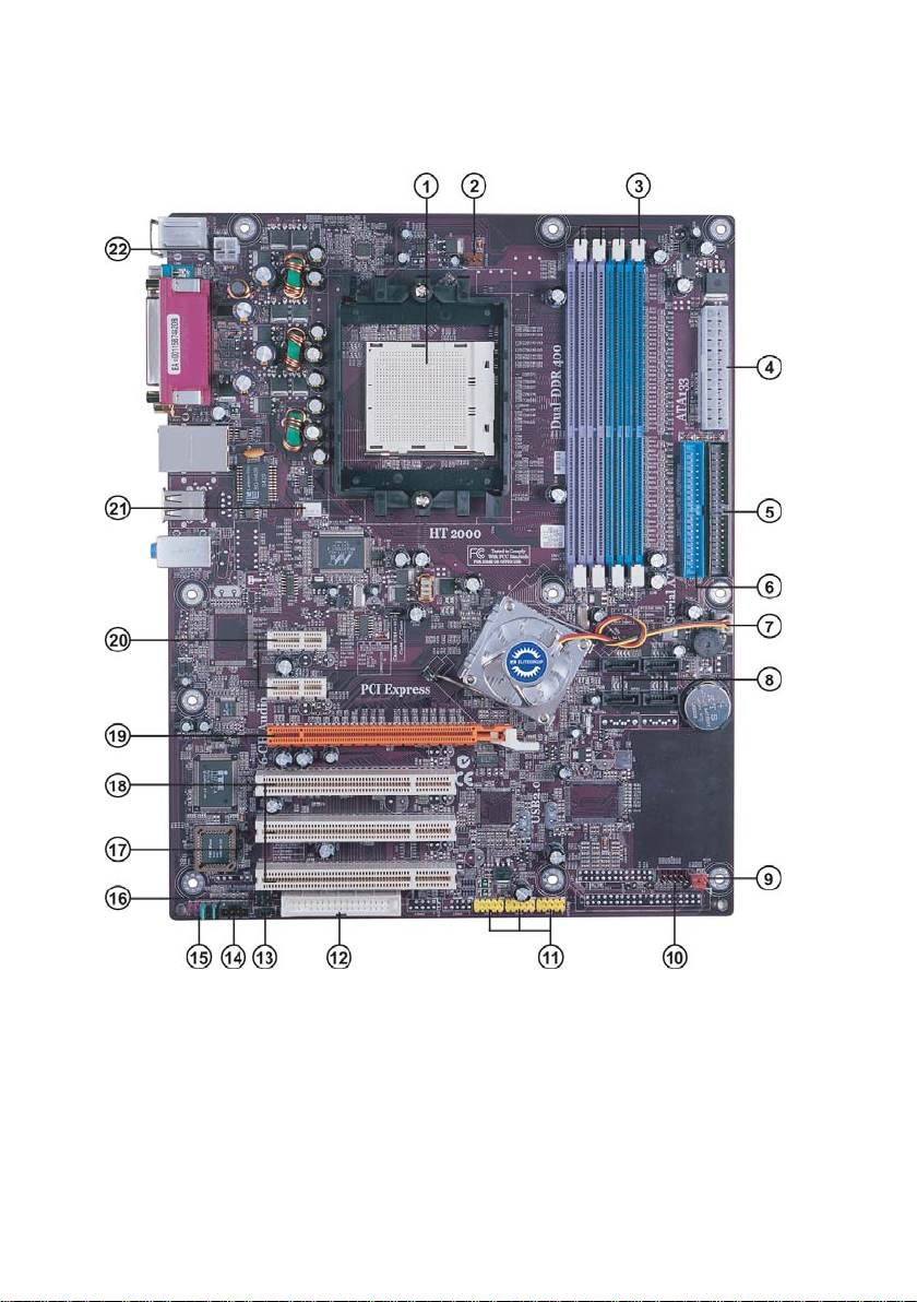
Motherboard Components
Introducing the Motherboard
Page 11

Table of Motherboard Components
LABEL COMPONENT
1 CPU Socket Socket 939 for AMD K8 processor
2 CPUFAN1 CPU cooling fan connector
3 DIMM1~4 184-pin DDR SDRAM slots
4 ATX1 Standard 24-pin ATX power connector
5 IDE2 Secondary IDE connector
6 IDE1 Primary IDE connector
7 NBFAN1 Northbridge cooling fan connector
8 SATA1~SATA4 Serial ATA connectors
9 JP1 Clear CMOS jumper
10 PANEL1 Front Panel switch/LED header
11 USB3 ~ 5 Front Panel USB headers
12 FDD1 Floppy disk drive connector
13 SJ1 Single color LED header
14 CDIN1 Analog Audio Input connector
15 AUDIO1 Front panel audio header
16 IR1 Infrared header
17 JP3 BIOS flash protect jumper
18 PCI1~3 32-bit add-on card slots
19 PCIE1 PCI Express x16 graphics card slot
20 PCIE2~3 PCI Express x1 slots
21 CASFAN1 Case cooling fan connector
22 ATX12V 4-pin +12V power connector
5
This concludes Chapter 1. The next chapter explains how to install the motherboard.
Introducing the Motherboard
Page 12

6
Memo
Introducing the Motherboard
Page 13

Chapter 2
Installing the Motherboard
Safety Precautions
• Follow these safety precautions when installing the motherboard
• Wear a grounding strap attached to a grounded device to avoid damage from
static electricity
• Discharge static electricity by touching the metal case of a safely grounded
object before working on the motherboard
• Leave components in the static-proof bags they came in
• Hold all circuit boards by the edges. Do not bend circuit boards
Choosing a Computer Case
There are many types of computer cases on the market. The motherboard complies with
the specifications for the ATX system case. First, some features on the motherboard are
implemented by cabling connectors on the motherboard to indicators and switches on the
system case. Make sure that your case supports all the features required. Secondly, NFORCE4A939 supports one or two floppy diskette drives and four enhanced IDE drives. Make sure
that your case has sufficient power and space for all drives that you intend to install.
Most cases have a choice of I/O templates in the rear panel. Make sure that the I/O
template in the case matches the I/O ports installed on the rear edge of the motherboard.
This motherboard carries an ATX form factor of 305 X 244 mm. Choose a case that
accommodates this form factor.
7
Installing the Motherboard in a Case
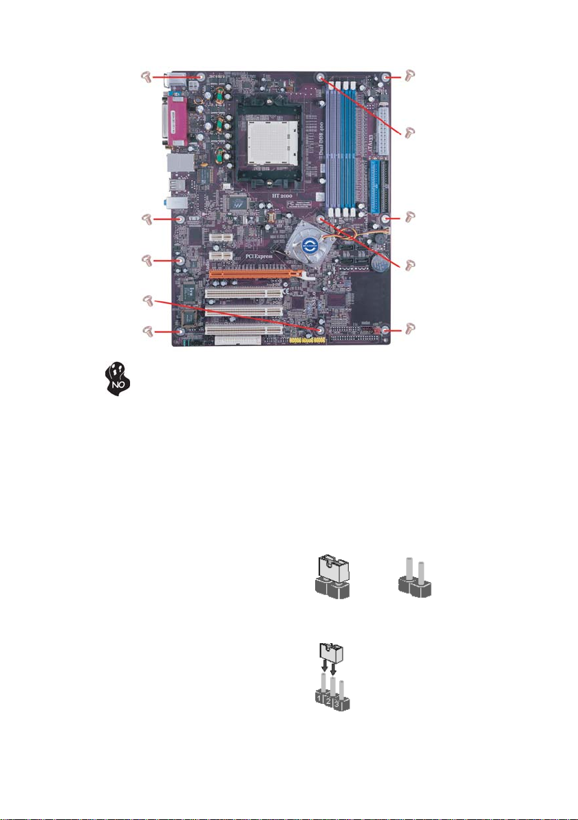
Refer to the following illustration and instructions for installing the motherboard in a case.
Most system cases have mounting brackets installed in the case, which correspond the holes
in the motherboard. Place the motherboard over the mounting brackets and secure the
motherboard onto the mounting brackets with screws.
Ensure that your case has an I/O template that supports the I/O ports and expansion slots
on your motherboard.
Installing the Motherboard
Page 14
8
Do not over-tighten the screws as this can stress the motherboard.
Checking Jumper Settings
This section explains how to set jumpers for correct configuration of the motherboard.
Setting Jumpers
Use the motherboard jumpers to set system configuration options. Jumpers with more than
one pin are numbered. When setting the jumpers, ensure that the jumper caps are placed on
the correct pins.
The illustrations show a 2-pin jumper. When
the jumper cap is placed on both pins, the
jumper is SHORT. If you remove the jumper
cap, or place the jumper cap on just one pin,
the jumper is OPEN.
This illustration shows a 3-pin jumper. Pins
1 and 2 are SHORT
SHORT OPEN
Installing the Motherboard
Page 15
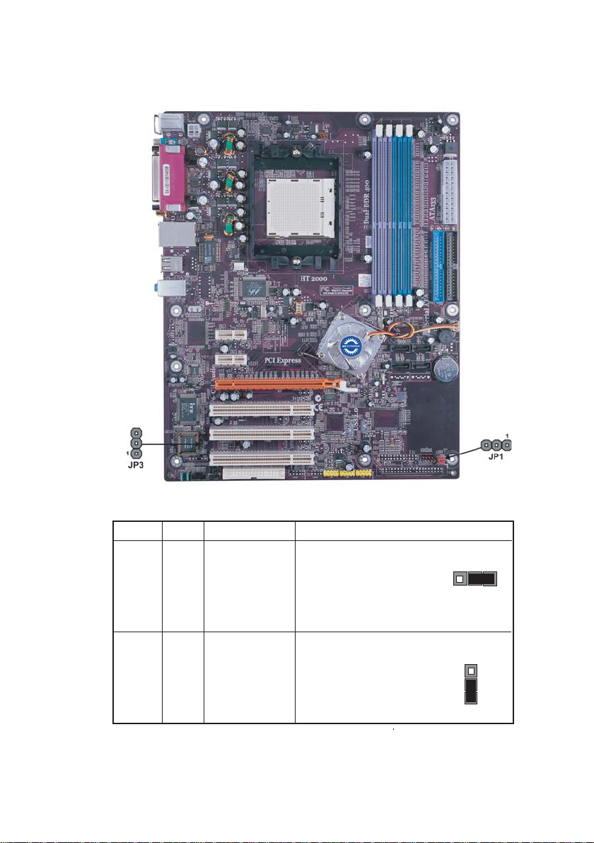
Checking Jumper Settings
The following illustration shows the location of the motherboard jumpers. Pin 1 is labeled.
9
Jumper Settings
Jumper
Type
3-pin CLEAR CMOS 1-2: NORMAL
JP1
3-pin
JP3 BIOS PROTECT
Description
Setting (default)
2-3: CLEAR
Before clearing the
CMOS, make sure to
turn the system off.
1-2: DISABLE
2-3: ENABLE
Installing the Motherboard
JP1
1
JP3
1
Page 16
10
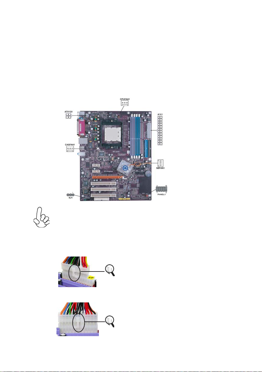
Connecting Case Components
After you have installed the motherboard into a case, you can begin connecting the motherboard components. Refer to the following:
1 Connect the CPU cooling fan cable to CPUFAN1.
2 Connect the case cooling fan connector to CASFAN1.
3 Connect the Northbridge cooling fan connector to NBFAN1.
4 Connect the case switches and indicator LEDs to the PANEL1, If there are 3
pins in the case LED cable, connect to SJ1.
5 Connect the standard power supply connector to A TX1.
6 Connect the auxiliary case power supply connector to ATX12V.
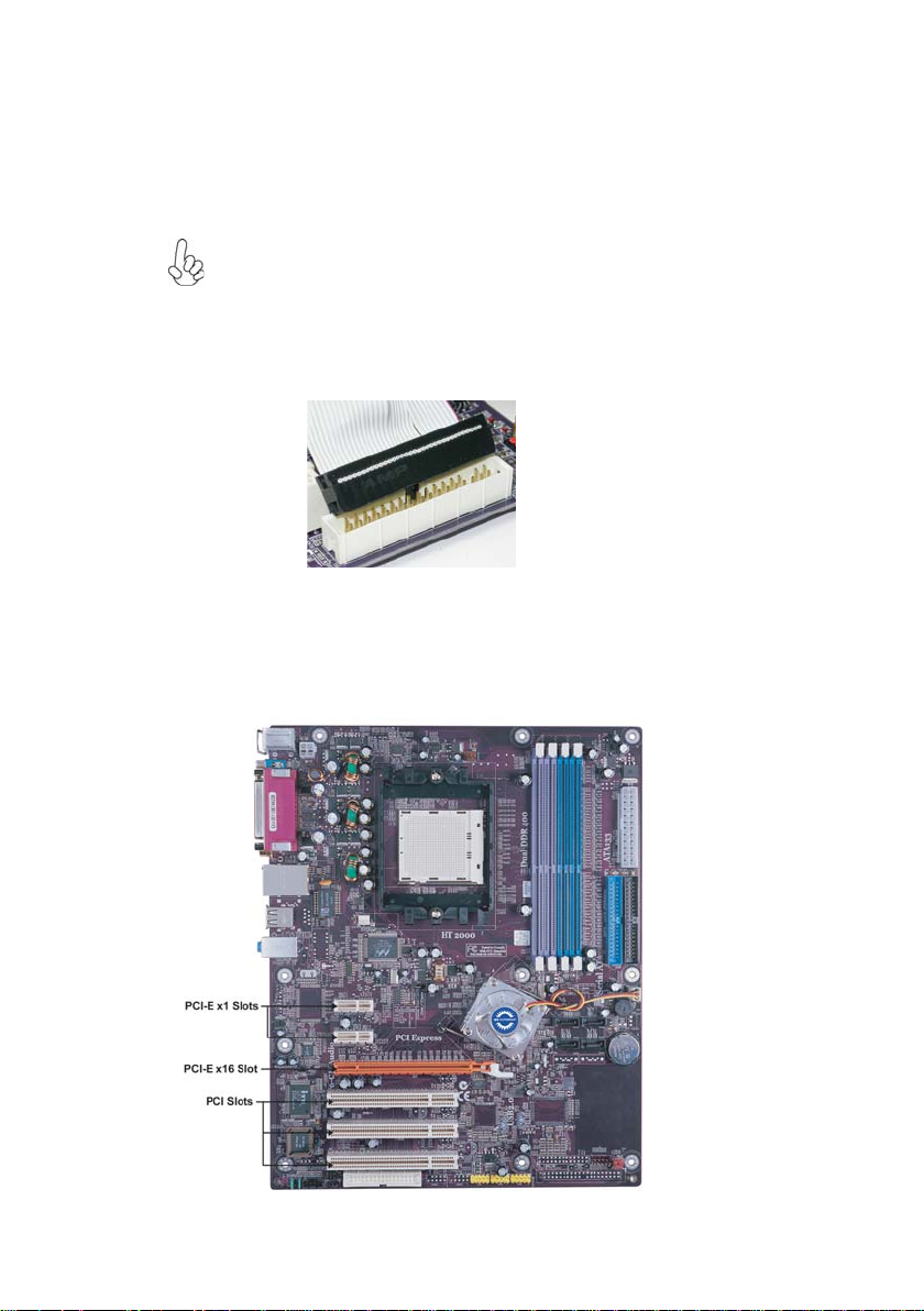
Connecting 20/24-pin power cable
Users please note that the 20-pin and 24-pin power cables can both be connected
to the ATX1 connector. With the 20-pin power cable, just align the 20-pin power
cable with the pin 1 of the ATX1 connector. However, using 20-pin power cable
may cause the system to become unbootable or unstable because of insufficient
electricity. A minimum power of 300W is recommended for a fully-configured
system.
With ATX v1.x power supply, users please note
that when installing 20-pin power cable, the
latche of power cable falls on the left side of
the ATX1 connector latch, just as the picture
shows.
20-pin power cable
With ATX v2.x power supply, users please note
that when installing 24-pin power cable, the
latches of power cable and the ATX1 match
perfectly.
24-pin power cable
Installing the Motherboard
Page 17
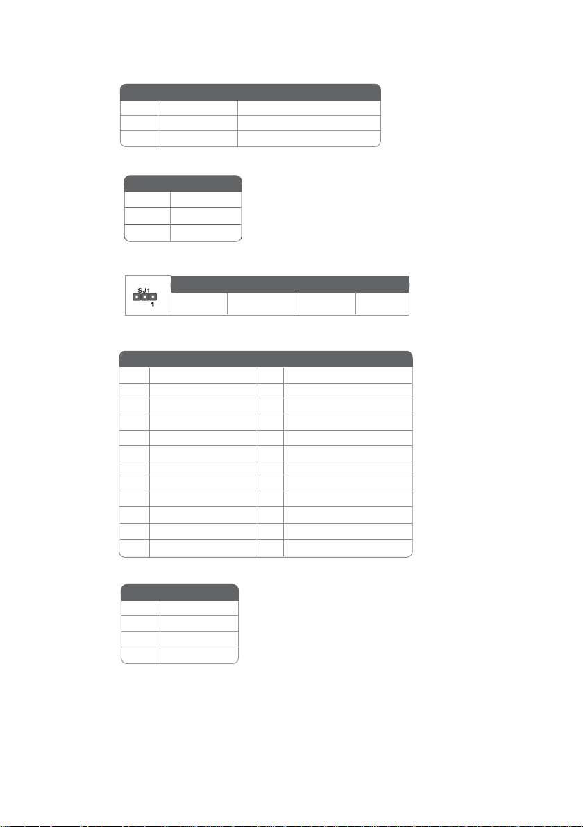
CPUFAN1/CASF AN1/NBF AN1: FAN Power Connectors
Pin Signal Name Pin
1 GND System Ground
2 +12V Power +12V
3 Sense Sensor
SJ1: Single-color LED header
Pin Signal Name
1 ACPI LED
Pin Signal Name
2 ACPI LED
3 5VSB
ACPI LED function
S0 S1 S3 S4/S5
Light Blinking Blinking Dark
A TX1: A TX 24-pin Power Connector
Pin Signal Name Pin Signal Name
1 +3.3V 13 +3.3V
2 +3.3V 14 -12V
3 Ground 15 COM
4 +5V 16 PS_ON
5 Ground 17 COM
6 +5V 18 COM
7 Ground 19 COM
8 PWRGD 20 -5V
9 +5VSB 21 +5V
10 +12V 22 +5V
11 +12V 23 +5V
12 +3.3V 24 COM
11
A TX12V: A TX 12V Power Connector
Pin Signal Name
1 Ground
2 Ground
3 +12V
4 +12V
Installing the Motherboard
Page 18
12
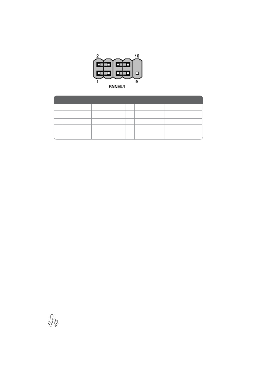
Front Panel Header
The front panel header (PANEL1) provides a standard set of switch and LED headers
commonly found on ATX or Micro ATX cases. Refer to the table below for information:
Pin Signal Name Function Pin Signal Name Function
1 HD_LED_P Hard disk LED+ 2 FP PWR/SLP *MSG LED+
3 HD_LED_N Hard disk LED-
5 RST_SW_N Reset Switch
7 RST_SW_P Reset Switch
9 RSVD Reserved
* MSG LED (dual color or single color)
Hard Drive Activity LED
Connecting pins 1 and 3 to a front panel mounted LED provides visual indication that data
is being read from or written to the hard drive. For the LED to function properly, an IDE
drive should be connected to the onboard IDE interface. The LED will also show activity
for devices connected to the SCSI (hard drive activity LED) connector.
Power/Sleep/Message waiting LED
4 FP PWR/SLP *MSG LED-
6 PWR_SW_P Power Switch
8 PWR_SW_N Power Switch
10 Key No pin
Connecting pins 2 and 4 to a single or dual-color, front panel mounted LED provides power
on/off, sleep, and message waiting indication.
Reset Switch
Supporting the reset function requires connecting pin 5 and 7 to a momentary-contact
switch that is normally open. When the switch is closed, the board resets and runs POST.
Power Switch
Supporting the power on/off function requires connecting pins 6 and 8 to a momentarycontact switch that is normally open. The switch should maintain contact for at least 50 ms
to signal the power supply to switch on or off. The time requirement is due to internal debounce circuitry. After receiving a power on/off signal, at least two seconds elapses before
the power supply recognizes another on/off signal.
Installing Hardware
Installing the Processor
Caution: When installing a CPU heatsink and cooling fan make sure that
you DO NOT scratch the motherboard or any of the surface-mount
resistors with the clip of the cooling fan. If the clip of the cooling fan
scrapes across the motherboard, you may cause serious damage to the
motherboard or its components.
Installing the Motherboard
Page 19

On most motherboards, there are small surface-mount resistors near the
processor socket, which may be damaged if the cooling fan is carelessly
installed.
Avoid using cooling fans with sharp edges on the fan casing and the clips.
Also, install the cooling fan in a well-lit work area so that you can clearly
see the motherboard and processor socket.
Before installing the Processor
This motherboard automatically determines the CPU clock frequency and system bus
frequency for the processor. You may be able to change these settings by making changes
to jumpers on the motherboard, or changing the settings in the system Setup Utility. We
strongly recommend that you do not over-clock processors or other components to run
faster than their rated speed.
Warning: Over-clocking components can adversely affect the reliability of
the system and introduce errors into your system. Over-clocking can
permanently damage the motherboard by generating excess heat in
components that are run beyond the rated limits.
This motherboard has a Socket 939 processor socket. When choosing a processor, consider
the performance requirements of the system. Performance is based on the processor design,
the clock speed and system bus frequency of the processor, and the quantity of internal
cache memory and external cache memory.
13
CPU Installation Procedure
The following illustration shows CPU installation components.
1 Install your CPU. Pull up the lever away from the
socket and lift up to 90-degree angle.
2 Locate the CPU cut edge (the corner with the pin
hold noticeably missing). Align and insert the CPU
correctly.
3 Press the lever down and apply thermal grease on
top of the CPU.
4 Put the CPU Fan down on the retention module and
snap the four retention legs of the cooling fan into
place.
5 Flip the levers over to lock the heat sink in place and
connect the CPU cooling Fan power cable to the
CPUFAN connector. This completes the installation.
To achieve better airflow rates and heat dissipation, we suggest that you use
a high quality fan with 4800 rpm at least. CPU fan and heatsink installation procedures may vary with the type of CPU fan/heatsink supplied. The
form and size of fan/heatsink may also vary.
Installing the Motherboard
Page 20
14
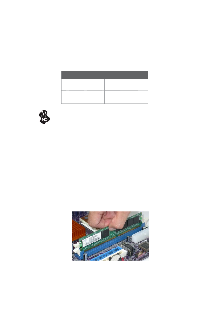
Installing Memory Modules
This motherboard accommodates four 184-pin unbuffered DIMM and supports DDR400/
333/266/200 DDR SDRAM. You must install at least one module in any of the four slots.
Each module can be installed with 256 MB to 1 GB of memory; the total memory capacity
is 4 GB.
DDR SDRAM memory module table
Memory module Memory Bus
DDR200 100MHz
DDR266 133MHz
DDR333 166MHz
DDR400 200MHz
Do not remove any memory module from its antistatic packaging until you
are ready to install it on the motherboard. Handle the modules only by
their edges. Do not touch the components or metal parts. Always wear a
grounding strap when you handle the modules.
Installation Procedure
Refer to the following to install the memory modules.
1 This motherboard supports unbuffered DDR SDRAM only.
2 Push the latches on each side of the DIMM slot down.
3 Align the memory module with the slot. The DIMM slots are keyed with
notches and the DIMMs are keyed with cutouts so that they can only be
installed correctly.
4 Check that the cutouts on the DIMM module edge connector match the notches
in the DIMM slot.
5 Install the DIMM module into the slot and press it firmly down until it seats
correctly. The slot latches are levered upwards and latch on to the edges of
the DIMM.
6 Install any remaining DIMM modules.
Installing the Motherboard
Page 21
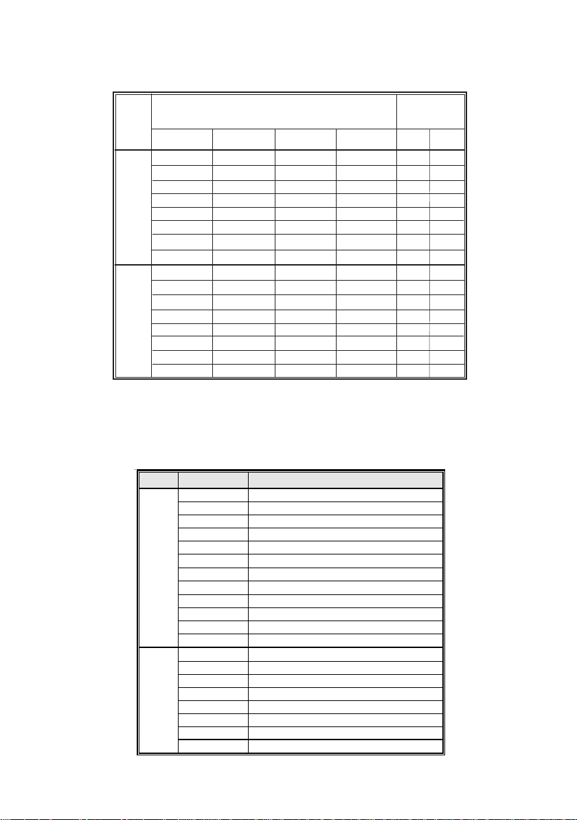
T able A: Unbuffered DIMM Support for 939-pin
15
N/A
N/A
N/A
N/A
N/A
N/A
N/A
N/A
N/A
N/A
Maximum
DRAM Speed
1T 2T
DDR400 DDR400
DDR400 DDR400
DDR400 DDR400
DDR400 DDR400
DDR333 DDR400
DDR200 DDR400
DDR200 DDR400
DDR200 DDR333
DDR400 DDR400
DDR400 DDR400
DDR400 DDR400
DDR400 DDR400
DDR333 DDR400
DDR200 DDR400
DDR200 DDR400
DDR200 DDR333
Data
Chip Selects
Bus
MEMCS_1L_L* MEMCS_2H_L* MEMCS_2L_L* MEMCS_2H_L*
64bits
128bits
Single rank
Double rank
N/A
N/A
Single rank
Single rank
Double rank
Double rank
Single rank
Double rank
N/A
N/A
Single rank
Single rank
Double rank
Double rank
N/A
N/A
N/A
N/A
N/A
N/A
N/A
N/A
Single rank
Double rank
N/A
N/A
Single rank
Single rank
Double rank
Double rank
N/A
N/A
Single rank
Double rank
Single rank
Double rank
Single rank
Double rank
N/A
N/A
Single rank
Double rank
Single rank
Double rank
Single rank
Double rank
Single rank
Double rank
Single rank
Double rank
Single rank
Double rank
Note for “*”: Memory types must be set to values consistent with system hardware.
Table B: DDR(memory module) QVL (Qualified Vendor List)
The following DDR400 memory modules have been tested and qualified for use with this
motherboard.
Size Vendor Model Name
256MB
512MB
GEIL GE08L3264D1WL5NKT3H71
Samsung K4H560838D-TCCC
Kingston D3208DL2T-5 0323PT01
Hynix HY5DU5656822BT-D43
Apacer AM3A568ACT-5A
Ramaxel MT-46V32M8 TG-5BC
GEIL G208L364D1TG5NKT3C
Samsung K4H560838E-TCCC
CORSAIR CMX256 3200C2PT
Kingston K4H560838D-TCC4
Ramaxel K4H560838D-TCC4
Kingston W942508BH-5
Kingston SAMSUNG K4H560838D-TCC4
Samsung K4H560838E-TCCC
GEIL GE16L6464D2 WL5NKT3H66
Kingmax KDL388P4EA-50
GEIL GE16L6464D2 WL5NKT3H66
HYNIX HY5DU56822BT-D43
TWINMOS M2G9J16AKATT9F083S9DT
CORSAIR CMX512-3200C2PT
Installing the Motherboard
Page 22
16
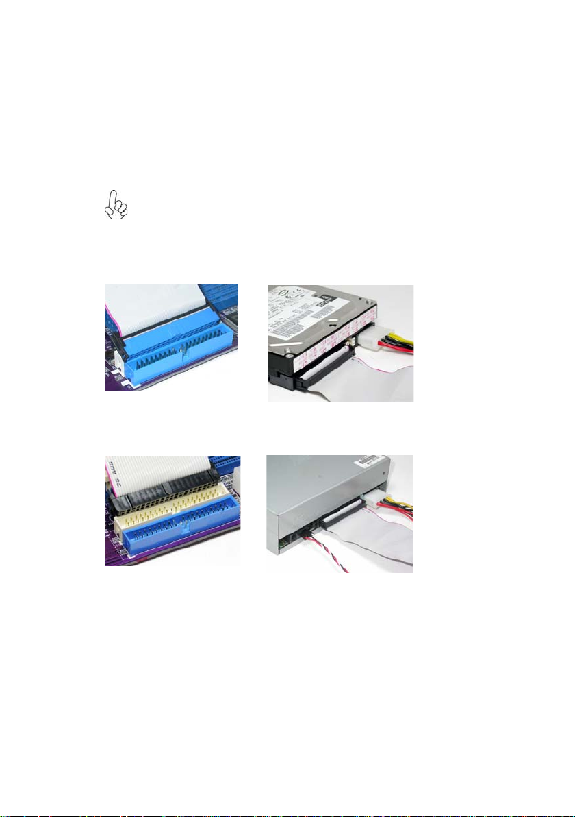
Installing a Hard Disk Drive/CD-ROM/SA T A Hard Drive
This section describes how to install IDE devices such as a hard disk drive and a CD-ROM
drive.
About IDE Devices
Your motherboard has a primary and secondary IDE channel interface (IDE1 and IDE2).
An IDE ribbon cable supporting two IDE devices is bundled with the motherboard.
You must orient the cable connector so that the pin1 (color) edge of the
cable correspoinds to the pin 1 of the I/O port connector.
IDE1: Primary IDE Connector
The first hard drive should always be connected to IDE1.
IDE2: Secondary IDE Connector
The second drive on this controller must be set to slave mode. The cinfiguration is the same
as IDE1.
IDE devices enclose jumpers or switches used to set the IDE device as MASTER or SLAVE.
Refer to the IDE device user’s manual. Installing two IDE devices on one cable, ensure that
one device is set to MASTER and the other device is set to SLAVE. The documentation of
your IDE device explains how to do this.
About UltraDMA
This motherboard supports UltraDMA 133/100/66. UDMA is a technology that accelerates the performance of devices in the IDE channel. To maximize performance, install IDE
devices that support UDMA and use 80-pin IDE cables that support UDMA 133/100/66.
Installing the Motherboard
Page 23
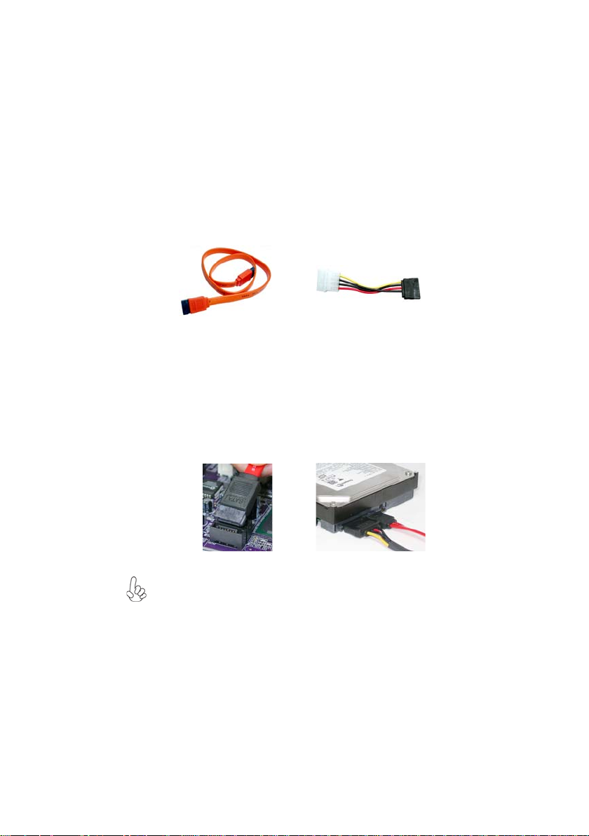
About SA TA Connectors
Your motherboard features two SATA connectors supporting a total of two drives. SATA
refers to Serial ATA (Advanced Technology Attachment) is the standard interface for the
IDE hard drives which are currently used in most PCs. These connectors are well designed
and will only fit in one orientation. Locate the SATA connectors on the motherboard and
follow the illustration below to install the SATA hard drives.
Installing Serial A TA Hard Drives
To install the Serial ATA (SATA) hard drives, use the SATA cable that supports the Serial
ATA protocol. This SATA cable comes with an SATA power cable. You can connect either
end of the SATA cable to the SATA hard drive or the connector on the motherboard.
17
SATA cable (optional)
Refer to the illustration below for proper installation:
1 Attach either cable end to the connector on the motherboard.
2 Attach the other cable end to the SATA hard drive.
3 Attach the SATA power cable to the SATA hard drive and connect the other
end to the power supply.
This motherboard does not support the “Hot-Plug” function.
SATA power cable (optional)
Installing the Motherboard
Page 24
18
Installing a Floppy Diskette Drive
The motherboard has a floppy diskette drive (FDD1) interface and ships with a diskette
drive ribbon cable that supports one or two floppy diskette drives. You can install a 5.25inch drive and a 3.5-inch drive with various capacities. The floppy diskette drive cable has
one type of connector for a 5.25-inch drive and another type of connector for a 3.5-inch
drive.
You must orient the cable connector so that the pin 1 (color) edge of the
cable corresponds to the pin 1 of the I/O port connector.
FDD1: Floppy Disk Connector
This connector supports the provided floppy drive ribbon cable. After connecting the single
end to the onboard floppy connector, connect the remaining plugs on the other end to the
floppy drives correspondingly.
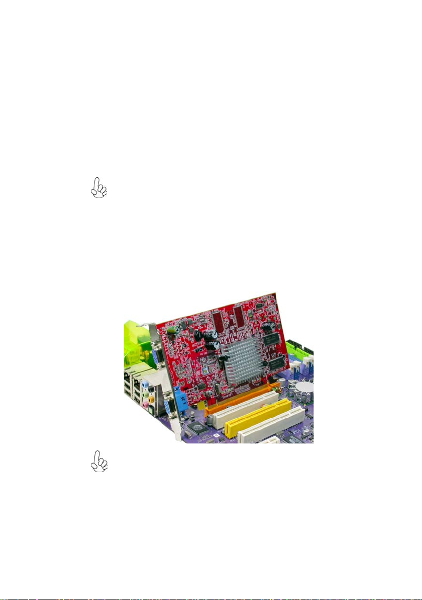
Installing Add-on Cards
The slots on this motherboard are designed to hold expansion cards and connect them to the
system bus. Expansion slots are a means of adding or enhancing the motherboard’s features
and capabilities. With these efficient facilities, you can increase the motherboard’s capabilities by adding hardware that performs tasks that are not part of the basic system.
Installing the Motherboard
Page 25
19
PCIE x1 Slots The two PCI Express x1 slots are fully compliant to the PCI Express
PCIE x16 Slot The PCI Express x16 slot is used to install an external PCI Express
PCI1~3 Slots
Follow these instructions to install an add-on card:
1 Remove a blanking plate from the system case corresponding to the slot you
2 Install the edge connector of the add-on card into the expansion slot. Ensure
3 Secure the metal bracket of the card to the system case with a screw.
Base Specification revision 1.0a as well.
graphics card that is fully compliant to the PCI Express Base Specification revision 1.0a.
This motherboard is equipped with three standard PCI slots. PCI stands
for Peripheral Component Interconnect and is a bus standard for expansion cards, which for the most part, is a supplement of the older ISA bus
standard. The PCI slots on this board are PCI v2.3 compliant.
Before installing an add-on card, check the documentation for the card
carefully. If the card is not Plug and Play, you may have to manually
configure the card before installation.
are going to use.
that the edge connector is correctly seated in the slot.
For some add-on cards, for example graphics adapters and network adapters, you have to install drivers and software before you can begin using the
add-on card.
Installing the Motherboard
Page 26

20
Connecting Optional Devices
Refer to the following for information on connecting the motherboard’s optional devices:
AUDIO1: Front Panel Audio header
This header allows the user to install auxiliary front-oriented microphone and line-out ports
for easier access.
Pin Signal Name
1 AUD_MIC Front Panel Microphone input signal
2 AUD_GND Ground used by Analog Audio Circuits
3 AUD_MIC_BIAS Microphone Power
4 AUD_VCC Filtered +5V used by Analog Audio Circuits
5 AUD_F_R Right Channel audio signal to Front Panel
6 AUD_RET_R Right Channel Audio signal to Return from Front Panel
7 REVD Reserved
8 Key No Pin
9 AUD_F_L Left Channel Audio signal to Front Panel
10 AUD_RET_L Left Channel Audio signal to Return from Front Panel
Pin Signal Name
Function
CDIN1: Analog Audio Input connector
Pin Signal Name
1 CD in_L CD In left channel
2 GND Ground
3 GND Ground
4 CD in_R CD In right channel
Function
Installing the Motherboard
Page 27

SA TA1~SA T A4: Serial A T A connectors
These connectors are use to support the new Serial ATA devices for the highest date transfer
rates (150 MB/s), simpler disk drive cabling and easier PC assembly. It eliminates limitations
of the current Parallel ATA interface. But maintains register compatibility and software
compatibility with Parallel ATA.
21
Pin Signal Name
Pin Signal Name Function
1 Ground 2 TX+
Pin Signal Name
3 TX- 4 Ground
5 RX- 6 RX+
7 Ground - -
USB3~USB5: Front Panel USB headers
The motherboard has four USB ports installed on the rear edge I/O port array. Additionally,
some computer cases have USB ports at the front of the case. If you have this kind of case,
use auxiliary USB connector to connect the front-mounted ports to the motherboard.
Pin Signal Name
Function
1 USBPWR Front Panel USB Power
2 USBPWR Front Panel USB Power
3 USB_FP_P0- USB Port 0 Negative Signal
4 USB_FP_P1- USB Port 1 Negative Signal
5 USB_FP_P0+ USB Port 0 Positive Signal
6 USB_FP_P1+ USB Port 1 Positive Signal
7 GND Ground
8 GND Ground
9 Key No pin
10 NC Not connected
Please make sure that the USB cable has the same pin assignment as indicated above. A different pin assignment may cause damage or system hangup.
IR1: Infrared port
The motherboard supports an Infrared (IR1) data port. Infrared ports allow the wireless
exchange of information between your computer and similarly equipped devices such as
printers, laptops, Personal Digital Assistants (PDAs), and other computers.
Pin Signal Name
Pin Signal Name Function
1 Not assigned Not assigned
2 KEY No pin
3 +5V IR Power
4 GND Ground
5 IRTX IrDA serial output
6 IRRX IrDA serial output
Function
Installing the Motherboard
Page 28

22
Connecting I/O Devices
The backplane of the motherboard has the following I/O ports:
PS2 Mouse Use the upper PS/2 port to connect a PS/2 pointing device.
PS2 Keyboard Use the lower PS/2 port to connect a PS/2 keyboard.
Parallel Port (LPT1) Use LPT1 to connect printers or other parallel communications
devices.
RCA1(optional) Use RCA1 to connect external digital audio output devices.
OPT1(optional) Use OPT1 to connect external digital audio output devices.
Serial Port Use the COM port to connect serial devices such as mice or
(COM1) fax/modems. COM1 is identified by the system as COM1/3.
LAN Port (optional) Connect an RJ-45 jack to the LAN port to connect your computer
to the Network.
USB Ports Use the USB ports to connect USB devices.
Audio Ports Use the three audio ports to connect audio devices. The first jack
This concludes Chapter 2. The next chapter covers the BIOS.
is for stereo line-in signal. The second jack is for stereo line-out
signal. The third jack is for microphone.
Installing the Motherboard
Page 29

Chapter 3
Using BIOS
About the Setup Utility
The computer uses the latest Award BIOS with support for Windows Plug and Play. The
CMOS chip on the motherboard contains the ROM setup instructions for configuring the
motherboard BIOS.
The BIOS (Basic Input and Output System) Setup Utility displays the system’s configuration status and provides you with options to set system parameters. The parameters are
stored in battery-backed-up CMOS RAM that saves this information when the power is
turned off. When the system is turned back on, the system is configured with the values you
stored in CMOS.
The BIOS Setup Utility enables you to configure:
• Hard drives, diskette drives and peripherals
• Video display type and display options
• Password protection from unauthorized use
• Power Management features
The settings made in the Setup Utility affect how the computer performs. Before using the
Setup Utility, ensure that you understand the Setup Utility options.
This chapter provides explanations for Setup Utility options.
23
The Standard Configuration
A standard configuration has already been set in the Setup Utility. However, we recommend
that you read this chapter in case you need to make any changes in the future.
This Setup Utility should be used:
• when changing the system configuration
• when a configuration error is detected and you are prompted to make changes
to the Setup Utility
• when trying to resolve IRQ conflicts
• when making changes to the Power Management configuration
• when changing the password or making other changes to the Security Setup
Entering the Setup Utility
When you power on the system, BIOS enters the Power-On Self Test (POST) routines.
POST is a series of built-in diagnostics performed by the BIOS. After the POST routines are
completed, the following message appears:
Using BIOS
Page 30

24
Press DEL to enter SETUP
Pressing the delete key accesses the BIOS Setup Utility:
Phoenix-AwardBIOS CMOS Setup Utility:
Standard CMOS Features
Advanced BIOS Features
Advanced Chipset Features
Integrated Peripherals
Power Management Setup
PnP/PCI Configurations
PC Health Status
Esc: Quit
F10: Save & Exit Setup
Time, Date, Hard Disk Type...
Load Performance
Load Optimized Defaults
Set Supervisor Password
Set User Password
Save & Exit Setup
Exit Without Saving
BIOS Navigation Keys
The BIOS navigation keys are listed below:
KEY FUNCTION
Enter
+/-/PU/PD
ESC Exits the current menu
F1
F2
F5
F6
F7
F9
F10
Move
Select
Value
General Help
Item Help
Previous Values
Fail-Safe Defaults
Optimized Defaults
Menu in BIOS
Save
: Select Item
Using BIOS
Page 31

Updating the BIOS
You can download and install updated BIOS for this motherboard from the manufacturer’s
Web site. New BIOS provides support for new peripherals, improvements in performance,
or fixes for known bugs. Install new BIOS as follows:
1 If your motherboard has a BIOS protection jumper, change the setting to allow
BIOS flashing.
2 If your motherboard has an item called Firmware Write Protect in Advanced
BIOS features, disable it. (Firmware Write Protect prevents BIOS from being
overwritten.
3 Create a bootable system disk. (Refer to Windows online help for information
on creating a bootable system disk.)
4 Download the Flash Utility and new BIOS file from the manufacturer’s Web
site. Copy these files to the system diskette you created in Step 3.
5 Turn off your computer and insert the system diskette in your
computer’s diskette drive. (You might need to run the Setup Utility and change
the boot priority items on the Advanced BIOS Features Setup page, to force
your computer to boot from the floppy diskette drive first.)
6 At the A:\ prompt, type the Flash Utility program name and press <Enter>.
7 Type the filename of the new BIOS in the “File Name to Program” text box.
Follow the onscreen directions to update the motherboard BIOS.
8 When the installation is complete, remove the floppy diskette from the diskette
drive and restart your computer. If your motherboard has a Flash BIOS jumper ,
reset the jumper to protect the newly installed BIOS from being overwritten.
Using BIOS
When you start the Setup Utility, the main menu appears. The main menu of the Setup
Utility displays a list of the options that are available. A highlight indicates which option is
currently selected. Use the cursor arrow keys to move the highlight to other options. When
an option is highlighted, execute the option by pressing <Enter>.
25
Some options lead to pop-up dialog boxes that prompt you to verify that you wish to
execute that option. Other options lead to dialog boxes that prompt you for information.
Some options (marked with a triangle
values for the option. Use the cursor arrow keys to scroll through the items in the submenu.
In this manual, default values are enclosed in parenthesis. Submenu items are denoted by a
triangle
.
) lead to submenus that enable you to change the
Using BIOS
Page 32

26
Standard CMOS Features
This option displays basic information about your system.
Phoenix-AwardBIOS CMOS Setup Utility
Standard CMOS Features
Date (mm:dd:yy) Wed, Oct. 25 2004
Time (hh:mm:ss) 9 : 33 : 26
IDE Channel 0 Master [WDC WD800bb-22FJA0]
IDE Channel 0 Slave [None]
IDE Channel 1 Master [None]
IDE Channel 1 Slave [None]
IDE Channel 2 Master [None]
IDE Channel 3 Master [None]
IDE Channel 4 Master [None]
IDE Channel 5 Master [None]
Drive A [1.44M, 3.5 in.]
Floppy 3 Mode Select [Disabled]
Video [EGA/VGA]
Halt On [All, But Keyboard]
Base Memory 640K
: Move Enter: Select +/-/PU/PD:Value F10:Save ESC:Exit F1: General Help
F5:Previous Values F6:Fail-Safe Defaults F7:Optimized Defaults
Date and Time
The Date and Time items show the current date and time on the computer. If
you are running a Windows OS, these items are automatically updated whenever you make
changes to the Windows Date and Time Properties utility.
IDE Devices (None)
Your computer has two IDE channels (Primary and Secondary) and each channel can be
installed with one or two devices (Master and Slave). Use these items to
configure each device on the IDE channel.
Item Help
Menu Level
Change the day, month,
year and century
Press <Enter> to display the IDE submenu:
Phoenix-AwardBIOS CMOS Setup Utility
IDE Channel 0 Slave
IDE HDD Auto-Detection [Press Enter]
IDE Channel 0 Slave [Auto]
Access Mode [Auto]
Capacity 0MB
Cylinder 0
Head 0
Precomp 0
Landing Zone 0
Sector 0
: Move Enter: Select +/-/PU/PD:Value F10:Save ESC:Exit F1: General Help
F5:Previous Values F6:Fail-Safe Defaults F7:Optimized Defaults
Item Help
Menu Level
To auto-detect the
HDD’s size, head... on
this channel
IDE HDD Auto-Detection
Press <Enter> while this item is highlighted to prompt the Setup Utility to automatically
detect and configure an IDE device on the IDE channel.
Using BIOS
Page 33

If you are setting up a new hard disk drive that supports LBA mode, more
than one line will appear in the parameter box. Choose the line that lists
LBA for an LBA drive.
IDE Channel 0/1/2/3/4/5 Master & IDE Channel 0/1 Slave
Leave this item at Auto to enable the system to automatically detect and configure IDE
devices on the channel. If it fails to find a device, change the value to Manual and then
manually configure the drive by entering the characteristics of the drive in the items
described below.
Before attempting to configure a hard disk drive, ensure that you have the
configuration information supplied by the manufacturer of your hard drive.
Incorrect settings can result in your system not recognizing the installed
hard disk.
Access Mode (Auto)
This item defines ways that can be used to access IDE hard disks such as LBA (Large Block
Addressing). Leave this value at Auto and the system will automatically decide the fastest
way to access the hard disk drive.
Press <Esc> to return to the Standard CMOS Features page.
Drive A (1.44M, 3.5 in.)
These items define the characteristics of any diskette drive attached to the system.
You can connect one or two diskette drives.
Floppy 3 Mode Select (Disabled)
Floppy 3 Mode refers to a 3.5-inch diskette with a capacity of 1.2MB. Floppy 3 mode
is sometimes used in Japan.
Video (EGA/VGA)
This item defines the video mode of the system. This motherboard has a built-in VGA
graphics system; you must leave this item at the default value.
Halt On (All, But Keyboard)
This item defines the operation of the system POST (Power On Self Test) routine. You
can use this item to select which types of errors in the POST are sufficient to halt the
system.
Base Memory, Extended Memory, and Total Memory
These items are automatically detected by the system at start up time. These are
display-only fields. You cannot make changes to these fields.
27
Using BIOS
Page 34

28
Advanced BIOS Features
This option defines advanced information about your system.
Hard Disk Boot Priority [Press Enter]
CPU Internal Cache [Enabled]
External Cache [Enabled]
Quick Power On Self T est [Enabled]
First Boot Device [Floppy]
Second Boot Device [Hard Disk]
Third Boot Device [CDROM]
Boot Other Device [Enabled]
Swap Floppy Drive [Disabled]
Boot Up Floppy Seek [Disabled]
Boot Up NumLock Status [On]
Gate A20 Option [Fast]
AT A 66/100 IDE Cable Msg. [Enabled]
Typematic Rate Setting [Disabled]
Typematic Rate (Chars/Sec0 6
X
Typematic Delay (Msec) 2 5 0
X
Security Option [Setup]
APIC Mode [Enabled]
: Move Enter: Select +/-/PU/PD:Value F10:Save ESC:Exit F1: General Help
F5:Previous Values F6:Fail-Safe Defaults F7:Optimized Defaults
Hard Disk Boot Priority (Press Enter)
Scroll to this item and press <Enter> to view the following screen:
1. Cho M :WDC WD800BB-22F JA0
2. Bootable Add-in Cards
Phoenix-AwardBIOS CMOS Setup Utility
Advanced BIOS Features
Phoenix-AwardBIOS CMOS Setup Utility
Hard Disk Boot Priority
Item Help
Menu Level
Item Help
Menu Level
Use < > or < >
to select a device, then
press <+> to move it
up, or <-> to move it
down the list. Press
<ESC> to exit this
menu.
: Move PU/PD+/-/:Change Priority F10:Save ESC:Exit
CPU Internal Cache (Enabled)
All processors that can be installed in this motherboard use internal level 1 (L1) cache
memory to improve performance. Leave this item at the default value for better performance.
External Cache (Enabled)
Most processors that can be installed in this system use external level 2 (L2) cache memory
to improve performance. Leave this item at the default value for better performance.
Quick Power On Self Test (Enabled)
Enable this item to shorten the power on testing (POST) and have your system start
up faster. You might like to enable this item after you are confident that your system
hardware is operating smoothly.
Using BIOS
Page 35

First/Second/Third Boot Device (Floppy/Hard Disk/CDROM)
Use these three items to select the priority and order of the devices that your system
searches for an operating system at start-up time.
Boot Other Device (Enabled)
When enabled, the system searches all other possible locations for an operating system if
it fails to find one in the devices specified under the First, Second, and Third boot devices.
Swap Floppy Drive [Disabled]
If you have two floppy diskette drives in your system, this item allows you to swap the
assigned drive letters so that drive A becomes drive B, and drive B becomes drive A.
Boot Up Floppy Seek (Disabled)
If this item is enabled, it checks the size of the floppy disk drives at start-up time. You
don’t need to enable this item unless you have a legacy diskette drive with 360K capacity.
Boot Up NumLock Status (On)
This item defines if the keyboard Num Lock key is active when your system is started.
Gate A20 Option (Fast)
This item defines how the system handles legacy software that was written for an earlier
generation of processors. Leave this item at the default value.
ATA 66/100 IDE Cable Msg. (Enabled)
This item enables or disables the display of the ATA 66/100 Cable MSG.
Typematic Rate Setting (Disabled)
If this item is enabled, you can use the following two items to set the typematic rate and the
typematic delay settings for your keyboard.
• Typematic Rate (Chars/Sec): Use this item to define how many characters
per second are generated by a held-down key.
• Typematic Delay (Msec): Use this item to define how many milliseconds must
elapse before a held-down key begins generating repeat characters.
Security Option (Setup)
If you have installed password protection, this item defines if the password is required at
system start up, or if it is only required when a user tries to enter the Setup Utility.
APIC Mode (Enabled)
This item allows you to enable or disable the APIC (Advanced Programmable Interrupt
Controller) mode. APIC provides symmetric multi-processing (SMP) for systems, allowing
support for up to 60 processors.
OS Select For DRAM > 64 MB (Non-OS2)
This item is only required if you have installed more than 64 MB of memory and you are
running the OS/2 operating system. Otherwise, leave this item at the default.
Small Logo (EPA) Show (Disabled)
Enables or disables the display of the EPA logo during boot.
29
Using BIOS
Page 36

30
Summary Screen Show ( Enabled)
This item determines whether the summary system information will be showed during bootup.
Advanced Chipset Features
These items define critical timing parameters of the motherboard. You should leave the
items on this page at their default values unless you are very familiar with the technical
specifications of your system hardware. If you change the values incorrectly, you may
introduce fatal errors or recurring instability into your system.
Phoenix-AwardBIOS CMOS Setup Utility
Advanced Chipset Features
CPU Frequency [200.0]
HT Frequency [Auto]
HT Width [16
DRAM Configuration [Press Enter]
CPU Spread Sprectrum [Center Spread]
SAT A Spread S prectrum [Disabled]
PCIE Spread Sprectrum [Disabled]
CPU Thermal-Throttling [50%]
CPU Voltage Control [Normal]
DIMM Voltage Control [2.63V]
System BIOS Cacheable [Disabled]
: Move Enter: Select +/-/PU/PD:Value F10:Save ESC:Exit F1: General Help
F5:Previous Values F6:Fail-Safe Defaults F7:Optimized Defaults
16]
Item Help
Menu Level
DRAM timing and control
CPU Frequency (200.0)
This item enables users to manually over-clock the CPU frequency, ranging from 200.0
to 209.5
HT Frequency (Auto)
This item enables users to manually set up the HyperTransport frequency, ranging from
Auto, 1x, to 5x.
HT Width ( 16 16)
This item enables users to manually set up the HyperTransport width, width ranging
from 8 down 8 up to 16 down 16 up.
DRAM Configuration (Press Enter)
Scroll to this item and press <Enter> to view the following screen:
Phoenix-AwardBIOS CMOS Setup Utility
DRAM Configuration
Timing Mode [Auto]
Memlock index value (Mhz) 200Mhz
X
CAS# latency (Tcl) 2.5
X
Min RAS# active time (Tras) 8T
X
RAS# to CAS# delay(Trcd) 4 T
X
Row precharge Time (Trp) 4 T
X
Item Help
Menu Level
Places an artificial
memory clock limit on the
system. Memory is
prevented from running
faster than this frequency
: Move Enter: Select +/-/PU/PD:Value F10:Save ESC:Exit F1: General Help
F5:Previous Values F6:Fail-Safe Defaults F7:Optimized Defaults
Using BIOS
Page 37

Timing Mode (Auto)
This item enables you to specify the DRAm timing mode to be configured automatically or
manually.
• Memclock index value (Mhz) (200Mhz): When DDR Timing Setting by is
set to Manual, use this item to set the DRAM frequency.
• CAS# latency (Tcl) (2.5): This item determines the operation of DDR SDRAM
memory CAS (column address strobe). It is recommended that you leave this
item at the default value. The 2T setting requires faster memory that secifically
supports this mode.
• Min RAS# active time (Tras) (8T): This item specifies the minumum RAS#
active time.
• RAS# to CAS# delay (Trcd) (4T): This item specifies the RAS# to CAS#
delay to Rd/Wr command to the same bank.
• Row Precharge Time (Trp) (4T): This item specifies the Row precharge to
Active or Auto-Refresh of the same bank.
Press <Esc> to return to the Advanced Chipset Features page.
CPU Spread Spectrum (Center Spread)
This item, when enabled, can significantly reduce the EMI (Electromagnetic Interference)
generated by the CPU.
SATA Spread Spectrum (Disabled)
This item, when enabled, can significantly reduce the EMI (Electromagnetic Interference)
generated by the SATA.
PCIE Spread Spectrum (Disabled)
This item, when enabled, can significantly reduce the EMI (Electromagnetic Interference)
generated by the PCIE.
CPU THRM-Throttling (50.0%)
Use this item to specify the CPU speed (at percentage) to slow down the CPU when it
reach the predetermined overheat temperature.
CPU Voltage Control (Normal)
This item enables users to tune up the CPU voltage manually, ranging from Normal,
+25mV, +50mV, +75mV, +100mV, +125mV, ..........to +375mV.
DIMM Voltage Control (2.63V)
This item enables users to tune up the DDR DIMM voltage manually, ranging from 2.55V,
2.63V, 2.71V, 2.79V, 2.87V, 2.95V, 3.03V, to 3.11V.
System BIOS Cacheable (Disabled)
This item enabels users to enable or disable the system BIOS cache.
31
Using BIOS
Page 38

32
Integrated Peripherals
These options display items that define the operation of peripheral components on
the system’s input/output ports.
Phoenix-AwardBIOS CMOS Setup Utility
Integrated Peripherals
IDE Function Setup [Press Enter]
RAID Config [Press Enter]
Onboard Device [Press Enter]
Super IO Device [Press Enter]
: Move Enter: Select +/-/PU/PD:Value F10:Save ESC:Exit F1: General Help
IDE Function Setup (Press Enter)
F5:Previous Values F6:Fail-Safe Defaults F7:Optimized Defaults
Scroll to this item and press <Enter> to view the following screen:
Phoenix-AwardBIOS CMOS Setup Utility
IDE Function Setup
OnChip IDE Channel0 [Enabled]
Primary Master PIO [Auto]
Primary Slave PIO [Auto]
Primary Master UDMA [Auto]
Primary Slave UDMA [Auto]
OnChip IDE Channel1 [Enabled]
Secondary Master PIO [Auto]
Secondary Slave PIO [Auto]
Secondary Master UDMA [Auto]
Secondary Slave UDMA [Auto]
IDE DMA transfer access [Enabled]
Serial-ATA 1 [Enabled]
Serial-ATA 2 [Enabled]
IDE Prefetch Mode [Enabled]
IDE HDD Block Mode [Enabled]
: Move Enter: Select +/-/PU/PD:Value F10:Save ESC:Exit F1: General Help
F5:Previous Values F6:Fail-Safe Defaults F7:Optimized Defaults
On-Chip IDE Channel 0/1 (Enabled)
Use these items to enable or disable the PCI IDE channels that are integrated on the
motherboard.
Primary/Secondary Master/Slave PIO (Auto)
Each IDE channel supports a master device and a slave device. These four items let you
assign the kind of PIO (Programmed Input/Output) was used by the IDE devices. Choose
Auto to let the system auto detect which PIO mode is best, or select a PIO mode from 0-4.
Primary/Secondary Master/Slave UltraDMA (Auto)
Each IDE channel supports a master device and a slave device. This motherboard supports
UltraDMA technology, which provides faster access to IDE devices.
If you install a device that supports UltraDMA, change the appropriate item on this list to
Auto. You may have to install the UltraDMA driver supplied with this motherboard in order
to use an UltraDMA device.
Item Help
Menu Level
Item Help
Menu Level
Using BIOS
Page 39

IDE DMA transfer access (Enabled)
This item allows you to enable the transfer access of the IDE DMA then burst onto the
PCI bus and nonburstable transactions do not.
Serial-ATA 1/2 (Enabled)
This item allows you to enable or disable the onboard SATA 1/2 devices.
IDE Prefetch Mode (Enabled)
The onboard IDE drive interface supports IDE prefetching, for faster drive access. If you
install a primary and secondary add-in IDE interface, set this field to Disabled if the
interface does not support prefetching.
IDE HDD Block Mode (Enabled)
Block mode is also called block transfer, multiple commands, or multiple sector read/write.
If your IDE hard drive supports block mode, select Enabled for automatic detection of the
optimal number of block read/write per sector the drive can support.
Press <Esc> to return to the Integrated Peripherals page.
RAID Config (Press Enter)
Scroll to this item and press <Enter> to view the following screen:
Phoenix-AwardBIOS CMOS Setup Utility
RAID Config
33
RAID Enable [Disabled]
x
IDE Primary Master RAID Disabled
x
IDE Primary Slave RAID Disabled
x
IDE Secondary Master RAID Disabled
x
IDE Secondary Slave RAID Disabled
x
SAT A 1 Primary RAID Disabled
x
SAT A 1 Secondary RAID Disabled
x
SAT A 2 Primary RAID Disabled
x
SAT A 2 Secondary RAID Disabled
: Move Enter: Select +/-/PU/PD:Value F10:Save ESC:Exit F1: General Help
F5:Previous Values F6:Fail-Safe Defaults F7:Optimized Defaults
Item Help
Menu Level
RAID Enable (Disabled)
This item allows you to enable or disable the onboard RAID function of RAID function of
RAID supporting devices.
• IDE Primary/Secondary Master/Slave RAID (Disabled): These four items
enable or disable the IDE Primary/Secondary RAID.
• SATA 1/2 Primary/Secondary RAID (Disabled): These four items enable
or disable the SATA 1/2 Primary/Secondary RAID.
Press <Esc> to return to the Integrated Peripherals page.
Using BIOS
Page 40

34
Onboard Device (Press Enter)
Scroll to this item and press <Enter> to view the following screen:
Phoenix-AwardBIOS CMOS Setup Utility
Onboard Device
Init Display First [PCI Slot]
OnChip USB [V1.1+V2.0V]
USB Keyboard Support [Enabled]
USB Mouse Support [Enabled]
AC97 Audio [Auto]
Onboard Giga Lan [Auto]
: Move Enter: Select +/-/PU/PD:Value F10:Save ESC:Exit F1: General Help
F5:Previous Values F6:Fail-Safe Defaults F7:Optimized Defaults
Item Help
Menu Level
Init Display First (PCI Slot)
This item allows users to set the initial display device for the system.
Onchip USB (V1.1+V2.0)
This item enables users to enable or disable the onchip USB function, setting it to be USB1.1
or USB2.0 compatible.
USB Keyboard Support (Enabled)
Enables this item if you plan to use a keyboard connected through the USB port in a legacy
operating system (such as DOS) that does not support Plug and Play.
USB Mouse Support (Enabled)
Enable this item if you plan to use a mouse connected through the USB port in a legacy
operating system (such as DOS) that does not support Plug and Play.
AC’ 97 AUDIO (Auto)
Enables and disables the onboard audio chip. Disable this item if you are going to install a
PCI audio add-in card.
Onboard Giga LAN (Auto)
Enables or disables the onboard Giga LAN function.
Press <Esc> to return to the Integrated Peripherals page.
Using BIOS
Page 41

SuperIO Device (Press Enter)
Scroll to this item and press <Enter> to view the following screen:
Phoenix-AwardBIOS CMOS Setup Utility
SuperIO Device
35
Onboard FDC Controller [Enabled]
Onboard Serial Port 1 [3F8/IRQ4]
Onboard Serial Port 2 [2F8/IRQ3]
UART Mode Select [IRDA]
UR2 Duplex Mode [Half]
Onboard Parallel Port [378/IRQ7]
Parallel Port Mode [ECP]
ECP Mode Use DMA [3]
: Move Enter: Select +/-/PU/PD:Value F10:Save ESC:Exit F1: General Help
F5:Previous Values F6:Fail-Safe Defaults F7:Optimized Defaults
Item Help
Menu Level
Onboard FDC Controller (Enabled)
This option enables the onboard floppy disk drive controller.
Onboard Serial Port 1/2 (3F8/IRQ4, 2F8/IRQ3)
This option is used to assign the I/O address and interrupt request (IRQ) for onboard serial
port 1/2.
UART Mode Select (IRDA)
This field is available if the Onboard Serial Port 2 field is set to any option but Disabled.
. UART Mode Select enables you to select the infrared communication protocol-IrDA,
ASKIR or SCR.
UR2 Duplex Mode (Half)
This field is available when UART Mode is set to either ASKIR or IrDA. This item enables
you to determine the infrared function of the onboard infrared chip. The options are Full
and Half (default). Full-duplex means that you can transmit and send information
simultaneously. Half-duplex is the transmission of data in both directions, but only one
direction at a time.
Onboard Parallel Port (378/IRQ7)
This option is used to assign the I/O address and interrupt request (IRQ) for the onboard
parallel port.
Parallel Port Mode (ECP)
Enables you to set the data transfer protocol for your parallel port. There are four options:
SPP (Standard Parallel Port), EPP (Enhanced Parallel Port), ECP (Extended Capabilities
Port) and ECP+EPP.
SPP allows data output only. Extended Capabilities Port (ECP) and Enhanced Parallel Port
(EPP) are bi-directional modes, allowing both data input and output. ECP and EPP modes
are only supported with EPP- and ECP-aware peripherals.
ECP Mode Use DMA (3)
When the onboard parallel port is set to ECP mode, the parallel port can use DMA 3 or
DMA 1.
Press <Esc> to return to the Integrated Peripherals page.
Using BIOS
Page 42

36
Power Management Setup
This option lets you control system power management. The system has various powersaving modes including powering down the hard disk, turning off the video, suspending
to RAM, and software power down that allows the system to be automatically resumed
by certain events.
ACPI Suspend Type [S3(STR)]
Video Off Method [DPMS Support]
HDD Power Down [Disabled]
HDD Down In Suspend [Disabled]
Soft-Off by PBTN [Instant-Off]
Power On By Button [Enabled]
Power On By Mouse [Disabled]
Power On By Keyboard [Disabled]
KB Power ON Password Enter
X
Hot Key Power ON Ctrl-F1
X
PWRON After PWR-Fail [Off]
Resume By PCI PME [Enabled]
Resume By Ring [Disabled]
Power-On by Alarm [Disabled]
X
Day of Month Alarm 0
X
Time (hh:mm:ss) Alarm 0 : 0 : 0
AMD K8 Cool’n’Quiet control [Auto]
Hammer Fid control [StartUp]
: Move Enter: Select +/-/PU/PD:Value F10:Save ESC:Exit F1: General Help
F5:Previous Values F6:Fail-Safe Defaults F7:Optimized Defaults
ACPI Suspend Type (S3(STR)
Use this item to define how your system suspends. In the default, S3 (STR), the suspend
mode is a suspend to RAM, i.e., the system shuts down with the exception of a refresh
current to the system memory.
Video Off Method (DPMS Supported)
This item defines how the video is powered down to save power. This item is set to DPMS
(Display Power Management Software) by default.
HDD Power Down (Disabled)
The IDE hard drive will spin down if it is not accessed within a specified length of time.
HDD Down In Suspend (Disabled)
This item enables or disables whether the IDE hard drive to be down in suspend mode.
Soft-Off by PBTN (Instant-Off)
Under ACPI (Advanced Configuration and Power management Interface) you can create a
software power down. In a software power down, the system can be resumed by Wake Up
Alarms. This item lets you install a software power down that is controlled by the power
button on your system. If the item is set to Instant-Off, then the power button causes a
software power down. If the item is set to Delay 4 Sec. then you have
to hold the power button down for four seconds to cause a software power down.
Power On By Button (Enabled)
Enable or disable the function of waking up the system by the power-on button.
Power On By Mouse (Disabled)
Enable or disable the function of waking up the system by the mouse activity.
Phoenix-AwardBIOS CMOS Setup Utility
Power Management Setup
Item Help
Menu Level
Using BIOS
Page 43

Power On By Keyboard (Disabled)
Enable or disable the function of waking up the system by the keyboard activity.
• KB Power ON Password (Enter):Use this item to decide whether to enter the
password when waking from keyboard.
• Hot Key Power ON (Ctrl+F1): Use this item to allocate the hot key to wake up
the system.
PWRON After PWR-Fail (Off)
This item enables your computer to automatically restart or return to its last operating
status.
Resume By PCI PME (Enabled)
This item allows users to enable or disable PCI activity to wake up the system from a
power saving mode.
Resume By Ring (Disabled)
This item allows users to enable or disable LAN or modem activity to wake up the system
from a power saving mode.
Power-On by Alarm (Disabled)
This item allows users to enable or disable the alarm to wake up the system. If set to
Enabled, users can specify the specific day of month and the exact time to power up the
system.
AMD K8 Cool’n’Quiet control (Auto)
This item helps the system to lower the frequency when CPU idles. When the frequency
decreases, the temperature will drop automatically as well.
Hammer Fid control (StartUp)
This item allows users to set the CPU fid value manually, ranging from x4 to x21.
37
Using BIOS
Page 44

38
PNP/PCI Configurations
These options configure how PnP (Plug and Play) and PCI expansion cards operate in
your system. Both the the ISA and PCI buses on the motherboard use system IRQs
(Interrup ReQuests) and DMAs (Direct Memory Access). You must set up the IRQ and
DMA assignments correctly through the PnP/PCI Configurations Setup utility for the
motherboard to work properly. Selecting PnP/PCI Configurations on the main program
screen displays this menu:
Phoenix-AwardBIOS CMOS Setup Utility
PnP/PCI Configurations
Reset Configuration Data [Disabled]
Resources Controlled By [Auto(ESCD)]
X
IRQ Resources Press Enter
PCI/VGA Palette Snoop [Disabled]
** PCI Express relative items**
Maximum Payload Size [4096]
: Move Enter: Select +/-/PU/PD:Value F10:Save ESC:Exit F1: General Help
F5:Previous Values F6:Fail-Safe Defaults F7:Optimized Defaults
Item Help
Menu Level
Default is Disabled. Select
Enabled to reset Extended
System Configuration Data
ESCD) when you exit Setup
if you have installed a new
add-on and the system
reconfiguration has caused
such a serious conflict that
the OS cannot boot
Reset Configuration Data (Disabled)
If you enable this item and restart the system, any Plug and Play configuration data
stored in the BIOS Setup is cleared from memory.
Resources Controlled By Auto (Auto(ESCD))
You should leave this item at the default Auto (ESCD). Under this setting, the system
dynamically allocates resources to Plug and Play devices as they are required.
If you cannot get a legacy ISA (Industry Standard Architecture) expansion card to work
properly, you might be able to solve the problem by changing this item to Manual, and
then opening up the IRQ Resources submenu.
• IRQ Resources:In the IRQ Resources submenu, if you assign an IRQ to
Legacy ISA, then that Interrupt Request Line is reserved for a legacy ISA
expansion card. Press <Esc> to close the IRQ Resources submenu.
In the Memory Resources submenu, use the first item Reserved Memory Base
to set the start address of the memory you want to reserve for the ISA
expansion card. Use the section item Reserved Memory Length to set the
amount of reserved memory. Press <Esc> to close the Memory Resources
submenu.
PCI/VGA Palette Snoop (Disabled)
This item is designed to overcome problems that can be caused by some non-standard
VGA cards. This board includes a built-in VGA system that does not require palette
snooping so you must leave this item disabled.
Maximum Payload Size (4096)
This item specifies the maximum payload size for the PCI Express function.
Using BIOS
Page 45

PC Health Status
On motherboards that support hardware monitoring, this item lets you monitor the
parameters for critical voltages, temperatures and fan speeds.
Phoenix-AwardBIOS CMOS Setup Utility
PC Health Status
Shutdown T emperature [Disabled]
CPU Vcore Voltage
Vcc 3V 3.31V
Vcc 2.5V 2.94V
Vcc 1.5V 1.45V
Vcc 1.2V 1.1V
Vcc +12V 11.77V
5VSB 4.83V
Voltage Battery 2.99V
System Temperature 38oC
CPU Temperature 58oC
CPUFAN1 Speed 2481 RPM
NBFAN1 Speed 6250 RPM
CASFAN1 Speed 0 RPM
: Move Enter: Select +/-/PU/PD:Value F10:Save ESC:Exit F1: General Help
F5:Previous Values F6:Fail-Safe Defaults F7:Optimized Defaults
Shutdown Temperature (Disabled)
Enables you to set the maximum temperature the system can reach before powering down.
System Component Characteristics
These fields provide you with information about the systems current operating status.
You cannot make changes to these fields.
• CPU Vcore Voltage
• Voltage Battery
• System Temperature
• CPU T emperature
• CPUFAN1 Speed
• NBFAN1 Speed
• CASFAN1 Speed
Item Help
Menu Level
39
Using BIOS
Page 46

40
Load Performance
This option opens a dialog box that lets you install performance defaults for all appropriate
items in the Setup Utility: Press <Y> and the <Enter> to install the defaults. Press
<N> and then <Enter> to not install the defaults. If you want to make your system for
greater effectiveness, then install the performance defaults. If you only want to install
performance defaults for a specific option, select and display that option, and then press
<F6>.
Warning: To load Best Performance Settings may make your system become
unstable or unbootable.
Load Optimized Defaults
This option opens a dialog box that lets you install optimized defaults for all appropriate
items in the Setup Utility. Press <Y> and then <Enter> to install the defaults. Press
<N> and then <Enter> to not install the defaults. The optimized defaults place demands on the system that may be greater than the performance level of the components,
such as the CPU and the memory. You can cause fatal errors or instability if you install
the optimized defaults when your hardware does not support them. If you only want to
install setup defaults for a specific option, select and display that option, and then press
<F7>.
Users please remain the factory BIOS default setting of “Load optimized
Defaults” when install Operation System onto your system.
Set Supervisor/User Password
When this function is selected, the following message appears at the center of the screen
to assist you in creating a password.
ENTER PASSWORD
Type the password, up to eight characters, and press <Enter>. The password typed now
will clear any previously entered password from CMOS memory. You will be asked to
confirm the password. Type the password again and press <Enter>. You may also press
<Esc> to abort the selection.
To disable password, just press <Enter> when you are prompted to enter password. A
message will confirm the password being disabled. Once the password is disabled, the
system will boot and you can enter BIOS Setup freely.
P ASSWORD DISABLED
If you have selected “System” in “Security Option” of “BIOS Features Setup” menu,
you will be prompted for the password every time the system reboots or any time you try
to enter BIOS Setup.
If you have selected “Setup” at “Security Option” from “BIOS Features Setup” menu,
you will be prompted for the password only when you enter BIOS Setup.
Supervisor Password has higher priority than User Password. You can use Supervisor
Password when booting the system or entering BIOS Setup to modify all settings. Also
you can use User Password when booting the
system or entering BIOS Setup but can not modify any setting if Supervisor Password
is enabled.
Using BIOS
Page 47

Save & Exit Setup
Highlight this item and press <Enter> to save the changes that you have made in the
Setup Utility and exit the Setup Utility. When the Save and Exit dialog box appears,
press <Y> to save and exit, or press <N> to return to the main menu.
Exit Without Saving
Highlight this item and press <Enter> to discard any changes that you have made in the
Setup Utility and exit the Setup Utility. When the Exit Without Saving dialog box
appears, press <Y> to discard changes and exit, or press <N> to return to the main
menu.
If you have made settings that you do not want to save, use the “Exit
Without Saving” item and press <Y> to discard any changes you have
made.
This concludes Chapter 3. Refer to the next chapter for information on the software
supplied with the motherboard.
41
Using BIOS
Page 48

42
Memo
Using BIOS
Page 49

Chapter 4
Using the Motherboard Software
About the Software CD-ROM
The support software CD-ROM that is included in the motherboard package contains all the
drivers and utility programs needed to properly run the bundled products. Below you can find
a brief description of each software program, and the location for your motherboard
version. More information on some programs is available in a README file, located in the
same directory as the software.
Never try to install all software from folfer that is not specified for use with your
motherboard.
Before installing any software, always inspect the folder for files named README.TXT,
INSTALL.TXT, or something similar. These files may contain important information that
is not included in this manual.
Auto-installing under Windows 2000/XP
The Auto-install CD-ROM makes it easy for you to install the drivers and software for your
motherboard.
If the Auto-install CD-ROM does not work on your system, you can still install
drivers through the file manager for your OS (for example, Windows Explorer). Refer to the Utility Folder Installation Notes later in this chapter.
43
The support software CD-ROM disc loads automatically under Windows 2000/XP. When
you insert the CD-ROM disc in the CD-ROM drive, the autorun feature will automatically
bring up the install screen. The screen has three buttons on it, Setup, Browse CD and Exit.
If the opening screen does not appear; double-click the file “setup.exe” in the
root directory.
Using the Motherboard Software
Page 50

44
Setup Tab
Setup
Browse CD
Exit The EXIT button closes the Auto Setup window.
Application Tab
Lists the software utilities that are available on the CD.
Read Me Tab
Displays the path for all software and drivers available on the CD.
Click the Setup button to run the software installation program. Select
from the menu which software you want to install.
The Browse CD button is the standard Windows command that allows
you to open Windows Explorer and show the contents of the support
CD.
Before installing the software from Windows Explorer, look for a file
named README.TXT, INSTALL.TXT or something similar. This file
may contain important information to help you install the software
correctly.
Some software is installed in separate folders for different operating
systems, such as DOS, WIN NT, or WIN98/95. Always go to the correct
folder for the kind of OS you are using.
In install the software, execute a file named SETUP.EXE or INSTALL.EXE
by double-clicking the file and then following the instructions on the
screen.
Running Setup
Follow these instructions to install device drivers and software for the motherboard:
1. Click Setup. The installation program begins:
The following screens are examples only. The screens and driver lists will
be different according to the motherboard you are installing.
The motherboard identification is located in the upper left-hand corner.
Using the Motherboard Software
Page 51

2. Click Next. The following screen appears:
3. Check the box next to the items you want to install. The default optionsare recommended.
4. Click Next run the Installation Wizard. An item installation screen appears:
45
5. Follow the instructions on the screen to install the items.
Drivers and software are automatically installed in sequence. Follow the onscreen instructions, confirm commands and allow the computer to restart a few times to complete the
installation.
Using the Motherboard Software
Page 52

46
Manual Installation
Insert the CD in the CD-ROM drive and locate the PATH.DOC file in the root directory.
This file contains the information needed to locate the drivers for your motherboard.
Look for the chipset and motherboard model; then browse to the directory and path to
begin installing the drivers. Most drivers have a setup program (SETUP.EXE) that automatically detects your operating system before installation. Other drivers have the setup
program located in the operating system subfolder.
If the driver you want to install does not have a setup program, browse to the operating
system subfolder and locate the readme text file (README.TXT or README.DOC) for
information on installing the driver or software for your operating system.
Utility Software Reference
All the utility software available from this page is Windows compliant. They are provided
only for the convenience of the customer. The following software is furnished under license
and may only be used or copied in accordance with the terms of the license.
These software(s) are subject to change at anytime without prior notice.
Please refer to the support CD for available software.
AMI/AWARD Flash Utility
This utility lets you erase the system BIOS stored on a Flash Memory chip on the motherboard,
and lets you copy an updated version of the BIOS to the chip. Proceed with caution when
using this program. If you erase the current BIOS and fail to write a new BIOS, or write a new
BIOS that is incorrect, your system will malfunction. Refer to Chapter 3, Using BIOS for
more information.
WinFlash Utility
The WinFlash utility is a Windows version of the DOS BIOS flash writer utility. The utility
enables you to flash the system BIOS stored on a Flash Memory chip on the motherboard
while in a Windows environment. This utility is currently available for WINXP\2000. To
install the WinFlash utility, run AFUWIN.EXE (AMI) or WINFLASH.EXE (Award) from
the following directory: \UTILITY\WINFLASH AMI or Award.
This concludes Chapter 4.
Using the Motherboard Software
Page 53

Multi-Language Translation
Français
Le NVIDIA® CrushK8-04 (CK8-04) comporte une seule puce avec une fiabilité et des
performances prouvées.
Mémoire
• Architecture mémoire DDR double canal
• 4 x sockets DIMM SDRAM DDR, 184 broches prenant en charge jusqu’à 4
Go
• Prend en charge les SDRAM DDR sans mémoire tampon
DDR400/333/266/200
Chipset
• HyperTransport x16 liaisons haute et basse jusqu’à 1,0 GHz sur le processeurs AMD Sempron/Athlon 64/Athlon 64 FX /Athlon 64 X2
• Interface PCI 2.3, prenant en charge jusqu’à cinq logements PCI
• Deux contrôleurs SATA séparés avec PHYs intégrés, chacun prenant en
charge deux lecteurs en mode maître
• IEEE 802.3 NVIDIA MAC pour 1000BASE-T/100BASE-T/10BASE-T
• USB 2.0 EHCI et USB 1.1 OHCI, prenant en charge jusqu’à dix ports
• Contrôleur Fast ATA-133 IDE
• Interface AC’97 2.3, prenant en charge la fonction S/PDIF directe et
standard, fonctionnalité audio améliorée
• Prend en charge Gigabit/Fast Ethernet/Ethernet
Caractéristiques
Processeur
Cette carte mère utilise un socket de 939 broches ayant les caractéristiques suivantes :
• Reçoit les processeurs AMD Sempron/Athlon 64/Athlon 64 FX /Athlon 64
X2
• Prend en charge des vitesses d’interface HyperTransportTM (HT) allant
jusqu’à 2000MT/s
La Technologie HyperTransport
TM
est une liaison point à point entre deux matériels, elle
permet à des circuits intégrés d’échanger des informations à des vitesses bien plus élevées
que ne le permettent les technologies à interconnexions actuellement disponibles.
CODEC Audio AC’97
• CODEC full-duplex 16 bits avec vitesse d’échantillonnage de 48MHz
• Conforme aux spécifications AC’97 2.3
• Prend en charge la vitesse d’échantillonnage double (96KHz) de la lecture
audio DVD
Cette carte mère prend en charge la maîtrise de bus Ultra DMA avec des vitesses de transfert de
133/100/66 Mo/s.
La carte mère est livrée avec les options d’extensions suivantes:
• Un logement PCI Express x16
• Deux logements PCI Express x1
• Trois logements PCI 32 bits
• Deux embases IDE prenant en charge quatre périphériques IDE
• Une interface de lecteur de disquette
• Quatre connecteurs SATA à 7 broches
Options d’extension
Page 54

Multi-Language Translation
Français
LAN interne (optionnel)
• Conforme 10/100/1000BASE-T IEEE 802.3
• Prend en charge les interfaces GMII, TBI, comptage de broches réduit GMII
(RGMII), comptage de broches réduit TBI (RTBI), et série GMII (SGMII)
• Auto-Négotiation conforme IEEE 802.3u
• Empêche les paquets sortants avec adresses source IP usurpées et offre
des capacités de journalisation/configuration
Le LAN interne offre les caractéristiques suivantes:
E/S intégrées
La carte mère possède un jeu complet de ports d’E/S et de connecteurs:
• Deux ports PS/2 pour souris et clavier
• Un port série
• Un port parallèle
• Quatre ports USB
• Un port LAN (optionnel)
• Prises audio pour microphone, ligne d’entrée et ligne de sortie
Microprogramme BIOS
La carte mère utilise Award BIOS qui permet aux utilisateurs de configurer de nombreuses
caractéristiques du système comprenant les suivantes:
• Gestion de l’alimentation
• Alarmes de réveil
• Paramètres de CPU
• Synchronisation du CPU et de la mémoire
Le microprogramme peut aussi être utilisé pour définir les paramètres pour les vitesses d’horloges
de différents processeurs.
Certaines spécifications matérielles et éléments de logiciels peuvent être modifiés
sans avertissement.
Page 55

Multi-Language Translation
Deutsche
NVIDIA® CrushK8-04 (CK8-04) ist ein Single-Chip mit bewiesener Zuverlässigkeit und
Leistung.
Speicher
• Dualkanal DDR-Speicherarchitektur
• 4 x 184-Pin, DDR SDRAM DIMM-Sockets unterstützen bis zu 4 GB
• Unterstützt DDR400/333/266/200 ungepufferte DDR SDRAM
AC’97 Audio CODEC
Chipsatz
• HyperTransport x16 Up- und Down-Links mit bis zu 1.0 GHz zur AMD Sempron/Athlon 64/Athlon 64 FX/Athlon 64 X2 Prozessoren auf
• PCI 2.3 Interface, unterstützt bis zu fünf PCI-Steckplätze
• Zwei separate SATA Controller mit integrierten PHYs, wobei jedes zwei
Laufwerke im Master-Modus unterstützt
• IEEE 802.3 NVIDIA MAC für 1000BASE-T/100BASE-T/10BASE-T
• USB 2.0 EHCI und USB 1.1 OHCI, unterstützen bis zu zehn Ports
• Fast ATA-133 IDE-Controller
• AC’97 2.3 Interface, unterstützt S/PDIFP Pass-Through-Funktion und
Standard, erweiterte Audio-Funktionalität
• Unterstützt Gigabit/Fast Ethernet/Ethernet
• 16-Bit Stereo-Vollduplex CODEC mit einer Samplingrate von 48MHz
• Entspricht AC’97 2.3 Spezifikationen
• Unterstützt bei der DVD-Audiowiedergabe die doppelte Samplingrate
(96KHz)
Feature
Prozessor
Dieses Motherboard verwendet einen 939-Pin Socket mit den folgenden Eigenschaften:
• Nimmt AMD Sempron/Athlon 64/Athlon 64 FX/Athlon 64 X2 Prozessoren
auf
• Unterstützt bis zu 2000MT/s HyperTransportTM(HT) InterfaceGeschwindigkeiten
HyperTransport
TM
Technologie ist ein Punkt-zu-Punkt Link zwischen zwei Geräten. Es
ermöglicht integrierten Schaltkreisen einen Informationsaustausch mit wesentlich höherer
Geschwindigkeit als bei gängigen Interconnect-Technologien.
Dieses Motherboard unterstützt Ultra DMA Bus-Mastering mit Transferraten von 133/100/
66MB/s.
Das Motherboard bietet die folgenden Erweiterungsoptionen:
• Ein PCI Express x16 Steckplatz
• Zwei PCI Express x1 Steckplätze
• Drei 32-Bit PCI-Steckplätze
• Zwei IDE-Header, die vier IDE-Geräte unterstützen
• Ein Steckplatz für ein Diskettenlaufwerk
• Vier 7-Pin SATA-Stecker
Erweiterungsoptionen
Page 56

Multi-Language Translation
Deutsche
Integriertes LAN (optional)
• Entspricht 10/100/1000BASE-T IEEE 802.3
• Unterstützt GMII, TBI, Reduced Pin-Count GMII (RGMII), Reduced PinCount TBI (RTBI) und serielle GMII (SGMII) Interfaces
• Auto-Negotiation gemäß IEEE 802.3u
• Verhindert das Aussenden von Datenpaketen mit gespooften IPHerkunftsadressen und bietet Protokoll-/Konfigurationsfähigkeiten
Das integrierte LAN bietet folgende Features:
Integrierte I/O-Schnittstellen
Das Motherboard verfügt über einen kompletten Satz von I/O-Schnittstellen und Anschlüssen:
• Zwei PS/2-Schnittstellen für Tastatur und Maus
• Eine serielle Schnittstelle
• Eine parallele Schnittstelle
• Vier USB- Schnittstellen
• Eine LAN-Schnittstelle (optional)
• Audiobuchsen für Mikrofon, Line-In und Line-Out
BIOS Firmware
Dieses Motherboard setzt das Award BIOS ein, mit dem der Anwender viele
Systemeigenschaften selbst konfigurieren kann, einschließlich der folgenden:
• Energieverwaltung
• Wake-up Alarm
• CPU-Parameter
• CPU- und Speichertiming
Mit der Firmware können auch Parameter für verschiedene Prozessortaktgeschwindigkeiten
eingestellt werden.
Einige Hardware- und Software-Spezifikationen können jederzeit und ohne
vorherige Ankündigung geändert werden.
Page 57

Multi-Language Translation
Italiano
Il single chip NVIDIA® CrushK8-04 (CK8-04) offre collaudata affidabilità e prestazioni
sicure.
Memoria
• Architettura di memoria DDR Dual-channel
• 4 prese DIMM per DDR SDRAM a 184 pin con supporto di fino a 4 GB
• Supporto di DDR SDRAM DDR400/333/266/200 senza buffer
CODEC Audio AC’97
Chipset
• Link Up e Down HyperTransport x16 a fino 1,0 GHz alla processori AMD
Sempron/Athlon 64/Athlon 64 FX/Athlon 64 X2
• Interfaccia PCI 2.3 con supporto di fino a cinque slot PCI
• Due controller SATA separati con PHY integrati, ciascuno con supporto di
due drive in modalità master
• MAC IEEE 802.3 NVIDIA per 1000BASE-T/100BASE-T/10BASE-T
• EHCI USB 2.0 e OHCI USB 1.1 con supporto di fino a dieci porte
• Controller IDE ATA-133 a elevata velocità
• Interfaccia AC’97 2.3 con supporto di funzione pass-through S/PDIF e
funzionalità audio potenziata standard
• Supporto di Gigabit/Fast Ethernet/Ethernet
• CODEC full-duplex stereo a 16 bit con velocità di campionamento di 48
KHz
• Conforme alle specifiche AC’97 2.3
• Supporto di velocità di campionamento doppia (96 KHz) per la
riproduzione audio di DVD
Caratteristiche
Processore
La scheda madre utilizza una presa a 939 pin che offre le seguenti caratteristiche:
• Compatibilità con processori AMD Sempron/Athlon 64/Athlon 64 FX/
Athlon 64 X2
• Supporto di velocità di interfaccia HyperTransportTM (HT) fino a 2000 MT/s
La tecnologia HyperTransport
TM
consente il collegamento point-to-point fra due dispositivi
e quindi un trasferimento di informazioni tra circuiti integrati molto più veloce di quanto sia
possibile con le attuali tecnologie di interconnessione.
La scheda madre supporta la funzionalità di bus mastering Ultra DMA con velocità di
trasferimento di 133/100/66 MB/s.
La scheda madre è dotata delle seguenti opzioni di espansione:
• Uno slot PCI Express x16
• Due slot PCI Express x1
• Tre slot PCI a 32 bit
• Due connettori IDE per il supporto di 4 componenti IDE
• Un’interfaccia per unità disco floppy
• Quattro connettori SATA a 7 pin
Opzioni di espansione
Page 58

Multi-Language Translation
Italiano
LAN integrata (opzionale)
• Conforme a IEEE 802.3 10/100/1000BASE-T
• Supporto di interfacce GMII, TBI, GMII a ridotto numero di pin (RGMII), TBI
a ridotto numero di pin (RTBI) e GMII seriali (SGMII)
• Auto-Negotiation conforme a IEEE 802.3u
• Impedisce la trasmissione di pacchetti con indirizzi IP sorgente contraffatti e
offre funzionalità di registrazione/configurazione
La funzionalità LAN integrata sulla scheda offre le seguenti caratteristiche:
I/O integrati
La scheda madre offre una serie completa di porte e connettori I/O:
• Due porte PS/2 per mouse e tastiera
• Una porta seriale
• Una porta parallela
• Quattro porte USB
• Una porta LAN (opzionale)
• Prese jack audio per microfono, line-in e line-out
Firmware BIOS
La scheda madre si avvale del BIOS Award che consente la configurazione personalizzata di
molte funzionalità del sistema, tra cui:
• Gestione dell’alimentazione
• Allarmi di attivazione
• Parametri CPU
• Sincronizzazione di CPU e memoria
Il firmware consente inoltre di impostare i parametri per diverse velocità di clock del
processore.
Alcune specifiche hardware e voci di software possono essere modificate senza
preavviso.
Page 59

Multi-Language Translation
Español
El NVIDIA® CrushK8-04 (CK8-04) es un chip singular con fiabilidad y rendimiento
comprobados.
Memoria
• Arquitectura de memoria DDR de canal dual
• 4 x zócalos DDR SDRAM DIMM de 184-pin, soportan hasta 4 GB
• Soporta DDR SDRAM DDR400/333/266/200 sin buffer
CODEC de audio AC’97
Chipset
• Los vínculos arriba y abajo de HyperTransport x16 en hasta 1.0 GHz para
la procesadores AMD Sempron/Athlon 64/Athlon 64 FX/Athlon 64 X2
• Interfaz PCI 2.3, que soporta hasta cinco ranuras PCI
• Dos controladores SATA separados con PHYs integrados, cada uno
soporta dos unidades en el modo máster
• IEEE 802.3 NVIDIA MAC para 1000BASE-T/100BASE-T/10BASE-T
• USB 2.0 EHCI y USB 1.1 OHCI, soporta hasta diez puertos
• Controlador Fast ATA-133 IDE
• Interfaz AC’97 2.3, que soporta la función y norma pass-through S/PDIF, la
funcionalidad de audio mejorada
• Soporta Gigabit/Fast Ethernet/Ethernet
• CODEC de full-duplex estéreo de 16-bit con índice de muestreo de
48MHz
• Conformidad con las especificaciones AC’97 2.3
• Soporta doble índice de muestreo (96KHz) de reproducción de audio DVD
Característica
Procesador
Esta placa principal usa un zócalo de 939-pin que lleva las sigtes. características:
• Acomoda procesadores AMD Sempron/Athlon 64/Athlon 64 FX/Athlon 64
X2
• Soporta hasta las velocidades de interfaz 2000MT/s HyperTransport
TM
(HT)
La Tecnología HyperTransport
TM
es un vínculo punto a punto entre dos dispositivos, habilita
circuitos integrados para intercambiar la información en velocidades más rápidas que las
tecnologías de interconexión disponibles actualmente.
Esta placa principal soporta Ultra DMA bus mastering con índices de transferencia de 133/100/
66MB/s.
La placa principal viene con las sigtes. opciones de expansión:
• Una ranura PCI Express x16
• Dos ranuras PCI Express x1
• Tres ranuras PCI de 32-bit
• Dos cabezales IDE que soporta cuatro dispositivos IDE
• Una interfaz de la unidad de disco floppy
• Cuatro conectores SATA de 7-pin
Opciones de Expansión
Page 60

Multi-Language Translation
Español
LAN Abordo (optativo)
• Conformidad 10/100/1000BASE-T IEEE 802.3
• Soporta GMII, TBI, GMII (RGMII) de cuenta de pin reducida, TBI (RTBI), e
interfaces de GMII (SGMII) serial
• Autonegociación con conformidad IEEE 802.3u
• Previene paquetes salientes con direcciones de la fuente IP y provee
capacidades registro/configuración
El LAN abordo provee las sigtes. características:
I/O Integrado
La placa principal tiene un juego completo de puertos y conectores I/O:
• Dos puertos PS/2 para ratón y teclado
• Un puerto serial
• Un puerto paralelo
• Cuatro puertos USB
• Un puerto LAN (optativo)
• Clavijas de audio para micrófono, entrada y salida de línea
BIOS Firmware
La placa principal usa Award BIOS que habilita usuarios para configurar muchas características
de sistema que incluyen las sigtes:
• Administración de Alimentación
• Alarmas para despertar
• Parámetros de CPU
• Cronometraje de CPU y de memoria
También se lo puede usar el firmware para configurar los parámetros para diferentes velocidades
de reloj de procesador.
Algunas especificaciones de hardware e ítems de software son sujetos a cambio
sin aviso previo.
Page 61

Multi-Language Translation
Português
O NVIDIA® CrushK8-04 (CK8-04) é um chip único com fiabilidade e performances
provadas.
Memória
• Arquitectura de memória DDR bicanal
• Fichas 4 x 184 pinos, DDR SDRAM DIMM que suportam até 4 GB
• Suporta DDR400/333/266/200 sem buffers DDR SDRAM
Codec Áudio AC’97
Conjunto de Chips
• Hiper-Transporte x16 links para cima e para baixo até 1.0 GHz para o processadores AMD Sempron/Athlon64/Athlon 64 FX/Athlon64 X2
• Interface PCI 2.3, suportando até cinco ranhuras PCI
• Dois controladores SATA separados com PHYs integrados, cada um
suportando duas drives em modo master
• IEEE 802.3 NVIDIA MAC para 1000BASE-T/100BASE-T/10BASE-T
• USB 2.0 EHCI e USB 1.1 OHCI, suportando até dez portas
• Controlador ATA-133 IDE rápido
• Interface AC’97 2.3, suportando funções de passagem S/PDIF e com uma
funcionalidade áudio melhorada, standard
• Suporta Gigabit/Ethernet Rápida/Ethernet
• CODEC duplex total Estéreo de 16 bits com taxa de amostragem de
48MHz
• Cumpre com as especificações AC’97 2.3
• Suporta taxa de amostragem dupla (96KHz) de reprodução áudio DVD
Características
Processador
Esta motherboard usa uma ficha de 939 pin que possui as seguintes características:
• Acomoda processadores AMD Sempron/Athlon64/Athlon 64 FX/Athlon64
X2
• Suporta velocidades de interface de HyperTransportTM (HT) até 2000MT/
s
Tecnologia de HyperTransport
TM
Té um link ponto-a-ponto entre dois dispositivos, permite
circuitos integrados para trocar informação a velocidades muito mais elevadas que as
disponíveis actualmente em tecnologias de interconexão.
Esta motherboard suporta mastering bus Ultra DMA com taxas de transferência de 133/100/
66MB/s.
A motherboard é fornecida com as seguintes opções de expansão:
• Uma ranhura PCI Express x16
• Duas ranhuras PCI Express x1
• Três ranhuras PCI de 32 bit
• Dois colectores IDE que suportam quatro dispositivos IDE
• Um interface com drive de disco flexível
• Quatro conectores SATA de 7 pin
Opções de Expansão
Page 62

Multi-Language Translation
Português
Onboard LAN (opcional)
• Compatível com 10/100/1000BASE-T IEEE 802.3
• Suporta GMII, TBI, contagem reduzida de pinos GMII (RGMII), contagem
reduzida de pinos TBI (RTBI), e interfaces de série GMII (SGMII)
• Auto-Negociação compatível com IEEE 802.3u
• Previne pacotes de saída com endereços de origem IP com dados
falsificados e fornece capacidades de configuração/logging
O onboard LAN fornece as seguintes características:
I/O Integrado
A motherboard possui um conjunto completo de portas I/O e conectores:
• Duas portas PS/2 para rato e teclado
• Uma porta de série
• Uma porta paralela
• Quatro portas USB
• Uma porta LAN (opcional)
• Fichas áudio para microfone, entrada de linha e saída de linha
Microprogramação BIOS
Esta motherboard usa Award BIOS que permitem aos utilizadores configurar muitas
características do sistema incluindo as seguintes:
• Gestão de corrente
• Alarmes de despertar
• Parâmetros CPU
• Temporização de memória e CPU
A microprogramação poderá ser também usada para estabelecer parâmetros para diferentes
velocidades de relógio do processador.
Algumas especificações de hardware e itens de software poderão ser sujeitos a
alteraçõessem aviso prévio.
Page 63

Multi-Language Translation
日本語
チップセット
NVIDIA® CrushK8-04 (CK8-04) はシングルチップのもので、実証済みの信頼性と高
性能性を提供します。
• HyperTransport x16でAMD Sempron/Athlon 64/Athlon 64 FX/Athlon
64 X2 プロセッサとの1.0 GHzのアッププリンクとダウンリンクを実現
• PCI 2.3インターフェースで最大5つまでのPCIスロットをサポート
• 2つの独立したSATA コントローラのそれぞれが内蔵型PHYを搭載し、マスタ
ーモードのドライブを2つサポート
• 1000BASE-T/100BASE-T/10BASE-TのIEEE 802.3 NVIDIA MAC
• USB 2.0 EHCI とUSB 1.1 OHCIで最大10個のポートをサポート
• 高速 ATA-133 IDE コントローラ
• AC’97 2.3 インターフェースで、S/PDIF pass-through機能や標準/強化音
声機能をサポート
• Gigabit/Fast Ethernet/Ethernetをサポート
メモリ
• ダブルチャネルDDRメモリのアーキテクチャを導入
• 4つの184-pin, DDR SDRAM DIMM ソケットで最大4 GBまで取り付け可能
• DDR400/333/266/200非バッファーDDR SDRAMをサポート
AC’97 Audio CODEC
機能
プロセッサ
このマザーボードには、次の機能を持った939ピンソケットが一つあります:
• AMD Sempron/Athlon 64/Athlon 64 FX/Athlon 64 X2 プロセッサ取り
付け可能
• 転送率が最大2000MT/秒までの HyperTransportTM (HT)インターフェース
を採用
HyperTransportTM技術とは、二つのデバイスを1対1( point-to-point)で接続する技
術であり、従来のインターコネクト技術に比較して、集積回路同士の情報交換を高速化
します。
• 48MHzサンプリングレートの16ビットステレオ全二重CODEC
• AC’97 2.3 規格に準拠
• DVD音声再生のダブルサンプリングレート(96KHz)に対応
拡張オプション
本マザーボードでは、次の拡張機能が利用できます。
• PCI Express x16 スロット x1
• PCI Express x1 スロット x2
• 32ビットPCIスロット x3
• IDEヘッダー x2 (4つのIDEデバイスの接続を可能)
• フロッピーディスクドライブインターフェイス x1
• 7ピンSATAコネクタ X4
このマザーボードは、133/100/66MB/秒の転送速度でのUltra DMAバスマスタリングを
サポートします。
Page 64

Multi-Language Translation
日本語
オンボードLAN (オプション)
オンボードLANは、次の機能を提供します。
• 10/100/1000BASE-T IEEE 802.3に準拠
• GMII、TBI、reduced pin count GMII (RGMII)、reduced pin count TBI
(RTBI)、およびシリアルGMII (SGMII) インターフェースに対応
• IEEE 802.3u 準拠の自動折衝機能を導入済み
• 悪意なIPアドレスが含まれているパケットの出力や履歴の記録、構成の設定が
可能
統合の入出力ポート
マザーボードには、次のI/Oポートやコネクタを揃えています。
• マウスとキーボード用のPS/2ポート x2
• シリアルポート x1
• パラレルポート x1
• USBポート x4
• LANポート x1(オプション)
• マイク、ラインイン、ラインアウト用オーディオジャック
BIOSファームウェア
本マザーボードはAward BIOSを採用し、次の機能を含む多様なシステムの構成ををサ
ポートします。
• 電源管理
• ウェークアップアラーム
• CPUパラメータ
• CPUとメモリとのタイミング
さらに、所定のパラメータを設定することによって、プロセッサのクロック速度を変更す
ることもできます。
一部のハードウェア仕様とソフトウェアアイテムは、予告なしに変更すること
があります。
Page 65

Multi-Language Translation
한국어
NVIDIA® CrushK8-04 (CK8-04) 는 신뢰성과 성능을 인정 받은 싱글 칩이다.
메모리
• 듀얼 채널 DDR 메모리 아키텍처
• 4 x 184 핀, DDR SDRAM DIMM 소켓, 최대 4 GB 지원.
• DDR400/333/266/200 unbuffered DDR SDRAM 지원
AC’97 오디오 코덱
칩셋
• AMD 샘프론/애슬론 64/애슬론 64 FX/애슬론 64 X2 최고 1.0 GHz 로 프로
세서 HyperTransport x16 업 앤 다운 링크
• PCI 2.3 인터페이스, 최대 5 개의 PCI 슬롯 지원
• 통합 PHY 를 지닌 2 개의 분리된 SATA 컨트롤러, 각기 마스터 모드의 두
개의 드라이브 지원
• 1000BASE-T/100BASE-T/10BASE-T 용 IEEE 802.3 NVIDIA MAC
• USB 2.0 EHCI 및 USB 1.1 OHCI, 최대 10 개의 포트 지원
• Fast ATA-133 IDE 컨트롤러
• AC’97 2.3 인터페이스, S/PDIF pass-through 기능 및 표준, 강화 오디오 기
능성 지원
• 기가바이트/패스트 이더넷/이더넷 지원
• 48MHz 샘플링 속도를 지닌 16 비트 스테레오 풀-듀플렉스 코덱
• AC’97 2.3 사양 부합
• DVD 오디오 재생 시 더블 샘플링 속도 (96KHz) 지원.
특성
프로세서
본 마더보드는 다음과 같은 특성을 지닌 939 핀 소켓을 사용합니다:
• AMD 샘프론/애슬론 64/애슬론 64 FX/애슬론 64 X2 프로세서 사용
• HyperTransport
TM
(HT) 인터페이스 속도 최대 2000MT/s 지원
HyperTransport
TM
기술은 두 장치간의 point-to-point 링크로, 집적 회로가 기존의
상호 연결 기술 보다 더 빠른 속도로 정보를 교환할 수 있다.
본 마더보드는 전송 속도 133/100/66MB/s 로 Ultra DMA 버스 마스터링을 지원한다.
본 마더보드의 확장 옵션은 다음과 같다:
• PCI Express x16 슬롯 1 개
• PCI Express x1 슬롯 2 개
• 32 비트 PCI 슬롯 3 개
• 4 개의 IDE 장치를 지원하는 IDE 헤더 2 개
• 플로피 디스크 드라이브 인터페이스 1 개
• 7 핀 SATA 커넥터 4 개
확장 옵션
Page 66

Multi-Language Translation
한국어
보드 내장 LAN (선택 사항)
• 10/100/1000BASE-T IEEE 802.3 부합
• GMII, TBI, reduced pin count GMII (RGMII), reduced pin count TBI
(RTBI), serial GMII (SGMII) 인터페이스 지원
• IEEE 802.3u 부합 Auto-Negotiation
• 위장 IP 소스 어드레스로 전송 패킷 방지 및 로깅/구성 기능 제공
보드 내장 LAN 은 다음과 같은 특성이 있다:
통합 I/O
본 마더보드는 풀 셋트의 I/O 포트 및 커넥터가 있다:
• 마우스 및 키보드용 PS/2 포트 2 개
• 시리얼 포트 1 개
• 패러럴 포트 1 개
• USB 포트 4 개
• LAN 포트 1 개 (선택 사항)
• 마이크, 라인 입력 및 라인 출력용 오디오 잭
BIOS 펌웨어
본 마더보드는 다음과 같은 시스템 특성을 구성할 수 있는 Award BIOS 를 사용한다:
• 전원 관리
• Wake-up 알람
• CPU 파라미터
• CPU 및 메모리 타이밍
펌웨어로 다른 프로세서 클록 속도의 파라미터를 설정할 수도 있다.
몇 하드웨어 사양 및 소프트웨어 아이템은 사전 통보 없이 변경될 수 있습
니다.
Page 67

Multi-Language Translation
繁體中文
NVIDIA® CrushK8-04 (CK8-04)採單晶片設計,具有令人贊賞的可靠性及效能。
‧ 雙通道DDR記憶體架構
‧ 4 個184-pin,DDR SDRAM DIMM 插槽,最高可安裝容量4 GB
‧ 支援 DDR400/333/266/200非緩衝DDR SDRAM。
功能
處理器
本主機板配備具有如下功能的939針插槽:
‧ 適用於AMD Sempron/Athlon 64/Athlon 64 FX/Athlon 64 X2 處理器;
‧ 支援高達2000MT/秒的HyperTransportTM (HT)介面傳輸速率。
HyperTransportTM技術為以點對點方式連接兩台設備的技術,藉此,積體電路間能夠以
後高於現有各種內部連接技術(interconnect technology)技術的速度來交換資訊。
晶片組
AC'97 音頻編碼器
記憶體
‧ HyperTransport x16,其提供對AMD Sempron/Athlon 64/Athlon 64 FX/Athlon 64
X2 處理器高達1.0GHz上行及下行連接;
‧ PCI 2.3介面,其支援高達5個PCI插槽;
‧ 2個獨立的SATA 控制器,其具有整合型PHY,各自能夠支援2個master模式
的硬碟;
‧ 1000BASE-T/100BASE-T/10BASE-T的IEEE 802.3 NVIDIA MAC;
‧ USB 2.0 EHCI 及USB 1.1 OHCI,其支援高達10個USB埠;
‧ 高速ATA-133 IDE控制器;
‧ AC’97 2.3介面,支援S/PDIF的pass-through功能以及標準型/增強型的音訊功
能;
‧ 支援Gigabit/Fast Ethernet/Ethernet功能。
‧ 16位元立體聲全雙工CODEC,取樣率48MHz
‧ 相容於AC’97 2.3 規格
‧ 支援DVD音訊播放的雙取樣率(96KHz)
擴充選項
本主機板包括下列擴充選項:
‧ 1個PCI Express x16插槽
‧ 2個PCI Express x1 插槽
‧ 3 個 32-bit PCI 插槽;
‧ 2 個 IDE 接頭,支援 4個 IDE 裝置;
‧ 1 個軟碟機介面;
‧ 4個7針SATA插頭。
本主機板支援傳輸率133/100/66 MB/秒下的Ultra DMA 匯流排主控功能。
Page 68

Multi-Language Translation
繁體中文
內建區域網路 (選購)
內建區域網路提供下列功能:
‧ 相容於10/100/1000BASE-T IEEE 802.3;
‧ 支援GMII、TBI、接腳精簡(reduced pin count)型GMII (RGMII)、接腳精簡型;
TBI (RTBI)、及序列GMII (SGMII)介面;
‧ IEEE 802.3u相容自動交涉功能;
‧ 防止內含惡意IP位址的封包輸出,並提供履歷記錄/組態設定功能。
整合 I/O
主機板具有一組齊全的 I/O 連接埠及連接頭:
• 2 個 PS/2 埠,供滑鼠與鍵盤使用;
• 1 個串列埠;
• 1 個平行埠;
• 4 個USB埠;
• 1 個區域網路埠(選購);
• 麥克風音頻插座、線級輸入及線級輸出。
BIOS 韌體
本主機板使用Award BIOS,使用者可以組態設定許多系統功能,包括如下:
• 電源管理;
• 喚醒警鈴;
• CPU參數;
• CPU及記憶體的時脈定時。
此外,也可藉由參數的設定,調整處理器的時脈速度。
部份硬體規格和軟體內容可能會在未經通知的情況下更動,敬請見諒。
Page 69

Multi-Language Translation
简体中文
NVIDIA® CrushK8-04 (CK8-04) 是一种能提供高可靠性和高性能的单芯片。
内存
• 双通道 DDR 内存架构
• 4 个 184 线,DDR SDRAM DIMM 插槽,内存最大可支持 4 GB
• 支持 DDR400/333/266/200非缓冲DDR SDRAM
AC’97 音频编解码器
芯片组
• HyperTransport x16 技术,到 AMD Sempron/Athlon 64/Athlon 64 FX/Athlon
64 X2 处理器 的上行链路和下行链路带宽可达 1.0 GHz
• PCI 2.3 接口,支持 5 个 PCI 插槽
• 2 个带有集成 PHY 的独立 SATA 控制器,每个控制器在主模式下支持 2
个驱动器
• 用于 1000BASE-T/100BASE-T/10BASE-T 的 IEEE 802.3 NVIDIA MAC
• USB 2.0 EHCI 和 USB 1.1 OHCI,最多支持 10 个端口
• 高速 ATA-133 IDE 控制器
• AC’97 2.3 接口,支持 S/PDIF 传递功能和标准、增强音频功能
• 支持千兆/高速以太网/以太网
• 具有 48MHz 采样速率的 16 位全双工 CODEC(编解码器)
• 兼容 AC’97 v2.3 规格
• 支持 DVD 音频播放的双采样速率 (96KHz)
功能
处理器
主板使用一个 939-pin 插座,此插座具有以下特点:
• 支持 AMD Sempron/Athlon 64/Athlon 64 FX/Athlon 64 X2 处理器
• 支持 2000MT/s HyperTransportTM (HT) 接口速度
HyperTransportTM 技术是一种在两台设备间进行点到点连接的技术,它可以让集成电
路使用比当前互连技术更高的速度进行信息交换。
主板支持 Ultra DMA 总线控制,传输速率可达 133/100/66MB/s。
此主板提供如下扩展选项:
• 1 个 PCI Express x16 插槽
• 2 个 PCI Express x1 插槽
• 3 个 32 位 PCI 扩展插槽
• 2 个 IDE 接口,可支持 4 个 IDE 设备
• 1 个软驱接口
• 4 个 7-pin SATA 接口
扩展选项
Page 70

Multi-Language Translation
简体中文
Onboard LAN(可选)
• 符合 10/100/1000BASE-T IEEE 802.3 标准
• 支持 GMII、TBI、减引线数 GMII (RGMII)、减引线数 TBI (RTBI) 和串行
GMII (SGMII) 接口
• 符合 IEEE 802.3u 标准的自协商功能
• 防止带有欺骗性 IP 源地址的外出包,提供记录/配置功能
板上集成的 LAN 提供以下功能:
集成 I/O
此主板具有完整的 I/O 端口和插孔:
• 2 个用于连接鼠标和键盘的 PS/2 端口
• 1 个串口
• 1 个并口
• 4 个 USB 端口
• 1 个 LAN 端口(可选)
• 麦克风、线入和线出声音插孔
BIOS
此主板使用 Award BIOS,可以让用户自己配置以下系统功能:
• 电源管理
• 唤醒报警
• CPU 参数
• CPU 和记忆定时
还可用于设置不同处理器时钟速度的参数。.
某些硬件规格和软件项目若有更改恕不另行通知。
Page 71

Multi-Language Translation
Русский
NVIDIA® CrushK8-04 (CK8-04) – это единая микросхема, характеризующаяся высокой
надежностью и производительностью.
Память
• Двухканальная архитектура памяти Dual-channel DDR
• Четыре 184-штырьковых сокета, DDR SDRAM DIMM с поддержкой до
4 ГБ памяти
• Поддержка небуферизованной памяти SDRAM DDR400/333/266/200
Чипсет
• Технология HyperTransport x16 обслуживает процессоры AMD
Sempron/Athlon64/Athlon 64 FX/Athlon64 X2 со скоростью до 1.0 ГГц
• Интерфейс PCI 2.3 поддерживает до пяти слотов PCI
• Два раздельных контроллера SATA с интегрированными PHY
поддерживают каждый по два дисковода в режиме
master
• IEEE 802.3 NVIDIA MAC для 1000BASE-T/100BASE-T/10BASE-T
• USB 2.0 EHCI и USB 1.1 OHCI с поддержкой до 10 портов
• Контроллер Fast ATA-133 IDE
• Интерфейс AC’97 2.3 с поддержкой функции S/PDIF и стандартного
расширенного аудиовыхода
• Поддержка Gigabit/Fast Ethernet/Ethernet
Характеристики
Процессор
Технология HyperTransport
TM
обеспечивает связь двух устройств по протоколу pointto-point, позволяя гораздо более быстрый обмен информацией между интегральными
микросхемами, чем тот, который обеспечивается существующими технологиями.
Плата использует сокет 939-pin и обладает следующими характеристиками:
• Размещает процессоры AMD Sempron/Athlon64/Athlon 64 FX/Athlon64
X2
• Поддерживает технологию 2000MT/s HyperTransportTM (HT)
Существуют следуюшие опции расширения данной материнской платы:
• Один слот PCI Express x16
• Два слота PCI Express x1
• Три 32-битовых слота PCI
• Два разъема IDE с поддержкой четырех устройств IDE
• Один разъем для накопителя на гибких дисках
• Четыре разъема 7-pin SATA
Возможности расширения
AC’97 Аудио CODEC
• 16-битный стерео CODEC (полный дуплекс) с частотой сэмплирования
48 МГц
• Совместимость со спецификацией AC’97 2.3
• Поддержка двойной скорости сэмплирования аудиовыхода DVD (96
кГц)
Плата поддерживает захват управления шиной Ultra DMA со скоростью передачи
133/100/66MБ/с.
Page 72

Multi-Language Translation
Русский
Встроенный сетевой адаптер LAN (опционально)
• Совместимость с технологией 10/100/1000BASE-T IEEE 802.3
• Поддержка интерфейсов GMII, TBI, RGMII, RTBI, a также серийного
интерфейса SGMII
• Совместимость с технологией IEEE 802.3u Auto-Negotiation
• Предотвращает формирование фиктивных адресов IP выходящих
пакетов и позволяет осуществлять регистрацию и конфигурацию
Встроенный сетевой адаптер LAN обладает следующими характеристиками:
Интегрированный вход/выход
Плата снабжена полным набором портов входа/выхода и разъемов:
• Два порта PS/2 для подключения мыши и клавиатуры
• Один серийный порт
• Один параллельный порт
• Четыре порта USB
• Один порт LAN (опционально)
• Гнездо для подключения микрофона, гнезда аудио-входа и выхода
BIOS
Плата работает под Award BIOS, который позволяет пользователю конфигурировать
различные характеристики системы:
• Управление питанием
• Сигналы пробуждения системы
• Параметры CPU
• Время доступа для CPU и памяти
BIOS допускает также установку параметров для различных частот процессора.
Некоторые параметры платы и характеристики ее программного
обеспечения могут быть изменены без предварительного уведомления.
Page 73

Multi-Language Translation
Polski
CrushK8-04 (CK8-04) firmy NVIDIA® jest pojedynczym układem o sprawdzonej
niezawodności i funkcjonalności.
Pamięć
• Dwukanałowa architektura pamięci DDR
• 4 x 184-nóżkowe gniazda są zdolne obsłużyć do 4 GB pamięci , DDR
SDRAM DIMM
• Obsługuje niebuforowaną pamięć DDR SDRAM z szybkościami
DDR400/333/266/200
Chipset
• HyperTransport x16 obsługuje procesory AMD Sempron/Athlon 64/Athlon
64 FX/Athlon 64 X2 z szybkościami do 1.0 GHz.
• Interface PCI w wersji 2.3 obsługuje do pięciu gniazd PCI.
• Dwa oddzielne kontrolery SATA ze zintegrowanymi PHY, z których każdy
obsługuje dwa urządenia w trybie master
• IEEE 802.3 NVIDIA firmy MAC dla obsługi 1000BASE-T/100BASET/10BASE-T
• Obsługuje do dziesięciu gniazd USB 2.0 EHCI i USB 1.1 OHCI.
• Kontroler dysków Fast ATA-133 IDE
• Interface AC’97 w wersji 2.3 obsługuje wszystkie funkcje standardu S/
PDIF, podwyższając funkcjonalność audio
• Obsługuje gigabitowe połączenie z siecią Fast Ethernet/Ethernet
Cechy
Procesor
Ta płyta główna zaopatrzona jest w podstawkę dla procesorów z 939 nóżkami i charakteryzuje
się następującymi cechami:
• Przystosowany do obsługi procesorów Sempron/Athlon 64/Athlon 64 FX/
Athlon 64 X2 firmy AMD
• Obsługuje złącze HyperTransportTM (HT) z szybkością do 2000MT/s
Technologia HiperTransportu
TM
jest protokołem komunikacji między dwoma urządzeniami,
który umożliwia układom zcalonym wymieniać informację z dużo większymi szybkościami
niż dotychczas stosowane technologie wzajemnych połączeń.
Płyta głwna obsługuje magistralę Ultra DMA o szybkościach przesyłu 133/100/66MB/s.
Płyta głwna wyposażona jest w następujące gniazda:
• Jedno gniazdo PCI Express x16.
• Dwa gniazda PCI Express x1
• Trzy 32-bitowe gniazda PCI
• Dwa złącza IDE obsługujące cztery urządzenia IDE.
• Jedno złącze obsługujące stacje dyskietek
• Cztery 7-nóżkowe złącza SATA
Możliwości rozbudowy
AC’97 audio CODEC
• 16 bitowe full-duplex CODEC z częstotliwością próbkowania 48MHz.
• Zgodne ze specyfikacją AC’97 w wersji 2.3
• DVD audio playback obsługuje z podwójną częstotliwością próbkowania
(96KHz)
Page 74

Multi-Language Translation
Polski
Zintegrowana obsługa sieci LAN (opcjonalnie)
• Zgodne z IEEE 802.3 - 10/100/1000BASE-T
• Obsługuje interfejsy: GMII, TBI, RGMII, RTBI i szeregowy SGMII.
• Zgodny z IEEE 802.3u Auto-Negotiation
• Zapobiega generowaniu fikcyjnych adresów IP żródła wychodzących
pakietów i zapewnia możliwość rejestracji i konfiguracji.
Zintegrowana obsługa sieci LAN posiada następujące właściwości:
Zintegrowane We/Wy
Płyta głwna wyposażona jest w pełny zestaw gniazd i złączy We/Wy:
• Dwa gniazda PS/2 dla myszy i klawiatury
• Jedno gniazdo szeregowe
• Jedno gniazdo równoległe
• Cztery gniazda USB
• Jedno gniazdo LAN (opcjonalnie)
• Gniazdo wejściowe mikrofonowe, gniazdo wejściowe i wyjściowe dzwięku
(audio)
Firmowy BIOS
Płyta głwna wyposażona jest w BIOS firmy Award, który pozwala użytkownikowi
konfigurować wiele cech systemu włączając w to następujące właściwości:
• Zarządzanie poborem mocy
• Alarmy typu Wake-up
• Parametry pracy procesora
• Ustalenia szybkoœci pracy procesora i pamiêci
BIOS może być używany do ustalania parametrów wpływających na szybkości pracy zegara
procesora.
Niektóre parametry dotyczące płyty i jej oprogramowania mogą ulec zmianie
bez uprzedniego powiadomienia.
Page 75

Multi-Language Translation
Česky
Paměť
• Dvoukanálová pamì ová architektura DDR
• 4 x 184kolíková patice DDR SDRAM DIMM, podporující pamì do kapacity
až 4 GB
• Podpora pamìtí typu DDR SDRAM 400/333/266/200, bez vyrovnávací
pamìti
Zvukový kodek AC’97
Čipová sada
• 16bitový stereo plnì duplexní kodek se vzorkovací frekvencí 48 MHz
• Splòuje požadavky standardu AC’97 2.3
• Podpora dvojnásobné vzorkovací frekvence (96 kHz) pro pøehrávání DVD
audio
Vlastnosti
Procesor
Tato základní deska využívá 939kolíkovou patici nabízející následující vlastnosti:
• Podpora procesoru AMD Sempron/Athlon 64/Athlon 64 FX/Athlon 64 X2
• Podpora rychlostí rozhraní HyperTransportTM (HT) až 2000 MT/s
Technologie HyperTransport
TM
je přímým spojením mezi dvěma zařízeními, umožňující
integrovaným obvodům výměnu informací vyššími rychlostmi, než jaké nabízejí současné
technologie.
Tato základní deska podporuje řízení sběrnice Ultra DMA s přenosovými rychlostmi 133/
100/66 MB/s.
Základní deska je dodávána s následujícími možnostmi rozšíření
• Jedna patice PCI Express x16
• Dvì patice PCI Express x1
• Tři 32bitové patice PCI
• Dva konektory IDE, podporující pøipojení až 4 zaøízení IDE
• Jedno rozraní pro disketovou mechaniku
• Čtyři 7kolíkové konektor SATA
Možnosti rozšíření
Čipová sada NVIDIA® CrushK8-04 (CK8-04) je vybavena jedním čipem s ověřenou
spolehlivostí a výkonem.
• Technologie HyperTransport x16 v obousměrném přenosu s frekvencí až 1,0
GHz s podporou procesorù AMD Sempron/Athlon 64/Athlon 64 FX/Athlon
64 X2
• Rozhraní PCI 2.3, podporující až pìt slotù PCI
• Dva samostatné řadiče SATA s integrovanými PHY, každý podporující dvě
diskové mechaniky v režimu Master
• Rozhraní IEEE 802.3 NVIDIA MAC pro síťovou komunikaci 1000BASET/100BASE-T/10BASE-T Gigabit/Fast Ethernet/Ethernet
• Rozhraní USB 2.0 EHCI a USB 1.1 OHCI, podporující maximálnì deset
portù
• Řadič Fast ATA-133 IDE
• Rozhraní AC’97 2.3, podporující funkci S/PDIF s vylepšenou funkèností
• Podpora sí ové komunikace Gigabit/Fast Ethernet/Ethernet
Page 76

Multi-Language Translation
Česky
Vestavění síťové rozhraní LAN (volitelně)
• Podpora standardu 10/100/1000BASE-T IEEE 802.3
• Podpora GMII, TBI, GMII (RGMII) s redukovaným poètem kolíkù, TBI
(RTBI) s redukovaným poètem kolíkù a sériové rozhraní GMII (SGMII)
• Podpora IEEE 802.3u s automatickým vyjednáváním
• Zabraòuje vysílání odchozích paketù s klamnou IP zdrojovou adresou a
poskytuje funkci protokolování/konfigurování
Vestavěné síťové rozhraní LAN nabízí následující možnosti:
Integrovaný vstup/výstup
Základní deska je vybavena kompletní sadou vstupních portů a konektorů I/O:
• Dva porty PS/2 pro myš a klávesnici
• Jeden sériový port
• Jeden paralelní port
• Čtyři porty USB
• Jeden port LAN (volitelně)
• Zvukové konektory pro mikrofon, zvukový vstup a výstup
Firmware BIOS
Základní deska využívá BIOS formy Award, který uživateli umožňuje nakonfigurovat mnoho
systémových parametrů, včetně následujících:
• Řízení spotřeby
• Alarmy při spouštění systému
• Parametry CPU
• Časování CPU a paměti
Firmware může být rovněž použit k nastavení parametrů pro různé taktovací frekvence
procesoru.
Některé technické parametry hardware a software se mohou měnit bez
předchozího upozornění.
Page 77

Multi-Language Translation
Română
NVIDIA® CrushK8-04 (CK8-04) este un singur chip, cu fiabilitate şi randament dovedite.
Memoria
• Architectură cu module de memorie DDR cu canal dual
• 4 socluri DDR SDRAM DIMM şi 184 ace, cu capacitate maximă de 4 GB
• Suport pentru module DDR SDRAM DDR400/333/266/200 fără zonă
tampon
AC’97 Audio CODEC
Setul de chipuri
• Conexiuni în sus şi în jos HyperTransport de 16x la viteză de cel mult 1,0 GHz
la unitatea centrală AMD Sempron/Athlon64/Athlon 64 FX/Athlon64 X2
• Interfaţă PCI 2.3, cu suport pentru până la cinci sloturi PCI
• Doi controleri independenţi SATA cu PHY integrat, fiecare cu suport pentru
două unităţi în mod master
• IEEE 802.3 NVIDIA MAC pentru 1000BASE-T/100BASE-T/10BASE-T
• USB 2.0 EHCI şi USB 1.1 OHCI, cu suport pentru până la zece porturi
• Controler rapid ATA-133 IDE
• Interfaţă AC’97 2.3, cu suport pentru funcţia pass-through S/PDIF şi funcţii
audio standard, îmbunătăţite
• Suport pentru Gigabit/Fast Ethernet/Ethernet
• CODEC de 16 biţi stereo cu duplex complet şi viteză de eşantionare de
48 MHz
• Compatibil cu specificaţia AC’97 2.3
• Suport pentru viteză dublă de eşantionare (96 kHz) pentru redare audio de
pe DVD
Caracteristici
Procesorul
Această placă de bază utilizează un soclu 939, având următoarele caracteristici:
• Funcţionează cu procesoare AMD Sempron/Athlon64/Athlon 64 FX/
Athlon64 X2
• Suportă interfeţe HyperTransportTM (HT) cu viteze de până la 2000 MT/s
Tehnologia HyperTransport
TM
este o legătură punct-la-punct între două aparate, care permite
viteze mult mai mari de schimb al informaţiilor între circuitele integrate, decât cel asigurat de
tehnologiile de interconectare actuale.
Această placă de bază suportă Ultra DMA bus mastering cu viteza de transfer de 133/100/
66MB/s.
Placa de bază este dotată următoarele posibilităţi de extindere:
• Un slot PCI Express de 16x
• Două sloturi PCI Express de 1x
• Trei sloturi PCI de 32 biţi
• Două conectoare IDE care suportă patru unităţi IDE
• O interfaţă pentru unitate floppy
• Patru conectoare SATA 7
Opţiuni de extindere
Page 78

Multi-Language Translation
Română
Onboard LAN (opţional)
• Compatibil cu 10/100/1000BASE-T IEEE 802.3
• Suport pentru GMII, TBI, GMII (RGMII) cu număr redus de ace, TBI (RTBI)
cu număr redus de ace şi interfeţe seriale GMII (SGMII)
• Auto-negociere compatibilă cu IEEE 802.3u
• Împiedică ieşirea unor pachete cu adresă IP sursă falsificată şi oferă
posibilităţi de jurnalizare/configurare
Onboard LAN are următoarele caracteristici:
I/O integrată
Placa de bază este dotată cu un set complet de porturi şi conectoare I/O:
• Două porturi PS/2, pentru mouse şi tastatură
• Un port serial
• Un port paralel
• Patru porturi USB
• Un port LAN (opţional)
• Mufe audio pentru microfon, intrare şi ieşire audio
Firmware BIOS
Placa de bază utilizează Award BIOS, care permite utilizatorului să configureze mai mulţi
parametri ai sistemului, cum ar fi:
• Gestionarea energiei
• Alarme de trezire
• Parametri CPU
• Temporizare CPU şi memorie
Acest firmware poate fi utilizat şi pentru a seta parametrii diferitelor frecvenţe de comandă
ale procesorului.
Anumite specificaţii hardware şi elemente de software pot fi modificate fără
înştiinţare prealabilă.
Page 79

Multi-Language Translation
Български
Чипсет с доказана производителности и надеждност NVIDIA® CrushK8-04 (CK8-04).
Памет
• двуканална архитектура на паметта DDR
• 4 слота 184-pin, DDR SDRAM DIMM с поддръжка на общ капацитет до
4 GB
• Поддръжка на модули DDR400/333/266/200 небуферирана DDR
SDRAM
AC’97 Audio CODEC
Чипсет
• HyperTransport x16 up/down връзки на скорост до 1.0 GHz към процесор
AMD Sempron/Athlon 64/Athlon 64 FX/Athlon 64 X 2
• Интерфейс PCI 2.3 с поддръжка до пет PCI слота
• Два отделни SATA контролера с интегрирани PHY, всеки поддържащ
две устройства в режим
master
• Контролер IEEE 802.3 NVIDIA MAC поддържащ 1000BASE-T/100BASET/10BASE-T
• Контролери USB 2.0 EHCI и USB 1.1 OHCI с поддръжка до 10 порта
• Контролер Fast ATA-133 IDE
• Интерфейс AC’97 2.3 с поддръжка на функцията S/PDIF pass-through
и подобрена аудио функционалност
• Поддръжка на Gigabit/Fast Ethernet/Ethernet
• 16-bit Stereo full-duplex CODEC
с честота 48MHz
• Съвместимост със спецификацията AC’97 2.3
• Поддръжка на двойна честота (96KHz) при възпроизвеждане на DVD
audio
Спецификация
Процесор
Тази дънна платка използва 939-щифтов цокъл (939-pin socket) със следните параметри:
• Поддръжка на процесори AMD Sempron/Athlon 64/Athlon 64 FX/Athlon
64 X 2
• Поддръжка на технологията HyperTransport
TM
(HT) със скорост до
2000MT/s
Технологията HyperTransport
TM
е връзка точка-до-точка (point-to-point) между
две устройства, която предоставя възможност интегрираните вериги да обменят
информация на много по-висока скорост от досегашно съществуващите технологии.
Дънната платка поддържа шина Ultra DMA 133/100/66MB/s.
Дънната платка има следните разширителни възможности:
• Един слот PCI Express x16
• Два слота PCI Express x1
• три 32-bit PCI слота
• Два колектора IDE с поддръжка на четири IDE устройства
• един конектор за флопидисково устройство
• четири 7-щифтови SATA конектораs
Възможности за разширяване
Page 80

Multi-Language Translation
Български
Интегриран мрежов контролер (опция)
• Съвместимост с 10/100/1000BASE-T IEEE 802.3
• Поддръжка на интерфейси GMII, TBI, reduced pin count GMII (RGMII),
reduced pin count TBI (RTBI), и serial GMII (SGMII)
• Функция Auto-Negotiation съвместима със спецификацията IEEE 802.3u
• Спира изходящите пакети с фалшиви първоначални IP адреси и
осигурява възможности за водене на наблюдение и настройка
Спецификация на интегрирания мрежов контролер:
Интегриран Вход/Изход контролер
Дънната платка има пълен набор от I/O портове и конектори:
• два PS/2 порта за мишка и клавиатура
• един сериен порт
• един паралелен порт
• четири USB порта
• един LAN порт (опция)
• Аудио жакове за микрофон, линеен вход и линеен изход
BIOS Firmware
Дънната платка използва Award BIOS с възможност за различни системни настройки,
включително
• управление на захранването
• Wake-up аларми
• параметри на процесора
• синхронизиране на процесора и паметта
настройка на скоростта на часовника на процесора
Хардуерните и софтуерни спецификации и параметри могат да бъдат
изменени без предупреждение.
Page 81

Multi-Language Translation
Magyar
Az NVIDIA® CrushK8-04 (CK8-04) bizonyított megbízhatóságú és teljesítményű egyetlen
lapka.
Memória
• Duál csatornás DDR memóriás kiépítés
• Négy 184 tűs, DDR SDRAM DIMM foglalat, maximum 4 GB kapacitással
• Puffer nélküli DDR400/333/266/200 DDR SDRAM memóriaegységek
támogatása
AC’97 Audio CODEC
Lapkakészlet
• 16-szoros HyperTransport fölfelé és lefelé irányuló, akár1,0 GHz-es
sebességű kapcsolat az AMD Sempron/Athlon 64/Athlon 64 FX/Athlon 64
X2 központi egységhez
• PCI 2.3 interfész, akár öt PCI foglalattal
• Két független SATA vezérlő integrált PHY-vel, amelyek két-két meghajtót
támogatnak master módban
• IEEE 802.3 NVIDIA MAC 1000BASE-T/100BASE-T/10BASE-T számára
• USB 2.0 EHCI és USB 1.1 OHCI, akár tíz foglalat támogatására
• Gyors ATA-133 IDE vezérlő
• AC’97 2.3 interfész, S/PDIF áthaladási funkció és standard, bővített audio
funkciók támogatása
• Gigabit/Fast Ethernet/Ethernet támogatása
• 16 bites sztereo teljes duplex CODEC 48 MHz-es mintavételezési
sebsséggel
• Megfelel az AC’97 2.3-as specifikációnak
• Dupla mintavételezési arányú (96 kHz) DVD audio lejátszást teszt
lehetővé
Jellemző
Processzor
Ez az alaplap 939 tűs foglalattal rendelkezik, ennek jellemzői pedig a következők:
• AMD Sempron/Athlon 64/Athlon 64 FX/Athlon 64 X2 központi egységekkel
működik
• Maximum 2000 MT/s HyperTransportTM (HT) sebességű interfészt támogat
A HyperTransport
TM
technológia egy ponttól pontig való kapcsolat két készülék között, és
segítségével az integrált áramkörök közötti információcsere sebessége sokkal nagyobb, mint a
jelenleg rendelkezésre álló összekapcsolási technológiák esetében.
Ez az alaplap a 133/100/66MB/s átviteli sebességű Ultra DMA ’bus mastering’ megoldást is
támogatja.
Az alaplap a következő bővítési lehetőségekkel rendelkezik:
• Egy 16-szoros PCI Express foglalat
• Két 1-szeres PCI Express foglalat
• Három 32 bites PCI foglalat
• Két IDE csatlakozó négy IDE eszköz támogatására
• Egy hajlékonylemez meghajtó interfész
• Négy 7 tűs SATA csatlakozó
Bővítési lehetőségek
Page 82

Multi-Language Translation
Magyar
Alaplapon levő LAN (választható)
• 10/100/1000BASE-T IEEE 802.3-vel kompatibilis
• GMII, TBI, csökkentett tűszámú GMII (RGMII), csökkentett tűszámú TBI
(RTBI) és soros GMII (SGMII) interfészek támogatása
• IEEE 802.3u-val kompatibilis automatikus kezelő
• Megakadályozza hamisított IP forráscímmel rendelkező csomagok
kimenését és naplózási/konfigurálási lehetőségeket kínál
Az alaplapon levő LAN jellemzői:
Beépített I/O
Az alaplapot az I/O portok és csatlakozók teljes készletével szerelték fel:
• Két PS/2 port az egér és a billentyűzet számára
• Egy soros port
• Egy párhuzamos port
• Négy USB port
• Egy LAN port (választható)
• Audio csatlakozók mikrofon, bemenet és kimenet számára
BIOS Firmware
Az alaplapon levő Award BIOS segítségével a felhasználó a rendszer sok paraméterét állíthatja
be, például:
• Energiagazdálkodás
• Ébresztési riasztások
• CPU paraméterek
• CPU és memória időzítés
A firmware segítségével a processzor órajel-frekvenciáinak paramétereit is beállíthatják.
Bizonyos hardverjellemzők és szoftverelemek előzetes bejelentés nélkül
módosulhatnak.
 Loading...