

Page 1

Preface
Copyright
This publication, including all photographs, illustrations and software, is protected under international copyright laws, with all rights reserved. Neither this manual, nor any
of the material contained herein, may be reproduced without written consent of the author.
Version 1.0a
Disclaimer
The information in this document is subject to change without notice. The manufacturer makes no representations or warranties with respect to the contents hereof and
specifically disclaims any implied warranties of merchantability or fitness for any particular purpose. The manufacturer reserves the right to revise this publication and to
make changes from time to time in the content hereof without obligation of the manufacturer to notify any person of such revision or changes.
Trademark Recognition
Microsoft, MS-DOS and Windows are registered trademarks of Microsoft Corp.
MMX, Pentium, Pentium-II, Pentium-III, Celeron are registered trademarks of Intel
Corporation.
Other product names used in this manual are the properties of their respective owners
and are acknowledged.
Federal Communications Commission (FCC)
This equipment has been tested and found to comply with the limits for a Class B digital device, pursuant to Part 15 of the FCC Rules. These limits are designed to provide
reasonable protection against harmful interference in a residential installation. This
equipment generates, uses, and can radiate radio frequency energy and, if not installed and used in accordance with the instructions, may cause harmful interference
to radio communications. However, there is no guarantee that interference will not occur in a particular installation. If this equipment does cause harmful interference to
radio or television reception, which can be determined by turning the equipment off
and on, the user is encouraged to try to correct the interference by one or more of the
following measures:
− Reorient or relocate the receiving antenna.
− Increase the separation between the equipment and the receiver.
− Connect the equipment onto an outlet on a circuit different from that to which
the receiver is connected.
− Consult the dealer or an experienced radio/TV technician for help.
Shielded interconnect cables and a shielded AC power cable must be employed with
this equipment to ensure compliance with the pertinent RF emission limits governing
this device. Changes or modifications not expressly approved by the system's manufacturer could void the user's authority to operate the equipment.
Page 2

ii
Declaration of Conformity
This device complies with part 15 of the FCC rules. Operation is subject to the following conditions:
− This device may not cause harmful interference, and
− This device must accept any interference received, including interference
that may cause undesired operation.
Canadian Department of Communications
This class B digital apparatus meets all requirements of the Canadian Interferencecausing Equipment Regulations.
Cet appareil numérique de la classe B respecte toutes les exigences du Réglement
sur le matériel brouilieur du Canada.
About the Manual
The manual consists of the following:
Chapter 1
Introducing the Motherboard
Describes features of the motherboard,
and provides a shipping checklist.
Go to
⇒ page 1
Chapter 2
Installing the Motherboard
Describes installation of motherboard
components.
Go to
⇒ page 7
Chapter 3
Using BIOS
Provides information on using the BIOS
Setup Utility.
Go to
⇒ page 28
Chapter 4
Using the Motherboard Software
Describes the motherboard software.
Go to
⇒ page 53
Page 3
iii
Features and Packing List Translations
Liste de contrôle
Comparez ce qui est contenu dans l'emballage de la carte mère avec la liste
suivante:
Eléments standards
• Une carte mère
• Un câble plat pour lecteur de disquette
• Un câble plat pour lecteur IDE
• Un CD d'installation automatique pour le logiciel
• Un écran pour panneau arrière d'entrées/sorties
• Un câble SATA (inclus quand votre carte mère soutient l'en-tête de SATA)
• Un câble d’alimentation SATA
(inclus quand votre carte mère soutient l'en-tête de
SATA)
• Ce manuel utilisateur
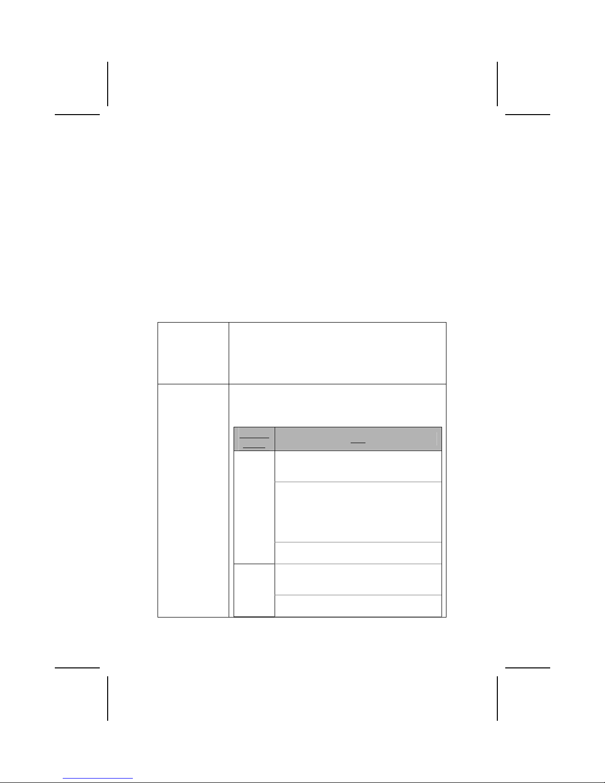
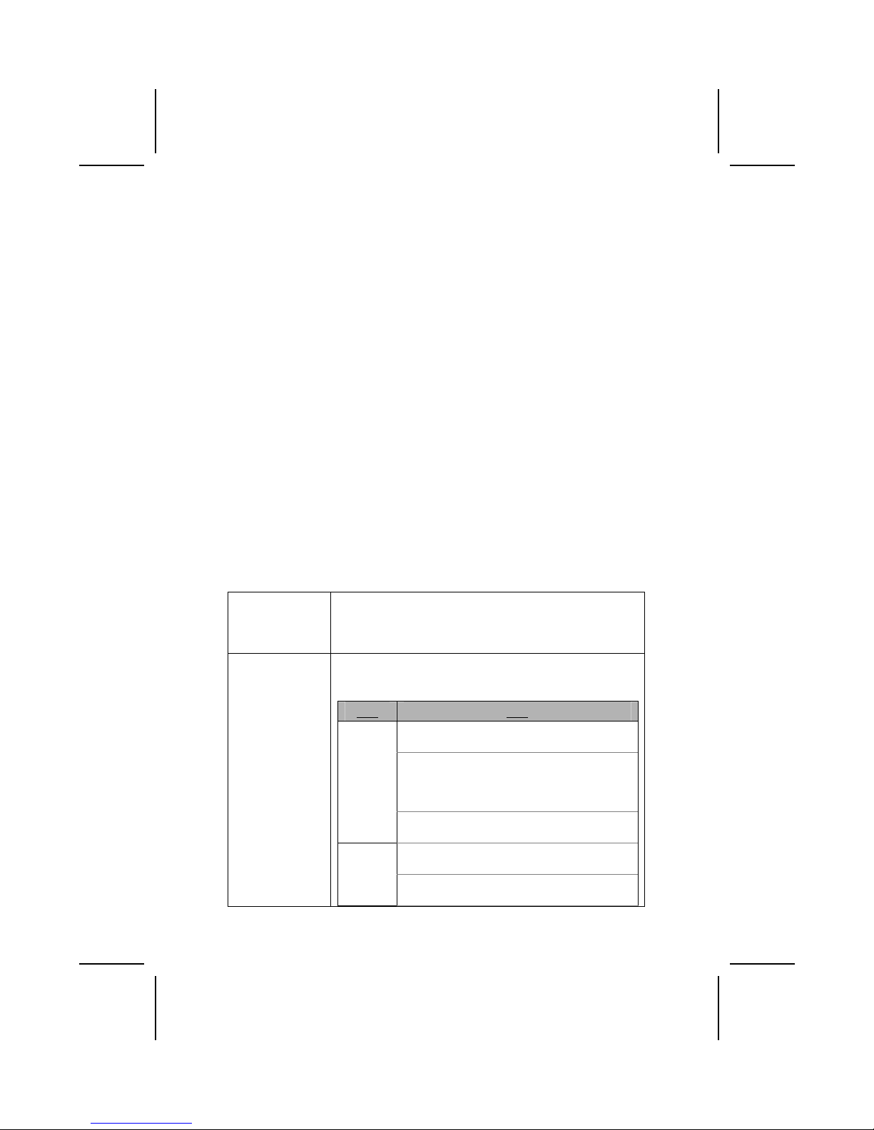
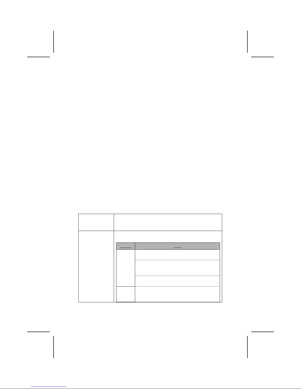
Caractéristiques
Processeur La carte mère utilise un Socket A AMD 462 broches
présentant les caractéristiques suivantes:
• Supporte un bus frontal (FSB) de 200/266/333 MHz
• Peut recevoir le Processeur AMD Athlon
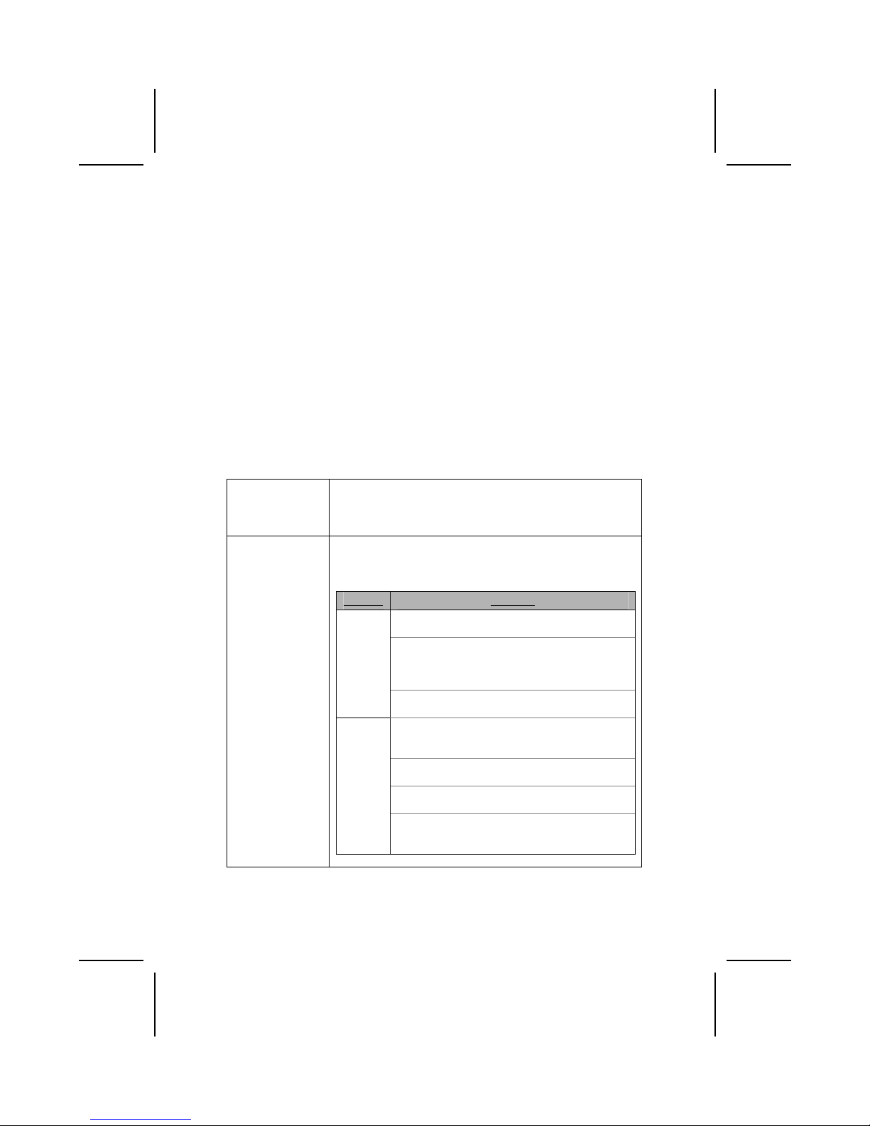
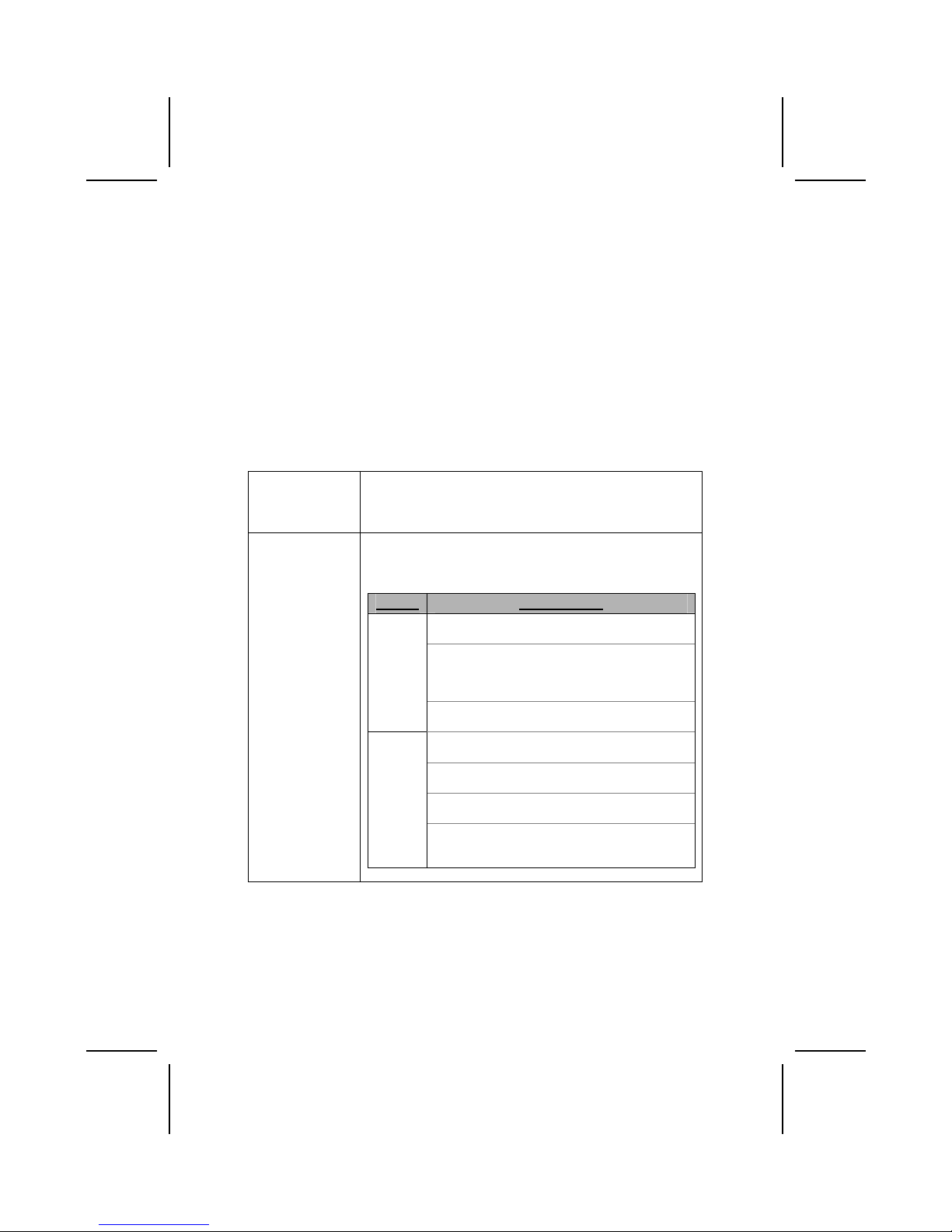
Chipset Le chipset sur cette carte mère comprend le chipset VT8378
(KM400) Northbridge combiné avec le chipset VT8235 ou
VT8237 Southbridge. Le tableau ci-dessous explique
brièvement certaines des caractéristiques avancées du
chipset.
Chipset Caractéristiques
Prend en charge DDR333, DDR266 et DDR200
(PC2700, PC2100 et PC1600 DDR SDRAM).
Contrôleur de Port Graphique Accéléré (AGP)
complet qui prend en charge les modes de
transfert 533 MHz 8x, 266 MHz 4x, et 133 MHz
2x pour signalisation Ad et SBA.
KM400
NB
Supporte une interface d’Hôte V-Link 66 MHz
avec une bande passante de pointe de
533Mo/sec.
Supporte une interface Client V-Link 66 MHz
avec une bande passante totale de 533 Mo/sec.
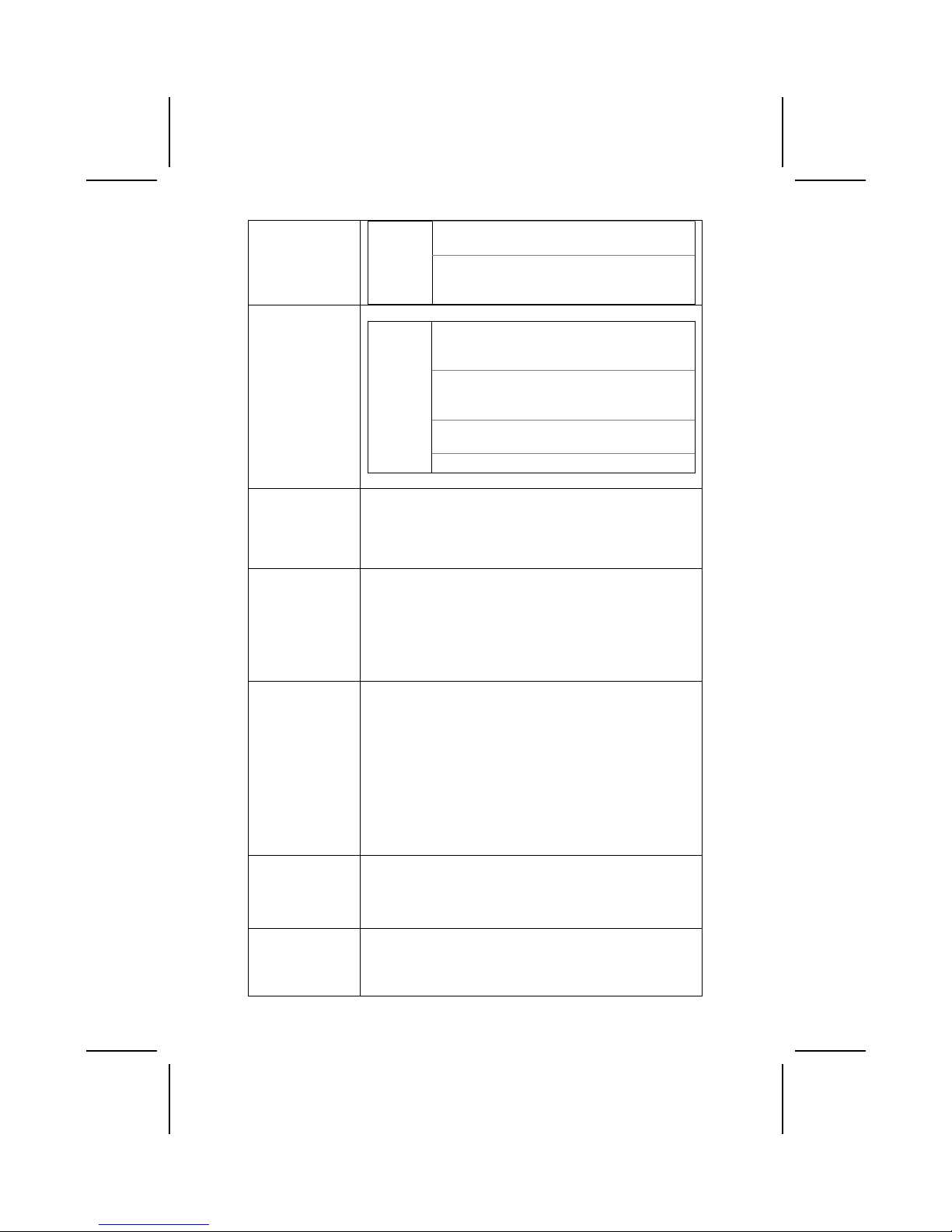
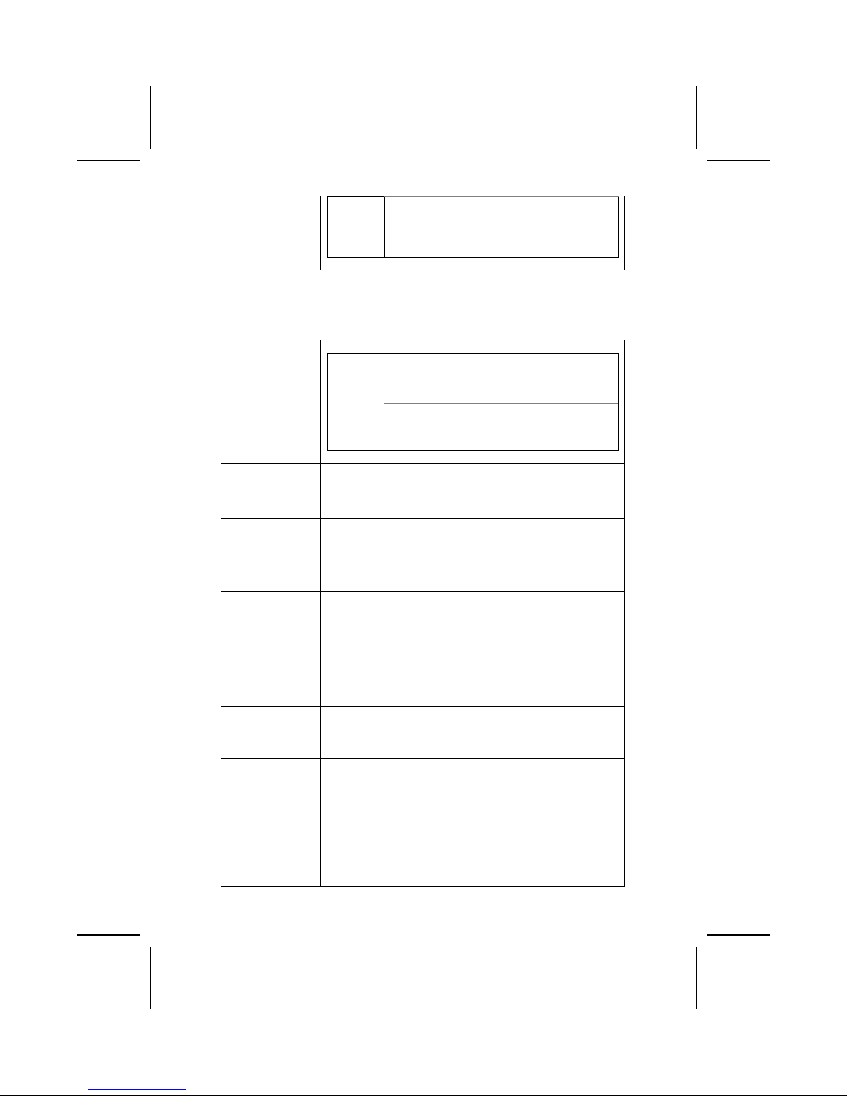
Contrôleur USB 2.0 intégré avec trois hubs
racine et six ports de fonction .
VT8235
SB
Contrôleur EIDE de mode maître UltraDMA33/66/100/133 de Canal double.
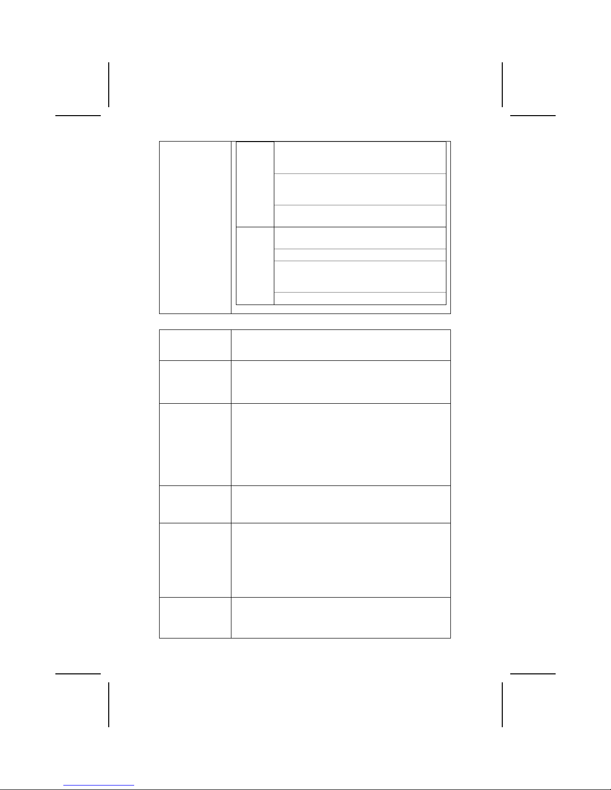
Page 4
iv
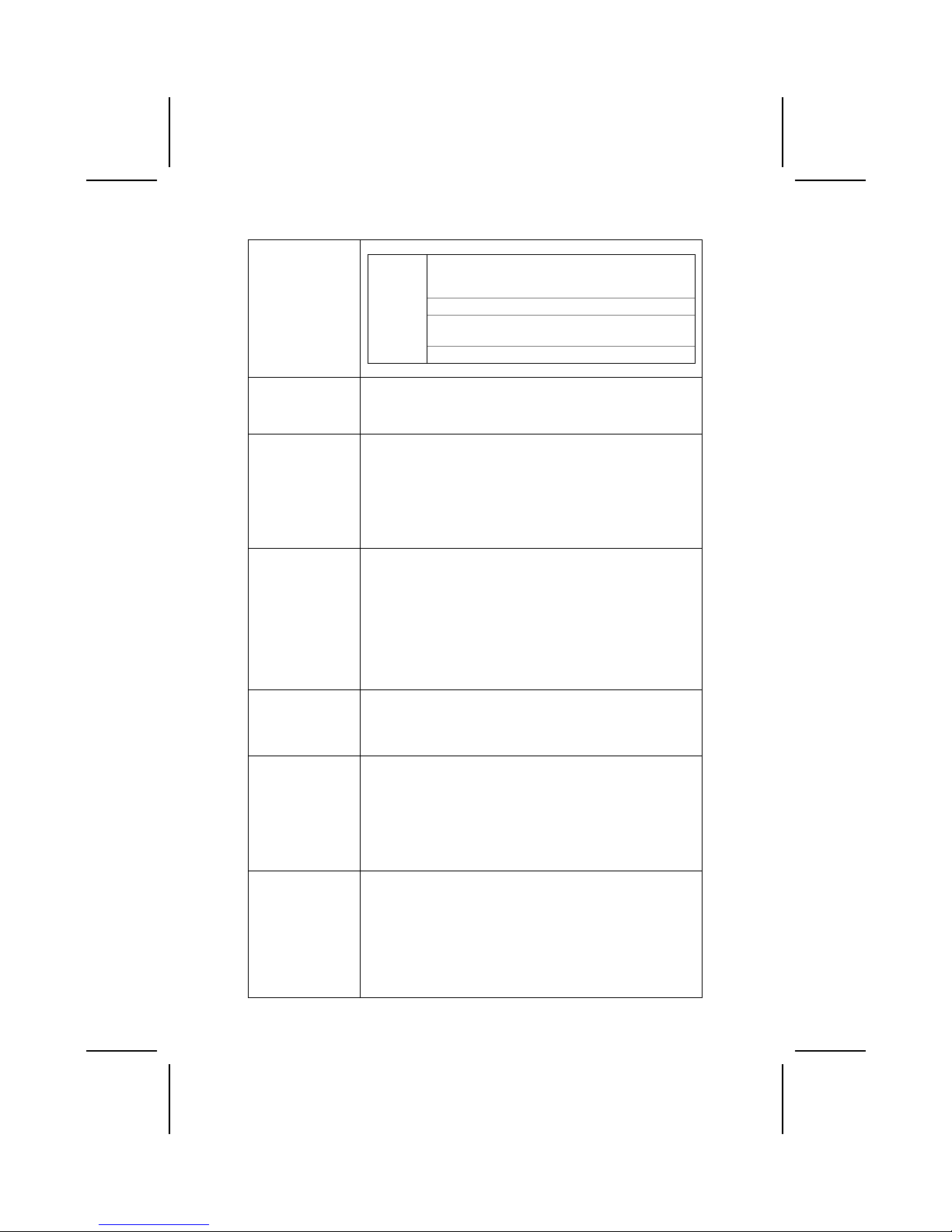
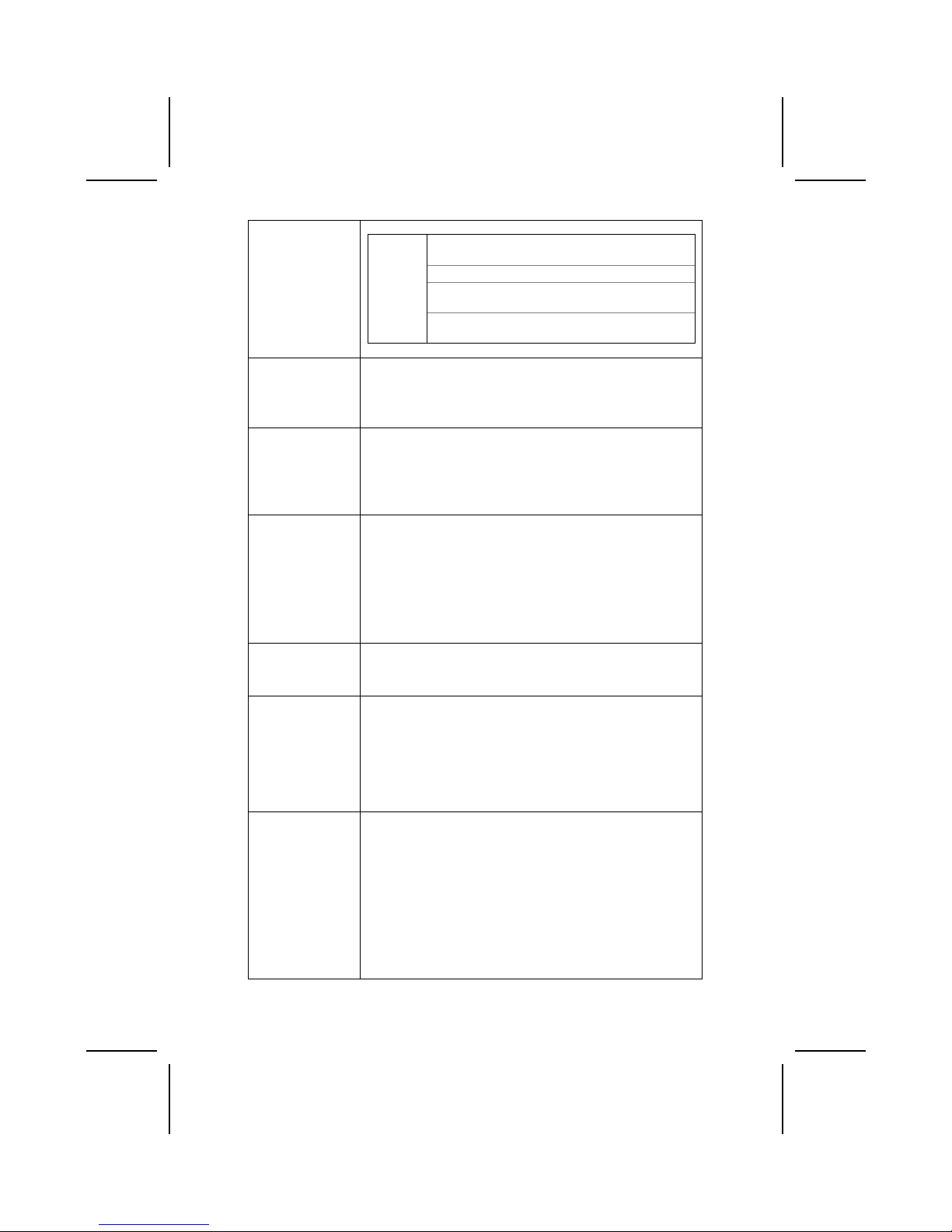
Supporte une interface Client V-Link 66 MHz
avec une bande passante totale de 1066
Mo/sec.
Contrôleur ATA/HDD Série de canal double.
Contrôleur USB 2.0 intégré avec quatre hubs
racine et huit ports de fonction.
VT8237
SB
Fonctionnement full et half duplex en 1/10/100
MHz.
Mémoire
• Support de module mémoire DDR SDRAM jusqu’à
200/266/333 MHz
• Peut recevoir deux logements sans mémoire tampon en
2.5V de 184 broches.
• Chaque logement supporte jusqu’à 1 Go avec une
capacité maximum totale de 2 Go.
VGA Cette carte mère comprend un logement AGP qui offre huit
fois la bande passante des spécifications AGP d'origine à 2.1
gigaoctets par seconde (Go/s). La technologie AGP offre une
connexion directe entre le sous-système graphique et le
processeur de sorte que les graphiques n’ont pas à entrer en
concurrence avec d’autres périphériques pour le temps
d’utilisation du processeur sur le bus PCI.
Codec Audio
AC’97
La ALC655 est conforme aux spécifications AC'97 2.3 et
supporte les extensions de CODEC multiples avec vitesses
d’échantillonnage variables indépendantes et effets 3D
intégrés. Elle intègre la technologie de convertisseur
propriétaire pour obtenir une SNR élevée, supérieure à 90 dB.
Le circuit de l’interface numérique fonctionne à partir d’une
alimentation en 5V/3.3V et supporte une fonction de sortie
SPDIF conforme AC'97 2.3 permettant une connexion facile à
partir du PC sur d’autres produits électroniques. Les fonctions
supplémentaires comprennent le support de quatre entrées
stéréo de niveau de ligne analogique.
Options
d’Extensions
Cette carte mère possède un logement AGP et trois logements
PCI 32 bits.
Elle supporte la maîtrise de bus Ultra DMA avec des vitesses
de transfert de 33/66/100/133 Mo/sec.
LAN Interne
(optionnel)
Le Realtek RTL8100C est un contrôleur Fast Ethernet
10/100Mbps a puce unique mini PCI d'un bon rapport qualité
prix hautement intégrée. Il prend en charge l’éveil à distance
(comprenant AMD Magic Packet
™
et Microsoft® Wake-up
frame) et la fonction de gestion ACPI (Configuration Avancée
et Interface d’Alimentation). Il fournit aussi un transfert de
données de maître bus
PCI avec une vitesse d’horloge PCI
de 16.75MHz-40MHz.
Page 5

v
1394a
(Optionnel)
• Contrôleur d’hôte VT6307 PCI 1394a intégré
• Conforme aux spécifications 1394 open HCI v1.0 et v1.1
• Supporte les provisions du standard IEEE 1394-1995
pour bus série de hautes performances et le supplément
P1394a 4.0
• Générateur CRC 32 bits CRC et vérificateur pour recevoir
et émettre des données
• Conforme aux spécifications PCI v2.2
• Support de maîtrise de bus de hautes performances
• Offre trois ports câbles entièrement compatibles 1394a à
100/200/400 Mbits par seconde
E/S Intégrées La carte mère possède un jeu complet de ports d’E/S et de
connecteurs:
• Deux ports PS/2 pour souris et clavier
• Un port série
• Un port VGA
• Un port parallèle
• Quatre ports USB
• Un port LAN (optionnel)
• Un port 1394a (optionnel)
• Prises audio pour microphone, ligne d’entrée et ligne de
sortie
Microprogramme
BIOS
Cette carte mère utilise Award BIOS qui permet aux
utilisateurs de configurer de nombreuses caractéristiques du
système comprenant les suivantes:
• Gestion d’alimentation
• Alarmes de réveil
• Paramètres de CPU
• Synchronisation de CPU et de mémoire
Le microprogramme peut aussi être utilisé pour définir les
paramètres pour les vitesses d’horloges de différents
processeurs.
Certaines spécifications matérielles et éléments de logiciels peuvent être
modifiés sans avertissement.
Page 6
vi
Checkliste
Vergleichen Sie den Packungsinhalt des Motherboards mit der folgenden
Checkliste:
Standard Items
• Ein Motherboard
• Ein Bandkabel für Diskettenlaufwerke
• Ein Bandkabel für IDE-Laufwerke
• Eine Auto-Installations-Support-CD
• I/O-Anschlussabdeckung für die Rückwand
• Ein SATA-Kabel
(mit eingeschlossen, wann Ihr Motherboard die SATA Überschrift stützt)
• Ein SATA-Netzkabel
(mit eingeschlossen, wann Ihr Motherboard die SATA Überschrift
stützt)
• Dieses Benutzerhandbuch
Features
Processor Das Motherboard verwendet einen AMD 462-Pin Sockel A mit
den folgenden Eigenschaften:
• Unterstützt 200/266/333 MHz Frontsidebus (FSB)
• Nimmt AMD Athlon-Prozessoren auf
Chipsatz Der Chipsatz dieses Motherboards verfügt über die VT8378
(KM400) Northbridge, die mit der VT8235 oder VT8237
Southbridge verbunden ist In der untenstehenden Tabelle werden
einige der fortschrittlichen Funktionen des Chipsatzes kurz
vorgestellt:
Chipsatz Funktionen
Unterstützt DDR333, DDR266 und DDR200
(PC2700, PC2100 und PC1600 DDR
SDRAM).
Volle Unterstützung für Accelerated Graphics
Port (AGP)-Controller (Unterstützung der
Transfermodu 533 MHz 8x, 266 MHz 4x und
133 MHz 2x für Ad und SBA-Signaling.
KM400
NB
Unterstützt 66MHz V-Link Host-Interface mit
einer maximalen Bandbreite von 533 MB/Sek.
Unterstützt 66MHz V-Link Client-Interface mit
einer totalen Bandbreite von 533 MB/Sek.
Onboard-USB 2.0-Controller mit vier Root
Hub und acht Port.
Dualkanal-UltraDMA-33/66/100/133 Master
Mode EIDE-Controller.
VT8235
SB
Unterstützt ACPI (Advanced Configuration
and Power Interface) und Legacy (APM)Energieverwaltung.
Page 7
vii
Unterstützt 16-Bit 66 MHz V-Link ClientInterface mit einer totalen Bandbreite von
1066 MB/Sek.
Dualkanal Serial ATA/HDD-Controller.
Onboard-USB 2.0-Controller mit vier Root
Hub und acht Port.
VT8237
SB
1/10/100 MHz Voll/Halbduplexbetrieb.
Speicher
• Unterstützt DDR bis zu 200/266/333MHz DDR SDRAM-
Speichermodul
• Nimmt zwei ungepufferte 2.5V 184-Pin Steckplätze auf
• Jeder Steckplatz unterstützt bis zu 1 GB mit einer
maximalen Gesamtkapazität von 2 GB
VGA Dieses Motherboard enthält einen AGP-Steckplatz, der die
achtfache Bandbreite der originalen AGP-Spezifikation
ermöglicht (bis zu 2.1 MB/Sek.). Die AGP-Technologie bietet
eine direkte Verbindung zwischen dem Grafik-Subsystem und
dem Prozessor, damit die Grafik nicht mit anderen Geräten auf
dem PCI-Bus um Prozessorzeit wetteifern muss.
AC’ 97 Audio
Codec
Der ALC655 ist kompatibel mit der AC´97 2.3-Spezifkation und
unterstützt mehrfache CODEC-Erweiterungen mit variablen,
unabhängigen Samplingraten und integrierten 3D-Effekten. Er
verfügt über eine gesetzlich geschützte Konverter-Technologie
zur Erreichung eines hohen SNR von mehr als 90 dB. Der
digitale Interface-Schaltschreis wird von einem 5 Volt /3.3 VoltNetzteil betrieben und unterstützt zum einfachen Anschluss an
einen PC oder andere elektronische Geräte eine SPDIF-OutFunktion. Weitere Funktionen beinhalten z.B. die Unterstützung
von vier analogen Line-Level-Eingängen.
Erweiterungsoptionen
Dieses Motherboard hat eine AGP-Steckplatz und drei 32-bit
PCI-Steckplätze.
Es unterstützt Ultra DMA Bus-Mastering mit Übertragungsraten
von 33/66/100/133 MB/s.
Integriertes
LAN (optional)
Der RTL8100C ist ein hochgradig integrierter und
kostengünstiger mini-PCI Single-Chip Fast Ethernet Controller
mit einer Geschwindigkeit von 10/100 MB/Sek. Er unterstützt
ferngesteuerte Weckfunktionen (einschließlich AMD Magic
Packet
™
und Microsoft® Wake-Up Frame) sowie die
Verwaltungsfunktion ACPI (Advanced Configuration Power
Interface). Außerdem bietet er PCI-Bus-Master-Datentransfer
mit einer PCI-Taktgeschwindigkeit von 16.75MHz-40MHz.
1394a (optional)
• VT6307 PCI 1394a integrierter Host-Controller
• Entspricht den 1394 Open HCI Spezifikationen v1.0 und
v1.1
• Unterstützt Bereitstellung von IEEE 1394-1995 Standard
Hochleistungs-Serial Bus und den P1394a Zusatz 4.0
• 32 bit CRC-Generator und Checker für Datenempfang und
Datenübertragung
• Entspricht PCI Spezifikation v2.2
• Unterstützung für Hochleistungs-Bus-Mastering
• Bietet drei vollständig 1394a kompatible Kabelanschlüsse
Page 8

viii
mit 100/200/400 Mbit pro Sekunde
Integrierte I/O Das Mainboard verfügt über einen kompletten Satz von I/O-
Schnittstellen und Anschlüssen:
• Zwei PS/2-Schnittstellen für Maus und Tastatur
• Eine serielle Schnittstelle
• Eine VGA-Schnittstelle
• Eine parallele Schnittstelle
• Vier USB-Schnittstellen
• Eine LAN-Schnittstelle (optional)
• Eine 1394a-Schnittstelle (optional)
• Audiobuchsen für Mikrofon, Line-in und Line-out
BIOS
Firmware
Dieses Mainboard setzt das Award BIOS ein, mit dem der
Anwender viele Systemeigenschaften selbst konfigurieren kann,
einschließlich der folgenden:
• Energieverwaltung
• Wake-up Alarm
• CPU-Parameter und Speichertiming
• CPU- und Speichertiming
Mit der Firmware können auch die Parameter für verschiedene
Prozessortaktgeschwindigkeiten eingestellt werden.
Bestimmte Hardwarespezifikationen und Teile der Softwareausstattung
können ohne weitere Ankündigung abgeändert werden.
Page 9
ix
Lista di controllo
Comparate il contenuto della confezione della scheda madre con la seguente
lista di controllo:
Articoli standard
• Una scheda madre
• Un cavo a nastro per il drive dischetti
• Un cavo a nastro IDE
• Un CD di supporto software auto-installante
• Una protezione per il pannello posteriore di I/O
• Un cavo SATA (incluso quando la vostra cartolina base sostiene l'intestazione di SATA)
• Un cavetto di alimentazione SATA
(incluso quando la vostra cartolina base sostiene
l'intestazione di SATA)
• Il manuale dell’utente
Caratteristiche
Processore La scheda madre è dotata di un socket A AMD a 462 pin che
presenta le seguenti caratteristiche:
• Supporta il bus di sistema (FSB) fino a 200/266/333 Mhz
• Possibilità di alloggiare le CPU Athlon AMD
Chipset Il chipset è composto dai chipset Northbrigde VT8378
(KM400) e Southbridge VT8235 o VT8237. La tabella
sottostante presenta una panoramica delle funzioni avanzate
del chipset:
Chipset Funzioni
Supporto DDR333, DDR266 e DDR200 (DDR
SDRAM PC2700, PC2100 e PC1600).
Controller AGP Full Featured (Accelerated
Graphics Port) in grado di supportare il bus dati
a 533 MHz 8x, 266 MHz 4x, and 133 MHz 2x
per il segnale Ad e SBA.
KM400
NB
Supporto interfaccia Host 66 MHz V-Link con
larghezza di banda sino a 533MB/sec.
Supporto interfaccia Client V-Link 66 MHz
interface con larghezza di banda totale pari a
533 MB/sec.
Controller USB 2.0 Integrated con tre porte hubs
e sei porte attive.
Controller EIDE master mode a doppio canale
UltraDMA-33/66/100/133.
VT8235
SB
Supporto sia degli standard ACPI (Advanced
Configuration and Power Interface) e APM per la
gestione del consume energetico.
Page 10
x
Supporto Dell’interfaccia Client V-Link a 16bit 66
MHz con larghezza di banda totale pari a 1066
MB/sec.
Controller Seriale a ATA/HDD a doppio canale.
Controller USB 2.0 Integrato con quattro hub
root e otto porte funzionanti.
VT8237
SB
Operazioni full e half duplex a 1/10/100 MHz.
Memory
• Supporto per i banchi SDRAM DDR a 200/266/333 MHz
• Presenza di due slot a 184 pin unbuffered 2.5V
• Ogni slot supporta sino ad un 1 GB con una capacità
massima pari a 2 GB
VGA Questa scheda madre possiede uno slot AGP in grado di
garantire una larghezza di banda 8 volte superiore rispetto a
quella prevista dalle specifiche dello standard AGP originale
che posso arrivare a 2.1 gigabytes al secondo (GB/s). Questa
tecnologia fornisce un collegamento diretto tra il sotto sistema
grafico ed il processore, evitando così che la scheda non
debba competere con altre per l’utilizzo del processore tramite
il bus PCI.
AC’ 97 Audio
Codec
Il codec ALC 655 è conforme alla specifiche AC 97 2.3 che
supporta estensioni CODEC multiple con capacità di
campionamento multiple e scalabili ed effetti 3D integrati. Ë
dotato di una tecnologia di conversione integrata per ottenere
un SNR di qualità elevata, maggiore di 90 dB. L’interfaccia
digitale è alimentata da un alimentatore a 3.3/5V e supporta un
SPDIF compatibile con le specifiche AC’97 2.3 con funzioni
che facilitano il collegamento di strumenti elettronici al PC.
Altre caratteristiche includono il supporto di quattro entrate
LINE STEREO analogiche
Expansion
Options
La scheda madre presenta tre slot PCI a 32 bit ed uno slot
AGP
Supporta la gestione di canali Ultra DMA con transfert rate pari
a 33/66/100/133 MB/sec.
Onboard LAN
(optional)
Il chip LAN Realtek RTL8100C é parte integrante dlla scheda
madre e fornisce un valido supporto come controller PCI
10/100 Mpbs Fast Ethernet ad un costo molto contenuto.
Supporta il Wake up remoto (incluso including AMD Magic
Packet
™
and Microsoft® Wake-up) e la gestione avanzata
ACPI (Advanced Configuration Power Interface). Permette
inoltre il trasferimento dati via bus master PCI ad una velocitá
di clock compresa tra
16.75MHz e 40MHz
1394a (optional)
• Controller VT6307 PCI 1394a integrato
• Conforme alle specifiche 1394 open HCI v1.0 e v1.1
• Supporto delle specifiche IEEE 1394-1995 per l’ottimento
di alte prestazioni ed inoltre per l’aggiornamento al
P1394a 4.0
• Generatore CRC a 32 bit e controllore per ricevere e
trasmettere dati
• Compatibile con le specifiche PCI v2.2
• Supporto per il bus principale ad alte prestazioni
Page 11

xi
• Presenti tre porte conformi allo standard 1394a capaci di
un trasferimento dati a 100/200/400 Mbit al secondo
I/O integrati La scheda madre è dotata di un set completo di connettori e
porte I/O:
• Due porte PS/2 per mouse e tastiera
• Una porta seriale
• Una porta VGA
• Una porta parallela
• Quattro porte USB
• Una porta LAN (opzionale)
• Una porta 1394a (opzionale)
• Jack audio per microfono e connettori ingresso/uscita
Line
BIOS Questa scheda madre utilizza il BIOS Award che permette
all’utente di configurare numerose caratteristiche del sistema
tra cui le seguenti:
• Risparmio energetico
• Segnali Wake Up
• Parametri della CPU e sincronizzazione memoria
• Timing della memoria e della CPU
E’ possibile inoltre impostare i parametri di velocità del clock
del processore su diversi valori.
Alcune specifiche hardware ed elementi software sono soggetti a variazioni
senza preavviso.
Page 12
xii
Lista de Verificación
Compare los contenidos del paquete de la placa principal con la sigte. lista:
Ítems Estándares
• Una placa principal
• Un cable cinta del lector de diskette
• Un cable cinta de la unidad IDE
• Un CD de soporte en software de autoinstalación
• Un protector del panel I/O trasero
• Un cable SATA
(incluido cuando su placa base apoya el jefe de SATA)
• Un cable de suministro SATA (incluido cuando su placa base apoya el jefe de SATA)
• Este manual del usuario
Características
Procesador El panel principal usa un AMD 462-pin Enchufe A que tiene
las siguientes características:
• Permite 200/266/333 MHz bus de lado frontal (FSB)
• Adecua procesadores AMD Athlon
Chipset El chipset en esta placa principal incluye la VT8378 (KM400)
Northbridge combinado con el chipset VT8235 o VT8237
Southbridge. La tabla abajo explica algunas de las características
avanzadas del chipset:
Chipset Características
Soporta DDR333, DDR266 y DDR200 (PC2700,
PC2100 y PC1600 DDR SDRAM).
Controlador de Puerto de Gráficas Accelerado
(AGP) caracterizado que soporta los modos de
transferencias de 533 MHz 8x, 266 MHz 4x, y
133 MHz 2x para la señalización Ad y SBA.
KM400
NB
Soporta la interfaz 66 MHz V-Link Host con
ancha de banda pico de 533MB/seg.
Soporta la interfaz 66 MHz V-Link Client con la
ancha de banda total de 533 MB/seg.
Controlador USB 2.0 Integrado con tres hubs de
raíz y seis puertos de función.
Controlador EIDE del modo máster UltraDMA33/66/100/133 de canal dual.
VT8235
SB
Soporta ambos ACPI (Configuración Avanzada
e Interfaz de Suministro) y administración de
suministro de legado (APM).
Page 13
xiii
Soporta la interfaz 16-bit 66 MHz V-Link Client
con ancha de banda total de 1066 MB/seg.
Controlador ATA/HDD de serie de canal dual.
Controlador USB 2.0 integrado con cuatro hubs
de raíz y ocho puertos de función.
VT8237
SB
Operación de duplex medio y completo de
1/10/100 MHz.
Memoria
• Permite DDR hasta 200/266/333MHz DDR módulo de
memoria SDRAM
• Adecua dos ranuras no reservadas 2.5V 184-pin
• Cada ranura permite hasta 1 GB con una capacidad
máxima total de 2 GB
VGA Esta placa principal incluye una ranura AGP que provee ocho
tiempos de amplitud de la especificación original AGP a 2.1
gigabytes por segundo (GB/s). La tecnología AGP provee una
conexión directa entre el sub-sistema de gráficos y el procesador
para que los gráficos no tengan que rivalizar por el tiempo del
procesador con otros componentes en la Ruta PCI.
El Codec AC’ 97
Audio
El ALC655 se conforma con la especificación AC'97 2.3 y
soporta múltiples extensiones CODEC con índice de muestreo
variable y efectos 3D incorporados. Incorpora la tecnología de
conversor propietaria para lograr un SNR alto, mayor que 90
dB. El circuito de interfaz digital opera de un suministro de
5V/3.3V y soporta una función de salida SPDIF conforme con
AC'97 2.3 que permite la conexión fácil del PC a otros
productos electrónicos. Otras características incluyen soporte
para cuatro entradas estereofónicas a nivel de línea analógica.
Opciones de
Expansión
Esta placa principal tiene un AGP y tres ranuras PCI 32-bit.
Permite bus de control Ultra DMA con valor de transferencia
de 33/66/100/133 MB/por segundo.
LAN
Incorporada
(opcional)
The Realtek RTL8100C es un controlador Fast Ethernet de
mini PCI single-chip 10/100 Mpbs altamente integrado y
eficiente a costo. Soporta despertador remoto (incluye cuadro
AMD Magic Packet
™
y Microsoft® Wake-up) y la función de
administración ACPI (Interfaz de Suministro de Configuración
Avanzada/Advanced Configuration Power Interface). También
provee transferencia de datos de master bus
PCI con una
velocidad de reloj de 16.75MHz-40MHz.
1394a (opcional)
• Controlador de interfaz VT6307 PCI 1394a incorporado
• Adaptable con 1394 abierto, especificaciones HCI v1.0 y
v1.1
• Permite abastecimiento de IEEE 1394-1995 convencional
para bus de serie de alto rendimiento y P1394a suplemento 4.0
• Generador CRC 32 bit y verificador para recibir y trans-
mitir datos
• Adaptable con especificación PCI v2.2
• Apoyo de bus de control de alto rendimiento
• Provee tres puertos de cable totalmente adaptables
1394a en 100/200/400 Mbit por segundo
Page 14

xiv
I/O Integrado
El tablero principal tiene un set completo de puertos de
Entrada/Salida y conectores:
• Dos puertos PS/2 para ratón y teclado
• Un puerto de serie
• Un puerto VGA
• Un puerto paralelo
• Cuatro puertos USB
• Un puerto LAN (opcional)
• Un puerto 1394a (opcional)
• Enchufes de audio para micrófono, línea de entrada y
línea de salida
BIOS Firmware Este panel principal usa el Award BIOS que posibilita a los
usuarios configurar muchas características de sistema
incluidas las siguientes:
• Administración de potencia
• Alarmas despertadoras
• Parámetros y memoria de temporizador CPU
• Memoria de temporizador CPU
El firmware puede también ser usado para ajustar parámetros
para velocidades diferentes de procesador de reloj.
Algunas especificaciones de hardware e ítems de software son sujetos a
cambio sin previo aviso.
Page 15
xv
チェックリスト
下記のチェックリストに列挙されている製品が同封されているかを確認して
ください。
標準同封アイテム
• メインボード 1 枚
• ディスクドライブ用リボンケーブル 1 個
• IDE ドライブ用リボンケーブル 1 個
• 自動インストール機能対応ソフトウェア CD 1 枚
• リアパネル I/O シールド 1 個
• SATA コードが 1 本と
(あなたのマザーボードが SATA ヘッダーを支える時含まれた)
• SATA 電源線が 1 本と
(あなたのマザーボードが SATA ヘッダーを支える時含まれた)
• ユーザーマニュアル
製品特徴
プロセッサ 当マザーボードに搭載されている ADM 462 ピンソケットは、
次
の特徴があります:
• 200/266/333 MHzフロントサイドバス(FSB)をサポー
トします
• AMD Athlon プロセッサをサポートします
チップセット 当マザーボードに搭載されているチップセットは、 VT8378
(KM400) Northbridge と、 VT8235 あるいは VT8237
Southbridge の何れかとを備え 、下表に示される先進な機能
をお届けします。
チップセ
ット名
機能
DDR333 と DDR266 と DDR200 をサポート
(PC2700
と PC2100 と PC1600 との DDR SDRAM) 。
全機能の AGP( Accelerated Graphics Port)コ
ントローラーを搭載し、 533 MHz 8x や
266MHz
4x や 133 MHz 2x の転送モードでの Ad と
SBA
との信号転送に完全対応。
KM400 NB
66 MHz V-Link ホストインターフェースをサポ
ートし、ビーク帯域幅 533MB/秒。
66 MHz V-Link クライアントインターフェース
をサポートし、トータル帯域幅 533MB/秒可
能。
VT8235
SB
搭載した USB 2.0 コントローラーで、3 つのル
ートハブと 6 つのポートを提供。
Page 16
xvi
二重チャネル UltraDMA-33/66/100/133 マス
ターモードの EIDE コントローラーを搭載。
ACPI (Advanced Configuration and Power
Interface) と従来の (APM) 電源管理機能をサ
ポート。
16 ビットの 66 MHz V-Link クライアントイン
ターフェースをサポートし、トータル帯域幅
1066 MB/秒まで可能。
二重チャネルシリアル ATA/HDD コントローラ
ー
を搭載。
内蔵している USB 2.0 コントローラーで、4 つ
のルートハブと 8 つのポートを提供。
VT8237
SB
1/10/100 MHz の全/半二重動作が可能。
メモリー
• 200/266/333MHz DDR SDRAM までの DDR メモリモジュール
に対応
• 2 つの非バッファー2.5V 184 ピン仕様のスロットを収納
• 各スロットが 1 GB まで対応し、トータルでメモリを 2
GB までサポートします
VGA 本マザーボードは、従来の AGP 仕様の 8 倍、2.1GB/秒に相当す
る帯域幅を提供することができる AGP スロットが搭載されてい
ます。AGP 技術は、グラフィックサブシステムとプロセッサと
の間での直接通信を実現することにより、グラフィックサブシ
ステムが PCI バスでその他のデバイスと競合する問題ことを解
消しま
す。
AC’ 97 オーディ
オコーデック
ALC655 オーディオコーデックは AC’ 97 2.3 仕様に準拠した
もので、様様な CODEC 拡張機能をサポートしながら、独立の
可変サンプリング率と共に 3D 効果機能をも内蔵しておりま
す。独自の変換技術を取り入れることにより、90dB 超の高い
SNR を
実現しました。そのデジタル式インターフェース回路は、
5V/3V 電源サプライで動作し、かつ AC’ 97 2.3 仕様に準拠
した
SPDIF 出力機能をサポートしておりますので、他の電子製品を
容易にシステムに接続することができます。さらに、アナロ
グ式レインレベルステレオ入力を 4 つまでサポートします。
拡張オプション 当マザーボードには 1 つの AGP スロットと 3 つの 32 ビット
PCI スロットが搭載されています。
さらに、33/66/100/133 MB/秒の転送速度の Ultra DMA バスマ
スタリングをサポートします。
オンボード LAN
機能 (オプショ
ン)
The Realtek RTL8100C は、高度に統合され、優れた性能価
格比を持つ小型 PCI シングルチップ 10/100 Mpbs 高速イー
サーネットコントローラーであります。遠隔喚起機能(即ち、
AMD Magic Packet
™
や Microsoft® Wake-up フレームなど)
Page 17

xvii
と ACPI (Advanced Configuration Power Interface) 管理機
能をサポートします。さらに、PCI クロックスピードが
16.75
MHz-40MHz である
PCI バスマスタデータ転送をサポートし
ます。
1394a (オプショ
ン)
• VT6307 PCI 1394a 統合ホストコントローラ
• 1394 オープン HCI 仕様 v1.0 と v1.1 に対応
• 高性能シリアルバス及び P1394a 補足 4.0 のための IEEE
1394-1995 標準に対応
• データ送受信用の 32 ビット CRC ジェネレータとチェッカ
ー
• PCI 仕様 v2.2 対応
• 高性能バスマスタリング対応
• 100/200/400 Mbit/秒の 1394a 完全対応ケーブルポート 3
つを搭載
統合された入出力
ポート
このメインボードにはフルーセットの I/O ポートおよびコネ
クタが搭載しています。
• 2 つのマウスおよびキーボード向け PS/2 ポート
• 1 つのシリアルポート
• 1 つの VGA ポート
• 1 つのパラレルポート
• 4 つの USB ポート
• 1つの LAN ポート (オプション)
• 1 つの 1394a ポート(オプション)
• マイクロフォンやラインイン、ラインアウト向けのオーデ
ィオジャック
BIOS
ファームウェア
本メインボードは次のシステム機能を含めた設定をすること
ができる Award BIOS を採用しています:
• 電源管理
• Wake-up 警告
• CPU パラメータ
• CPU およびメモリのタイミング
その他に、各種プロセッサクロック速度のパラメータを設定
することができます。
一部のハードウェア仕様及びソフトウェアアイテムは予告なく変更されるこ
とがあります。
Page 18
xviii
품목 목록
다음 품목들이 메인보드 패키지에 모두 포함되어 있는지 확인해 보십시오:
표준 품목
• 메인 보드 1 개
• 디스켓 드라이브 리본 케이블 1 개
• IDE 드라이브 리본 케이블 1 개
• 자동 설치 소프트웨어 지원 CD 1 개
• 뒷패널 I/O 실드 1 개
• SATA 케이블 1 개
(너의 어미판이 SATA 우두머리를 지원할 때 포함하는)
• SATA 전원 케이블 1 개 (너의 어미판이 SATA 우두머리를 지원할 때 포함하는)
• 본 사용자 설명서
기능
프로세서 본 마더보드는 AMD 462 핀 소켓 A 를 사용하며 다음과 같은
특징을 지닌다:
• 200/266/333 MHz frontside bus (FSB) 지원
• AMD Athlon 프로세서 사용
칩셋 본 마더보드에 있는 칩셋은 VT8378 (KM400) Northbridge
와 VT8235 또는 VT8237 Southbridge 칩셋을 조합한다.
아래 표는 칩셋의 고급 기능을 간단히 설명한다.
칩셋 특징
DDR333, DDR266 및 DDR200 (PC2700,
PC2100 및 PC1600 DDR SDRAM) 지원.
Ad 와 SBA 시그널링을 위해 533 MHz 8x,
266 MHz 4x, 및 133 MHz 2x 전송 모드를
지원하는 고급의 Accelerated Graphics Port
(AGP) 컨트롤러.
KM400
NB
최고 대역폭 533MB/sec 의 66 MHz V-Link
호스트 인터페이스 지원.
총 대역폭 533 MB/sec 의 66 MHz V-Link
클라이언트 인터페이스 지원
VT8235
SB
3 개의 루트 허브와 6 개의 기능 포트를 지닌
통합 USB 2.0 컨트롤러.
Page 19
xix
듀얼 채널 UltraDMA-33/66/100/133 마스터
모드 EIDE 컨트롤러.
ACPI (Advanced Configuration and Power
Interface) 와 legacy (APM) 전원 관리 지원.
VT8237
SB
총 대역폭 1066 MB/sec 의 16 비트 66 MHz
V-Link 클라이언트 인터페이스 지원.
듀얼 채널 시리얼 ATA/HDD 컨트롤러.
4 개의 루트 허브와 8 개의 기능 포트가 있는
통합 USB 2.0 컨트롤러.
1/10/100 MHz full / half duplex 오퍼레이션.
메모리
• DDR 을 최대 200/266/333MHz DDR SDRAM 메모리
모듈 지원
• 2 개의 unbuffered 2.5V 184 핀 슬롯 사용
• 총 최대 용량은 2GB 이며, 각 슬롯은 최대 1 GB 를 지원
VGA 본 마더보드는 기존 AGP 사양의 8 배의 대역폭을 매초간 2.1
기가바이트 (GB/s) 을 제공하는 AGP 슬롯을 사용한다. AGP
기술은 그래픽 하부 시스템과 프로세서를 직접 연결하여
그래픽이 PCI 버스 상에 있는 다른 장치와 프로세서 시간을
다툴 필요가 없다..
AC’ 97 오디오
코덱
ALC655 는 AC'97 2.3 사양에 부합되며
독립적인
다양한
샘플링 속도와 내장 3D 효과를 지닌 다양한 코덱 확장을
지원한다. 90 dB 이상의 고품질의 SNR 을 위해 적합한 컨버터
기술을 사용하
였다. 디지털 인터페이스 회로는 5V/3.3V 파워 써플라이로 작동
되며, AC'97 2.3 부합 SPDIF 출력 기능을 지원하여 PC 와 다른
전기 제품의 연결을 용이하게 한다. 그 밖에도 4 개의 아날로그
라인 레벨 스테레오 입력을 지원한다.
확장 옵션 본 마더보드는 AGP 슬롯 1 개와 32 비트 PCI 슬롯 3 개가 있다.
이것은 전송 속도 33/66/100/133 MB/sec 의 Ultra DMA bus
mastering 을 지원한다.
보드 내장 LAN
(선택 사항)
Realtek RTL8100C 는 고도로 통합되고 비용 효율적인 미니
PCI 싱글 칩 10/100 Mpbs 패스트 이더넷 컨트롤러이다. 이것은
원격 wake-up (AMD Magic Packet
™
및 Microsoft® Wake-up
프레임 포함) 및 ACPI (Advanced Configuration Power Interface) 관리 기능을 지원하며,
16.75MHz-40MHz 의 PCI 클록
속도의
PCI 버스 마스터 데이터 전송을 제공한다.
1394a (선택 사항)
• VT6307 PCI 1394a 통합 호스트 컨트롤러
• 1394 open HCI 사양 v1.0 및 v1.1 호환
• 고 성능 시리얼 버스를 위한 IEEE 1394-1995 표준 규정 및
Page 20

xx
P1394a 증보 4.0 부합
• 데이터 수신 및 송신을 위한 32 bit CRC 제너레이터 및
검사기
• PCI 사양 v2.2 호환
• 고 성능의 bus mastering 지원
• 매초 100/200/400 Mbit 의 3 개의 1394a 호환 케이블 포트
제공
통합 I/O 본 마더보드는 풀 세트의 I/O 포트 및 커넥터가 있다:
• 마우스와 키보드용 PS/2 포트 2 개
• 시리얼 포트 1 개
• VGA 포트 1 개
• 패러럴 포트 1 개
• USB 포트 4 개
• LAN 포트 1 개 (선택 사항)
• 1394a 포트 1 개 (선택 사항)
• 마이크 용 오디오 잭, 라인 입력과 라인 출력
BIOS
펌웨어
본 마더보드는 Award BIOS 를 사용하여 사용자는 다음과 같은
시스템 기능을 구성할 수 있다:
• 전원 관리
• 기상 알람
• CPU 파라미터
• CPU 및 메모리 타이밍
펌웨어는 다른 프로세서 클럭 속도의 파라미터를 설정하는데도
사용될 수 있다.
하드웨어 사양 및 소프트웨어 아이템은 사전 통보 없이 변경될 수 있음.
Page 21
xxi
檢查表
請依下列檢查表,核對主機板包裝之內容:
標準項目
• 主機板一片
• 磁碟機排線一條
• IDE 磁碟機排線一條
• 自動安裝 CD 一片
• 後控制面板輸出入(I/O)擋板一片
• 1 條 SATA 連接線
(當你的主機板支援 SATA 排針時才會附)
• 1 條 SATA 電源線 (當你的主機板支援 SATA 排針時才會附)
• 本使用手冊
性能
中央處理器 本主機板採用了具有下列功能之 AMD 462 針 Socket A:
• 支援高達 200/266/333 MHz 之前置匯流排 (FSB)
• 支援 AMD Athlon 處理器
晶片組 本主機板係以 VT8378 (KM400) 北橋晶片組搭配 VT8235 或
VT8237 南橋晶片組,具有如下表所述之先進晶片組功能:
晶片組 功能
支援 DDR333, DDR266 及 DDR200 (PC2700,PC2100
及 PC1600 DDR SDRAM) 。
提供全功能的繪圖加速埠 (AGP)控制器,能夠支
援 533 MHz 8x、266 MHz 4x、及 133 MHz 2x 傳輸
模式的 Ad 及 SBA 信號傳送。
KM400
NB
支援 66 MHz V-Link 主機介面,最大頻寬可達
533MB/秒。
VT8235
SB
支援 66 MHz V-Link 客戶介面,總頻寬可達 533
MB/
秒。
Page 22
xxii
內建 USB 2.0 控制器,提供 3 個集線器及 6 個連
接
埠。
具有雙通道 UltraDMA-33/66/100/133 主控模式
EIDE
控制器。
支援 ACPI (Advanced Configuration and Power Interface) 及舊版的(APM)電源管理功能。
支援 16-bit 66 MHz V-Link 客戶介面,總頻寬高達
1066 MB/秒。
具有雙通道串列 ATA/HDD 控制器。
內建 USB 2.0 控制器,提供 4 個集線器及 8 個連
接
埠。
VT8237
SB
具有 1/10/100 MHz 全/半雙工功能。
記憶體
• 支援 DDR 高達 200/266/333MHz 之 DDR 型 SDRAM 記憶體
• 配備有 2 無緩衝 2.5V184 針插槽
• 各插槽支援 1GB,共可支援 2GB 之記憶體
VGA 本主機板配備有一個 AGP 插槽,能夠支援為舊型 AGP 規格 8 倍
之頻寬,相當於 2.1GB/秒。AGP 技術能使繪圖子系統與中央處理
器直接連接,藉此繪圖子系統將無需與其他 PCI 插槽設備在爭取
處理器資源上發生衝突。
AC’ 97 音訊編解
碼器
配備之 ALC655 音效解碼/編碼器採用了 AC’ 97 2.3 規格,且支
援多 CODEC 擴充子集,具有獨立的可變取樣率及內建的 3D 效
果功能。本編解碼器具有一專屬的轉換技術,能夠得到更高的
SNR(實際高達 90dB)。該數位介面電路可使用 5V/3.3V 的電源,
支援符合 AC’97 2.3 規格的 SPDIF 輸出功能,能夠使其他電子
產
品更容易地與連接電腦連接。再者,也提供 4 種類比線級立體
音效輸入。
擴充選項 本主機板 提供有 1 個 AGP 插槽及 3 個 32-位元 PCI 插槽。
此外,也支援 Ultra DMA 匯流排主控功能,可提供 33/66/100/
133 MB/sec 之傳輸速率。
機載區域網路功能
(選項)
Realtek RTL8100C 為高度整合且具有高經濟效益的迷你 PCI 單
晶片型 10/100 Mpbs 高速乙太網路控制器,能夠支援遠距喚醒
功能 (包括 AMD Magic Packet
及 Microsoft® Wake-up 框架) 及
ACPI (Advanced Configuration Power Interface) 管理功能,
並且也能以
16.75MHz-40MHz 的 PCI 時脈速率進行 PCI 匯流
排
主控的資料傳輸。
1394a (選項)
• VT6307 PCI 1394a 整合型主控控制器
• 符合 1394 開放式 HCI 規格 v1.0 及 v1.1
• 支援 高效能串列匯流排用 IEEE 1394-1995 規格及 P1394a 增
列規格 4.0
Page 23

xxiii
• 配備有 32 位元 CRC 產生器及檢測器,用以收發資料
• PCI 規格 v2.2 相容
• 支援高效能匯流排主控功能
• 配備有 3 個 1394a 完全相容連線埠,提供每秒 100/200/400
M 位元之傳輸效率
已整合的輸出入功能 本主機板完整地支援各種輸出入及連接器:
• 2 個 PS/2 埠,分供滑鼠及鍵盤連接
• 1 個串列埠
• 1個VGA埠
• 1 個平行埠
• 4個USB埠
• 1個LAN埠(選項)
• 1 個 1394a 埠(選項)
• 麥克風、line-in 及 line-out 音效端
BIOS 韌體 本主機板使用了 Award BIOS ,使用者可藉此對包括下列之系統
功能進行設定:
• 電源管理功能
• 喚醒警示功能
• CPU 參數
• CPU 及記憶體時序
本 BIOS 也可用以設定各種有關處理器時脈的參數。
有些硬體規格以及軟體物件將視狀況適當調整,不予另行通知。
Page 24
xxiv
校验表
将本主板的组件内容与以下校验表进行对照:
标准组件
• 一只主板
• 一条磁盘驱动器带状电缆
• 一条 IDE 驱动器带状电缆
• 一张自动安装软件支持光盘
• 一个后面板 I/O 防护罩
• 一 条 SATA 电缆
(包括当你的主板支持 SATA 头球)
• 一 条 SATA 电源线
(包括当你的主板支持 SATA 头球)
• 本用户手册
特性
处理器 主板使用一个 AMD 462-pin Socket A 插座,此插座具有以下
特点:
• 支持 200/266/333 MHz 前端总线 (FSB)
• 支持 AMD Athlon 处理器
芯片组 此主板含有 VT8378 (KM400) 北桥芯片组和 VT8235 或 VT8237
南桥芯片组。下表中简要介绍了芯片组的先进功能。
芯片组 功能
KM400
NB
支 持 DDR333 、 DDR266 和 DDR200 (PC2700,
PC2100 and PC1600 DDR SDRAM)。。
Page 25
xxv
完整的加速图形端口 (AGP) 控制器,支持 533
MHz 8x、266 MHz 4x 和 133 MHz 2x 传输模式。
NB
支持峰值带宽为 533MB/sec 的 66MHz V-Link
Host 接口。
支持总带宽为 533MB/sec 的 66MHz V-Link 客户
接口。
集成 USB 2.0 控制器,带有 3 个 Root Hub 和
6 个功能端口。
双通道 UltraDMA-33/66/100/133 主控模式 EIDE
控制器。
VT8235
SB
支持 ACPI (高级配置 电源 接口) 和传统 (APM)
电源管理。
支持总带宽为 533MB/sec 的 16 位 66MHz VLink 客户接口。
双通道串行 ATA/HDD 控制器。
集成 USB 2.0 控制器,带有 4 个 Root Hub 和
8 个功能端口。
VT8237
SB
1/10/100 MHz 全双工和半双工操作。
内存
• 支持 200/266/333 MHz DDR SDRAM 内存条
• 提供 2 个非缓冲 2.5V 184 pin 插槽
• 每个插槽支持 1 GB,总共最大可支持 2 GB
VGA 此主板含有一个 AGP 插槽,可提供普通 AGP 规格 8-倍的带
宽,可达 2.1 GB/s。AGP 技术能提供图像子系统和处理器之间
的直接连接,这样图像就不需要与 PCI 总线上的其它设备争用
处理器时间。
AC’ 97 音频编码器 ALC655 符合 AC'97 2.3 规格,支持多个具有独立可调采样速
率和内建 3D 音效的编解码器。它与专有的转换器技术相
结合,能够获得大于 90 dB 的 SNR(信噪比)。数字接口电路
可以在 5V/3.3V 电源下工作,并支持符合 AC'97 2.3 规格的
SPDIF 输出功能,此功能可以方便的将 PC 与其它电子产品连
接在一起。其它功能包括支持 4 路模拟线路级立体声输入。
扩展 选项 此主板含有 1 个 AGP 插槽和 3-个 32 位 PCI 插槽。
它支 持 Ultra DMA 总 线控制,传输速率可达 33/66/100/133
MB/sec。
Onboard LAN(可
选)
RTL8100C 是一种高度集成的低成本迷你 PCI 单芯片 10/100
Mpbs 快速以太网控制器。它支持远程唤醒(包括 AMD Magic
Packet
™
和 Microsoft® 唤醒帧)和 ACPI(高级配置电源接
口)管理功能。它还提供 PCI 时钟速度为 16.75MHz-40MHz-的
PCI 总线主控数据传输。
1394a(可选)
• VT6307 PCI 1394a 集成主控制器
• 兼容 1394 open HCI v1.0 和 v1.1 规格
• 支持 IEEE 1394-1995 标准中对高性能串行总线的规定和
Page 26
xxvi
P1394a 附录 4.0
• 32 位 CRC 发生器和检查器用于接收和传输数据
• 兼容 PCI v2.2 规格
• 支持高性能总线主控
• 提供 3 个 1394a 全兼容的电缆端口,传输速率达
100/200/400 Mbit/秒
集成 I/O 此主板具有完整的 I/O 端口和插孔:
• 2 个用于连接鼠标和键盘的 PS/2 端口
• 1 个串口
• 1 个 VGA 端口
• 1 个并口
• 4 个 USB 端口
• 1 个 LAN 端口(可选)
• 1 个 1394a 端口(可选)
• 麦克风、线入和线出声音插孔
BIOS 此主板使用 Award BIOS,可以让用户自己配置以下系统功能:
• 电源管理
• 唤醒报警
• CPU 参数
• CPU 和记忆定时
还可用于设置不同处理器时钟速度的参数。
部分硬件规格和软件项目若有更改恕不另行通知。
Page 27

xxvii
T
T
AABBLLEE OOFF
C
C
OONNTTEENNTTS
S
Preface i
Features and Packing List Translations iii
CHAPTER 1 1
Introducing the Motherboard 1
Introduction.................................................................................................1
Checklist .....................................................................................................1
Standard Items................................................................................................. 1
Features .....................................................................................................2
Choosing a Computer Case .......................................................................4
Motherboard Components ..........................................................................5
CHAPTER 2 7
Installing the Motherboard 7
Safety Precautions......................................................................................7
Quick Guide................................................................................................7
Installing the Motherboard in a Case ..........................................................8
Checking Jumper Settings..........................................................................8
Setting Jumpers ............................................................................................... 8
Checking Jumper Settings ............................................................................... 9
Jumper Settings ............................................................................................... 9
Connecting Case Components....................................................................... 10
Front Panel Connector................................................................................... 12
Page 28

xxviii
Installing Hardware ...................................................................................13
Installing the Processor.................................................................................. 13
Installing Memory Modules .......................................................................... 16
Installing a Hard Disk Drive/SATA Hard Drive/ CD-ROM........................... 17
Installing a Floppy Diskette Drive................................................................. 20
Installing Add-on Cards................................................................................. 21
Connecting Optional Devices........................................................................ 23
Connecting I/O Devices ............................................................................26
External Connector Color Coding ................................................................. 27
CHAPTER 3 28
Using BIOS 28
About the Setup Utility ..............................................................................28
The Standard Configuration .......................................................................... 28
Entering the Setup Utility.............................................................................. 29
Updating the BIOS ........................................................................................ 29
Using BIOS...............................................................................................30
Standard CMOS Feature................................................................................ 31
Advanced BIOS Features .............................................................................. 33
Advanced Chipset Features ........................................................................... 35
Integrated Peripherals.................................................................................... 40
Power Management Setup............................................................................. 44
PNP/PCI Configurations................................................................................ 48
PC Health Status............................................................................................ 49
Frequency/Voltage Control............................................................................ 50
Load Fail-Safe Defaults................................................................................. 51
Load Optimized Defaults............................................................................... 51
Set Supervisor/User Password....................................................................... 51
Save & Exit Setup ......................................................................................... 52
Exit Without Saving ...................................................................................... 52
CHAPTER 4 53
Using the Motherboard Software 53
About the Software CD-ROM ...................................................................53
Auto-installing under Windows 98/ME/2000/XP .......................................53
Running Setup ............................................................................................... 54
Manual Installation....................................................................................56
Utility Software Reference ........................................................................56
Page 29

CChhaapptteerr 11
Introducing the Motherboard
IInnttrroodduuccttiioonn
Thank you for choosing this motherboard. This motherboard is designed to fit
the advanced AMD Athlon processors in the 462-pin package. Based on the
micro-ATX form factor featuring the VIA VT8378 (KM400) Northbridge and
VT8235/VT8237 Southbridge chipsets. This motherboard provides the standard 200/266/333 MHz CPU front side bus with extra capability.
Taking advantage of the highly integrated chipsets, the VT8378 (KM400)
Northbridge provides superior performance between the CPU, DRAM, V-Link
bus and internal AGP 8x graphics controller bus with pipelined, burst, and
concurrent operation. The VT8235/VT8237 Southbridge supports standard
intelligent peripheral controllers such as USB v2.0/1.1 and Universal HCI
v2.0/1.1 compliant, real time clock with 256 byte extended CMOS, integrated
bus-mastering dual full-duplex direct-sound AC97 link compatible sound system and full System Management Bus (SMBus) interface.
This motherboard is equipped with advanced full set of I/O ports, such as dual
channel IDE interfaces, a floppy controller, a high-speed serial port, a VGA
port, an EPP/ECP capable bi-directional parallel port connector, four USB
(Universal Serial Bus) connector, a PS/2 keyboard, mouse, 1394a connectors
and audio jacks for microphone, line-in, line-out. One AGP slot and three PCI
local bus slots provide expandability for add-on peripheral cards.
CChheecckklliisstt
Compare the motherboard’s package contents with the following checklist:
Standard Items
• One motherboard
• One diskette drive ribbon cable
• One IDE drive ribbon cable
• One auto-install software support CD
• One I/O shield
• One SATA cable (included when your motherboard supports the SATA header)
• One SATA power cable
(included when your motherboard supports the SATA header)
• This user’s manual
Page 30

2
FFeeaattuurreess
Processor The motherboard uses an AMD 462-pin Socket A that has the
following features:
• Supports 200/266/333 MHz frontside bus (FSB)
• Accommodates AMD Athlon processor
Chipset The chipset on this motherboard includes the VT8378 (KM400)
Northbridge combine with VT8235 or VT8237 Southbridge
chipset. The table below briefly explains some of the chipset’s
advanced features.
Chipset Features
Supports DDR333, DDR266 and DDR200
(PC2700, PC2100 and PC1600 DDR SDRAM).
Full Featured Accelerated Graphics Port (AGP)
Controller which support 533 MHz 8x, 266 MHz
4x, and 133 MHz 2x transfer modes for Ad and
SBA signaling.
KM400
NB
Supports 66 MHz V-Link Host interface with
peak bandwidth of 533MB/sec.
Supports 66 MHz V-Link Client interface with
total bandwidth of 533 MB/sec.
Integrated USB 2.0 Controller with three root
hubs and six function ports.
Dual channel UltraDMA-33/66/100/133 master
mode EIDE controller.
VT8235
SB
Supports both ACPI (Advanced Configuration
and Power Interface) and legacy (APM) power
management.
Supports 16-bit 66 MHz V-Link Client interface
with total bandwidth of 1066 MB/sec.
Dual channel Serial ATA/HDD controller.
Integrated USB 2.0 Controller with four root
hubs and eight function ports.
VT8237
SB
1/10/100 MHz full and half duplex operation.
Memory
• Supports DDR up to 200/266/333 MHz DDR SDRAM
memory module
• Accommodates two unbuffered 2.5V 184-pin slots
• Each slot supports up to 1 GB with a total maximum ca-
pacity of 2 GB
VGA This motherboard includes an AGP slot that provides eight
times the bandwidth of the original AGP specification to 2.1
gigabytes per second (GB/s). AGP technology provides a direct connection between the graphics sub-system and the
processor so that the graphics do not have to compete for
processor time with other devices on the PCI bus.
Page 31

3
AC’ 97 Audio
Codec
The ALC655 is compliant with the AC'97 2.3 specification and
supports multiple CODEC extensions with independent variable sampling rates and built-in 3D effects. It incorporates
proprietary converter technology to achieve a high SNR,
greater than 90 dB. The digital interface circuitry operates from
a 5V/3.3V power supply and supports an AC'97 2.3 compliant
SPDIF out function which allows easy connection from the PC
to other electronic products. Further features include support
for four analog line-level stereo inputs.
Expansion
Options
This motherboard has an AGP slot and three 32-bit PCI slots.
It supports Ultra DMA bus mastering with transfer rates of
33/66/100/133 MB/sec.
Onboard LAN
(optional)
The Realtek RTL8100C is a highly integrated and costeffective mini PCI single-chip 10/100 Mpbs Fast Ethernet controller. It supports remote wake-up (including AMD Magic
Packet
™
and Microsoft® Wake-up frame) and ACPI (Advanced
Configuration Power Interface) management function. It also
provides
PCI bus master data transfer with a PCI clock
speed of 16.75MHz-40MHz.
1394a (optional)
• VT6307 PCI 1394a integrated host controller
• Compliant with 1394 open HCI specifications v1.0 and
v1.1
• Supports provisions of IEEE 1394-1995 standard for high
performance serial bus and the P1394a supplement 4.0
• 32 bit CRC generator and checker for receive and trans-
mit data
• Compliant with PCI specification v2.2
• High-performance bus mastering support
• Provides three 1394a fully compliant cable ports at
100/200/400 Mbit per second
Integrated I/O The motherboard has a full set of I/O ports and connectors:
• Two PS/2 ports for mouse and keyboard
• One serial port
• One VGA port
• One parallel port
• Four USB ports
• One LAN port (optional)
• One 1394a port (optional)
• Audio jacks for microphone, line-in and line-out
BIOS
Firmware
This motherboard uses Award BIOS that enables users to
configure many system features including the following:
• Power management
• Wake-up alarms
• CPU parameters
• CPU and memory timing
The firmware can also be used to set parameters for different
processor clock speeds.
Some hardware specifications and software items are subject to change
without prior notice.
Page 32

4
CChhoooossiinngg aa CCoommppuutteerr CCaassee
There are many types of computer cases on the market. The motherboard
complies with the specifications for the Micro ATX system case. Some features on the motherboard are implemented by cabling connectors on the
motherboard to indicators and switches on the system case. Ensure that your
case supports all the features required. The motherboard can support one or
two floppy diskette drives and four enhanced IDE drives. Ensure that your
case has sufficient power and space for all the drives that you intend to install.
Most cases have a choice of I/O templates in the rear panel. Make sure that
the I/O template in the case matches the I/O ports installed on the rear edge
of the motherboard.
This motherboard has a Micro ATX form factor of 244 mm x 220 mm. Choose
a case that accommodates this form factor.
Page 33

5
MMootthheerrbbooaarrdd CCoommppoonneennttss
* These components are only available when your motherboard incorporates the VT8237 Southbridge chipset.
Page 34

6
Table of Motherboard Components
Label Component
1394A3 IEEE 1394A header
AGP1 Accelerated Graphics Port
ATX1 Standard 20-pin ATX power connector
AUDIO1 Front audio connector
AUXIN1 Auxiliary-in header
BAT1 Three volt realtime clock battery
CASFAN1 Case fan connector
CDIN1 Primary CD-in connector
CPU SOCKET Socket A for AMD Athlon/Duron CPUs
CPUFAN1 Cooling fan for CPU
DIM1 ~ DIM2 Two 184-pin DDR SDRAM
FDD1 Floppy disk drive connector
IDE 1 Primary IDE channel
IDE 2 Secondary IDE channel
IR1* Infrared port
JP1 Clear CMOS jumper
JP8/JP9 CPU Frequency jumper
PANEL1 Connector for case front panel switches and LED indicators
PCI1 ~ PCI3 Three 32-bit add-on card slots (PCI3 slot is optional)
SATA1 ~ SATA2 Serial ATA header
SIRQ1 Serial IRQ header
SJ1 Single color LED header
SPK1* Speaker connector
SPDIFO2 SPDIF out header
USB3 ~ USB4 Connector for front panel USB ports
*Optional component
This concludes Chapter 1. The next chapter explains how to install the motherboard.
Page 35

CChhaapptteerr 22
Installing the Motherboard
SSaaffeettyy PPrreeccaauuttiioonnss
Follow these safety precautions when installing the motherboard:
• Wear a grounding strap attached to a grounded device to avoid
damage from static electricity.
• Discharge static electricity by touching the metal case of a safely
grounded object before working on the motherboard.
• Leave components in the static-proof bags they came in.
• Hold all circuit boards by the edges. Do not bend circuit boards.
QQuuiicckk GGuuiiddee
This Quick Guide suggests the steps you can take to assemble your system
with the motherboards.
The following table provides a reference for installing specific components:
Locating Motherboard Components Go to page 5
Installing the Motherboard in a Case Go to page 8
Setting Jumpers Go to page 8
Installing Case Components Go to page 10
Installing the CPU Go to page 13
Installing Memory Go to page 16
Installing an HDD/SATA Hard Drive/CD-ROM Drive Go to page 17
Installing an FDD Go to page 20
Installing Add-on Cards Go to page 21
Connecting Options Go to page 23
Connecting Peripheral (I/O) Devices Go to page 26
Page 36

8
IInnssttaalllliinngg tthhee MMootthheerrbbooaarrdd iinn aa CCaassee
Refer to the following illustration and instructions for installing the motherboard in a case:
This illustration shows an example of a motherboard being
installed in a tower-type case:
Note: Do not overtighten
the screws as this
can stress the motherboard.
Most system cases have
mounting brackets installed in
the case, which correspond to
the holes in the motherboard.
Place the motherboard over
the mounting brackets and
secure the motherboard onto
the mounting brackets with
screws.
2. Secure the mainboard with
screws where appropriate.
1. Place the mainboard
over the mounting brackets.
Ensure that your case has an I/O template that supports the I/O ports and
expansion slots on your motherboard.
CChheecckkiinngg JJuummppeerr SSeettttiinnggss
This section explains how to set jumpers for correct configuration of the motherboard.
Setting Jumpers
Use the motherboard jumpers to set system configuration options. Jumpers
with more than one pin are numbered. When setting the jumpers, ensure that
the jumper caps are placed on the correct pins.
The illustrations below show a 2-pin jumper.
When the jumper cap is placed on both pins,
the jumper is SHORT. If you remove the
jumper cap, or place the jumper cap on just
one pin, the jumper is OPEN.
This illustration shows a 3-pin
jumper. Pins 1 and 2 are SHORT.
Short Open
1
2
3
Page 37

9
Checking Jumper Settings
The following illustration shows the location of the motherboard jumpers. Pin 1
is labeled.
Jumper Settings
Jumper Type Description Setting (default)
JP1 3-pin Clear CMOS 1-2: Normal
2-3: Clear CMOS
JP1
1
JP8 & JP9 3-pin CPU Frequency
select jumper
See table on following
page for settings.
JP9
1
JP8
1
JP1 – Clear CMOS Jumper
Use this jumper to clear the contents of the CMOS memory. You may need to
clear the CMOS memory if the settings in the Setup Utility are incorrect and
prevent your motherboard from operating. To clear the CMOS memory, disconnect all the power cables from the motherboard and then move the jumper
cap into the CLEAR setting for a few seconds.
Page 38

10
JP8 & JP9 – CPU Frequency Select Jumper
This jumper enables you to set the CPU frequency.
JP8 JP9 CPU Frequency
Short 1-2 Short 1-2 100MHz
Short 2-3 Short 1-2 133MHz
Short 1-2 Short 2-3 Not Applicable
Short 2-3 Short 2-3 166MHz
Connecting Case Components
After you have installed the motherboard into a case, you can begin connecting the motherboard components. Refer to the following:
1. Connect the standard
power supply connector to ATX1.
2. Connect the CPU
cooling fan cable to
CPUFAN1.
3. Connect the case
cooling fan connector
to CASFAN1.
4. Connect the case
speaker cable to
SPK1.
5. Connect the case
LED cable to SJ1.
6. Connect the case
switches and indicator
to PANEL1.
ATX1: ATX 20-pin Power Connector
Pin Signal Name Pin Signal Name
1 +3.3V 11 +3.3V
2 +3.3V 12 -12V
3 Ground 13 Ground
4 +5V 14 PS ON#
5 Ground 15 Ground
6 +5V 16 Ground
7 Ground 17 Ground
8 PWRGD 18 +5V
9 +5VSB 19 +5V
10 +12V 20 +5V
Page 39

11
CPUFAN1/CASFAN1: FAN Power Connectors
Pin Signal Name Function
1 GND System Ground
2 +12V Power +12V
3 Sense Sensor
SPEAKER1: Internal speaker (optional)
Pin Signal Name
1 Signal
2 NC
3 Ground
4 VCC
SJI: Single-color LED header
Pin Signal Name
1 ACPI LED
2 ACPI LED
3 5VSB
ACPI LED function:
S0 S1 S3 S4/S5
SJ1
1
Light Blinking Blinking Dark
Page 40

12
Front Panel Connector
The front panel connector (PANEL1) provides a standard set of switch and
LED connectors commonly found on ATX or micro-ATX cases. Refer to the
table below for information:
Pin Signal Function Pin Signal Function
1
HD_LED_P
Hard disk LED
(positive)
2
FP PWR/SLP
MSG LED [dual color
or single color (+)]
3
HD_LED_N
Hard disk active LED
(negative)
4
FP PWR/SLP
MSG LED [dual color
or single color (-)]
5
RST_SW_N Reset Switch
6
PWR_SW_P Power Switch
7
RST_SW_P Reset Switch
8
PWR_SW_N Power Switch
9
RSVD Reserved
10
NC No pin
Hard Drive Activity LED
Connecting pins 1 and 3 to a front panel mounted LED provides visual indication that data is being read from or written to the hard drive. For the LED to
function properly, an IDE drive should be connected to the onboard IDE interface. The LED will also show activity for devices connected to the SCSI (hard
drive activity LED) connector.
Power / Sleep / Message Waiting LED
Connecting pins 2 and 4 to a single- or dual-color, front panel mounted LED
provides power on/off, sleep, and message waiting indication.
Reset Switch
Supporting the reset function requires connecting pins 5 and 7 to a momentary-contact switch that is normally open. When the switch is closed, the board
resets and runs POST.
Power Switch
Supporting the power on/off function requires connecting pins 6 and 8 to a
momentary-contact switch that is normally open. The switch should maintain
contact for at least 50 ms to signal the power supply to switch on or off. The
time requirement is due to internal debounce circuitry. After receiving a power
on/off signal, at least two seconds elapses before the power supply recognizes another on/off signal.
Page 41

13
IInnssttaalllliinngg HHaarrddwwaarree
Installing the Processor
Caution: When installing a CPU heatsink and cooling fan make sure that
you DO NOT scratch the motherboard or any of the surface-mount resistors with the clip of the cooling fan. If the clip of the cooling fan scrapes
across the motherboard, you may cause serious damage to the motherboard or its components.
On most motherboards, there are small surface-mount resistors near the
processor socket, which may be damaged if the cooling fan is carelessly
installed.
Avoid using cooling fans with sharp edges on the fan casing and the
clips. Also, install the cooling fan in a well-lit work area so that you can
clearly see the motherboard and processor socket.
Before installing the Processor
This motherboard automatically determines the CPU clock frequency and
system bus frequency for the processor. You may be able to change these
settings by making changes to jumpers on the motherboard, or changing the
settings in the system Setup Utility. We strongly recommend that you do not
overclock processors or other components to run faster than their rated speed.
Warning: Overclocking components can adversely affect the reliability of
the system and introduce errors into your system. Overclocking can permanently damage the motherboard by generating excess heat in
components that are run beyond the rated limits.
This motherboard has a Socket 462 processor socket. When choosing a
processor, consider the performance requirements of the system. Performance is based on the processor design, the clock speed and system bus
frequency of the processor, and the quantity of internal cache memory and
external cache memory.
Page 42

14
CPU Installation Procedure
This motherboard is built with Socket 462 processor socket. When choosing a
processor, consider the performance requirements of the system. The following illustration shows CPU installation components:
Step 1 Step 2
Step 3 Step 4
Orient the CPU so the odd corner matches the odd corner of the socket. With
the lever in an upright position, gently place the CPU on the socket; make
sure that all pins line up with the socket holes. When pins are aligned, the
CPU should seat itself in the socket. Apply very light pressure to ensure the
CPU is evenly seated. Push the lever down and ensure it latches firmly.
Note: Remember to apply thermal grease on top of the CPU.
Page 43

15
Installing CPU Fan and Fan Connector
CPU fan and heatsink installation procedures may vary with the type of CPU
fan/heatsink supplied. The form and size of fan/heatsink may also vary. Without an effective cooling fan, the CPU can overheat and cause damage to both
CPU and the motherboard.
1. Lower the CPU cooling
fan/heatsink assembly onto
the CPU.
2. Secure the two retention clips
on either side of the
fan/heatsink unit onto the
Socket 462 base.
3. Connect the CPU Cooling
Fan power cable connector to
the CPUFAN connector.
Page 44

16
Installing Memory Modules
This motherboard accommodates two 184-pin 2.5V unbuffered Double Data
Rate (DDR) SDRAM memory modules. Double Data Rate (DDR) SDRAM
doubles the rate to 1.6 GBps and 2.1 GBps. The memory chips must be standard SDRAM (Synchronous Dynamic Random Access Memory). The memory
bus can run up to 133 MHz.
When you installed DDR266 memory modules, the memory bus can run up to
133 MHz. If you have DDR200, this can only run up to 100 MHz.
The motherboard accommodates two memory modules. You must install at
least one module in any of the two slots. Each module can be installed with
128 MB to 1 GB of memory; total memory capacity is 2GB.
Do not remove any memory module from its antistatic packaging until
you are ready to install it on the motherboard. Handle the modules only
by their edges. Do not touch the components or metal parts. Always
wear a grounding strap when you handle the modules.
Refer to the following to install the memory modules.
1. This motherboard supports unbuffered DDR SDRAM only. Do not attempt
to insert any other type of DDR SDRAM into the slots.
2. Push the latches on each side of the DIMM slot down.
3. Align the memory module with the slot. The DIMM slots are keyed with
notches and the DIMMs are keyed with cutouts so that they can only be
installed correctly.
4. Check that the cutouts on the DIMM module edge connector match the
notches in the DIMM slot.
5. Install the DIMM module into the slot and press it firmly down until it seats
correctly. The slot latches are levered upwards and latch on to the edges
of the DIMM.
Page 45

17
6. Install any remaining DIMM modules.
Installing a Hard Disk Drive/SATA Hard Drive/
CD-ROM
This section describes how to install IDE devices such as a hard disk drive
SATA hard drive and a CD-ROM drive.
About IDE Devices
Your mainboard has a primary and secondary IDE channel interface (IDE1 and
IDE2). An IDE ribbon cable supporting two IDE devices is bundled with the mainboard.
If you want to install more than two IDE devices, get a second IDE cable and
you can add two more devices to the secondary IDE channel.
IDE devices have jumpers or switches that are used to set the IDE device as
MASTER or SLAVE. Refer to the IDE device user’s manual. When installing two
IDE devices on one cable, ensure that one device is set to MASTER and the
other device is set to SLAVE. The documentation of your IDE device explains
how to do this.
About SATA Connectors
Your mainboard features two SATA connectors supporting a total of two drives.
SATA refers to Serial ATA (Advanced Technology Attachment) is the standard
interface for the IDE hard drives which are currently used in most PCs. These
connectors are well designed and will only fit in one orientation. Locate the
SATA connectors on the mainboard (see page 23) and follow the illustration
below to install the SATA hard drives.
Installing Serial ATA Hard Drives
To install the Serial ATA (SATA) hard drives, use the SATA cable which supports the Serial ATA protocol. This SATA cable comes with an SATA power
cable. You can connect either end of the SATA cable to the SATA hard drive or
the connecter on the mainboard.
SATA cable SATA power cable
Page 46

18
Refer to the illustration below for proper installation:
1. Attach either cable end to the connector (A) on the mainboard.
2. Attach the other cable end (B) to the SATA hard drive.
3. Attach the SATA power cable to the SATA hard drive (C) and connect the
other end to the power supply.
Note: This mainboard does not support the “Hot-Plug” function.
Page 47

19
Installing a Hard Disk Drive/CD-ROM
This section describes how to install IDE devices such as a hard disk drive
and a CD-ROM drive.
Your mainboard has a primary and secondary IDE channel interface (IDE1 and
IDE2). An IDE ribbon cable supporting two IDE devices is bundled with the mainboard.
If you want to install more than two IDE devices, get a second IDE cable and
you can add two more devices to the secondary IDE channel.
You must orient the cable connector so that the pin 1 (color) edge of the
cable corresponds to the pin 1 of the I/O port connector.
IDE1: Primary IDE Connector
The first hard drive should always be connected to IDE1.
IDE2: Secondary IDE
The second drive on this controller must be set to slave mode. The configuration is the same as IDE1.
IDE devices have jumpers or switches that are used to set the IDE device as
MASTER or SLAVE. Refer to the IDE device user’s manual. When installing two
Page 48

20
IDE devices on one cable, ensure that one device is set to MASTER and the
other device is set to SLAVE. The documentation of your IDE device explains
how to do this.
About UltraDMA
This mainboard supports UltraDMA 66/100/133. UDMA is a technology that
accelerates the performance of devices in the IDE channel. To maximize performance, install IDE devices that support UDMA and use 80-pin IDE cables
that support UDMA 66/100/133.
Installing a Floppy Diskette Drive
The mainboard has a floppy diskette drive (FDD) interface and ships with a
diskette drive ribbon cable that supports one or two floppy diskette drives. You
can install a 5.25-inch drive and a 3.5-inch drive with various capacities. The
floppy diskette drive cable has one type of connector for a 5.25-inch drive and
another type of connector for a 3.5-inch drive.
You must orient the cable connector so that the pin 1 (color) edge of the
cable corresponds to the pin 1 of the I/O port connector.
FDD1: Floppy Disk Connector
This connector supports the provided floppy drive ribbon cable. After connecting the single end to the onboard floppy connector, connect the remaining
plugs on the other end to the floppy drives correspondingly.
Page 49

21
Installing Add-on Cards
The slots in this motherboard are designed to hold expansion cards and connect them to the system bus. Expansion slots are a means of adding or
enhancing the motherboard’s features and capabilities. With these efficient
facilities, you can increase the motherboard’s capabilities by adding hardware
which performs tasks that are not part of the basic system.
PCI Slots
PCI slots are used to install expansion cards that have the 32-bit
PCI interface.
AGP Slot
The AGP slot is used to install 3D graphics adapter that supports
the 8x AGP card which is
also backward compatible with 4x AGP
card. The slot is keyed to support only the latest 1.5-volt AGP cards.
Note: Before installing an add-on card, check the documentation for the card
carefully. If the card is not Plug and Play, you may have to manually configure the card before installation.
Page 50

22
Follow these instructions to install an add-on card:
1. Remove a blanking plate from the system case corresponding to the slot
you are going to use.
2. Install the edge connector of the add-on card into the expansion slot. Ensure that the edge connector is correctly seated in the slot.
3. Secure the metal bracket of the card to the system with a screw.
Note: For some add-on cards, for example graphics adapters and network adapters,
you have to install drivers and software before you can begin using the add-on
card.
Page 51

23
Connecting Optional Devices
Refer to the following for information on connecting the mainboard’s optional
devices:
AUDIO1: Front Panel Audio header
This header allows the user to install auxiliary front-oriented microphone and
line-out ports for easier access.
Pin Signal Name Function
1 AUD_MIC Front Panel Microphone input signal
2 AUD_GND Ground used by Analog Audio Circuits
3 AUD_MIC_BIAS Microphone Power
4 AUD_VCC Filtered +5 V used by Analog Audio Circuits
5 AUD_FPOUT_R Right Channel Audio signal to Front Panel
6 AUD_RET_R Right Channel Audio signal to Return from
Front Panel
7 HP_ON Reserved for future use to control Head-
phone Amplifier
8 KEY No Pin
9 AUD_FPOUT_L Left Channel Audio signal to Front Panel
10 AUD_RET_L Left Channel Audio signal Return from
Front Panel
Page 52

24
USB3/USB4*: Front Panel USB connector (*see condition on page 5)
The mainboard has four USB ports installed on the rear edge I/O port array.
Additionally, some computer cases have USB ports at the front of the case. If
you have this kind of case, use auxiliary USB connectors USB3 or USB4 to
connect the front-mounted ports to the mainboard.
Pin Signal Name Function
1 VREG_FP_USBPWR0 Front Panel USB Power
2 VREG_FP_USBPWR0 Front Panel USB Power
3 USB_FP_P0- USB Port 0 Negative Signal
4 USB_FP_P1- USB Port 1 Negative Signal
5 USB_FP_P0+ USB Port 0 Positive Signal
6 USB_FP_P1+ USB Port 1 Positive Signal
7 GND Ground
8 GND Ground
9 KEY No pin
10 USB_FP_OC0 Overcurrent signal
Note: Please make sure that the USB cable has the same pin assignment as indi-
cated above. A different pin assignment may cause damage or system
hang-up.
1394A3: IEEE 1394A header
Use this header to connect to any IEEE 1394A interface.
Pin Signal Name Pin Signal Name
1 TPA+ 2 TPA3 GND 4 GND
5 TPB+ 6 TPB7 Cable-power 8 Cable-power
9 NC 10 GND
SPDIFO2: SPDIF out header
You can purchase an optional 24-bit digital audio extension bracket from a
third-party vendor. You can use the audio RCA jacks to connect to digital audio
devices. If your CD-ROM/DVD drive has digital audio output, you can connect
it to the input pins of the SPDIF connector.
Pin Signal Name Function
1 SPDIF SPDIF digital output
2 +5VA 5V analog power
3 NC Not connected
4 GND Ground
Page 53

25
AUXIN1: Auxiliary-in header
This connector is an additional line-in audio connector. It allows you to attach
a line-in cable when your rear line-in jack is set as line out port for 4-channel
function.
Pin Signal Name Function
1 AUX_L AUX In left channel
2 GND Ground
3 GND Ground
4 AUX_R AUX In right channel
SATA1*/SATA2*: Serial ATA header (*see condition on page 5)
These connectors are use to support the new Serial ATA devices for the highest date transfer rates (150 MB/s), simpler disk drive cabling and easier PC
assembly. It eliminates limitations of the current Parallel ATA interface. But
maintains register compatibility and software compatibility with Parallel ATA.
Pin Signal Name Pin Signal Name
1 GND 2 TX+
3 TX- 4 GND
5 RX+ 6 RX7 GND - -
SIRQ1: Serial IRQ header
This header allows you to install the Serial IRQ connector.
Pin Signal Name
1 NC
2 GND
3 KEY
4 NC
5 GND
6 Serial IRQ
Page 54

26
CCoonnnneeccttiinngg II//OO DDeevviicceess
The backplane of the mainboard has the following I/O ports:
PS/2 Mouse Use the upper PS/2 port to connect a PS/2 point-
ing device.
PS/2 Keyboard Use the lower PS/2 port to connect a PS/2 key-
board.
LPT1 Use LPT1 to connect printers or other parallel
communications devices.
COM1 Use the COM ports to connect serial devices
such as mice or fax/modems. COM1 is identified
by the system as COM1/3. COM2 is identified by
the system as COM2/4.
VGA Port Connect your monitor to the VGA port.
1394a Port (optional) Use the 1394a port to connect any Firewire de-
vice.
Audio Ports Use the three audio ports to connect audio de-
vices. The first jack is for stereo line-in signal.
The second jack is for stereo line-out signal. The
third jack is for microphone.
LAN Port (optional) Connect an RJ-45 jack to the LAN port to con-
nect your computer to the Network.
USB Ports Use the USB ports to connect USB devices.
Page 55

27
External Connector Color Coding
Many connectors now use standard colors as shown in the table below.
Connector
Color
Audio line-in Light blue
Audio line-out Lime
Digital monitor/flat panel White
IEEE 1394 Grey
Microphone Pink
MIDI/game Gold
Parallel Burgundy
PS/2-compatible keyboard Purple
PS/2-compatible mouse Green
Serial Teal or Turquoise
Speaker out/subwoofer Orange
Right-to-left speaker Brown
USB Black
Video out Yellow
SCSI, network, telephone, modem None
This concludes Chapter 2. The next chapter covers the BIOS.
Page 56

CChhaapptteerr 33
Using BIOS
AAbboouutt tthhee SSeettuupp UUttiilliittyy
The computer uses the latest Award BIOS with support for Windows Plug and
Play. The CMOS chip on the motherboard contains the ROM setup instructions for configuring the motherboard BIOS.
The BIOS (Basic Input and Output System) Setup Utility displays the system's
configuration status and provides you with options to set system parameters.
The parameters are stored in battery-backed-up CMOS RAM that saves this
information when the power is turned off. When the system is turned back on,
the system is configured with the values you stored in CMOS.
The BIOS Setup Utility enables you to configure:
• Hard drives, diskette drives, and peripherals
• Video display type and display options
• Password protection from unauthorized use
• Power management features
The settings made in the Setup Utility affect how the computer performs. Before using the Setup Utility, ensure that you understand the Setup Utility
options.
This chapter provides explanations for Setup Utility options.
The Standard Configuration
A standard configuration has already been set in the Setup Utility. However,
we recommend that you read this chapter in case you need to make any
changes in the future.
This Setup Utility should be used:
• when changing the system configuration
• when a configuration error is detected and you are prompted to
make changes to the Setup Utility
• when trying to resolve IRQ conflicts
• when making changes to the Power Management configuration
• when changing the password or making other changes to the Secu-
rity Setup
Page 57

29
Entering the Setup Utility
When you power on the system, BIOS enters the Power-On Self Test (POST)
routines. POST is a series of built-in diagnostics performed by the BIOS. After
the POST routines are completed, the following message appears:
Press DEL to enter SETUP
Pressing the delete key accesses the BIOS Setup Utility:
Phoenix – AwardBIOS CMOS Setup Utility
Standard CMOS Features
Advanced BIOS Features
Advanced Chipset Features
Integrated Peripherals
Power Management Setup
PnP/PCI Configurations
PC Health Status
Frequency Control
Load Fail-Safe Defaults
Load Optimized Defaults
Set Supervisor Password
Set User Password
Save & Exit Setup
Exit Without Saving
Esc : Quit ↑ ↓ → ← : Select Item
F10 : Save & Exit Setup
Time, Date, Hard Disk Type . . .
BIOS Navigation Keys
The BIOS navigation keys are listed below:
Key Function
Esc Exits the current menu
←↑↓→
Scrolls through the items on a menu
+/–/PU/PD Modifies the selected field's values
F10 Saves the current configuration and exits setup
F1 Displays a screen that describes all key functions
F5 Loads previously saved values to CMOS
F6 Loads a minimum configuration for troubleshooting.
F7 Loads an optimum set of values for peak performance
Updating the BIOS
You can download and install updated BIOS for this motherboard from the
manufacturer's Web site. New BIOS provides support for new peripherals,
improvements in performance, or fixes for known bugs. Install new BIOS as
follows:
1. If your motherboard has a BIOS protection jumper, change the setting to
allow BIOS flashing.
Page 58

30
2. If your motherboard has an item called Firmware Write Protect in Advanced
BIOS features, disable it. (Firmware Write Protect prevents BIOS from being
overwritten.)
3. Create a bootable system disk. (Refer to Windows online help for information on creating a bootable system disk.)
4. Download the Flash Utility and new BIOS file from the manufacturer's
Web site. Copy these files to the system diskette you created in Step 3.
5. Turn off your computer and insert the system diskette in your computer's
diskette drive. (You might need to run the Setup Utility and change the boot
priority items on the Advanced BIOS Features Setup page, to force your
computer to boot from the floppy diskette drive first.)
6. At the A:\ prompt, type the Flash Utility program name and press <Enter>. You see a screen similar to the following:
FLASH MEMORY WRITER V7.33
(C) Award Software 1999 All Rights Reserved
For (MOTHERBOARD NAME) DATE: 10/26/2000
Flash Type
File Name to Program :____________________
Error Message
7. Type the filename of the new BIOS in the “File Name to Program” text
box. Follow the onscreen directions to update the motherboard BIOS.
8. When the installation is complete, remove the floppy diskette from the
diskette drive and restart your computer. If your motherboard has a
Flash BIOS jumper, reset the jumper to protect the newly installed BIOS
from being overwritten.
UUssiinngg BBIIOOSS
When you start the Setup Utility, the main menu appears. The main menu of
the Setup Utility displays a list of the options that are available. A highlight
indicates which option is currently selected. Use the cursor arrow keys to
move the highlight to other options. When an option is highlighted, execute
the option by pressing <Enter>.
Some options lead to pop-up dialog boxes that prompt you to verify that you
wish to execute that option. Other options lead to dialog boxes that prompt
you for information.
Some options (marked with a triangle
) lead to submenus that enable you
to change the values for the option. Use the cursor arrow keys to scroll
through the items in the submenu.
In this manual, default values are enclosed in parenthesis. Submenu items
are denoted by a triangle .
Page 59

31
Standard CMOS Feature
This option displays basic information about your system.
Phoenix – AwardBIOS CMOS Setup Utility
Standard CMOS Feature
Item Help
Date (mm:dd:yy) Tue, Jun 11 2002
Time (hh:mm:ss) 15 : 6 : 23
IDE Primary Master
IDE Primary Slave [None]
IDE Secondary Master [None]
IDE Secondary Slave
Drive A [1.44M, 3.5 in.]
Drive B [None]
Video [EGA/VGA]
Halt On [All Errors]
Base Memory 640K
Extended Memory 65472K
Total Memory 1024K
Menu Level
Change the day, month,
year and century.
↑ ↓ → ← : Move Enter : Select +/-/PU/PD:Value: F10: Save ESC: Exit F1:General Help
F5:Previous Values F6:Fail-Safe Defaults F7:Optimized Defaults
Date and Time
The Date and Time items show the current date and time on the computer. If
you are running a Windows OS, these items are automatically updated whenever you make changes to the Windows Date and Time Properties utility.
IDE Devices (None)
Your computer has two IDE channels (Primary and Secondary) and each
channel can be installed with one or two devices (Master and Slave). Use
these items to configure each device on the IDE channel.
Press <Enter> to display the IDE submenu:
Phoenix – AwardBIOS CMOS Setup Utility
IDE Primary Master
Item Help
IDE HDD Auto-Detection [Press Enter]
IDE Primary Master [Auto]
Access Mode [Auto]
Capacity 0 MB
Cylinder 0
Head 0
Precomp 0
Landing Zone 0
Sector 0
Menu Level
To auto-detect the
HDD’s size, head . . . on
this channel
↑ ↓ → ← : Move Enter : Select +/-/PU/PD:Value: F10: Save ESC: Exit F1:General Help
F5:Previous Values F6:Fail-Safe Defaults F7:Optimized Defaults
Page 60

32
IDE HDD Auto-Detection
Press <Enter> while this item is highlighted to prompt the Setup Utility to
automatically detect and configure an IDE device on the IDE channel.
Note: If you are setting up a new hard disk drive that supports LBA mode, more
than one line will appear in the parameter box. Choose the line that lists
LBA for an LBA drive.
IDE Primary/Secondary Master/Slave
Leave this item at Auto to enable the system to automatically detect and configure
IDE devices on the channel. If it fails to find a device, change the value to Manual
and then manually configure the drive by entering the characteristics of the drive in
the items described below.
Refer to your drive's documentation or look on the drive casing if you need to obtain this information. If no device is installed, change the value to None.
Note: Before attempting to configure a hard disk drive, ensure that you have the
configuration information supplied by the manufacturer of your hard drive.
Incorrect settings can result in your system not recognizing the installed
hard disk.
Access Mode
This item defines ways that can be used to access IDE hard disks such as
LBA (Large Block Addressing). Leave this value at Auto and the system will
automatically decide the fastest way to access the hard disk drive.
Press <Esc> to return to the Standard CMOS Features page.
Drive A/Drive B (1.44M, 3.5 in./None)
These items define the characteristics of any diskette drive attached to the
system. You can connect one or two diskette drives.
Video (EGA/VGA)
This item defines the video mode of the system. This motherboard has a builtin VGA graphics system; you must leave this item at the default value.
Halt On (All Errors)
This item defines the operation of the system POST (Power On Self Test) routine. You can use this item to select which types of errors in the POST are
sufficient to halt the system.
Base Memory, Extended Memory, and Total Memory
These items are automatically detected by the system at start up time. These
are display-only fields. You cannot make changes to these fields.
Page 61

33
Advanced BIOS Features
This option defines advanced information about your system.
Phoenix – AwardBIOS CMOS Setup Utility
Advanced BIOS Features
Item Help
Anti-Virus Protection [Disabled]
CPU Internal Cache [Enabled]
Quick Power On Self Test [Enabled]
First Boot Device [Floppy]
Second Boot Device [HDD-0]
Third Boot Device [CDROM]
Boot Other Device [Enabled]
Swap Floppy Drive [Disabled]
Boot Up Floppy Seek [Disabled]
Boot Up NumLock Status [On]
Gate A20 Option [Fast]
ATA 66/100 IDE Cable Msg [Enabled]
Typematic Rate Setting [Disabled]
x Typematic Rate (Chars/Sec) 6
x Typematic Delay (Msec) 250
Security Option [Setup]
Menu Level
Allows you to choose
the VIRUS warning
feature for IDE Hard
Disk boot sector
protection. If this
function is enabled
and someone attempts
to write data into this
area, BIOS will show a
warning message on
screen and alarm beep
↑ ↓ → ← : Move Enter : Select +/-/PU/PD:Value: F10: Save ESC: Exit F1:General Help
F5:Previous Values F6:Fail-Safe Defaults F7:Optimized Defaults
Anti-Virus Protection (Disabled)
When enabled, this item provides protection against viruses that try to write to
the boot sector and partition table of your hard disk drive. You need to disable
this item when installing an operating system. We recommend that you enable
this item as soon as you have installed an operating system.
Note: For complete protection against viruses, install virus software in your op-
erating system and update the virus definitions regularly.
CPU Internal Cache CPU Internal Cache (Enabled)
All processors that can be installed in this motherboard use internal level 1 (L1)
cache memory to improve performance. Leave this item at the default value
for better performance.
Quick Power On Self Test (Enabled)
Enable this item to shorten the power on testing (POST) and have your system start up faster. You might like to enable this item after you are confident
that your system hardware is operating smoothly.
First/Second/Third Boot Device (Floppy/HDD-0/CD-ROM)
Use these three items to select the priority and order of the devices that your
system searches for an operating system at start-up time.
Boot Other Device (Enabled)
When enabled, the system searches all other possible locations for an operating system if it fails to find one in the devices specified under the First, Second,
and Third boot devices.
Page 62

34
Swap Floppy Drive (Disabled)
If you have two floppy diskette drives in your system, this item allows you to
swap the assigned drive letters so that drive A becomes drive B, and drive B
becomes drive A.
Boot Up Floppy Seek (Disabled)
If this item is enabled, it checks the size of the floppy disk drives at start-up
time. You don't need to enable this item unless you have a legacy diskette
drive with 360K capacity.
Boot Up NumLock Status (On)
This item defines if the keyboard Num Lock key is active when your system is
started.
Gate A20 Option (Fast)
This item defines how the system handles legacy software that was written for
an earlier generation of processors. Leave this item at the default value.
ATA 66/100 IDE Cable Msg (Enabled)
Enables or disables the ATA 66/100 IDE Cable Msg. This message will appear
during reboot when you use 40-pin cable on your 66/100 hard disks.
Typematic Rate Setting (Disabled)
If this item is enabled, you can use the following two items to set the typematic
rate and the typematic delay settings for your keyboard.
• Typematic Rate (Chars/Sec): Use this item to define how
many characters per second are generated by a held-down key.
• Typematic Delay (Msec): Use this item to define how many
milliseconds must elapse before a held-down key begins
generating repeat characters.
Security Option (Setup)
If you have installed password protection, this item defines if the password is
required at system start up, or if it is only required when a user tries to enter
the Setup Utility.
APIC Mode (Enabled)
This item allows you to enable APIC (Advanced Programmable Interrupt Controller) functionality. APIC is an Intel chip that provides symmetric
multiprocessing (SMP) for its Pentium systems.
OS Select For DRAM > 64 MB (Non-OS2)
This item is only required if you have installed more than 64 MB of memory
and you are running the OS/2 operating system. Otherwise, leave this item at
the default.
HDD S.M.A.R.T Capability (Disabled)
The S.M.A.R.T. (Self-Monitoring, Analysis, and Reporting Technology) system
is a diagnostics technology that monitors and predicts device performance.
S.M.A.R.T. software resides on both the disk drive and the host computer.
Page 63

35
The disk drive software monitors the internal performance of the motors, media, heads, and electronics of the drive. The host software monitors the overall
reliability status of the drive. If a device failure is predicted, the host software,
through the Client WORKS S.M.A.R.T applet, warns the user of the impending
condition and advises appropriate action to protect the data.
Video BIOS Shadow (Enabled)
This function, when enabled allows VGA BIOS to be copied to the system
DRAM for enhanced performance.
Small Logo (EPA) Show (Disabled)
Determines whether or not the EPA logo appears during boot up.
Advanced Chipset Features
These items define critical timing parameters of the motherboard. You should
leave the items on this page at their default values unless you are very familiar with the technical specifications of your system hardware. If you change
the values incorrectly, you may introduce fatal errors or recurring instability
into your system.
Phoenix – AwardBIOS CMOS Setup Utility
Advanced Chipset Features
Item Help
DRAM Clock/Drive Control [Press Enter]
AGP & P2P Bridge Control [Press Enter]
CPU & PCI Bus Control [Press Enter]
System BIOS Cacheable [Disabled]
Video RAM Cacheable [Disabled]
Menu Level
↑ ↓ → ← : Move Enter : Select +/-/PU/PD:Value: F10: Save ESC: Exit F1:General Help
F5:Previous Values F6:Fail-Safe Defaults F7:Optimized Defaults
System BIOS/Video RAM Cacheable (Disabled)
These items allow the video and system to be cached in memory for faster
execution. Leave these items at the default value for better performance.
Page 64

36
DRAM Clock/Timing Control
Scroll to this item and press <Enter> to view the following screen:
Phoenix – AwardBIOS CMOS Setup Utility
DRAM Clock/Timing Control
Item Help
Current FSB Frequency
Current DRAM Frequency
DRAM Clock [By SPD]
DRAM Timing [By SPDl]
x DRAM CAS Latency 2.5
x Bank Interleave Disabled
x Precharge to Active (Trp) 3T
x Active to Precharge (Tras) 6T
x Active to CMD (Trcd) 3T
DRAM Command Rate [2T Command]
Menu Level
↑ ↓ → ← : Move Enter : Select +/-/PU/PD:Value: F10: Save ESC: Exit F1:General Help
F5:Previous Values F6:Fail-Safe Defaults F7:Optimized Defaults
Current FSB Frequency
This item displays the frontside bus (FSB) frequency. This is a display-only
item. You cannot make changes to this field.
Current DRAM Frequency
This item displays the memory (DRAM) frequency. This is a display-only item.
You cannot make changes to this field.
DRAM Clock (By SPD)
This item enables you to manually set the DRAM Clock. We recommend that
you leave this item at the default value.
DRAM Timing (By SPD)
Set this to the default value to enable the system to automatically set the
SDRAM timing by SPD (Serial Presence Detect). SPD is an EEPROM chip on
the DIMM module that stores information about the memory chips it contains,
including size, speed, voltage, row and column addresses, and manufacturer.
If you disable this item, you can use the following three items to manually set
the timing parameters for the system memory.
DRAM CAS Latency (2.5)
Enables you to select the CAS latency time in HCLKs of 2/2 or 3/3. The value
is set at the factory depending on the DRAM installed. Do not change the values in this field unless you change specifications of the installed DRAM or the
installed CPU.
Bank Interleave (Disabled)
Enable this item to increase memory speed. When enabled, separate memory
banks are set for odd and even addresses and the next byte of memory can
be accessed while the current byte is being refreshed.
Page 65

37
Precharge to Active (3T)
This item is used to designate the minimum Row Precharge time of the
SDRAM devices on the module.
DRAM must continually be refreshed or it will lose its data. Normally, DRAM is
refreshed entirely as the result of a single request. This option allows you to determine the number of CPU clocks allocated for the Row Address Strobe (RAS) to
accumulate its charge before the DRAM is refreshed. If insufficient time is allowed,
refresh may be incomplete and data lost.
Active to Precharge (6T)
This item specifies the number of clock cycles needed after a bank active
command before a precharge can occur.
Active to CMD (3T)
This item specifies the minimum required delay between activation of different
rows.
DRAM Command Rate (2T Command)
This item enables you to specify the waiting time for the CPU to issue the next
command after issuing the command to the DDR memory. We recommend
that you leave this item at the default value.
Press <Esc> to return to the Advanced Chipset Features screen.
AGP & P2P Bridge Control
Scroll to this item and press <Enter> to view the following screen:
Phoenix – AwardBIOS CMOS Setup Utility
AGP & P2P Bridge Control
Item Help
AGP Aperture Size [128MB]
AGP Mode [4X]
AGP Driving Control [Auto]
x AGP Driving Value DA
AGP Fast Write [Disabled]
AGP Master 1 WS Write [Disabled]
AGP Master 1 WS Read [Disabled]
AGP 3.0 Calibration Cycle [Enabled]
VGA Share Memory Size [32M]
Menu Level
↑ ↓ → ← : Move Enter : Select +/-/PU/PD:Value: F10: Save ESC: Exit F1:General Help
F5:Previous Values F6:Fail-Safe Defaults F7:Optimized Defaults
AGP Aperture Size (128 MB)
This item defines the size of the aperture if you use an AGP graphics adapter.
The AGP aperture refers to a section of the PCI memory address range used
for graphics memory. We recommend that you leave this item at the default
value.
AGP Mode (4X)
Set this option to enable if you want the AGP bus to make use of the AGP 4X
Page 66

38
transfer protocol to boost the AGP bus bandwidth. If it is set to disabled, then
the AGP bus is only allowed to use the AGP 1X or AGP 2X transfer protocol.
AGP Driving Control (Auto)
This item is used to signal driving current on AGP cards to auto or manual.
Some AGP cards need stronger than normal driving current in order to operate. We recommend that you set this item to the default.
• AGP Driving Value: When AGP Driving Control is set to
Manual, use this item to set the AGP current driving value.
AGP Fast Write (Disabled)
This item lets you enable or disable the caching of display data for the video
memory of the processor. Enabling this item can greatly improve the display
speed. Disable this item if your graphics display card does not support this
feature.
AGP Master 1 WS Write (Disabled)
This implements a single delay when writing to the AGP Bus. By default, twowait states are used by the system, providing greater stability.
AGP Master 1 WS Read (Disabled)
This implements a single delay when reading to the AGP Bus. By default, twowait states are used by the system, allowing for greater stability.
AGP 3.0 Calibration Cycle (Enabled)
This item is used to implement dynamic compensation to recalibrate the AGP
bus over time for AGP 3.0 compatible chipset.
AGP 3.0 Calibration Cycle (Enabled)
This item is used to implement dynamic compensation to recalibrate the AGP
bus over time for AGP 3.0 compatible chipset.
VGA Share Memory Size (32M)
This item allows you to select the shared memory size for VGA usage.
Press <Esc> to return to the Advanced Chipset Features screen.
Page 67

39
CPU & PCI Bus Control
Scroll to this item and press <Enter> to view the following screen:
Phoenix – AwardBIOS CMOS Setup Utility
CPU & PCI Bridge Control
Item Help
PCI1 Master 0 WS Write [Enabled]
PCI2 Master 0 WS Write [Enabled]
PCI1 Post Write [Enabled]
PCI2 Post Write [Enabled]
Vlink 8X Support [Enabled
PCI Delay Transaction [Disabled]
Menu Level
↑ ↓ → ← : Move Enter : Select +/-/PU/PD:Value: F10: Save ESC: Exit F1:General Help
F5:Previous Values F6:Fail-Safe Defaults F7:Optimized Defaults
PCI 1/2 Master 0 WS Write (Enabled)
When enabled, writes to the PCI bus are executed with zero wait states, providing faster data transfer.
PCI 1/2 Post Write (Enabled)
When enabled, writes from the CPU to PCU bus are buffered, to compensate
for the speed differences between the CPU and PCI bus. When disabled, the
writes are not buffered and the CPU must wait until the write is complete before starting another write cycle.
Vlink 8X Support (Enabled)
The item is used to toggle the doubling of the V-Link bus’ clock speed. When
set to enabled, the quad-pumped 8-bit V-Link bus will run at 133MHz, delivering a bandwidth of 533MB/s. When disabled, the V-Link bus will use a clock
speed of 66MHz.
PCI Delay Transaction (Disabled)
The mainboard’s chipset has an embedded 32-bit post write buffer to support
delay transactions cycles. Select Enabled to support compliance with PCI
specification version 2.1.
Press <Esc> to return to the Advanced Chipset Features screen.
Page 68

40
Integrated Peripherals
These options display items that define the operation of peripheral components on the system's input/output ports.
Phoenix – AwardBIOS CMOS Setup Utility
Integrated Peripherals
Item Help
VIA OnChip IDE Device [Press Enter]
VIA OnChip PCI Device [Press Enter]
Super I/O Device [Press Enter]
Init Display First [PCI Slot]
USB Legacy Support [Disabled]
Menu Level
↑ ↓ → ← : Move Enter : Select +/-/PU/PD:Value: F10: Save ESC: Exit F1:General Help
F5:Previous Values F6:Fail-Safe Defaults F7:Optimized Defaults
Init Display First (PCI Slot)
Use this item to specify whether your graphics adapter is installed in one of
the PCI slots or is integrated on the motherboard.
USB Legacy Support (Disabled)
Enable this item if you plan to use a keyboard connected through the USB
port in a legacy operating system (such as DOS) that does not support Plug
and Play.
IDE HDD Block Mode (Enabled)
Enable this field if your IDE hard drive supports block mode. Block mode enables BIOS to automatically detect the optimal number of block read and
writes per sector that the drive can support and improves the speed of access
to IDE devices.
Page 69

41
VIA OnChip IDE Device
Scroll to this item and press <Enter> to view the following screen:
Phoenix – AwardBIOS CMOS Setup Utility
VIA OnChip IDE Device
Item Help
OnChip IDE Channel 0 [Enabled]
OnChip IDE Channel 1 [Enabled]
Primary Master PIO [Auto]
Primary Slave PIO [Auto]
Secondary Master PIO [Auto]
Secondary Slave PIO [Auto]
Primary Master UltraDMA [Auto]
Primary Slave UltraDMA [Auto]
Secondary Master UltraDMA [Auto]
Secondary Slave UltraDMA [Auto]
IDE Burst Mode [Enabled]
Menu Level
↑ ↓ → ← : Move Enter : Select +/-/PU/PD:Value: F10: Save ESC: Exit F1:General Help
F5:Previous Values F6:Fail-Safe Defaults F7:Optimized Defaults
On-Chip IDE Channel 0/1 (Enabled)
Use these items to enable or disable the PCI IDE channels that are integrated
on the motherboard.
Primary/Secondary Master/Slave PIO (Auto)
Each IDE channel supports a master device and a slave device. These four
items let you assign which kind of PIO (Programmed Input/Output) is used by
IDE devices. Choose Auto to let the system auto detect which PIO mode is
best, or select a PIO mode from 0-4.
Primary/Secondary Master/Slave UDMA (Auto)
Each IDE channel supports a master device and a slave device. This motherboard supports UltraDMA technology, which provides faster access to IDE
devices.
If you install a device that supports UltraDMA, change the appropriate item on
this list to Auto. You may have to install the UltraDMA driver supplied with this
motherboard in order to use an UltraDMA device.
IDE Burst Mode (Enabled)
This option, when enabled will instruct the system to send every write transaction to the write buffer. Burstable transactions then burst onto the PCI bus and
nonburstable transactions do not.
Press <Esc> to return to the Integrated Peripherals screen.
Page 70

42
VIA OnChip PCI Device
Scroll to this item and press <Enter> to view the following screen:
Phoenix – AwardBIOS CMOS Setup Utility
VIA OnChip PCI Device
Item Help
AC97 Audio [Enabled]
Onchip USB Controller [Enabled]
USB 2.0 Support [Enabled]
USB Keyboard Support [Disabled]
USB Mouse Support [Disabled]
Onboard LAN Device [Enabled]
Onboard LAN Boot ROM [Disabled]
Menu Level
↑ ↓ → ← : Move Enter : Select +/-/PU/PD:Value: F10: Save ESC: Exit F1:General Help
F5:Previous Values F6:Fail-Safe Defaults F7:Optimized Defaults
AC97 Audio (Enabled)
Enables and disables the onboard AC 97 audio function. Disable this item if
you are going to install a PCI audio add-on card.
OnChip USB Controller (Enabled)
Enable this item if you plan to use the Universal Serial Bus ports on this mainboard.
USB 2.0 Support (Enabled)
Enable this item if you plan to use the Universal Serial Bus ports on this mainboard.
USB Keyboard/Mouse Support (Disabled)
Enable this item if you plan to use a keyboard/mouse connected through the
USB port in a legacy operating system (such as DOS) that does not support
Plug and Play.
Onboard LAN Device (Enabled)
Enables and disables the onboard LAN chip.
Onboard LAN Boot ROM (Disabled)
Use this item to enable and disable the booting from the onboard LAN or a
network add-in card with a remote boot ROM installed.
Press <Esc> to return to the Integrated Peripherals screen.
Page 71

43
SuperIO Device
Scroll to this item and press <Enter> to view the following screen:
Phoenix – AwardBIOS CMOS Setup Utility
SuperIO Device
Item Help
Onboard FDC Controller [Enabled]
Onboard Serial Port 1 [3F8/IRQ4]
Onboard Parallel Port [378/IRQ7]
Parallel Port Mode [ECP]
ECP Mode Use DMA [3]
Menu Level
↑ ↓ → ← : Move Enter : Select +/-/PU/PD:Value: F10: Save ESC: Exit F1:General Help
F5:Previous Values F6:Fail-Safe Defaults F7:Optimized Defaults
Onboard FDC Controller (Enabled)
This option enables the onboard floppy disk drive controller.
Onboard Serial Port 1 (3F8/IRQ4)
This option is used to assign the I/O address and interrupt request (IRQ) for
the onboard serial port 1 (COM1).
Onboard Parallel Port (378/IRQ7)
This option is used to assign the I/O address and interrupt request (IRQ) for
the onboard parallel port.
Parallel Port Mode (ECP)
Enables you to set the data transfer protocol for your parallel port. There are
four options: SPP (Standard Parallel Port), EPP (Enhanced Parallel Port),
ECP (Extended Capabilities Port) and ECP+EPP.
SPP allows data output only. Extended Capabilities Port (ECP) and Enhanced
Parallel Port (EPP) are bi-directional modes, allowing both data input and output.
ECP and EPP modes are only supported with EPP- and ECP-aware peripherals.
ECP Mode Use DMA (3)
When the onboard parallel port is set to ECP mode, the parallel port can use
DMA 3 or DMA 1.
Press <Esc> to return to the Integrated Peripherals screen.
Page 72

44
Power Management Setup
This option lets you control system power management. The system has various power-saving modes including powering down the hard disk, turning off
the video, suspending to RAM, and software power down that allows the system to be automatically resumed by certain events.
Power Management Timeouts
The power-saving modes can be controlled by timeouts. If the system is inactive for a time, the timeouts begin counting. If the inactivity continues so that
the timeout period elapses, the system enters a power-saving mode. If any
item in the list of Reload Global Timer Events is Enabled, then any activity on
that item will reset the timeout counters to zero.
Wake Up Calls
If the system is suspended, or has been powered down by software, it can be
resumed by a wake up call that is generated by incoming traffic to a modem, a
LAN card, a PCI card, or a fixed alarm on the system realtime clock.
Phoenix – AwardBIOS CMOS Setup Utility
Power Management Setup
Item Help
ACPI function [Enabled]
ACPI Suspend Type [S1(POS)]
Power Management Option [User Define]
HDD Power Down [Disabled]
Suspend Mode [Disabled]
Video Off Option [Suspend --> Off]
Video Off Method [DPMS Support]
MODEM Use IRQ [3]
Soft-Off by PWRBTN [Instant-Off]
Wakeup After PWR-Fail [Auto]
IRQ/Event Activity Detect [Press Enter]
Menu Level
↑ ↓ → ← : Move Enter : Select +/-/PU/PD:Value: F10: Save ESC: Exit F1:General
Help F5:Previous Values F6:Fail-Safe Defaults F7:Optimized Defaults
ACPI Function (Enabled)
This motherboard supports ACPI (Advanced Configuration and Power management Interface). Use this item to enable or disable the ACPI feature.
Note: ACPI is a power management specification that makes hardware status in-
formation available to the operating system. ACPI enables a PC to turn its
peripherals on and off for improved power management. It also allows the
PC to be turned on and off by external devices, so that mouse or keyboard
activity wakes up the computer.
Page 73

45
ACPI Suspend Type (S1(POS))
Use this item to define how your system suspends. In the default, S1(POS),
the suspend mode is equivalent to a software power down. If you select S3
(STR), the suspend mode is a suspend to RAM, i.e., the system shuts down
with the exception of a refresh current to the system memory.
Power Management Option (User Define)
This item acts like a master switch for the power-saving modes and hard disk
timeouts. If this item is set to Max Saving, power-saving modes occur after a
short timeout. If this item is set to Min Saving, power-saving modes occur after
a longer timeout. If the item is set to User Define, you can insert your own
timeouts for the power-saving modes.
HDD Power Down (Disabled)
The IDE hard drive will spin down if it is not accessed within a specified length
of time. Options are from 1 Min to 15 Min and Disable.
Suspend Mode (Disabled)
The CPU clock will be stopped and the video signal will be suspended if no
Power Management events occur for a specified length of time. Full power
function will return when a Power Management event is detected. Options are
from 1 Min to 1 Hour and Disable.
Video Off Option (Suspend --> Off)
This option defines if the video is powered down when the system is put into
suspend mode.
Video Off Method (DPMS Support)
This item defines how the video is powered down to save power. This item is
set to DPMS (Display Power Management Software) by default.
MODEM Use IRQ (3)
If you want an incoming call on a modem to automatically resume the system
from a power-saving mode, use this item to specify the interrupt request line
(IRQ) that is used by the modem. You might have to connect the fax/modem
to the motherboard Wake On Modem connector for this feature to work.
Soft-Off by PWRBTN (Instant-Off)
Under ACPI (Advanced Configuration and Power management Interface) you
can create a software power down. In a software power down, the system can
be resumed by Wake Up Alarms. This item lets you install a software power
down that is controlled by the power button on your system. If the item is set
to Instant-Off, then the power button causes a software power down. If the
item is set to Delay 4 Sec. then you have to hold the power button down for
four seconds to cause a software power down.
Wake up After PWR-Fail (Off)
Use this item to indicate what you expect to happen after a power failure has
occurred.
Page 74

46
IRQ/Event Activity Detect
This item opens a submenu that enables you to set events that will resume
the system from a power saving mode.
Scroll to this item and press <Enter> to view the following screen:
Phoenix – AwardBIOS CMOS Setup Utility
IRQ/Event Activity Detect
Item Help
PS2KB Wakeup Select [Hot key]
PS2KB Wakeup from S1-S3 [Disabled]
Power Button Lock [Disabled]
PS2MS WakeUp from S1-S3 [Disabled]
USB WakeUp from S1-S3 [Disabled]
VGA [OFF]
LPT & COM [LPT/COM]
HDD & FDD [ON]
PCI Master [OFF]
PowerOn by PCI Card [Enabled]
WakeUp On LAN/RIng [Disabled]
RTC Alarm Resume [Disabled]
x Date (of Month) 0
x Resume Time (hh:mm:ss) 0 0 0
IRQs Activity Monitoring [Press Enter]
Menu Level
↑ ↓ → ← : Move Enter : Select +/-/PU/PD:Value: F10: Save ESC: Exit F1:General Help
F5:Previous Values F6:Fail-Safe Defaults F7:Optimized Defaults
PS2KB Wakeup Select (Hot key)
This option allows you to set hot key combination to turn on the system by
keyboard.
PS2KB/MS Wakeup from S1-S3 (Disabled)
This option enables you to allow keyboard or mouse activity to awaken the
system from power saving mode.
Power Button Lock (Disabled)
This option allows you to enable or disable the power button lock BIOS function.
USB Resume from S1-S3 (Disabled)
When set to Enabled, the system power will resume the system from a power
saving mode if there is any USB port activity.
VGA (Off)
When set to On, the system power will resume the system from a power saving mode if there is any VGA activity.
LPT & COM (LPT/COM )
When this item is enabled, the system will restart the power-saving timeout
counters when any activity is detected on the serial ports, or the parallel port.
HDD & FDD (ON)
When this item is enabled, the system will restart the power-saving timeout
counters when any activity is detected on the hard disk drive or the floppy
Page 75

47
diskette drive.
PCI Master (OFF)
When set to Off, any PCI device set as the Master will not power on the system.
PowerOn by PCI Card (Enabled)
Use this item to enable PCI activity to wakeup the system from a power saving mode.
Wake Up On LAN/Ring (Disabled)
Use this item to enable LAN or modem activity to wakeup the system from a
power saving mode.
RTC Alarm Resume (Disabled)
When set to Enabled, additional fields become available and you can set the
date (day of the month), hour, minute and second to turn on your system.
When set to 0 (zero) for the day of the month, the alarm will power on your
system every day at the specified time.
IRQs Activity Monitoring
This screen enables you to set IRQs that will resume the system from a power
saving mode.
Scroll to this item and press <Enter> to view the following screen:
Phoenix – AwardBIOS CMOS Setup Utility
IRQs Activity Monitoring
Item Help
Primary INTR [ON]
IRQ 3 (COM2) [Enabled]
IRQ 4 (COM1) [Enabled]
IRQ 5 (LPT2) [Enabled]
IRQ 6 (Floppy Disk) [Enabled]
IRQ 7 (LPT1) [Enabled]
IRQ 8 (RTC Alarm) [Disabled]
IRQ 9 (IRQ2 Redir) [Disabled]
IRQ 10 (Reserved) [Disabled]
IRQ 11 (Reserved) [Disabled]
IRQ 12 (PS/2 Mouse) [Enabled]
IRQ 13 (Coprocessor) [Enabled]
IRQ 14 (Hard Disk) [Enabled]
IRQ 15 (Reserved) [Disabled]
Menu Level
↑ ↓ → ← : Move Enter : Select +/-/PU/PD:Value: F10: Save ESC: Exit F1:General Help
F5:Previous Values F6:Fail-Safe Defaults F7:Optimized Defaults
Set any IRQ to Enabled to allow activity at the IRQ to wake up the system
from a power saving mode.
Press <Esc> to return to the Power Management Setup screen.
Page 76

48
PNP/PCI Configurations
These options configure how PnP (Plug and Play) and PCI expansion cards operate in your system. Both the ISA and PCI buses on the Motherboard use system
IRQs (Interrupt ReQuests) and DMAs (Direct Memory Access). You must set up
the IRQ and DMA assignments correctly through the PnP/PCI Configurations
Setup utility for the motherboard to work properly. Selecting PnP/PCI Configurations on the main program screen displays this menu:
Phoenix - AwardBIOS CMOS Setup Utility
PnP/PCI Configurations
Item Help
PNP OS Installed [No]
Reset Configuration Data [Disabled]
Resources Controlled by [Auto(ESCD)]
x IRQ Resources Press Enter
PCI/VGA Palette Snoop [Disabled]
Assign IRQ For VGA [Enabled]
Assign IRQ For USB [Enabled]
Menu Level
Default is Disabled.
Select Enabled to reset
Extended System Configuration Data (ESCD)
when you exit Setup if you
have installed a new addon and the system reconfiguration has caused
such a serious conflict
that the OS cannot boot
↑ ↓ → ← : Move Enter : Select +/-/PU/PD:Value: F10: Save ESC: Exit F1:General Help
F5:Previous Values F6:Fail-Safe Defaults F7:Optimized Defaults
PNP OS Installed (No)
Setting this option to Yes allows the PnP OS (instead of BIOS) to assign the
system resources such as IRQ and I/O address to the ISA PnP device. The
default setting is No.
Reset Configuration Data (Disabled)
If you enable this item and restart the system, any Plug and Play configuration
data stored in the BIOS setup is cleared from memory. New updated data is
created.
Resources Controlled By (Auto(ESCD))
You should leave this item at the default Auto(ESCD). Under this setting, the
system dynamically allocates resources to plug and play devices as they are
required.
If you cannot get a legacy ISA (Industry Standard Architecture) expansion card
to work properly, you might be able to solve the problem by changing this item
to Manual, and then opening up the IRQ Resources and Memory Resources
sub-menus.
In the IRQ Resources sub-menu, if you change any of the IRQ assignations to
Legacy ISA, then that Interrupt Request Line is reserved for a legacy ISA expansion card. Press <Esc> to close the IRQ Resources sub-menu.
In the Memory Resources sub menu, use the first item Reserved Memory
Base to set the start address of the memory you want to reserve for the ISA
Page 77

49
expansion card. Use the second item Reserved Memory Length to set the
amount of reserved memory. Press <Esc> to close the Memory Resources
sub-menu.
PCI/VGA Palette Snoop (Disabled)
This item is designed to overcome some problems that can be caused by
some non-standard VGA cards. This board includes a built-in VGA system that
does not require palette snooping so you must leave this item disabled.
Assign IRQ for VGA/USB (Enabled)
Names the interrupt request (IRQ) line assigned to the USB/VGA (if any) on
your system. Activity of the selected IRQ always awakens the system.
PC Health Status
On motherboards that support hardware monitoring, this item lets you monitor
the parameters for critical voltages, critical temperatures, and fan speeds.
Phoenix – AwardBIOS CMOS Setup Utility
PC Health Status
Item Help
Shutdown Temperature [Disabled]
Smart Fan Control [Disabled]
CPU V-core
+ 2.5V
+ 3.3V
+ 5V
+ 12V
Voltage Battery
Current System Temp
Current CPU Temp
CPU FAN Speed
CAS FAN Speed
Menu Level
↑ ↓ → ← : Move Enter : Select +/-/PU/PD:Value: F10: Save ESC: Exit F1:General Help
F5:Previous Values F6:Fail-Safe Defaults F7:Optimized Defaults
Shutdown Temperature (Disabled)
Enables you to set the maximum temperature the system can reach before
powering down.
Smart Fan Control (Disabled)
Enables you to adjust the fan rotational speed according to the processor
temperature.
System Component Characteristics
These fields provide you with information about the systems current operating
status. You cannot make changes to these fields.
Page 78

50
Frequency/Voltage Control
This item enables you to set the clock speed and system bus for your system.
The clock speed and system bus are determined by the kind of processor you
have installed in your system.
Phoenix – AwardBIOS CMOS Setup Utility
Frequency/Voltage Control
Item Help
DIMM Voltage Adjust [Enabled]
Auto Detect PCI/DIMM Clk [Enabled]
Spread Spectrum Modulated [Enabled]
CPU Clock [Default]
Menu Level
↑ ↓ → ← : Move Enter : Select +/-/PU/PD:Value: F10: Save ESC: Exit F1:General Help
F5:Previous Values F6:Fail-Safe Defaults F7:Optimized Defaults
DIMM Voltage Adjust (Enabled)
This item adjusts the voltage delivered to the DIMM memory.
Auto Detect PCI/DIMM Clk (Enabled)
When this item is enabled, BIOS will disable the clock signal of free DIMM and
PCI slots.
Spread Spectrum (Enabled)
If you enable spread spectrum, it can significantly reduce the EMI (ElectroMagnetic Interference) generated by the system.
CPU Clock (Default)
This item is used for overclocking only.
Page 79

51
Load Fail-Safe Defaults
This option opens a dialog box that lets you install fail-safe defaults for all appropriate items in the Setup Utility:
Press <Y> and then <Enter> to install the defaults. Press <N> and then <Enter> to not install the defaults. The fail-safe defaults place no great demands
on the system and are generally stable. If your system is not functioning correctly, try installing the fail-safe defaults as a first step in getting your system
working properly again. If you only want to install fail-safe defaults for a specific option, select and display that option, and then press <F6>.
Load Optimized Defaults
This option opens a dialog box that lets you install optimized defaults for all
appropriate items in the Setup Utility. Press <Y> and then <Enter> to install
the defaults. Press <N> and then <Enter> to not install the defaults. The optimized defaults place demands on the system that may be greater than the
performance level of the components, such as the CPU and the memory. You
can cause fatal errors or instability if you install the optimized defaults when
your hardware does not support them. If you only want to install setup defaults
for a specific option, select and display that option, and then press <F7>.
Set Supervisor/User Password
When this function is selected, the following message appears at the center of
the screen to assist you in creating a password.
ENTER PASSWORD
Type the password, up to eight characters, and press <Enter>. The password
typed now will clear any previously entered password from CMOS memory.
You will be asked to confirm the password. Type the password again and
press <Enter>. You may also press <Esc> to abort the selection.
To disable password, just press <Enter> when you are prompted to enter
password. A message will confirm the password being disabled. Once the
password is disabled, the system will boot and you can enter BIOS Setup
freely.
PASSWORD DISABLED
If you have selected “System” in “Security Option” of “BIOS Features Setup”
menu, you will be prompted for the password every time the system reboots
or any time you try to enter BIOS Setup.
If you have selected “Setup” at “Security Option” from “BIOS Features Setup”
menu, you will be prompted for the password only when you enter BIOS
Setup.
Supervisor Password has higher priority than User Password. You can use
Supervisor Password when booting the system or entering BIOS Setup to
modify all settings. Also you can use User Password when booting the system
or entering BIOS Setup but can not modify any setting if Supervisor Password
is enabled.
Page 80

52
Save & Exit Setup
Highlight this item and press <Enter> to save the changes that you have
made in the Setup Utility and exit the Setup Utility. When the Save and Exit
dialog box appears, press <Y> to save and exit, or press <N> to return to the
main menu:
Exit Without Saving
Highlight this item and press <Enter> to discard any changes that you have
made in the Setup Utility and exit the Setup Utility. When the Exit Without Saving dialog box appears, press <Y> to discard changes and exit, or press <N>
to return to the main menu.
Note: If you have made settings that you do not want to save, use the "Exit
Without Saving" item and press <Y> to discard any changes you have
made.
This concludes Chapter 3. Refer to the next chapter for information on the
software supplied with the motherboard.
Page 81

53
CChhaapptteerr 44
Using the Motherboard Software
AAbboouutt tthhee SSooffttwwaarree CCDD--RROOMM
The support software CD-ROM that is included in the motherboard package
contains all the drivers and utility programs needed to properly run the bundled products. Below you can find a brief description of each software
program, and the location for your motherboard version. More information on
some programs is available in a README file, located in the same directory
as the software.
Note: Never try to install software from a folder that is not specified for use with
your motherboard.
Before installing any software, always inspect the folder for files named README.TXT, INSTALL.TXT, or something similar. These files may contain
important information that is not included in this manual.
AAuuttoo--iinnssttaalllliinngg uunnddeerr WWiinnddoowwss 9988//MMEE//22000000//XXPP
The Auto-install CD-ROM makes it easy for you to install the drivers and software for your motherboard.
Note: If the Auto-install CD-ROM does not work on your system, you can still in-
stall drivers through the file manager for your OS (for example, Windows
Explorer). Refer to Utility Folder Installation Notes later in this chapter.
The support software CD-ROM disc loads automatically under Windows
98/ME/2000/XP. When you insert the CD-ROM disc in the CD-ROM drive, the
autorun feature will automatically bring up the install screen. The screen has
three buttons on it, Setup, Browse CD and Exit.
Note: If the opening screen doesn't appear, double-click the file "setup.exe" in
the root directory.
Page 82

54
Setup Tab
Setup Click the Setup button to run the software installation program.
Select from the menu which software you want to install.
Browse
CD
The Browse CD button is the standard Windows command that
allows you to open Windows Explorer and show the contents of
the support CD.
Before installing the software from Windows Explorer, look for a
file named README.TXT, INSTALL.TXT or something similar.
This file may contain important information to help you install the
software correctly.
Some software is installed in separate folders for different operating systems, such as DOS, WIN NT, or WIN98/95. Always go
to the correct folder for the kind of OS you are using.
To install the software, execute a file named SETUP.EXE or
INSTALL.EXE by double-clicking the file and then following the
instructions on the screen.
Exit The Exit button closes the Auto Setup window.
Application Tab
Lists the software utilities that are available on the CD.
Read Me Tab
Displays the path for all software and drivers available on the CD.
Running Setup
Follow these instructions to install device drivers and software for the motherboard:
1. Click Setup. The installation program begins:
Mainboard ID
Page 83

55
Note: The following screens are examples only. The screens and driver lists will
be different according to the motherboard you are installing.
The motherboard identification is located in the upper left-hand corner.
2. Click Next. The following screen appears:
3. Check the box next to the items you want to install. The default options
are recommended.
4. Click Next run the Installation Wizard. An item installation screen ap-
pears:
5. Follow the instructions on the screen to install the items.
Drivers and software are automatically installed in sequence. Follow the onscreen instructions, confirm commands and allow the computer to restart a
few times to complete the installation.
Page 84

56
MMaannuuaall IInnssttaallllaattiioonn
Insert the CD in the CD-ROM drive and locate the PATH.DOC file in the root
directory. This file contains the information needed to locate the drivers for
your motherboard.
Look for the chipset and motherboard model; then browse to the directory and
path to begin installing the drivers. Most drivers have a setup program
(SETUP.EXE) that automatically detects your operating system before installation. Other drivers have the setup program located in the operating system
subfolder.
If the driver you want to install does not have a setup program, browse to the
operating system subfolder and locate the readme text file (README.TXT or
README.DOC) for information on installing the driver or software for your
operating system.
UUttiilliittyy SSooffttwwaarree RReeffeerreennccee
All the utility software available from this page is Windows compliant. They are
provided only for the convenience of the customer. The following software is
furnished under license and may only be used or copied in accordance with
the terms of the license.
Note: These software(s) are subject to change at anytime without prior notice.
Please refer to the support CD for available software.
AWARD Flash Memory Utility
This utility lets you erase the system BIOS stored on a Flash Memory chip on
the motherboard, and lets you copy an updated version of the BIOS to the
chip. Proceed with caution when using this program. If you erase the current
BIOS and fail to write a new BIOS, or write a new BIOS that is incorrect, your
system will malfunction. Refer to Chapter 3, Using BIOS for more information.
WinFlash Utility
The Award WinFlash utility is a Windows version of the DOS Award BIOS
flash writer utility. The utility enables you to flash the system BIOS stored on a
Flash Memory chip on the motherboard while in a Windows environment. This
utility is currently available for WINXP\ME\2000\98SE. To install the WinFlash
utility, run WINFLASH.EXE from the following directory:
\UTILITY\WINFLASH 1.51
PC-CILLIN 2002
The PC-CILLIN 2002 software program provides anti-virus protection for your
system. This program is available for Windows 2000/ME/98SE/XP and Windows NT. Be sure to check the readme.txt and install the appropriate anti-virus
software for your operating system.
Page 85

57
We strongly recommend users to install this free anti-virus software to help
protect your system against viruses.
MediaRing Talk – Telephony Software
To install the MediaRing Talk voice modem software for the built-in modem, go
to the directory \UTILITY\MEDIARING TALK, then run MRTALKSETUP72.EXE to install the application software.
Super Voice – Fax/Modem Software
To install the Super Voice voice, fax, data communication application for use
with the built-in fax/modem, go the directory \UTILITY\SUPER_VOICE, then
run PICSHELL.EXE to install the application software.
PageABC
The PageABC application software enables you to create your very own home
page. To install the PageABC, go to the directory \UTILITYPageABC, and then
run SETUP.EXE to install the application software.
This concludes Chapter 4.
 Loading...