

ECS G41T-M2 User Manual

Preface
Copyright
This publication, including all photographs, illustrations and software, is protected
under international copyright laws, with all rights reserved. Neither this manual, nor
any of the material contained herein, may be reproduced without written consent of
the author.
Version 1.0A
Disclaimer
The information in this document is subject to change without notice. The manufacturer makes no representations or warranties with respect to the contents hereof and
specifically disclaims any implied warranties of merchantability or fitness for any
particular purpose. The manufacturer reserves the right to revise this publication and
to make changes from time to time in the content hereof without obligation of the
manufacturer to notify any person of such revision or changes.
Trademark Recognition
Microsoft, MS-DOS and Windows are registered trademarks of Microsoft Corp.
MMX, Pentium, Pentium-II, Pentium-III, Celeron are registered trademarks of Intel
Corporation.
Other product names used in this manual are the properties of their respective
owners and are acknowledged.
Federal Communications Commission (FCC)
This equipment has been tested and found to comply with the limits for a Class B
digital device, pursuant to Part 15 of the FCC Rules. These limits are designed to
provide reasonable protection against harmful interference in a residential installation. This equipment generates, uses, and can radiate radio frequency energy and, if
not installed and used in accordance with the instructions, may cause harmful interference to radio communications. However, there is no guarantee that interference
will not occur in a particular installation. If this equipment does cause harmful
interference to radio or television reception, which can be determined by turning the
equipment off and on, the user is encouraged to try to correct the interference by one
or more of the following measures:
• Reorient or relocate the receiving antenna
• Increase the separation between the equipment and the receiver
• Connect the equipment onto an outlet on a circuit different from that to
which the receiver is connected
• Consult the dealer or an experienced radio/TV technician for help
Shielded interconnect cables and a shielded AC power cable must be employed with
this equipment to ensure compliance with the pertinent RF emission limits governing this device. Changes or modifications not expressly approved by the system’s
manufacturer could void the user’s authority to operate the equipment.
Preface

ii
Declaration of Conformity
This device complies with part 15 of the FCC rules. Operation is subject to the
following conditions:
• This device may not cause harmful interference, and
• This device must accept any interference received, including interference that may cause undesired operation
Canadian Department of Communications
This class B digital apparatus meets all requirements of the Canadian Interferencecausing Equipment Regulations.
Cet appareil numérique de la classe B respecte toutes les exigences du Réglement sur
le matériel brouilieur du Canada.
About the Manual
The manual consists of the following:
Chapter 1
Introducing the Motherboard
Chapter 2
Installing the Motherboard
Chapter 3
Using BIOS
Chapter 4
Using the Motherboard Software
Chatper 5
Setting Up eJIFFY
Describes features of the
motherboard.
Go to
Describes installation of
motherboard components.
Go to
Provides information on using
the BIOS Setup Utility.
Go to
Describes the motherboard software.
Go to
Describes the eJIFFY setting up
Go to
H
H
H
H
H
page 1
page 7
page 27
page 45
page 51
Preface

TT
ABLE OF CONTENTSABLE OF CONTENTS
T
ABLE OF CONTENTS
TT
ABLE OF CONTENTSABLE OF CONTENTS
Preface i
Chapter 1 1
Introducing the Motherboard 1
Introduction......................................................................................1
Feature...............................................................................................2
Motherboard Components.............................................................5
iii
Chapter 2
Installing the Motherboard 7
Safety Precautions............................................................................7
Choosing a Computer Case.............................................................7
Installing the Motherboard in a Case............................................7
Checking Jumper Settings...............................................................8
Setting Jumpers...................................................................8
Checking Jumper Settings...................................................9
Jumper Settings...................................................................9
Installing Hardware........................................................................10
Installing the Processor.....................................................10
Installing Memory Modules...............................................12
Expansion Slots.................................................................16
Connecting Optional Devices............................................18
Installing a Hard Disk Drive/CD-ROM/SA T A Hard Drive..20
Connecting I/O Devices................................................................22
Connecting Case Components.....................................................23
Front Panel Header...........................................................26
7 7
7
7 7
Chapter 3 27
Using BIOS 27
About the Setup Utility ................................................................ 27
The Standard Configuration..............................................27
Entering the Setup Utility...................................................27
Using BIOS......................................................................................28
Standard CMOS Setup......................................................29
Advanced Setup.................................................................31
Advanced Chipset Setup....................................................33
Integrated Peripherals.......................................................34
Power Management Setup.................................................35

iv
PCI/PnP Setup...................................................................37
PC Health Status................................................................37
Frequency/Voltage Control................................................40
Load Default Settings.........................................................41
Supervisor Password.........................................................41
User Password...................................................................42
Save & Exit Setup...............................................................42
Exit Without Saving............................................................42
Updating the BIOS..............................................................43
Chapter 4
45 45
45
45 45
Using the Motherboard Software 45
About the Software CD-ROM......................................................45
Auto-installing under W indows V ista.........................................45
Running Setup....................................................................46
Manual Installation........................................................................50
Utility Software Reference............................................................50
Chapter 5
51 51
51
51 51
Setting Up eJIFFY 51
Introduction..........................................................................................51
Installation and BIOS Setup...............................................................52
Entering eJIFFY.............................................................................................54
Features Icons.............................................................................................55
Usage FAQ.................................................................................................56

Chapter 1
Introducing the Motherboard
Introduction
Thank you for choosing the G41T-M2 motherboard. This motherboard is a high
performance, enhanced function motherboard designed to support the LGA775 socket
®
Intel
CoreTM 2 Quad/CoreTM 2 Duo/Pentium® Dual-Core/Celeron® processors for
high-end business or personal desktop markets.
®
The motherboard incorporates the Intel
Southbridge (SB) chipsets. The Northbridge supports a Front Side Bus (FSB) frequency of 1333/1066/800 MHz using a scalable FSB Vcc_CPU. The memory controller supports DDR2 memory DIMM frequencies of 800/667. It supports two
DDR2 sockets with up to maximum memory of 8 GB. DDR2 Maximum memory
bandwidth of 12.8 GB/s in dual-channel symmetric mode assuming DDR2 800 MHz.
High resolution graphics via one PCI Express slot, intended for Graphics Interface,
is fully compliant to the PCI Express Gen 1.
The ICH7 Southbridge supports one PCI slot which is PCI v2.3 compliant. In addition, two PCI Express x1 slots are supported, fully compliant to the PCI Express
Base Specification revision 1.0a. It implements an EHCI compliant interface that
provides 480 Mb/s bandwidth for eight USB 2.0 ports (four USB ports and two USB
2.0 headers support additional four USB ports). One onboard IDE connector supports
two IDE devices in Ultra ATA100/66/33 mode. The Southbridge integrates a Serial
ATA host controller, supporting four SATA ports with maximum transfer rate up to
3.0 Gb/s each.
G41 Northbridge (NB) and Intel® ICH7
1
The motherboard is equipped with advanced full set of I/O ports in the rear panel,
including PS/2 mouse and keyboard connectors, one DVI port, one VGA port, LPT,
four USB ports, one LAN port, and audio jacks for microphone, line-in and line-out.
Introducing the Motherboard

2
Feature
Processor
The motherboard uses an LGA775 type of Intel® CoreTM 2 Quad/CoreTM 2 Duo/
®
Pentium
“Hyper-Threading” technology enables the operating system into thinking it’s
hooked up to two processors, allowing two threads to be run in parallel, both on
separate “logical” processors within the same physical processor.
Dual-Core/Celeron® processors that carries the following features:
• Intel® CoreTM 2 Quad/CoreTM 2 Duo/Pentium® Dual-Core/Celeron® processors
• Supports a system bus (FSB) of 1333/1066/800 MHz
• Supports “Hyper-Threading” technology CPU
This board supports CPU up to 95W TDP.
Chipset
The Intel® G41 Northbridge (NB) and Intel® ICH7 Southbridge (SB) chipsets are
based on an innovative and scalable architecture with proven reliability and
performance.
G41 (NB)
ICH7 (SB)
• Supports 36-bit host bus addressing, allowing the CPU
to access the entire 64 GB of the memory address
space
• 2 GB/s point-to-point Direct Media Interface (DMI) to
ICH7 (1 GB/s each direction)
• Supports 2-GB, 1-Gb, 512 Mb DDR2 DRAM technologies for x8 and x16 devices
• One, 16-lane (x16) PCI Express port intended for external device attach, fully compatible to the PCI Express Gen 1
• An integrated graphics device (IGD) delivering cost
competitive 3D, 2D and video capabilities
• Microsoft DX10 and 128MB share memory are supported
• Enhanced DMA Controller , interrupt controller, and timer
functions
• Compliant with PCI Express Base Specification, Revision 1.0a
• Compliant with PCI v2.3 specification
• Integrated SATA 3.0 Gb/s Host Controller
• Integrated USB 2.0 Host Controller supporting up to
eight USB 2.0 ports
• Integrated IDE controller supports Ultra ATA 100/66/33
Memory
• Supports DDR2 800/667 DDR2 SDRAM with Dual-channel architecture
• Accommodates two unbuffered DIMMs
• 2 x 240-pin DDR2 DIMM sockets support up to 8 GB
Introducing the Motherboard

Onboard LAN
• Supports PCI Express™ 1.1
• Integrated 10/100/1000 transceiver
• Wake-On-LAN (WOL) and remote wake-up support
Audio (optional)
This motherboard may support either of the following Audio chipsets:
• 5.1 Channel High Definition Audio Codec
• ADCs support 44.1k/48k/96kHz sample rate
• Meets Microsoft WLP 3.10Vista premium and mobile PCs audio
requirements
• Direct Sound 3DTM compatible
• 7.1 channel High Definition Audio Codec
• All DACs Support 192k/96k/48k/44.1kHz DAC sample rate
• High-quality analog differential CD input
• Meets Microsoft WHQL/WLP 3.10 audio requirements
• Direct Sound 3DTM compatible
Expansion Options
The motherboard comes with the following expansion options:
• One PCI Express slot for Graphic Interface
• Two PCI Express x1 slots
• One 32-bit PCI v2.3 compliant slot
• One IDE connector that supports two IDE devices
• Four 7-pin SATA connectors
3
Integrated I/O
The motherboard has a full set of I/O ports and connectors:
• Two PS/2 ports for mouse and keyboard
• One parallel port
• One DVI port
• One VGA port
• Four USB ports
• One LAN port
• Audio jacks for microphone, line-in and line-out
Introducing the Motherboard

4
BIOS Firmware
This motherboard uses AMI BIOS that enables users to configure many system
features including the following:
• Power management
• Wake-up alarms
• CPU parameters
• CPU and memory timing
The firmware can also be used to set parameters for different processor clock
speeds.
1.Some hardware specifications and software items are subject to change
without prior notice.
2.Due to chipset limitation, we recommend that motherboard be operated in the ambiance between 0 and 50°C.
Introducing the Motherboard
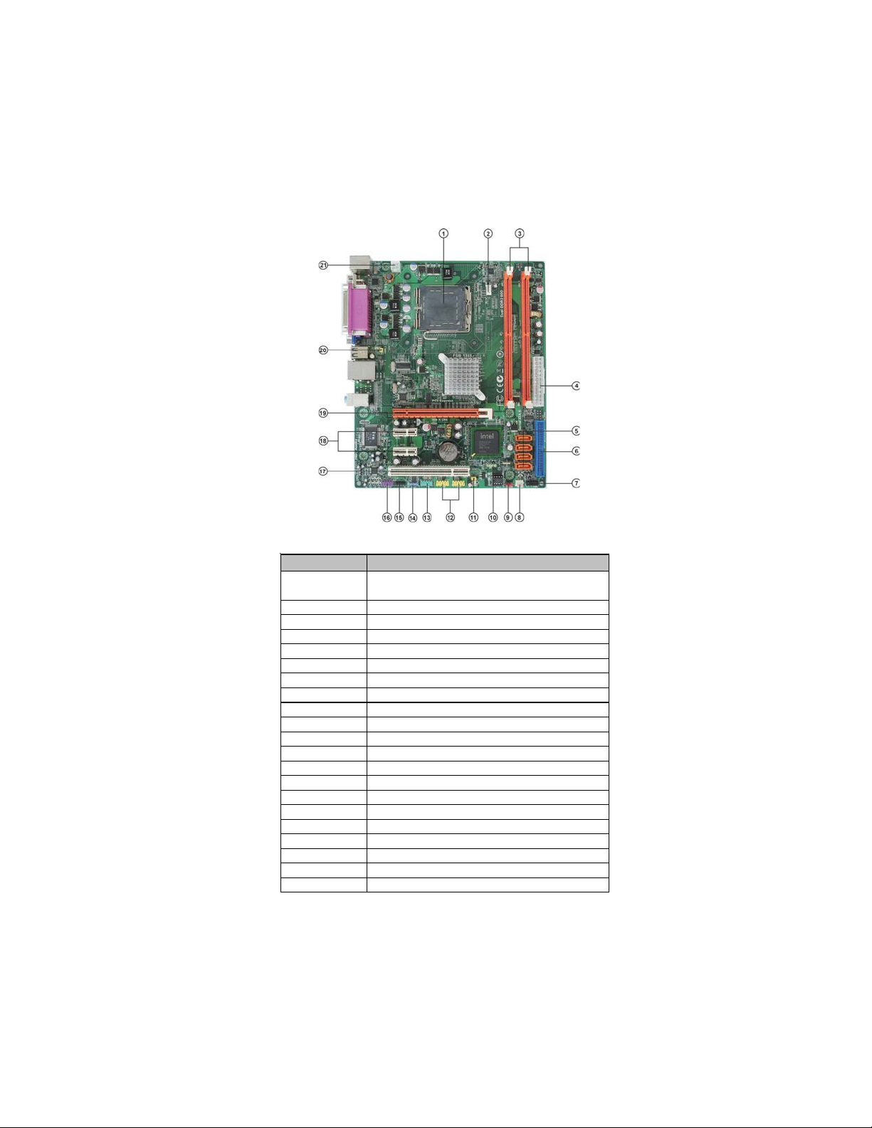
Motherboard Components
T
T
Table of Motherboard Components
5
LABEL COMPONENTS
1. CPU Socket
LGA775 socket for Intel
2 Duo/Pentium® Dual-core/Celeron® processors
®
Core
M
2 Quad/Core
M
2. CPU_FAN CPU cooling fan connector
3. DDR2_1~2 240-pin DDR2 SDRAM slots
4. ATX_POWER Standard 24-pin ATX power connector
5. SATA1~4 Serial ATA connectors
6. IDE Primary IDE channel
7. F_PANEL Front panel switch/LED header
8. SYS_FAN System cooling fan connector
9. CLR_CMOS Clear CMOS jumper
10. SPK Speaker header
11. USBPWR_F Front panel USB Power Select Jumper
12. F_USB1~2 Front panel USB headers
13. COM Onboard serial port header
14. SPDIFO SPDIF out header
15. CD_IN Analog audio input header
16. F_AUDIO Front panel audio header
17. PCI1 32-bit add-on card slot
18. PCIE1~2 PCI Express x1 slots
19. PCIEX16 PCI Express x16 graphics card slot
20. USBPWR_R Rear panel USB PS/2 Power Select Jumper
21. ATX12V 4-pin +12V power connector
This concludes Chapter 1. The next chapter explains how to install the motherboard.
Introducing the Motherboard

6
Memo
Introducing the Motherboard

Chapter 2
Installing the Motherboard
Safety Precautions
• Follow these safety precautions when installing the motherboard
• Wear a grounding strap attached to a grounded device to avoid damage from static electricity
• Discharge static electricity by touching the metal case of a safely
grounded object before working on the motherboard
• Leave components in the static-proof bags they came in
• Hold all circuit boards by the edges. Do not bend circuit boards
Choosing a Computer Case
There are many types of computer cases on the market. The motherboard complies
with the specifications for the Micro ATX system case. First, some features on the
motherboard are implemented by cabling connectors on the motherboard to indicators and switches on the system case. Make sure that your case supports all the
features required. Secondly, this motherboard supports two enhanced IDE drives.
Make sure that your case has sufficient power and space for all drives that you intend
to install.
Most cases have a choice of I/O templates in the rear panel. Make sure that the I/O
template in the case matches the I/O ports installed on the rear edge of the
motherboard.
This motherboard carries a Micro ATX form factor of 244 x 204 mm. Choose a case
that accommodates this form factor.
7
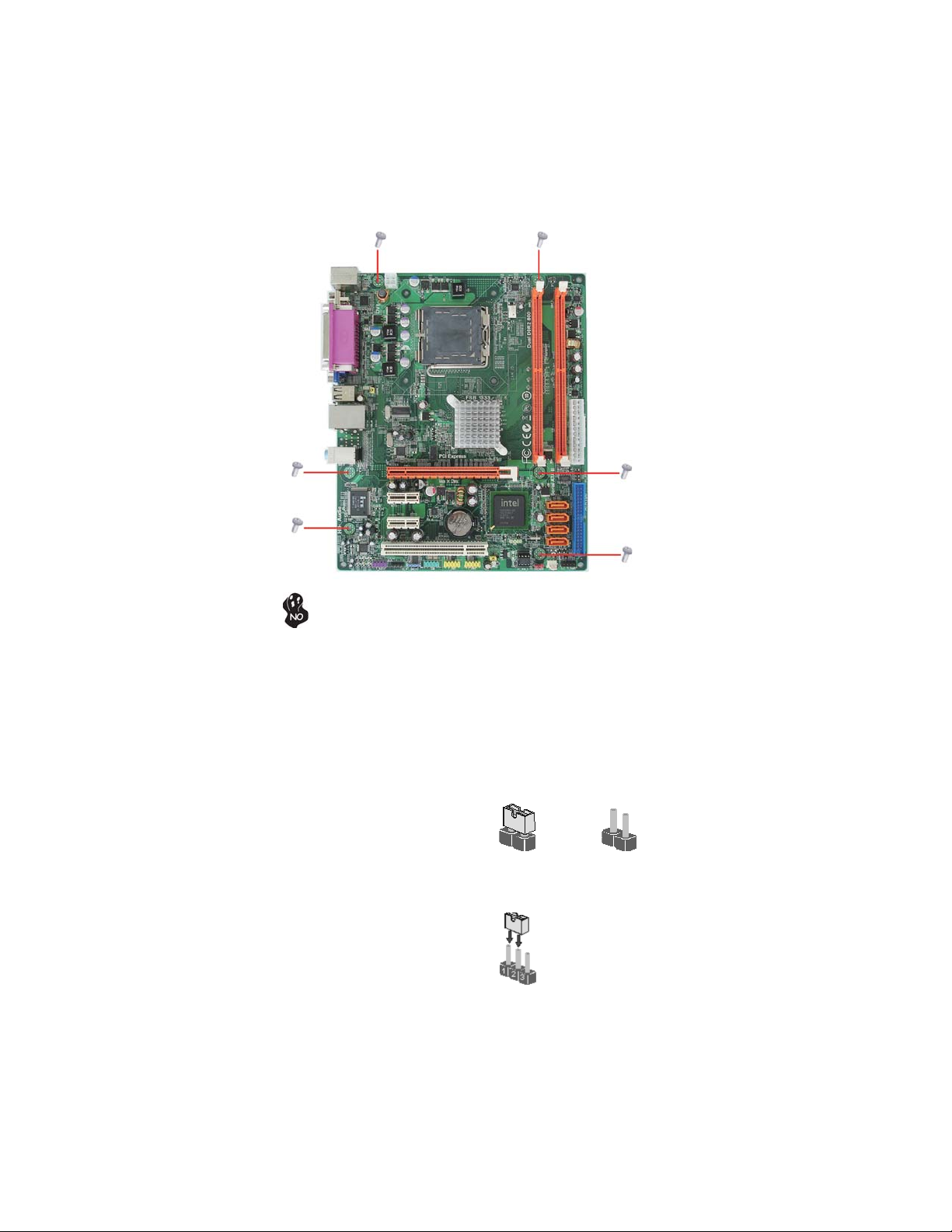
Installing the Motherboard in a Case
Refer to the following illustration and instructions for installing the motherboard in
a case.
Most system cases have mounting brackets installed in the case, which correspond
the holes in the motherboard. Place the motherboard over the mounting brackets
and secure the motherboard onto the mounting brackets with screws.
Ensure that your case has an I/O template that supports the I/O ports and expansion
slots on your motherboard.
Installing the Motherboard
8
Do not over-tighten the screws as this can stress the motherboard.
Checking Jumper Settings
This section explains how to set jumpers for correct configuration of the motherboard.
Setting Jumpers
Use the motherboard jumpers to set system configuration options. Jumpers with
more than one pin are numbered. When setting the jumpers, ensure that the jumper
caps are placed on the correct pins.
The illustrations show a 2-pin jumper.
When the jumper cap is placed on both
pins, the jumper is SHORT. If you remove the jumper cap, or place the jumper
cap on just one pin, the jumper is OPEN.
This illustration shows a 3-pin jumper.
Pins 1 and 2 are SHORT.
SHORT OPEN
Installing the Motherboard
Checking Jumper Settings
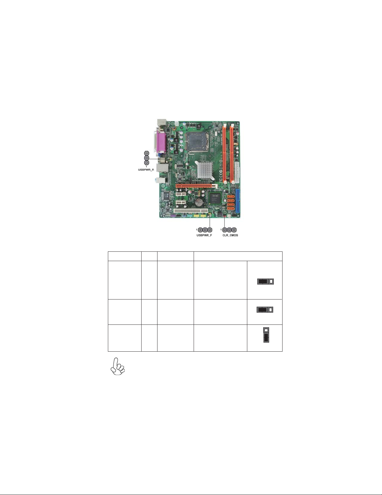
The following illustration shows the location of the motherboard jumpers. Pin 1 is
labeled.
Jumper Settings
9
Jumper
CLR_CMOS
USBPWR_F
USBPWR_R 3-pin
3-pin
3-pin
1. To avoid the system instability after clearing CMOS, we recommend
users to enter the main BIOS setting page to “Load Default Settings”
and then “Save and Exit Setup”.
2. Make sure the power supply provides enough 5VSB voltage before
selecting the 5VSB function.
3. It is required that users place the USBPWR_F & USBPWR_R cap onto
2-3 pin rather than 1-2 pin as default if you want to wake up the computer by USB/PS2 KB/Mouse.
Type
Description Setting (default)
1-2: NORMAL
Clear CMOS
Front Panel
USB Power
Select Jumper
Rear USB PS/2
Power Select
Jumper
2-3: CLEAR
Before clearing the
CMOS, make sure to
turn off the system.
Installing the Motherboard
1-2: VCC
2-3: 5VSB
1-2: VCC
2-3: 5VSB
1
CLR_CMOS
1
USBPWR_F
1
USBPWR_R

10
Installing Hardware
Installing the Processor
Caution: When installing a CPU heatsink and cooling fan make sure
that you DO NOT scratch the motherboard or any of the surfacemount resistors with the clip of the cooling fan. If the clip of the cooling
fan scrapes across the motherboard, you may cause serious damage
to the motherboard or its components.
On most motherboards, there are small surface-mount resistors near
the processor socket, which may be damaged if the cooling fan is
carelessly installed.
Avoid using cooling fans with sharp edges on the fan casing and the
clips. Also, install the cooling fan in a well-lit work area so that you
can clearly see the motherboard and processor socket.
Before installing the Processor
This motherboard automatically determines the CPU clock frequency and system bus
frequency for the processor. You may be able to change the settings in the system
Setup Utility. We strongly recommend that you do not over-clock processors or
other components to run faster than their rated speed.
Warning:
1. Over-clocking components can adversely affect the reliability of the
system and introduce errors into your system. Over-clocking can permanently damage the motherboard by generating excess heat in components that are run beyond the rated limits.
2. Always remove the AC power by unplugging the power cord from
the power outlet before installing or removing the motherboard or
other hardware components.
This motherboard has an LGA775 socket. When choosing a processor, consider the
performance requirements of the system. Performance is based on the processor
design, the clock speed and system bus frequency of the processor, and the quantity
of internal cache memory and external cache memory.
Installing the Motherboard
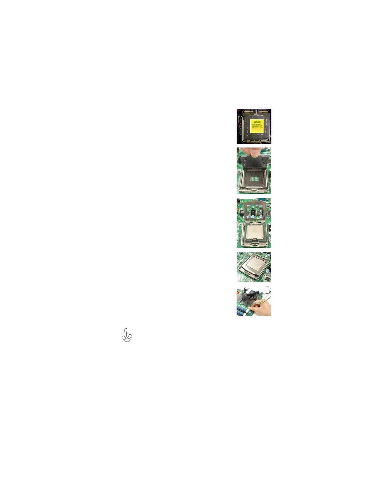
CPU Installation Procedure
The following illustration shows CPU installation components.
A. Read and follow the instructions shown
on the sticker on the CPU cap.
B. Unload the cap
· Use thumb & forefinger to hold the
lifting tab of the cap.
· Lift the cap up and remove the cap
completely from the socket.
C. Open the load plate
· Use thumb & forefinger to hold the
hook of the lever, pushing down and
pulling aside unlock it.
· Lift up the lever.
· Use thumb to open the load plate. Be
careful not to touch the contacts.
D. Install the CPU on the socket
· Orientate CPU package to the socket.
Make sure you match triangle marker
to pin 1 location.
E. Close the load plate
· Slightly push down the load plate onto
the tongue side, and hook the lever.
· CPU is locked completely.
11
F. Apply thermal grease on top of the CPU.
G. Fasten the cooling fan supporting base
onto the CPU socket on the motherboard.
H. Make sure the CPU fan is plugged to the
CPU fan connector. Please refer to the
CPU cooling fan user’s manual for more
detail installation procedure.
1. To achieve better airflow rates and heat dissipation, we suggest
that you use a high quality fan with 3800 rpm at least. CPU fan and
heatsink installation procedures may vary with the type of CPU fan/
heatsink supplied. The form and size of fan/heatsink may also vary.
2. DO NOT remove the CPU cap from the socket before installing a
CPU.
3. Return Material Authorization (RMA) requests will be accepted
only if the motherboard comes with the cap on the LGA775 socket.
Installing the Motherboard
12
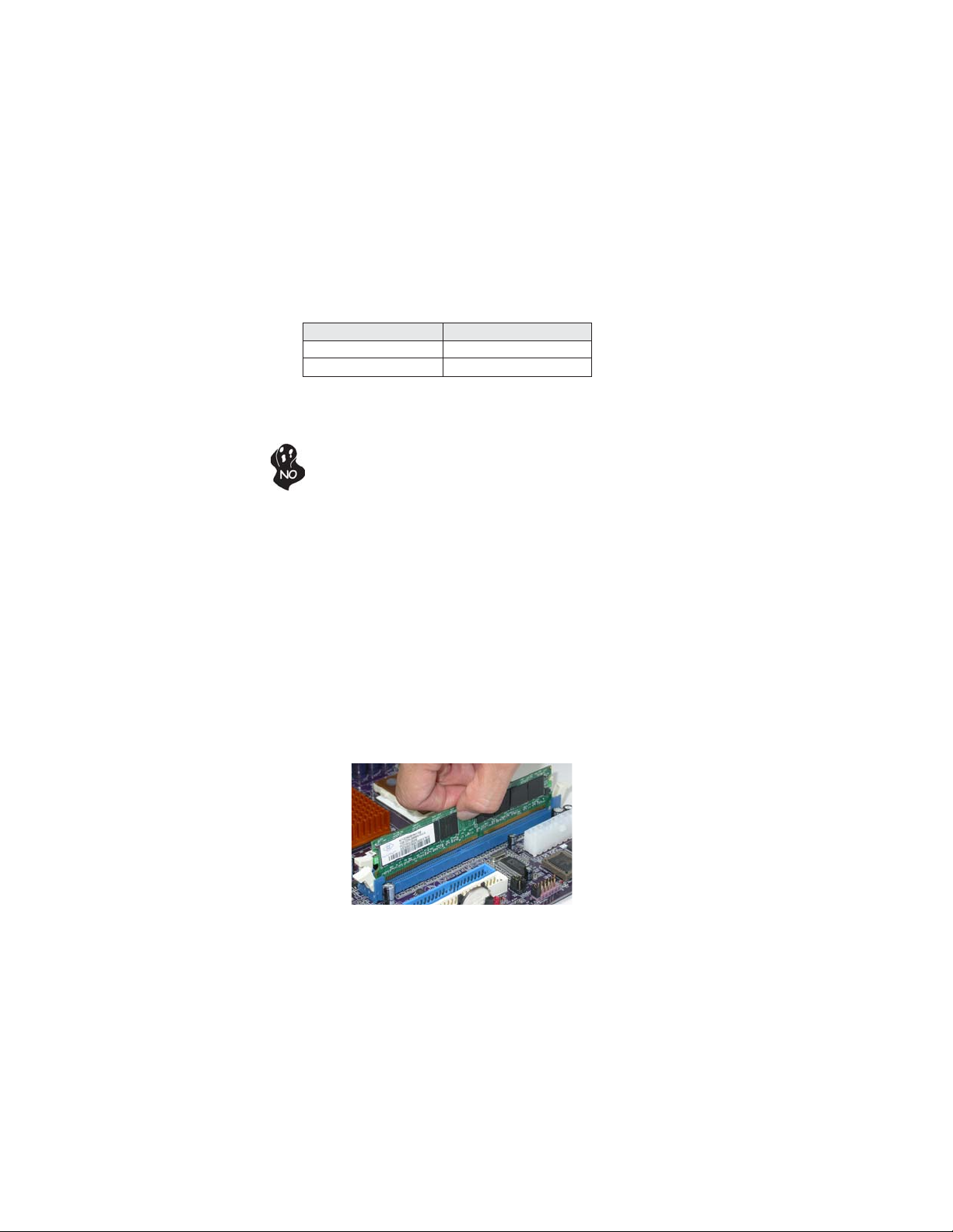
Installing Memory Modules
This motherboard accommodates two memory modules. It can support two 240-pin
DDR2 800/667. The total memory capacity is 8 GB.
DDR2 SDRAM memory module table
Memory module Memory Bus
DDR2 667 333 MHz
DDR2 800 400 MHz
You must install at least one module in any of the two slots. The total memory
capacity is up to 8 GB.
Do not remove any memory module from its antistatic packaging
until you are ready to install it on the motherboard. Handle the
modules only by their edges. Do not touch the components or metal
parts. Always wear a grounding strap when you handle the modules.
Installation Procedure
Refer to the following to install the memory modules.
1 This motherboard supports unbuffered DDR2 SDRAM .
2 Push the latches on each side of the DIMM slot down.
3 Align the memory module with the slot. The DIMM slots are keyed with
notches and the DIMMs are keyed with cutouts so that they can only be
installed correctly.
4 Check that the cutouts on the DIMM module edge connector match the
notches in the DIMM slot.
5 Install the DIMM module into the slot and press it firmly down until it
seats correctly. The slot latches are levered upwards and latch on to
the edges of the DIMM.
6 Install any remaining DIMM modules.
Installing the Motherboard

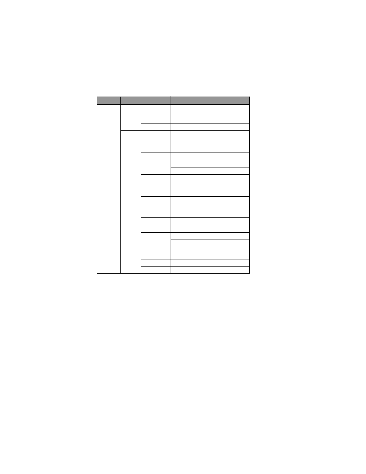
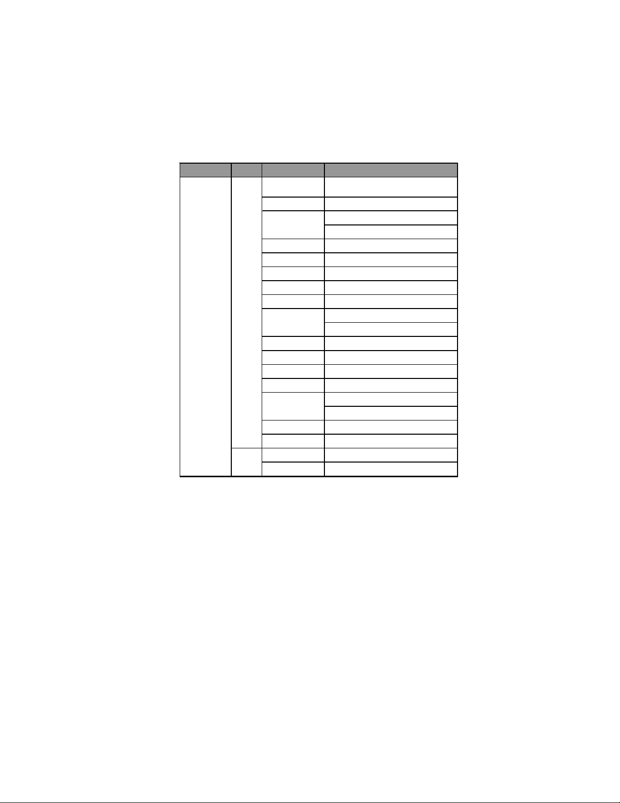
Table A: DDR2 (memory module) QVL (Qualified V endor List)
The following DDR2 800/667 memory modules have been tested and qualified for
use with this motherboard.
13
Type
DDR2 667
Size Vendor Module Name
Apacer 78.91G92.9K5
Micron MT4HTF6464AY-667E1
512 MB
1 GB
2 GB
4 GB
PSC AL6E8E63J-6E1
Ramxel RML1520M 38D6F-667
Samsung PC2-5300U-555-12-D3
Apacer
Corsair VS1GB667D2
Hexon HYNT7A UDR-30M48
Kingston KVR667D2N5
Micron M T8HTF12864AY-667E1
PSC
Samsung GOLD BAR M378T2863DZS 0742
Aeneon AET860UD00-30DB08X
Apacer 78.A1G9O.9K4
Hexon HYNT8A UDR-30M88
Hynix HYMP125U64AP8-Y5 AB-A 0623
Kingston KVR667D2N5
LeadMax PC2-5300U
PSC AL8E8F73C-6E1
Qimonda
Aeneon AET960UD00-30D
AU01GE667C5KBGC
78.01G9O.9K 5
AL7E8E63B-6E1T
AL7E8F63J-6E 1
AL7E8F73C-6E1
HYS64T256020EU-3S-C2
HYS72T64000HU-2.5-B
Installing the Motherboard
14
Type
DDR2 800
Size Vendor Module Name
KVR800D2N5/512 1.8V 9905315-
019.A02LF
AET760UD00-30DB97X
AET760UD00-25DC08X
AU01GE800C5KB GC
78.01GAO.9K5
78.01GA0.9L5
KVR800D2N5/1G 1.8V 9905316-
054.A01LF
GOLD BAR M378T2953EZ3-CE7 0726
M 3 78T2863EHS-CF7 0849
512 MB
1 GB
Kingston
M icron MT8HTF6464AY-80ED4
Qimonda HYS72T 6 40 00HU-2.5-B
A-DATA M2GVD6G 3I41P0U 1E5E
Aeneon
Apacer
Geil Geil Millenary
Hexon ELPT7AUDR-25M48
Hynix HYMP112U64CP8-S6 AB
KingMax KLDD48F-B8KU5 NGES
Kingston
Nanya NT1GT64U88D0BY-AD
Ramaxel RML1320EH38D7F-800
Samsung
Silicon Power SP001GBLRU800S01
Transcend 507301-1571
Unifosa GU341G0ALEPR6B2C6CE
Installing the Motherboard
15
Type
DDR2 800
Size Vendor Module Name
A-DATA Red A-data M2OMI6H3J4720L1C5Z
Aeneon AET860UD00-25DC08X
78.A1GAO.9K4
78.A1GC0.9L4
KVR800D2N5/2G
KVR800D2N6/2G-SP
M378T5663QZ3-C F7
M378T5663EH3-CF7
2 GB
4 GB
Apacer
CORSAIR CM2X2048-6400C5
Geil Geil Platinum Edition
Hexon E LP T8AUDR-25M88
Hynix HYMP125U64CP8-S6 AB
KingMax KLDE88F-B8KU5 NHES
Kingston
Micron MT 16 HTF256 64AY-800E 1
Nanya NT2GT64U8HD0BY-AD
PSC AL8E8F73C -8E1
Qimonda HYS64T256020EU-25F-C2
Samsung
Silicon Power SP002GBLRU800S01
Unifosa GU342G0ALEPR692C6CE
Aeneon AET960UD00-25D
Samsung M378T5263AZ3-CF7 0819
Installing the Motherboard
16
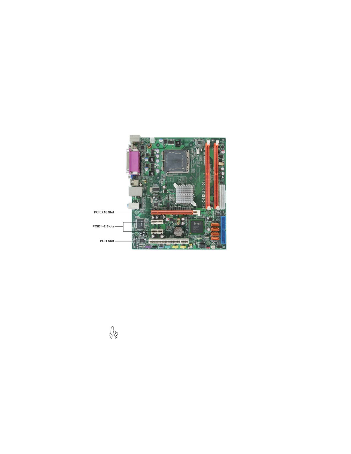
Expansion Slots
Installing Add-on Cards
The slots on this motherboard are designed to hold expansion cards and connect
them to the system bus. Expansion slots are a means of adding or enhancing the
motherboard’s features and capabilities. With these efficient facilities, you can increase the motherboard’s capabilities by adding hardware that performs tasks that are
not part of the basic system.
PCIEX16 Slot
PCIE1~2 Slots
PCI1 Slot
The PCI Express slot is used to install an external PCI Express
graphics card that is fully compliant to the PCI Express Gen 1.
The PCI Express x1 slots are fully compliant to the PCI Express
Base Specification revision 1.0a.
This motherboard is equipped with one standard PCI slot. PCI stands
for Peripheral Component Interconnect and is a bus standard for
expansion cards, which for the most part, is a supplement of the
older ISA bus standard. The PCI slot on this board is PCI v2.3
compliant.
Before installing an add-on card, check the documentation for the
card carefully. If the card is not Plug and Play, you may have to
manually configure the card before installation.
Installing the Motherboard
 Loading...