

Page 1

Preface
Preface
Copyright
This publication, including all photographs, illustrations and software, is protected
under international copyright laws, with all rights reserved. Neither this manual, nor
any of the material contained herein, may be reproduced without written consent of
the author.
Version 1.0A
Disclaimer
The information in this document is subject to change without notice. The manufacturer makes no representations or warranties with respect to the contents hereof and
specifically disclaims any implied warranties of merchantability or fitness for any
particular purpose. The manufacturer reserves the right to revise this publication and
to make changes from time to time in the content hereof without obligation of the
manufacturer to notify any person of such revision or changes.
FCC
This equipment has been tested and found to comply with the limits for a Class B
digital device, pursuant to Part 15 of the FCC Rules. These limits are designed to
provide reasonable protection against harmful interference in a residential installation. This equipment generates, uses, and can radiate radio frequency energy and, if
not installed and used in accordance with the instructions, may cause harmful interference to radio communications. However, there is no guarantee that interference
will not occur in a particular installation. If this equipment does cause harmful
interference to radio or television reception, which can be determined by turning the
equipment off and on, the user is encouraged to try to correct the interference by one
or more of the following measures:
• Reorient or relocate the receiving antenna
• Increase the separation between the equipment and the receiver
• Connect the equipment onto an outlet on a circuit different from that to
which the receiver is connected
• Consult the dealer or an experienced radio/TV technician for help
Shielded interconnect cables and a shielded AC power cable must be employed with
this equipment to ensure compliance with the pertinent RF emission limits governing this device. Changes or modifications not expressly approved by the system’s
manufacturer could void the user’s authority to operate the equipment.
Trademark Recognition
Windows® VISTA/7 are registered trademarks of Microsoft Corp.
Other product names used in this manual are the properties of their respective
owners and are acknowledged.
Page 2

ii
Preface
Canadian Department of Communications
This class B digital apparatus meets all requirements of the Canadian Interferencecausing Equipment Regulations.
Cet appareil numérique de la classe B respecte toutes les exigences du Réglement sur
le matériel brouilieur du Canada.
Declaration of Conformity
This device complies with part 15 of the FCC rules. Operation is subject to the
following conditions:
• This device may not cause harmful interference, and
• This device must accept any interference received, including interference that may cause undesired operation
CE
This product has been tested and found to comply with the limits of the European
Council Directive on the approximation of the laws of the member states relating to
electromagnetic compatibility according to 2004/108/EC.
Page 3

Preface
iii
Safety Instructions
Your system is designed and tested to meet the latest standards of safety for information technology equipment. However, to ensure your safety, it is important that you
read the following safety instructions.
Setting up your system
• Read and follow all instructions in the documentation before you operate your system.
• Do not use this product near water or a heated source such as a
radiator.
• Set up the system on a stable surface.
• Openings on the chassis are for ventilation. Do not block or cover these
openings. Make sure you leave plenty of space around the system for
ventilation. Never insert objects of any kind into the ventilation openings.
• Use this product in environments with ambient temperatures between
0°C and 40°C.
• If you use an extension cord, make sure that the total ampere rating of
the devices plugged into the extension cord does not exceed its ampere rating.
Attention during use
• Do not step on the power cord or let anything rest on top of it.
• Do not spill water or any other liquid on your system.
• When the system is turned OFF, a small amount of electrical current still
flows. Always unplug all power, modem, and network cables from the
power outlets before cleaning the system.
• If you encounter the following technical problems with the product,
unplug the power cord and contact a qualified service technician or
your retailer.
• The power cord or plug is damaged.
• Liquid has been spilled into the system.
• The system does not function properly even if you follow the
operating instructions.
• The system was dropped or the cabinet is damaged.
• The system performance changes
The warranty does not apply to products that have been disassembled by
users.
Page 4

iv
Preface
Safety cautions and warnings
Optical Drive Satety Information
CAUTION:
Invisible laser radiation when open. Do not stare into beam or view
directly with optical instructions.
WARNING:
Makeing adjustments or performing procedures other than those specified in the user’s manual may result in hazardous laser exposuer. Do
not attempt to disassemble the optical drive. For your safety, have the
optical drive serviced only by an authorized service provider.
Optical drive sold with this system contains a CLASS 1 LASER PRODUCT.
Product disposal notice
INPORTANT:
This symbol if the crossed out wheeled bin indicates that the product
(electrical and electronic equipment) should not be placed in municipal waste. Check local regulations for disposal of electronic products.
Nordic Lithium Cautions (for lithium-ion batteries)
CAUTION:
Danger of explosoin if battery is incorrectly replace only with the same
or equivalent type recommended by the manufacturer. Dispose of used
batteries according to the manufacturer’s instructions.
Product disposal notice
1. Do not place this product underneath heavy loads or in an unstable
position.
2. Do not use or expose this product around magnetic fields as magnetic interference may affect the performance of the product.
3. Do not expose this product to high levels of direct sunlight, highhumidity or wet conditions.
4. Do not block the air vents to this product or impede the airflow in
any way.
Page 5

v
TT
TT
T
ABLE OF CONTENTSABLE OF CONTENTS
ABLE OF CONTENTSABLE OF CONTENTS
ABLE OF CONTENTS
Preface i
Chapter 1 1
Introducing the PC 1
Introduction......................................................................................1
1.1 Specfications..............................................................................1
1.2 Front view...................................................................................2
1.3 Left and right view of the computer.......................................3
1.4 Back view....................................................................................5
1.5 Connecting your computer......................................................8
Packing Contents...........................................................................10
Chapter 3
3131
3131
31
Trouble Shooting 31
Start up problems during assembly............................................31
Solving Problems........................................................................31
Display Problems............................................................................31
Trouble shooting Audio Problems...................................................32
Maintenance and care tips.................................................................33
Chapter 2 11
Using BIOS 11
About the Setup Utility........................ ......................................... 11
The Standard Configuration........................ ...........................11
Entering the Setup Utilities......................................................11
Resetting the Default CMOS Values.......................................12
Using BIOS......................................................................................12
BIOS Navigation Key.............................................................13
Main Menu.............................................................................13
Advanced Menu......................................................................14
Chipset Menu..........................................................................23
Boot Menu..............................................................................26
Security Menu........................................................................27
Save & Exit Menu...................................................................28
Updating the BIOS..................................................................30
Page 6

vi
Memo
Page 7

1
Introducing the PC
Chapter 1
Introducing the PC
Introduction
Thank you for choosing G11 of great performance and with stylish and flexible
design. The G11 will give you an exciting PC experience for it allows you to choose
your own favorite motherboard to install.
1.1 Specifications
• L6 w/ MB:
-Sandy Bridge (LGA1155) up to 65W
-Intel Core i7/i5/i3, Pentium CPU options at 65W
• L5 w/o MB: depend on MB specification
Processor
(Optional for L6
w/ motherboard)
• Power, Brightness up/down, Display On/Off (depends
on motherboard support)
Button
• Support 2 x SO-DIMM DDR3 1333/1066 MHz, up to
8GB
• Built-in 1.3M pixel webcam/MIC
• 2 x USB 2.0
• 2 x Audio jacks (Headphone out, MIC-IN)
• 1 x Multi card reader (SD/MMC/MS)
• 1 x DC-IN
• 1 x Audio Out
• 4 x USB 2.0
• 1 x HDMI Out
• 1 x Giga Lan
Memory (L6
w/ motherboard)
Webcam
I/O (Side)
Rear Panel
• 19v, 150w power adapter
Power
Display Panel
• 21.5” wide screen 16:9 HD LED Panel
(panel voltage 5v, back
light converter voltage 19v)
Max resolution 1920 x 1080
• Optional Panel:
Resistive 10-finger multi-touch panel
Optical 2-finger touch panel
Non-touch panel
(Options may vary)
• Support 1 x 3.5” HDD
• Support 1 x SATA II Slim DVD Super-multi Tray type
Drive Bays
• 565(W) x 440(H) x 60(D) mm
• Net Weight: 9.1Kg
• Gross Weight: 11.5Kg
Dimension
• Thin Mini-ITX form factor
Form Factor
• 1 x Mini PCIe (Half-card w/USB signal)
Expansion
Page 8

2
Introducing the PC
WARNING:
Do not thrust the speaker with your fingers or sharp-pointed things such as
pens.
Webcam
The built-in webcam with the microphone can be used for picture taking, video
recoding, online conferencing and any other interactive applications.
Built-in Microphone
The built-in microphone can be used for video chatting online.
LCD/LED Display
The 21.5-inch TFT LCD/LED display is with an optimal resolution of 1920X 1080.
Speakers
The built-in stereo speakers deliver high quality sound blaster with stereo system
and Hi-Fi function supported.
1.2 Front view
Note:
ID design may vary.
Page 9

3
Introducing the PC
1. Power button
2. Brightness up
3. Brightness down
4. Display On/Off (Depend on motherboard support)
1.3 Left and right view of the computer
1.Power Button
Press the power button to turn the system on and off. The blue power LED is
when you turn on the system; the blue power LED is off when you turn off
the system.
2.Brightness up
Press this button to turn up the brightness of screen.
3.Brightness down
Press this button to turn down the brightness of screen.
4.Display On/Off (Depend on motherboard support)
Press the auto button to turn on or turn off the display.
Page 10

4
Introducing the PC
5.Optical Drive
Press the eject button to open the optical disk drive. The ODD LED is on
when CD/ DVD is read from or written to the optical disk drive.
6. USB Ports
The USB (Universal Serial Bus) port is provided for attaching USB devices such
as mouse, keyboard, printer, scanner, camera, PDA or other USB compatible
devices.
7. Headphone Jack (Green)
This is a jack for headphone.
8. MIC Jack (Pink)
This is a jack for microphone.
9. Multi Card Reader
The built-in card reader may support various types of memory card, such as XD
(eXtreme Digital), SD (Secure Digital), SDHC (SD High Capacity), MS (Memory
Stick), MS Pro (Memory Stick Pro) or MMC (Multi-Media Card) cards that usually
used in devices like digital cameras, MP3 players, mobile phones and PDAs.
Contact the local dealer for further information and please be noted that the
supported memory cards may vary without notice.
5. Optical drive
6. USB ports
7. Headphone Jack
8. MIC Jack
9. Multi Card reader
Page 11

5
Introducing the PC
1.4 Back view
Ventilator
The ventilator on the enclosure is used for air convection and to prevent the
equipment from overheating. Do not cover the ventilator.
Attention:
Be sure not to block any air vent on the computer. Blocked air vents may
cause thermal problems.
Page 12
6
Introducing the PC
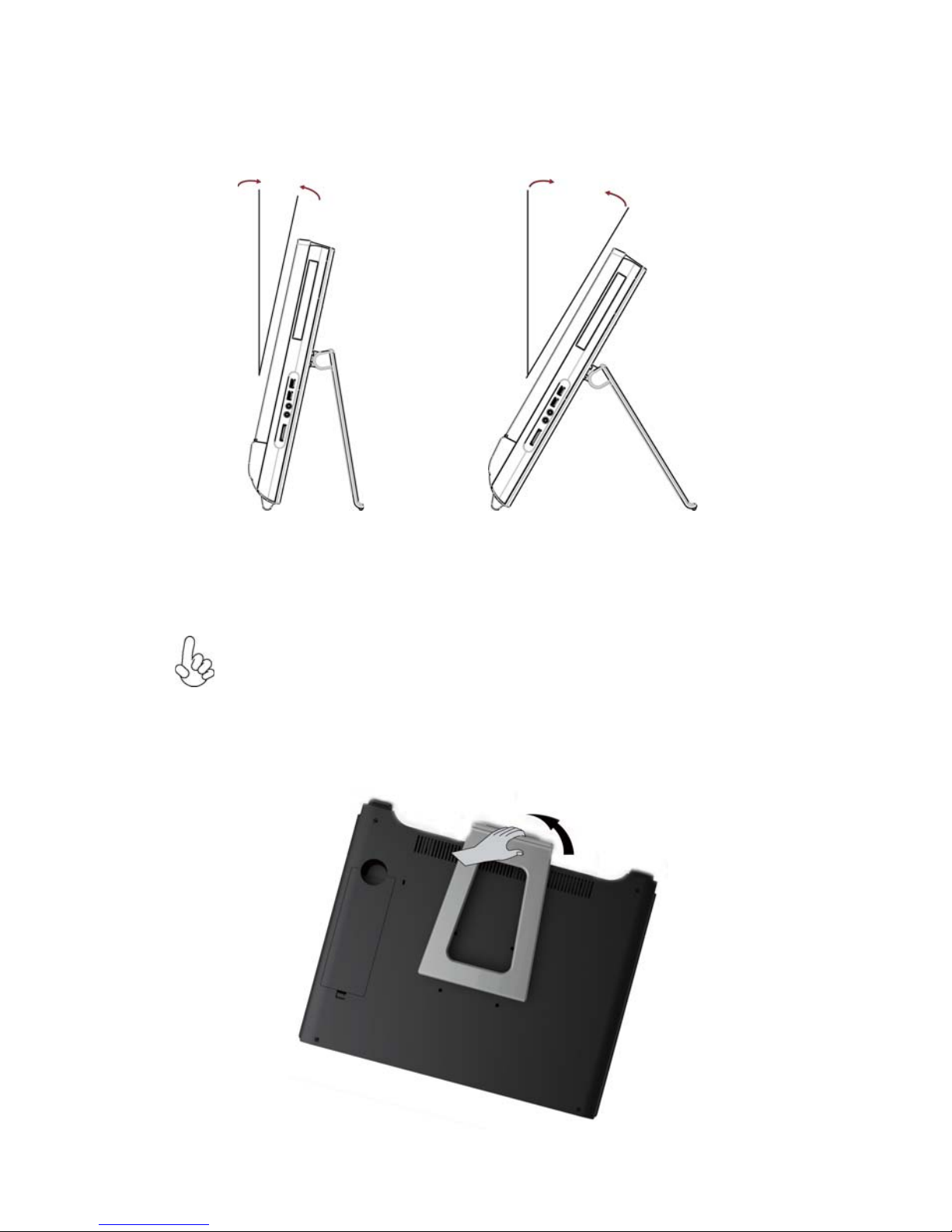
Computer stand
12°min. 30°max.
Use the stand to position the display to your preference. It can be rotated
between 12
o
and 30o from the vertical.
The stand provides stability to the computer; it is not a removable part.
Attention:
1. The computer stand must remain installed at all times to ensure maximum
system stability.
2. Make sure the angle of the computer is at least 12 degrees from the
vertical; otherwise the computer will be unstable and could fall over.
To open the computer stand, do the following:
Page 13

7
Introducing the PC
I/O Inside
There are many ports behind the back door, such as USB ports, Lan connector and audio jacks. It mainly depends on the motherboard you choose.
Please refer to the specification in Chapter 1.
1. Please remove the back door.
2. You will find the I/O position as below.
NOTE:
The descriptions in this part might vary from your computer, depending on
motherboard model and configurations.
Page 14

8
Introducing the PC
1.5 Connecting your computer
Use the following information to connect your computer:
Look for the small connector icons on the back of your computer. Match the
connectors to the icons.
1. Check the voltage rating before you connect the equipment to an electrical
outlet to ensure that the required voltage and frequency match the available
power source.
2. Connect the keyboard cable to the appropriate keyboard connector (PS2
connector or USB connector).
3. Connect the mouse cable to the appropriate mouse connector (PS2 connector
or USB connector).
Note:
Your computer might not have all of the connectors that are described in this
section. It mainly depend the motherboard you choose.
(Optional)
(Optional)
Note:
After you connect the AC/DC Adapter and the AC Power Core, please connect
the AC/DC Adapter to the DC-IN power connector in the Inside I/O port of
the computer first, then connect the AC Power Cord to the power.
Page 15

9
Introducing the PC
5. Your computer is equipped with a Memory Card Reader Connector, it is
able to read/write data from: SD/MMC, MS, MS pro, SD Pro.
4. Connect the R45J LAN cable to the LAN port.
Page 16

10
Introducing the PC
Packing Contents
NOTE:
Please contact us immediately if any of the items is damaged or missing.
Driver DVD
Manual
Quick Guide
Power Cable
Adapter
Heat Pipe & CPU Fan
(Options: depend
on motherboard)
Page 17

11
Using BIOS
About the Setup Utility
The computer uses the latest “American Megatrends Inc.” BIOS with support for
Windows Plug and Play. The CMOS chip on the motherboard contains the ROM
setup instructions for configuring the motherboard BIOS.
The BIOS (Basic Input and Output System) Setup Utility displays the system’s
configuration status and provides you with options to set system parameters. The
parameters are stored in battery-backed-up CMOS RAM that saves this information
when the power is turned off. When the system is turned back on, the system is
configured with the values you stored in CMOS.
The BIOS Setup Utility enables you to configure:
• Hard drives, diskette drives and peripherals
• Video display type and display options
• Password protection from unauthorized use
• Power Management features
The settings made in the Setup Utility affect how the computer performs. Before
using the Setup Utility, ensure that you understand the Setup Utility options.
This chapter provides explanations for Setup Utility options.
The Standard Configuration
A standard configuration has already been set in the Setup Utility. However, we
recommend that you read this chapter in case you need to make any changes in the
future.
This Setup Utility should be used:
• when changing the system configuration
• when a configuration error is detected and you are prompted to make
changes to the Setup Utility
• when trying to resolve IRQ conflicts
• when making changes to the Power Management configuration
• when changing the password or making other changes to the Security
Setup
Entering the Setup Utility
When you power on the system, BIOS enters the Power-On Self Test (POST)
routines. POST is a series of built-in diagnostics performed by the BIOS. After the
POST routines are completed, the following message appears:
Press DEL to enter SETUP
Chapter 2
Using BIOS
Page 18

12
Using BIOS
Press the delete key to access BIOS Setup Utility.
Using BIOS
When you start the Setup Utility, the main menu appears. The main menu of the
Setup Utility displays a list of the options that are available. A highlight indicates
which option is currently selected. Use the cursor arrow keys to move the highlight
to other options. When an option is highlighted, execute the option by pressing
<Enter>.
Some options lead to pop-up dialog boxes that prompt you to verify that you wish to
execute that option. Other options lead to dialog boxes that prompt you for information.
Some options (marked with a triangle
ff
ff
f) lead to submenus that enable you to change
the values for the option. Use the cursor arrow keys to scroll through the items in the
submenu.
Resetting the Default CMOS Values
When powering on for the first time, the POST screen may show a “CMOS
Settings Wrong” message. This standard message will appear following a clear
CMOS data at factory by the manufacturer. You simply need to Load Default
Settings to reset the default CMOS values.
Note: Changes to system hardware such as different CPU, memories, etc. may also
trigger this message.
BIOS Information
BIOS Version G11_0401 04/01/2011
System Data [ Wed 04/06/2011]
System Time [10:16:08]
Set the Date. Use Tab to
switch between Data elements.
Aptio Setup Utility - Copyright (C) 2011 American Megatrends, Inc.
Version 2.11.1210. Copyright (C) 2011, American Megatrends, Inc.
Main Advanced Chipset Boot Security Save & Exit
F1:General Help
+/- : Change Opt.
Enter : Select
lk
mn
:Select Screen
:Select Item
F2:Previous Values
F3:Optimized Defaults
F4:Save & Exit
ESC:Exit
Page 19

13
Using BIOS
BIOS Information
BIOS Version G11_0401 04/01/2011
System Data [ Wed 04/06/2011]
System Time [10:16:08]
The default BIOS setting for this motherboard apply for most conditions
with optimum performance. We do not suggest users change the default
values in the BIOS setup and take no responsibility to any damage
caused by changing the BIOS settings.
BIOS Navigation Keys
The BIOS navigation keys are listed below:
KEY FUNCTION
Scrolls through the items on a menu
+/- Modifies the selected field’s values
F2 Previous Value
F3 Optimized Defaults
F1 General Help
ESC Exits the current menu
mnlk
Enter Select
In this manual, default values are enclosed in parenthesis. Submenu items are denoted
by a triangle
ff
ff
f.
F4 Save & Exit
For the purpose of better product maintenance, the manufacture reserves
the right to change the BIOS items presented in this manual. The BIOS
setup screens shown in this chapter are for reference only and may differ
from the actual BIOS. Please visit the manufacture’s website for updated
manual.
When you enter the BIOS Setup program, the main menu appears, giving you an
overview of the basic system information. Select an item and press <Enter> to
display the submenu.
Main Menu
Set the Date. Use Tab to
switch between Data elements.
Aptio Setup Utility - Copyright (C) 2011 American Megatrends, Inc.
Version 2.11.1210. Copyright (C) 2011, American Megatrends, Inc.
Main Advanced Chipset Boot Security Save & Exit
F1:General Help
+/- : Change Opt.
Enter : Select
lk
mn
:Select Screen
:Select Item
F2:Previous Values
F3:Optimized Defaults
F4:Save & Exit
ESC:Exit
Page 20

14
Using BIOS
Date & Time
The Date and Time items show the current date and time on the computer. If you are
running a Windows OS, these items are automatically updated whenever you make
changes to the Windows Date and Time Properties utility.
The Advanced menu items allow you to change the settings for the CPU and
other system.
Advaned Menu
Launch PXE OpROM (Disabled)
Use this item to enable or disable the PXE OpROM.
Launch Storage OpROM (Enabled)
Use this item to enable or disable the Storage OpROM.
Legacy OpROM Support
Launch PXE OpROM [Disabled]
Launch Storage OpROM [Enabled]
LAN Configuration
PC Health Status
Power Management Setup
ACPI Settings
CPU Configuration
SATA Configuration
USB Configuration
Enable/Disable Onboard LAN
Option ROM
Aptio Setup Utility - Copyright (C) 2011 American Megatrends, Inc.
Version 2.11.1210. Copyright (C) 2011, American Megatrends, Inc.
ff
ff
f
ff
ff
f
ff
ff
f
ff
ff
f
ff
ff
f
ff
ff
f
ff
ff
f
Main Advanced Chipset Boot Security Save & Exit
BIOS Version (G11_0401 04/01/2011)
This item shows the information of the BIOS version.
F1:General Help
+/- : Change Opt.
Enter : Select
lk
mn
:Select Screen
:Select Item
F2:Previous Values
F3:Optimized Defaults
F4:Save & Exit
ESC:Exit
Page 21

15
Using BIOS
Onboard LAN Controller (Enabled)
Use this item to enable or disable the Onboard LAN.
Press <Esc> to return to the Advanced Menu page.
LAN Configuration
The item in the menu shows the LAN-related information that the BIOS
automatically detects.
Enable/Disable Onboard LAN
Controller
LAN Configuration
Onboard LAN Controller [Enabled]
Aptio Setup Utility - Copyright (C) 2011 American Megatrends, Inc.
Version 2.11.1210. Copyright (C) 2011, American Megatrends, Inc.
Main Advanced Chipset Boot Security Save & Exit
F1:General Help
+/- : Change Opt.
Enter : Select
lk
mn
:Select Screen
:Select Item
F2:Previous Values
F3:Optimized Defaults
F4:Save & Exit
ESC:Exit
Page 22

16
Using BIOS
PC Health Status
On motherboards support hardware monitoring, this item lets you monitor the
paeameters for critical voltages, temperatures and fan speeds.
Main Advanced Chipset Boot Security Save & Exit
CPU Fan Speed : 0 RPM
System Fan Speed : 1406 RPM
Version 2.11.1210. Copyright (C) 2011, American Megatrends, Inc.
Aptio Setup Utility - Copyright (C) 2011 American Megatrends, Inc.
-=- PECI Mode -=-
Offset to TCC Activation Temp. : -36
Smart Fan Function
f
PC Health Status
Aptio Setup Utility - Copyright (C) 2011 American Megatrends, Inc.
Version 2.10.1211. Copyright (C) 2011, American Megatrends, Inc.
CPU Smart Fan Control [Enabled]
Smart Fan Mode [Normal]
Smart Fan start PWM value 180
Smart Fan start PWM TEMP(-) 30
Delta T +3
Smart Fan Slope PWM value 10 PWM value/unite
CPU Fan Full Speed Offset (-) 23
System Smart Fan Control [Enabled]
Smart Fan Mode [Normal]
Smart Fan start PWM value 180
Smart Fan start PWM TEMP(-) 30
Delta T +3
Smart Fan Slope PWM value 10 PWM value/unite
System Fan Full Speed Offset (-) 23
Main Advanced Chipset Boot Security Save & Exit
Scroll to this item and press <Enter> to view the following screen:
fSmart Fan Function
CPU Smart Fan Control (Enabled)
This item allows you to enable/disable the control of the CPU fan speed by chang-ing
the fan voltage.
Smart Fan Mode (Normal)
This item allows you to select the fan mode (Normal, Quiet, Silent, or Manual) for a
better operation environment. If you choose Normal mode, the fan speed will be auto
adjusted depending on the CPU temperature. If you choose Quite mode, the fan speed
will be auto minimized for quiet environment. If you choose Silent mode, the fan
speed will be auto restricted to make system more quietly. If you choose Manual
mode, the fan speed will be adjust depending on users’ parameters.
Smart Fan Function
F1:General Help
+/- : Change Opt.
Enter : Select
lk
mn
:Select Screen
:Select Item
F2:Previous Values
F3:Optimized Defaults
F4:Save & Exit
ESC:Exit
F1:General Help
+/- : Change Opt.
Enter : Select
lk
mn
:Select Screen
:Select Item
F2:Previous Values
F3:Optimized Defaults
F4:Save & Exit
ESC:Exit
Enabled/Disabled CPU Smart Fan
Page 23

17
Using BIOS
• CPU Fan Speed
• System Fan Speed
System Component Characteristics
These items display the monitoring of the overall inboard hardware health
events, such as System & CPU temperature, CPU & DIMM voltage, CPU &
system fan speed,... etc.
Smart Fan start PWM value (180)
Smart Fan start TEMP(-) (30)
This item is used to set the start PWM value of the smart fan.
This item is used to set the start temperature of the smart fan.
DeltaT (+3)
This item specifies the range that controls CPU temperature and keeps it from going
so high or so low when smart fan works.
Smart Fan Slope PWM value (10 PWM value/unite)
This item is used to set the Slope Select PWM of the smart fan.
This item is used to set the CPU fan full speed offset value.
CPU Fan Full Speed Offset(-) (23)
Press <Esc> to return to the PC Health Status page.
Press <Esc> to return to the Advanced Menu page.
This item is used to set the system fan full speed offset value.
System Fan Full Speed Offset(-) (23)
System Smart Fan Control (Enabled)
This item allows you to enable/disable the control of the system fan speed by changing the fan voltage.
Page 24

18
Using BIOS
EUP Support (Enabled)
This item allows user to enable or disable EUP support.
Power Management Setup
This page sets up some parameters for system power management operation.
Resume By PCI-E/LanPME (Disabled)
The system can be turned off with a software command. If you enable this item, the
system can automatically resume if there is an incoming call on the PCI Modem or
PCI LAN card. You must use an ATX power supply in order to use this feature. Use
this item to do wake-up action if inserting the PCI card.
Resume By USB (S3) (Disabled)
This item allows you to enable/disable the USB device wakeup function from S3
mode.
Power Management Setup
Resume By PCI-E/Lan PME [Disabled]
Resume By USB (S3) [Disabled]
EUP Function [Enabled]
Aptio Setup Utility - Copyright (C) 2011 American Megatrends, Inc.
Main
Advanced Chipset Boot Security Save & Exit
Version 2.11.1210. Copyright (C) 2011, American Megatrends, Inc.
About Resume by PCI-E/Lan PME
Press <Esc> to return to the Advanced Menu page.
F1:General Help
+/- : Change Opt.
Enter : Select
lk
mn
:Select Screen
:Select Item
F2:Previous Values
F3:Optimized Defaults
F4:Save & Exit
ESC:Exit
Page 25

19
Using BIOS
ACPI Setting
The item in the menu shows the highest ACPI sleep state when the system
enters suspend.
ACPI Sleep State (S3(Suspend to RAM))
This item allows user to enter the ACPI S3 (Suspend toRAM) Sleep State(default).
Press <Esc> to return to the Advanced Menu page.
CPU Configuration
Scroll to this item and press <Enter> to view the following screen:
CPU Configuration
Intel(R) Core(TM) i5-2500T CPU @ 2.30GHz
Processor Stepping 206a7
Microcode Revision d
Processor Speed 2300 MHz
Processor Cores 4
Intel HT Technology Not Supported
EMT64 Supported
Limit CPUID Maximum [Disabled]
Execute Disable Bit [Enabled]
Intel Virtualization Technology [Enabled]
Power Technology [Custom]
CPU C3 Report [Disabled]
CPU C6 report [Enabled]
Package C State limit [No Limit]
Enhanced Intel SpeedStep Technolog [Enabled]
Turbo Mode [Enabled]
Aptio Setup Utility - Copyright (C) 2011 American Megatrends, Inc.
Version 2.11.1210. Copyright (C) 2011, American Megatrends, Inc.
Disabled for Windows XP
Main Advanced Chipset Boot Security Save & Exit
ACPI Settings
ACPI Sleep State [S3 (Suspend to RAM)]
Aptio Setup Utility - Copyright (C) 2011 American Megatrends, Inc.
Version 2.11.1210. Copyright (C) 2011, American Megatrends, Inc.
Select the highest ACPI sleep
state the system will enter
when the Suspend button is
pressed.
Main Advanced Chipset Boot Security Save & Exit
F1:General Help
+/- : Change Opt.
Enter : Select
lk
mn
:Select Screen
:Select Item
F2:Previous Values
F3:Optimized Defaults
F4:Save & Exit
ESC:Exit
F1:General Help
+/- : Change Opt.
Enter : Select
lk
mn
:Select Screen
:Select Item
F2:Previous Values
F3:Optimized Defaults
F4:Save & Exit
ESC:Exit
Page 26

20
Using BIOS
Intel(R) Core(TM) i5-2500T CPU @ 2.30GHz
This is display-only field and diaplays the information of the CPU installed in your
computer.
Processor Stepping (206a7)
This item shows the processor stepping version.
Microcode Revision (d)
This item shows the Microcode version.
Processor Cores (4)
This item shows the core number of the processor.
Excute Disable Bit (Enabled)
This item allows the processor to classify areas in memory by where application code
can execute and where it cannot. When a malicious worm attempts to insert code in
the buffer, the processor disables code execution, preventing damage or worm propagation. Replacing older computers with Execute Disable Bit enabled systems can halt
worm attacks, reducing the need for virus related repair.
Intel Virtualization Technology (Enabled)
When disabled, a VMM cannot utilize the additional hardware capabilities provided
by Vandor Pool Technology.
Power Technology (Custom)
Use this item to control the Energy mode of the processor.
Limit CPUID Maximum (Disabled)
Use this item to enable or disable the maximum CPUID value limit. When supports
Prescott and LGA775 CPUs, enables this to prevent the system from “rebooting”
when trying to install Windows NT 4.0.
Intel HT Technology (Not Supported)
This item shows that your computer supports Intel HT technology or not.
Processor Speed (2300MHz)
This item shows the current processor speed.
EMT64 (Supported)
This item shows the computer supports EMT64.
CPU C3 Report (Disabled)
Use this item to enable or disable CPU C3 (ACPI C2) report to OS.
CPU C6 report (Enabled)
Use this item to enable or disable the CPU C6 report to OS.
Package C State limit (No limit)
Use this item to limit the CPU to enter C state or not.
Press <Esc> to return to the Advanced Menu page.
Enhanced Intel SpeedStep Technolog (Enabled)
This item allows you to enable or disable the EIST (Enhanced Intel SpeedStep
Technology).
Turbo Mode (Enabled)
This item allows you to control the Intel Turbo Boost Technology.
Page 27

21
Using BIOS
SATA Configuration
Use this item to show the mode of serial SATA configuration options.
Serial-ATA Controller 0 (Compatible)
Use this item to select the Serial-ATA cotroller options: Disabled, Compatible, Enhanced.
SATA Mode (IDE Mode)
Use this item to select SATA mode.
SATA Configuration
SATA Mode [IDE Mode]
Serial-ATA Controller 0 [Compatible]
SATA Port1 :
SlimtypeDVD A ATAPI
SATA Port2 :
ST3500418AS (500.1GB)
Aptio Setup Utility - Copyright (C) 2011 American Megatrends, Inc.
Version 2.11.1210. Copyright (C) 2011, American Megatrends, Inc.
(1) IDE Mode. (2) AHCI Mode.
Main Advanced Chipset Boot Security Save & Exit
SATA Port 1~2 (Not Present)
This motherboard supports two SATA channel and each channel allows one SATA
device to be installed. Use these items to configure each device on the SATA channel.
Press <Esc> to return to the Advanced Menu page.
F1:General Help
+/- : Change Opt.
Enter : Select
lk
mn
:Select Screen
:Select Item
F2:Previous Values
F3:Optimized Defaults
F4:Save & Exit
ESC:Exit
Page 28

22
Using BIOS
USB Configuration
Scroll to this item and press <Enter> to view the following screen:
Legacy USB Support (Enabled)
Use this item to enable or disable support for legacy USB devices. Setting to Audio
allows the system to detect the presence of the USB device at startup. If detected, the
USB controller legacy mode is enabled. If no USB device is detected, the legacy USB
support is disabled.
USB Configuration
Aptio Setup Utility - Copyright (C) 2011 American Megatrends, Inc.
Version 2.11.1210. Copyright (C) 2011, American Megatrends, Inc.
Enables Legacy USB support.
AUTO option disables legacy
support if no USB devices are
connected. Disabled option
will keep USB devices
available only for EFI
applications.
Legacy USB Support [Enabled]
Main
Advanced Chipset Boot Security Save & Exit
Press <Esc> to return to the Advanced Menu page.
F1:General Help
+/- : Change Opt.
Enter : Select
lk
mn
:Select Screen
:Select Item
F2:Previous Values
F3:Optimized Defaults
F4:Save & Exit
ESC:Exit
Page 29

23
Using BIOS
Press <Esc> to return to the chipset menu page.
fNorth Bridge
Scroll to this item and press <Enter> and view the following screen:
IGD Memory (64M)
This item shows the information of the IGD(Internal Graphics device) memory.
DVMT Mode Select (DVMT Mode)
This item allows you to select the DVMT operating mode.
DVMT/FIXED Memory (256MB)
When set to Fixed Mode, the graphics driver will reserve a fixed position of the
system memory as graphics memory, according to system and graphics requirements.
The chipset menu items allow you to change the settings for the North chipset,
South chipset and other system.
Chipset Menu
Aptio Setup Utility - Copyright (C) 2011 American Megatrends, Inc.
Version 2.11.1210. Copyright (C) 2011, American Megatrends, Inc.
North Bridge Parameters
North Bridge
South Bridge
f
f
f
ME Subsystem
Main Advanced Chipset Boot Security Save & Exit
Aptio Setup Utility - Copyright (C) 2011 American Megatrends, Inc.
Version 2.11.1210. Copyright (C) 2011, American Megatrends, Inc.
Main Advanced Chipset Boot Security Save & Exit
North Bridge
IGD Memory [64M]
DVMT Mode Select [DVMT Mode]
DVMT/FIXED Memory [256MB]
IGD Share Memory Size
F1:General Help
+/- : Change Opt.
Enter : Select
lk
mn
:Select Screen
:Select Item
F2:Previous Values
F3:Optimized Defaults
F4:Save & Exit
ESC:Exit
F1:General Help
+/- : Change Opt.
Enter : Select
lk
mn
:Select Screen
:Select Item
F2:Previous Values
F3:Optimized Defaults
F4:Save & Exit
ESC:Exit
Page 30

24
Using BIOS
fSouth Bridge
Scroll to this item and press <Enter> to view the following screen:
Restore AC Power Loss (Power Off)
This item enables your computer to automatically restart or return to its operating
status.
Audio Configuration
This item shows the information of the audio configuration.
Azalia HD Audio (Enabled)
This item enables or disables Azalia HD audio.
Azalia Internal HDMI codec (Enabled)
This item enables or disables Azaia Internal HDMI codec.
Press <Esc> to return to the chipset menu page.
Aptio Setup Utility - Copyright (C) 2011 American Megatrends, Inc.
Version 2.11.1210. Copyright (C) 2011, American Megatrends, Inc.
Specify what state to go to
when power is re-applied
after a power failure (G3
state).
South Bridge
Restore AC Power Loss [Power Off]
Audio Configuration
Azalia HD Audio [Enabled]
Azalia Internal HDMI codec [Enabled]
Main Advanced Chipset Boot Security Save & Exit
F1:General Help
+/- : Change Opt.
Enter : Select
lk
mn
:Select Screen
:Select Item
F2:Previous Values
F3:Optimized Defaults
F4:Save & Exit
ESC:Exit
Page 31

25
Using BIOS
Aptio Setup Utility - Copyright (C) 2011 American Megatrends, Inc.
Version 2.11.1210. Copyright (C) 2011, American Megatrends, Inc.
ME Subsystem Help
Intel ME Subsystem Configuration
ME Version 7. 0. 10. 1203
ME Subsystem [Enabled]
Main Advanced Chipset Boot Security Save & Exit
f ME Subsystem
Scroll to this item and press <Enter> to view the following screen:
ME Version (7.0.10.1203)
This item shows the ME version.
ME Subsystem (Enabled)
This item allows you to enable or disable ME subsystem.
Press <Esc> to return to the chipset menu page.
F1:General Help
+/- : Change Opt.
Enter : Select
lk
mn
:Select Screen
:Select Item
F2:Previous Values
F3:Optimized Defaults
F4:Save & Exit
ESC:Exit
Page 32

26
Using BIOS
This page enables you to set the keyboard NumLock state.
Boot Menu
Boot Configuration
This item shows the information of the boot configuration.
Quiet Boot (Disabled)
This item enables or disables quiet boot.
Setup Prompt Timeout (1)
This item is used to set the number of seconds to wait for setup activation key.
Aptio Setup Utility - Copyright (C) 2011 American Megatrends, Inc.
Version 2.11.1210. Copyright (C) 2011, American Megatrends, Inc.
Enabled/Disabled Quiet Boot
option
Main Advanced Chipset Boot Security Save & Exit
Boot Configuration
Quiet Boot [Disabled]
Setup Prompt Timeout 1
CSM16 Module Version 07.64
GateA20 Active [Upon Request]
Option ROM Messages [Force BIOS]
Interrupt 19 Capture [Enabled]
Set Boot Prioritiy
1st Boot [CD/DVD: SlimtypeDV ...]
2nd Boot [Hard Disk: ST35004 ...]
3rd Boot [USB Floppy]
4th Boot [USB CD/DVD]
5th Boot [USB Hard Disk]
6th Boot [USB KEY: U3 Innosto ...]
7th Boot [Network]
8th Boot [UEFI: USB USB Hard ...]
CD/DVD ROM Drive BBS Priorities
Hard Disk Drive BBS Priorities
USB KEY Drive BBS Priorities
UEFI Boot Drive BBS Priorities
CSM16 Module Version (07.64)
This item shows the information of the CSM16 Module Version.
F1:General Help
+/- : Change Opt.
Enter : Select
lk
mn
:Select Screen
:Select Item
F2:Previous Values
F3:Optimized Defaults
F4:Save & Exit
ESC:Exit
f
f
f
f
GateA20 Active (Upon Request)
This item can be set to Upon request or Always. When it is upon request, GA20 can
be disabled using BIOS services. When it is Always, do not allow disabling GA20, this
option is useful when any RT code is executed above 1MB.
Option ROM Messages (Force BIOS)
This item is used to set display mode for option ROM.
Interrupt 19 Capture (Enabled)
This item enables or disables option ROMs to trap Int 19.
Set Boot Priority
This item enables you to select boot priority for all boot devices.
Page 33

27
Using BIOS
Version 2.11.1210. Copyright (C) 2011, American Megatrends, Inc.
This page enables you to set setup administrator and password.
Security Menu
Aptio Setup Utility - Copyright (C) 2011 American Megatrends, Inc.
Set Setup Administrator
Password
Main Advanced Chipset Boot Security Save & Exit
Administrator Password
This item allows you to set up the administrator password.
If ONLY the Administrator’s password is set,
then this only limits access to Setup and is
only asked for when entering Setup.
If ONLY the User’s password is set, then this
is a power on password and must be entered to
boot or enter Setup. In Setup the User will
have Administrator rights.
The password must be 3 to20 characters long.
Administrator Password
User Password
Security Check [Setup]
User Password
This item allows you to install or change a password.
Security Check (Setup)
You can select this option and press <Enter> to access the sub menu. You can use the
sub menu to change the supervisor password.
F1:General Help
+/- : Change Opt.
Enter : Select
lk
mn
:Select Screen
:Select Item
F2:Previous Values
F3:Optimized Defaults
F4:Save & Exit
ESC:Exit
1st/2nd/3rd/4th/5th/6th/7th/8th Boot
These items shows the boot priorities.
CD/DVD ROM Drive BBS Priorities
This item enables you to specify the sequence of loading the operating system from
the installing CD/DVD ROM drives.
Hard Disk Drive BBS Priorities
This item enables you to specify the sequence of loading the operating system from
the installing hard disk drives.
USB KEY Drive BBS Priorities
This item enables you to specify the sequence of loading the operating system from
the installing USB KEY drives.
UEFI Boot Drive BBS Priorities
This item enables you to specify the sequence of loading the operating system from
the installing UEFI Boot drives.
Page 34

28
Using BIOS
Boot Override
Use this item to select the boot device.
This page enables you to exit system setup after saving or without saving the
changes.
Save & Exit Menu
Save Changes and Exit
This item enables you to save the changes that you have made and exit.
Discard Changes and Exit
This item enables you to discard any changes that you have made and exit.
Save Changes and Reset
This item enables you to save the changes that you have made and reset.
Save Options
This item enables you to save the options that you have made.
Save Changes
This item enables you to save the changes that you have made.
Discard Changes
This item enables you to discard any changes that you have made.
Restore Defaults
This item enables you to restore the system defaults.
Save as User Defaults
This item enables you to save the changes that you have made as user defaults.
Restore User Defaults
This item enables you to restore user defaults.
Save Changes and Exit
Discard Changes and Exit
Save Changes and Reset
Discard Changes and Reset
Save Options
Save Changes
Discard Changes
Restore Defaults
Save as User Defaults
Restore User Defaults
Boot Override
SATA: SlimtypeDVD A DS8A5S
SATA: ST3500418AS
Launch EFI Shell from filesystem device
Main Advanced Chipset Boot Security Save & Exit
Aptio Setup Utility - Copyright (C) 2011 American Megatrends, Inc.
Version 2.11.1210. Copyright (C) 2011, American Megatrends, Inc.
Exit system setup after saving
the changes.
Discard Changes and Reset
This item enables you to discard any changes that you have made and reset.
F1:General Help
+/- : Change Opt.
Enter : Select
lk
mn
:Select Screen
:Select Item
F2:Previous Values
F3:Optimized Defaults
F4:Save & Exit
ESC:Exit
Page 35

29
Using BIOS
SATA/Launch EFI Shell from filesystem device
These items set the system boot order.
Page 36

30
Using BIOS
Updating the BIOS
You can download and install updated BIOS for this motherboard from the
manufacturer’s Web site. New BIOS provides support for new peripherals, improvements in performance, or fixes for known bugs. Install new BIOS as follows:
1 If your motherboard has a BIOS protection jumper, change the setting to
allow BIOS flashing.
2 If your motherboard has an item called Firmware Write Protect in Ad-
vanced BIOS features, disable it. (Firmware Write Protect prevents
BIOS from being overwritten.)
3 Prepare a bootable device or create a bootable system disk. (Refer to
Windows online help for information on creating a bootable system
disk.)
4 Download the Flash Utility and new BIOS file from the manufacturer’s
Web site. Copy these files to the bootable device.
5 Turn off your computer and insert the bootable device in your com-
puter. (You might need to run the Setup Utility and change the the boot
priority items on the Advanced BIOS Features Setup page, to force
your computer to boot from the bootable device first.)
6 At the C:\ or A:\ prompt, type the Flash Utility program name and the file
name of the new BIOS and then press <Enter>. Example: AFUDOS.EXE
040706.ROM
7 When the installation is complete, remove the bootable device from the
computer and restart your computer. If your motherboard has a Flash
BIOS jumper, reset the jumper to protect the newly installed BIOS from
being overwritten. The computer will restart automatically.
Page 37

31
Trouble Shooting
Chapter 3
Trouble Shooting
Start up problems during assembly
After assembling the PC for the first time you may experience some start up
problems. Before calling for technical support or returning for warranty, this chapter
may help to address some of the common questions using some basic troubleshooting
tips.
Solving Problems
Follow these tips when you troubleshoot your computer:
• If you added or removed a part before the problem started, review the
installation procedures and ensure that the part is correctly installed.
• If a peripheral device does not work, ensure that the device is properly
connected.
• If an error message appears on the screen, write down the exact message. This
message may help support personnel diagnose and fix the problem(s).
• If an error message occurs in a program, see the program’s documentation.
Display Problems
Problem: Blank screen or no image is displayed on the monitor.
Troubleshooting and problem resolution:
Check that the LCD/LED screen has been turned on; If not, press the LCD/LED
On/Off button to turn on the LCD/LED.
If still cannot solve the problem, contact to our Customer Service.
Problem: You need to change display property settings.
Setting display background and icon properties:
1. Right-click the desktop anywhere except over an icon, then select Personalize
from the pop-up menu.
2. From here, select the appropriate options to:
Note: The procedures in this document were written for the Windows
default view, so they may not apply if you set your computer to the
Windows Classic view.
Page 38

32
Trouble Shooting
• Change the desktop background
• Select a screen saver
• Select colors and appearance options for icons and characters
• Set resolution and colors by using Display Settings options.
Problem: Ripple on screen
Troubleshooting and problem resolution:
1. Check for devices located less than one meter from the computer such as
refrigerators, electric fans, electric dryers, UPSs, regulators, fluorescent lamps
or other computers that may be generating magnetic interference.
2. Move any interfering devices away from the computer.
3. If the problem persists, consult with our Service.
Trouble shooting Audio Problems
Problem: No sound from integrated speakers.
Troubleshooting and problem resolution:
• Adjust the windows volume control — Double-click the speaker icon in the
lower-right corner of your screen. Ensure that the volume is turned up and that
the sound is not muted. Adjust the volume, bass, or treble controls to eliminate
distortion.
• Reinstall the audio driver.
• Disconnect headphones from the headphone connector — Sound from the
speakers is automatically disabled when headphones are connected to the
computer’s side-panel headphone connector.
Problem: No sound from headphones.
Troubleshooting and problem resolution:
• Check the headphone cable connection — Ensure that the headphone cable is
securely inserted into the headphone connector.
• Adjust the windows volume control — Click or double-click the speaker icon
in the lower-right corner of your screen. Ensure that the volume is turned up and
that the sound is not muted.
Page 39

33
Trouble Shooting
Maintenance and care tips
Your computer, like any electrical appliance, requires proper care and maintenance.
Here are some basic PC care tips to help prolong the life of the motherboard and
keep it running as best as it can.
1. Keep your computer in a well ventilated area. Leave some space between the PC
and the wall for sufficient airflow.
2. Keep your computer in a cool dry place. Avoid dusty areas, direct sunlight and
areas of high moisture content.
3. In places of hot and humid weather you should turn on your computer once
every other week to circulate the air and prevent damage from humidity.
4. If possible, ensure the power cord has an earth ground pin directly from the wall
outlet. This will reduce voltage fluctuation that may damage sensitive devices.
Page 40

34
Trouble Shooting
Memo
 Loading...