

Page 1

Page 2

Page 3

Preface
Copyright
This publication, including all photographs, illustrations and software, is protected under
international copyright laws, with all rights reserved. Neither this manual, nor any of the
material contained herein, may be reproduced without written consent of the author.
Version 2.0
Disclaimer
The information in this document is subject to change without notice. The manufacturer
makes no representations or warranties with respect to the contents hereof and specifically
disclaims any implied warranties of merchantability or fitness for any particular purpose.
The manufacturer reserves the right to revise this publication and to make changes from
time to time in the content hereof without obligation of the manufacturer to notify any
person of such revision or changes.
Trademark Recognition
Microsoft, MS-DOS and Windows are registered trademarks of Microsoft Corp.
MMX, Pentium, Pentium-II, Pentium-III, Pentium-4, Celeron are registered trademarks of
Intel Corporation.
Other product names used in this manual are the properties of their respective owners and
are acknowledged.
Federal Communications Commission (FCC)
This equipment has been tested and found to comply with the limits for a Class B digital
device, pursuant to Part 15 of the FCC Rules. These limits are designed to provide reasonable protection against harmful interference in a residential installation. This equipment
generates, uses, and can radiate radio frequency energy and, if not installed and used in
accordance with the instructions, may cause harmful interference to radio communications.
However, there is no guarantee that interference will not occur in a particular installation.
If this equipment does cause harmful interference to radio or television reception, which
can be determined by turning the equipment off and on, the user is encouraged to try to
correct the interference by one or more of the following measures:
• Reorient or relocate the receiving antenna
• Increase the separation between the equipment and the receiver
• Connect the equipment onto an outlet on a circuit different from that to which
the receiver is connected
• Consult the dealer or an experienced radio/TV technician for help
Shielded interconnect cables and a shielded AC power cable must be employed with this
equipment to ensure compliance with the pertinent RF emission limits governing this
device. Changes or modifications not expressly approved by the system’s manufacturer
could void the user’s authority to operate the equipment.
Preface
Page 4

ii
Declaration of Conformity
This device complies with part 15 of the FCC rules. Operation is subject to the following
conditions:
• This device may not cause harmful interference, and
• This device must accept any interference received, including interference
that may cause undesired operation
Canadian Department of Communications
This class B digital apparatus meets all requirements of the Canadian Interference-causing
Equipment Regulations.
Cet appareil numérique de la classe B respecte toutes les exigences du Réglement sur le
matériel brouilieur du Canada.
About the Manual
The manual consists of the following:
Chapter 1
Introducing the Motherboard
Describes features of the motherboard.
Go to
H
page 1
Chapter 2
Installing the Motherboard
Chapter 3
Using BIOS
Chapter 4
Using the Motherboard Software
Chapter 5
VIA VT8237 SATA RAID
Setup Guide
Describes installation of motherboard
components.
Go to
Provides information on using the BIOS
Setup Utility.
Go to
Describes the motherboard software
Go to
Describes the information about SATA
RAID Setup
Go to
H
H
H
H
page 7
page 27
page 39
page 43
Preface
Page 5

TT
ABLE OF CONTENTSABLE OF CONTENTS
T
ABLE OF CONTENTS
TT
ABLE OF CONTENTSABLE OF CONTENTS
Preface i
iii
Chapter 1
Introducing the Motherboard 1
Introduction.................................................................................................1
Feature..........................................................................................................2
Motherboard Components........................................................................4
1
Chapter 2
Installing the Motherboard 7
Safety Precautions......................................................................................7
Choosing a Computer Case.......................................................................7
Installing the Motherboard in a Case......................................................7
Checking Jumper Settings.........................................................................8
Setting Jumpers..............................................................................8
Checking Jumper Settings..............................................................9
Jumper Settings..............................................................................9
Connecting Case Components...............................................................10
Front Panel Connector.................................................................12
Installing Hardware...................................................................................13
Installing the Processor...............................................................13
Installing Memory Modules.........................................................15
Installing a Hard Disk Drive/CD-ROM/SATA Hard Drive........18
Installing a Floppy Diskette Drive...............................................20
Installing Add-on Cards..............................................................21
Connecting Optional Devices......................................................23
Connecting I/O Devices..........................................................................26
7 7
7
7 7
Chapter 3
Using BIOS 27
About the Setup Utility............................................................................27
Using BIOS................................................................................................29
27 27
27
27 27
The Standard Configuration........................................................27
Entering the Setup Utility..............................................................27
Updating the BIOS.......................................................................29
Standard CMOS Setup.................................................................30
Advanced Setup............................................................................30
Features Setup............................................................................. 32
Page 6

iv
Power Management Features......................................................34
PCI/Plug and Play Setup.............................................................35
BIOS Security Features................................................................36
CPU PnP Setup............................................................................36
Hardware Monitor.......................................................................37
Load Optimal Defaults................................................................38
Save Changes and Exit................................................................38
Discard Changes and Exit...........................................................38
Chapter 4
39 39
39
39 39
Using the Motherboard Software 39
About the Software CD-ROM................................................................39
Auto-installing under Windows 98/ME/2000/XP................................39
Running Setup..............................................................................40
Manual Installation..................................................................................42
Utility Software Reference.......................................................................42
Chapter 5
43 43
43
43 43
VIA VT8237 SATA RAID Setup Guide 43
VIA RAID Configurations.......................................................................43
Installing RAID Software & Drives.......................................................50
Using VIA RAID Tool.............................................................................52
Multi-Language Translation
Page 7

Chapter 1
Introducing the Motherboard
Introduction
Thank you for choosing the P4M800PRO-M motherboard. This motherboard is a high
performance, enhanced function motherboard that supports the LGA775 socket for Intel®
Core™ 2 Duo/Pentium D/Pentium 4/Celeron D processors for high-end business or personal desktop markets.
The motherboard incorporates the P4M800PRO Northbridge (NB) and VT8237R Plus
Southbridge (SB) chipsets. The Northbridge supports a Front Side Bus (FSB) frequency of
1066/800/533 MHz and Hyper-Threading technology. The memory controller supports
DDR memory DIMM frequencies of 400/333/266 or DDR2 memory DIMM frequencies of
533/400. It supports two DDR Sockets or two DDR2 Sockets with up to maximum memory
of 2 GB. Aside from the integrated UniChrome Pro 3D/2D Graphics & Video Controller,
one AGP 8X/4X slot provides users with high-performance along with superior image and
video quality.
The VT8237R Plus Southbridge is a highly integrated peripheral controller, it includes an
integrated keyboard controller with PS2 mouse support, two-channel Serial ATA/RAID hard
disk controller, master mode enhanced Parallel IDE controller with full scatter/gather
capability and extension to UltraDMA-133/100/66 for 133/100/66 MB/sec transfer rate,
integrated USB 2.0 interface, supporting up to eight functional ports, and OnNow/ACPI
compliant advanced configuration and power management interface. The VT8237R Plus
integrated networking MAC controller with standard MII interface to an external PHY for
100/10/1Mb Base-T Ethernet.
This motherboard is equipped with advanced full set of I/O ports in the rear panel, including
PS/2 mouse and keyboard connectors, COM1, LPT1, one VGA port, four USB ports, one
optional LAN port, and audio jacks for microphone, line-in and line out.
1
Introducing the Motherboard
Page 8

2
Feature
Processor
This motherboard uses an LGA775 type of Intel® Core™ 2 Duo/Pentium D/Pentium
4/Celeron D that carries the following features:
• Accommodates Intel® Core™2 Duo/Pentium D/Pentium 4/Celeron D processors
• Supports a system bus (FSB) of 1066/800/533 MHz
• Supports “Hyper-Threading” technology CPU
“Hyper-Threading” technology enables the operating system into thinking it’s hooked
up to two processors, allowing two threads to be run in parallel, both on separate
“logical” processors within the same physical processor.
Chipset
The P4M800PRO Northbridge (NB) and VT8237R Plus Southbridge (SB) chipsets are
based on an innovative and scalable architecture with proven reliability and performance.
P4M800PRO
(NB)
VT8237R Plus
(SB)
• High performance Northbridge with 1066/800/533 MHz FSB
for Intel® Core™2 Duo/Pentium D/Pentium 4/Celeron D processors
• V-Link 533 MB/s high bandwidth North/South Bridge interconnect
• Integrated UniChrome Pro 3D/2D Graphics & Video Controller, Microsoft DirectX 9.0 compatible, OpenGL supported
• Supports for AGP 8X/4X, AGP v3.0 compliant with 1.5V
• Advanced 64-bit DDR2/DDR SDRAM controller
P4M800PRO chipset can only support mixed 1024/512/256/
128/64Mb x8/16 DDR2 SDRAMs or mixed 1024/512/256/128/
64Mb x8/16 DDR SDRAMs.
• Supports 16-bit 66 MHz Ultra V-Link Host interface with
total bandwidth of 1 GB/s
• Compliant with PCI 2.2 specification at 33 MHz, supporting
up to 6 PCI masters
• Integrated Serial ATA Host Controllers, supporting data transfer rates up to 1.5 Gb/s
• Integrated Dual channel UltraDMA 133/100/66 Master Mode
EIDE Controller
• USB 2.0 Controller, supporting up to 8 USB 2.0 ports
• Integrated keyboard Controller with PS2 mouse support
Memory
• Supports DDR 400/333/266 or DDR2 533/400 DDR2 SDRAM DIMMs
• Accommodates two DDR or two DDR2 unbuffered DIMMs
• Up to 1 GB per DIMM with maximum memory size up to 2 GB
Users please note that DDR & DDR2 can’t both be applied at the same time on
this motherboard. Users can use either DDR or DDR2 memory modules only!
Audio
• Compliant with AC’97 v2.3 CODEC
• Supports 6-channel audio CODEC designed for PC multimedia systems
• Provides three analogue line-level stereo inputs with 5-bit volume control:
Line-in, CD, AUX
• Meets Microsoft WHQL/WLP 2.0 audio requirements
Introducing the Motherboard
Page 9
Onboard LAN (Optional)
The onboard LAN controller provides either of the following features:
• Integrates 10/100/1000 transceiver
• Supports PCI v.2.3, 32-bit, 33/66 MHz
• Crossover Detection & Auto-Correction
• Wake-on-LAN and remote wake-up support
• Supports 10 Mb/s and 100 Mb/s N-way Auto-negotiation operation
• Half/Full duplex capability
• Supports Wake-on-LAN (WOL) function and remote wake-up
• Integrates 10/100/1000 transceiver
• Supports PCI v.2.3, 32-bit, 33/66 MHz
• Supports fully with IEEE802.3, IEEE 802.3u and IEEE802.3ab
Expansion Options
The motherboard comes with the following expansion options:
• One AGP slot
• Three 32-bit PCI v2.2 compliant slots
• Two 40-pin IDE connectors supporting up to 4 IDE devices
• One floppy disk drive interface
• Two 7-pin SATA connectors
This motherboard supports UltraDMA bus mastering with transfer rates of 133/100/66
MB/s.
Integrated I/O
The motherboard has a full set of I/O ports and connectors:
• Two PS/2 ports for mouse and keyboard
• One serial port
• One parallel port
• One VGA port
• Four USB ports
• One LAN port (optional)
• Audio jacks for microphone, line-in and line-out
BIOS Firmware
This motherboard uses AMI BIOS that enables users to configure system features including the following:
• Power management
• Wake-up alarms
• CPU parameters
• CPU and memory timing
The firmware can also be used to set parameters for different processor clock speeds.
Some hardware specifications and software items are subject to change
without prior notice.
3
Introducing the Motherboard
Page 10
4
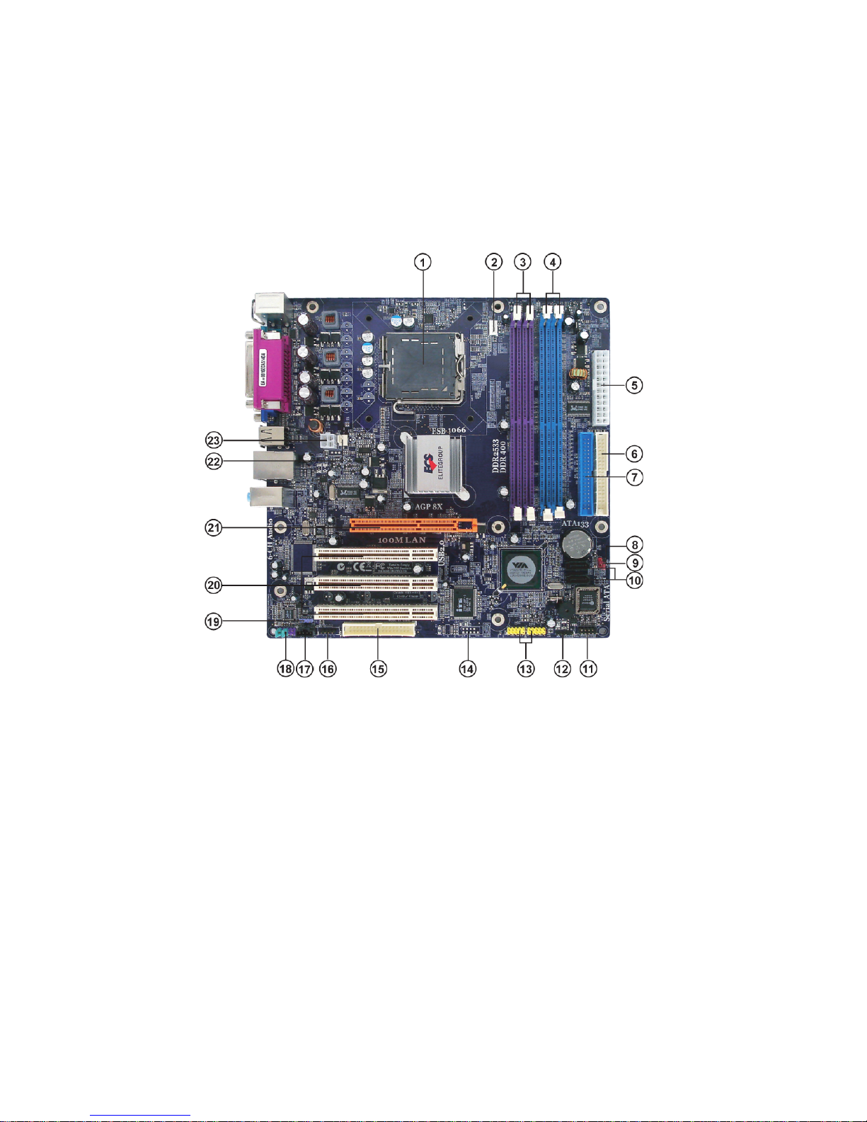
Motherboard Components
Introducing the Motherboard
Page 11

Table of Motherboard Components
LABEL COMPONENT
1 CPU Socket
2 CPU_FAN CPU cooling fan connector
3 DDRII1~2 240-pin DDR2 SDRAM slots
4 DDR1~2 184-pin DDR SDRAM slots
5 ATX1 Standard 24-pin ATX power connector
6 IDE1 Primary IDE channel
7 IDE2 Secondary IDE channel
8 BIOS_WP BIOS protect jumper
9 CLR_CMOS Clear CMOS jumper
10 SATA1~2 Serial ATA connectors
11 PANEL1 Front Panel switch/LED header
12 IRDA* Infrared header
13 USB3~4 Front Panel USB headers
14 COM2* Onboard serial port header
15 FDD Floppy diskette drive connector
16 AUX_IN* Auxiliary audio input header
1 7 CD_IN1 Analog audio input connector
18 AUDIO1 Front panel audio header
19 SPDIFO1* SPDIF out header
20 PCI1~3 32-bit add-on card slots
21 AGP1 Accelerated Graphics Port slot
22 SYS_FAN System cooling fan connector
23 ATX_12V1 4-pin +12V power connector
LGA775 socket for Intel® Core™2 Duo/
Pentium D/Pentium 4/Celeron D CPUs
* Stands for optional components
5
Users please note that DDR & DDR2 can’t both be applied at the same time on this
motherboard. Users can use either DDR or DDR2 memory modules only!
This concludes Chapter 1. The next chapter explains how to install the motherboard.
Introducing the Motherboard
Page 12

6
Memo
Introducing the Motherboard
Page 13

Chapter 2
Installing the Motherboard
Safety Precautions
• Follow these safety precautions when installing the motherboard
• Wear a grounding strap attached to a grounded device to avoid damage from
static electricity
• Discharge static electricity by touching the metal case of a safely grounded
object before working on the motherboard
• Leave components in the static-proof bags they came in
• Hold all circuit boards by the edges. Do not bend circuit boards
Choosing a Computer Case
There are many types of computer cases on the market. The motherboard complies with
the specifications for the Micro ATX system case. First, some features on the motherboard
are implemented by cabling connectors on the motherboard to indicators and switches on
the system case. Make sure that your case supports all the features required. Secondly, this
motherboard supports one or two floppy diskette drives and four enhanced IDE drives.
Make sure that your case has sufficient power and space for all drives that you intend to
install.
Most cases have a choice of I/O templates in the rear panel. Make sure that the I/O
template in the case matches the I/O ports installed on the rear edge of the motherboard.
This motherboard carries a Micro ATX form factor of 244 x 244 mm. Choose a case that
accommodates this form factor.
7
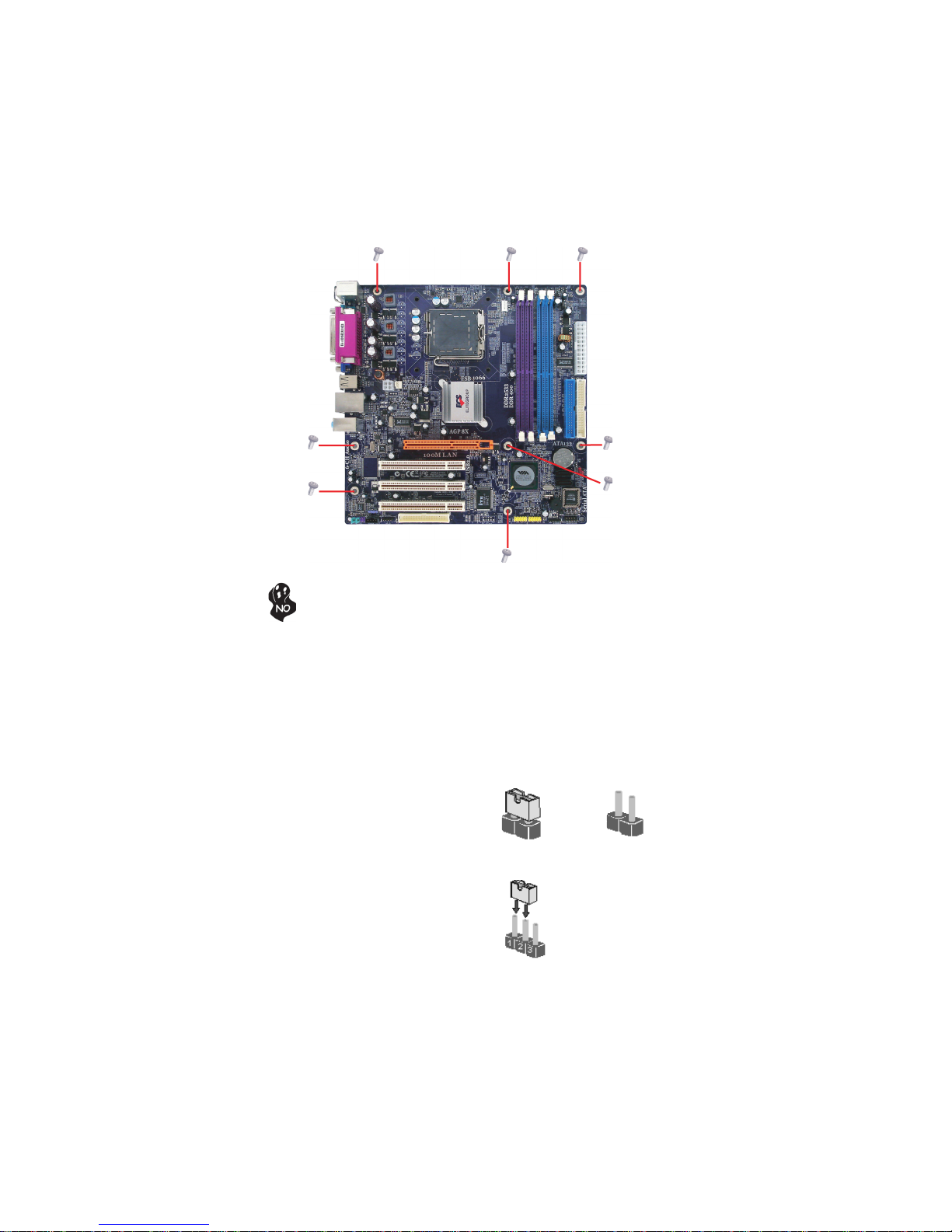
Installing the Motherboard in a Case
Refer to the following illustration and instructions for installing the motherboard in a case.
Most system cases have mounting brackets installed in the case, which correspond the holes
in the motherboard. Place the motherboard over the mounting brackets and secure the
motherboard onto the mounting brackets with screws.
Ensure that your case has an I/O template that supports the I/O ports and expansion slots
on your motherboard.
Installing the Motherboard
Page 14
8
Do not over-tighten the screws as this can stress the motherboard.
Checking Jumper Settings
This section explains how to set jumpers for correct configuration of the motherboard.
Setting Jumpers
Use the motherboard jumpers to set system configuration options. Jumpers with more than
one pin are numbered. When setting the jumpers, ensure that the jumper caps are placed on
the correct pins.
The illustrations show a 2-pin jumper. When
the jumper cap is placed on both pins, the
jumper is SHORT. If you remove the jumper
cap, or place the jumper cap on just one pin,
the jumper is OPEN.
This illustration shows a 3-pin jumper. Pins
1 and 2 are SHORT
SHORT OPEN
Installing the Motherboard
Page 15
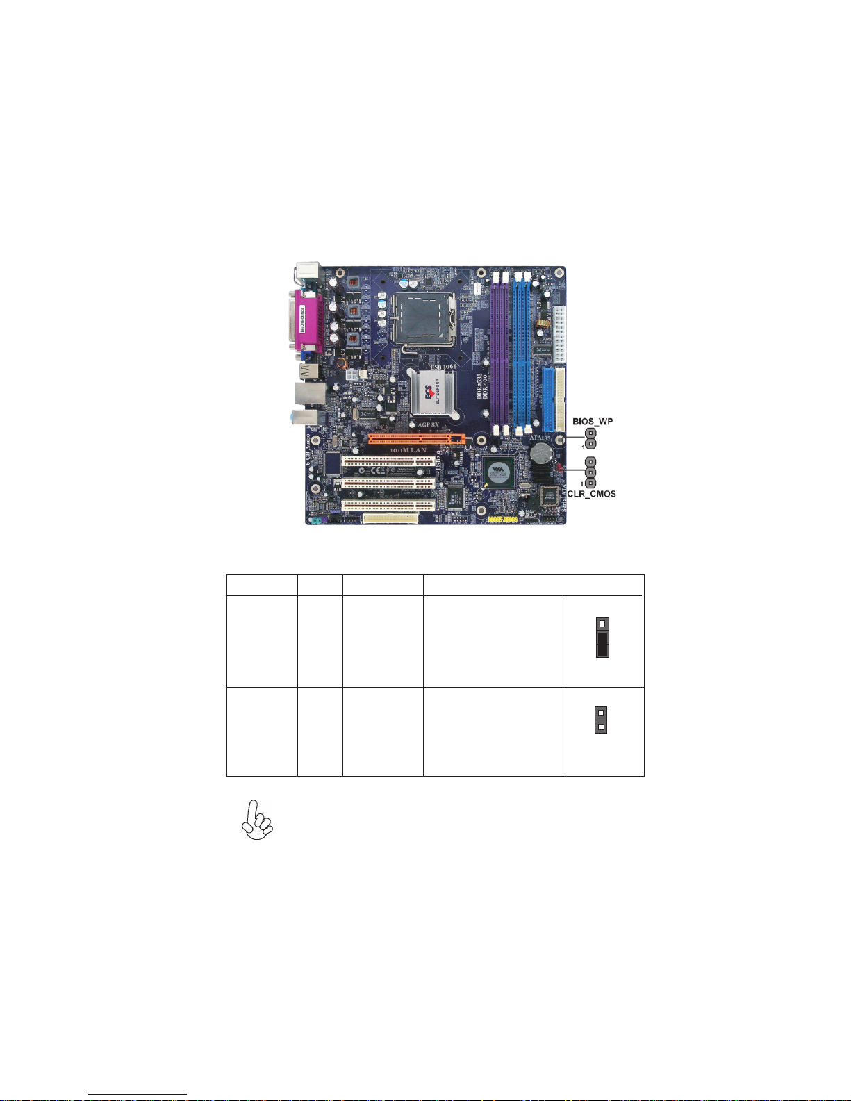
Checking Jumper Settings
The following illustration shows the location of the motherboard jumpers. Pin 1 is labeled.
Jumper Settings
9
Jumper
CLR_CMOS
BIOS_WP
Type
3-pin
2-pin
To avoid the system unstability after clearing CMOS, we recommend
users to enter the main BIOS setting page to “Load Optimal Defaults”
and then “Save Changes and Exit”.
Description
Clear CMOS
BIOS_WP
Setting (default)
1-2: NORMAL
2-3: CLEAR
Before clearing the
CMOS, make sure to
turn off the system.
OPEN: DISABLE
SHORT: ENABLE
1
CLR_CMOS
1
BIOS_WP
Installing the Motherboard
Page 16
10
Connecting Case Components
After you have installed the motherboard into a case, you can begin connecting the motherboard components. Refer to the following:
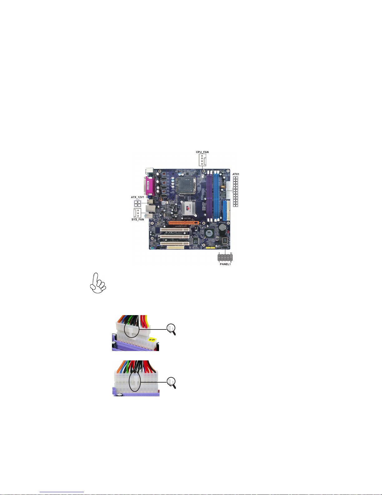
1 Connect the CPU cooling fan cable to CPU_FAN.
2 Connect the system cooling fan connector to SYS_FAN.
3 Connect the case switches and indicator LEDs to the PANEL1.
4 Connect the standard power supply connector to ATX1.
5 Connect the auxiliary case power supply connector to ATX_12V1.
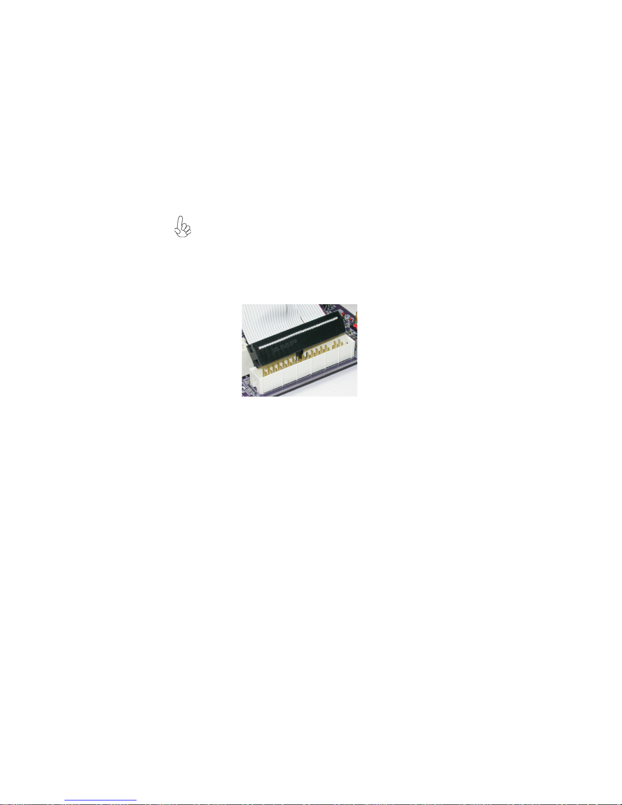
Connecting 20/24-pin power cable
Users please note that the 20-pin and 24-pin power cables can both be connected to the ATX1 connector. With the 20-pin power cable, just align the 20pin power cable with the pin 1 of the ATX1 connector. However, using 20-pin
power cable may cause the system to become unbootable or unstable because of
insufficient electricity. A minimum power of 300W is recommended for a fullyconfigured system.
With ATX v1.x power supply, users please
note that when installing 20-pin power cable,
the latche of power cable clings to the left
side of the ATX1 connector latch, just as the
20-pin power cable
24-pin power cable
picture shows.
With ATX v2.x power supply, users please
note that when installing 24-pin power cable,
the latches of power cable clings to the right
side of the ATX1 connector latch.
Installing the Motherboard
Page 17
CPU_FAN: CPU FAN Power Connector
Pin Signal Name Function
1 GND System Ground
2 +12V Power +12V
3 Sense Sensor
4 PWM CPU FAN control
Users please note that the fan connector supports the CPU cooling
fan of 1.1A~2.2A (26.4W max.) at +12V.
SYS_FAN: System cooling FAN Power Connector
Pin Signal Name Function
1 GND System Ground
2 +12V Power +12V
3 Sense Sensor
ATX_12V1: ATX 12V Power Connector
Pin Signal Name
1 Ground
2 Ground
3 +12V
4 +12V
11
ATX1: ATX 24-pin Power Connector
Pin Signal Name Pin Signal Name
1 +3.3V 13 +3.3V
2 +3.3V 14 -12V
3 Ground 15 Ground
4 +5V 16 PS_ON
5 Ground 17 Ground
6 +5V 18 Ground
7 Ground 19 Ground
8 PWRGD 20 -5V
9 +5VSB 21 +5V
10 +12V 22 +5V
11 +12V 23 +5V
12 +3.3V 24 Ground
Installing the Motherboard
Page 18
12
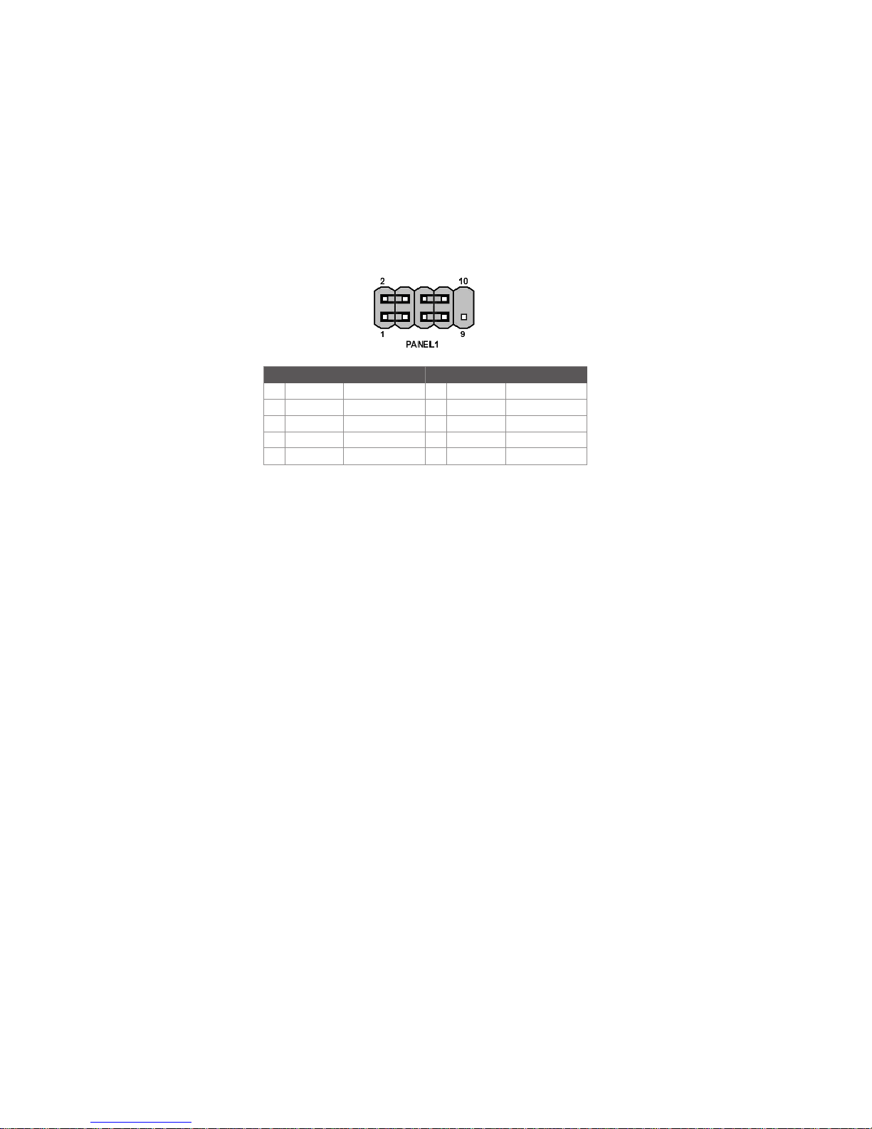
Front Panel header
The front panel header (PANEL1) provides a standard set of switch and LED headers
commonly found on ATX or micro-ATX cases. Refer to the table below for information:
Pin Signal Function Pin Signal Function
1 HD_LED_P Hard disk LED(+)
3 HD_LED_N Hard disk LED(-)
5 RST_SW_N Reset Switch(-)
7 RST_SW_P Reset Switch(+)
9 RSVD Reserved
* MSG LED (dual color or single color)
Hard Drive Activity LED
Connecting pins 1 and 3 to a front panel mounted LED provides visual indication that data
is being read from or written to the hard drive. For the LED to function properly, an IDE
drive should be connected to the onboard IDE interface. The LED will also show activity
for devices connected to the SCSI (hard drive activity LED) connector.
2 FP PWR/SLP *MSG LED(+)
4 FP PWR/SLP *MSG LED(-)
6 PWR_SW_P Power Switch(+)
8 PWR_SW_N Power Switch(-)
10 Key No pin
Power/Sleep/Message waiting LED
Connecting pins 2 and 4 to a single or dual-color, front panel mounted LED provides power
on/off, sleep, and message waiting indication.
Reset Switch
Supporting the reset function requires connecting pin 5 and 7 to a momentary-contact
switch that is normally open. When the switch is closed, the board resets and runs POST.
Power Switch
Supporting the power on/off function requires connecting pins 6 and 8 to a momentarycontact switch that is normally open. The switch should maintain contact for at least 50 ms
to signal the power supply to switch on or off. The time requirement is due to internal debounce circuitry. After receiving a power on/off signal, at least two seconds elapses before
the power supply recognizes another on/off signal.
Installing the Motherboard
Page 19

Installing Hardware
Installing the Processor
Caution: When installing a CPU heatsink and cooling fan make sure that
you DO NOT scratch the motherboard or any of the surface-mount resistors
with the clip of the cooling fan. If the clip of the cooling fan scrapes across
the motherboard, you may cause serious damage to the motherboard or its
components.
On most motherboards, there are small surface-mount resistors near the
processor socket, which may be damaged if the cooling fan is carelessly
installed.
Avoid using cooling fans with sharp edges on the fan casing and the clips.
Also, install the cooling fan in a well-lit work area so that you can clearly see
the motherboard and processor socket.
Before installing the Processor
This motherboard automatically determines the CPU clock frequency and system bus
frequency for the processor. You may be able to change these settings by making changes
to jumpers on the motherboard, or changing the settings in the system Setup Utility. We
strongly recommend that you do not over-clock processors or other components to run
faster than their rated speed.
Warning: Over-clocking components can adversely affect the reliability
of the system and introduce errors into your system. Over-clocking can
permanently damage the motherboard by generating excess heat in
components that are run beyond the rated limits.
13
This motherboard has an LGA 775 socket. When choosing a processor, consider the
performance requirements of the system. Performance is based on the processor design, the
clock speed and system bus frequency of the processor, and the quantity of internal cache
memory and external cache memory.
Installing the Motherboard
Page 20
14
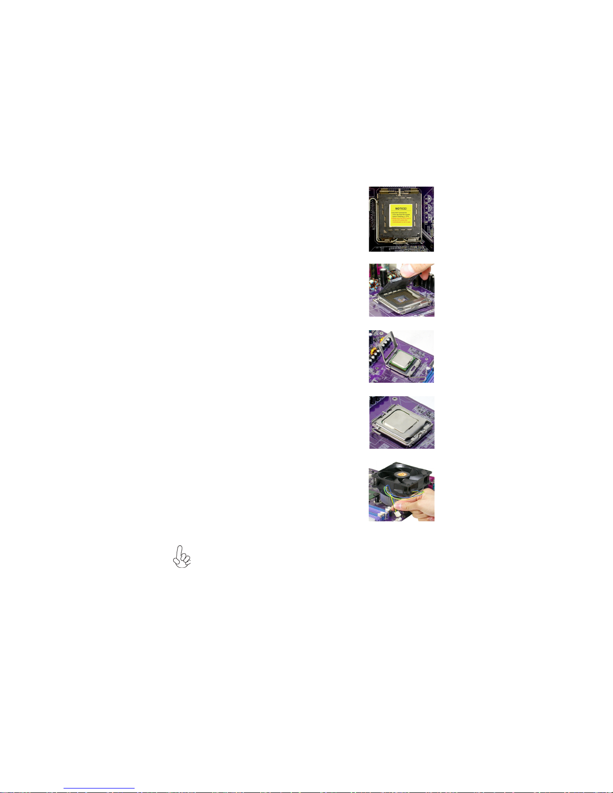
CPU Installation Procedure
The following illustration shows CPU installation components.
A. Read and follow the instructions shown on
the sticker on the CPU cap.
B. Unload the cap
· Use thumb & forefinger to hold the
lifting tab of the cap.
· Lift the cap up and remove the cap
completely from the socket.
C Open the load plate
· Use thumb & forefinger to hold the
hook of the lever, pushing down and pulling
aside unlock it.
· Lift up the lever.
· Use thumb to open the load plate. Be
careful not to touch the contacts.
D. Install the CPU on the socket
· Orientate CPU package to the socket.
Make sure you match triangle marker
to pin 1 location.
E. Close the load plate
· Slightly push down the load plate onto the
tongue side, and hook the lever.
· CPU is locked completely.
F. Apply thermal grease on top of the CPU.
G. Fasten the cooling fan supporting base onto
the CPU socket on the motherboard.
H. Make sure the CPU fan is plugged to the
CPU fan connector. Please refer to the CPU
cooling fan user’s manual for more detail
installation procedure.
1. To achieve better airflow rates and heat dissipation, we suggest that you
use a high quality fan with 3800 rpm at least. CPU fan and heatsink
installation procedures may vary with the type of CPU fan/heatsink supplied. The form and size of fan/heatsink may also vary.
2. DO NOT remove the CPU cap from the socket before installing a CPU.
3 . Return Material Authorization (RMA) requests will be accepted only if
the motherboard comes with the cap on the LGA775 socket.
Installing the Motherboard
Page 21
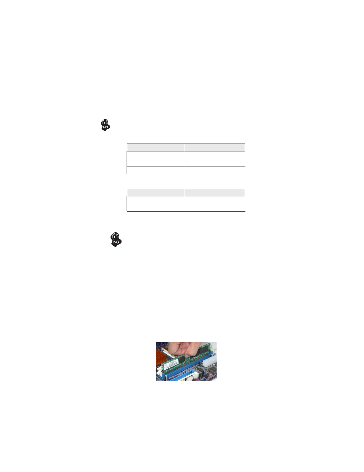
Installing Memory Modules
This motherboard accommodates four memory modules. It can support two 184-pin
unbuffered DIMMs, DDR 400/333/266 or two 240-pin DDR2 533/400. The total memory
support capacity is 2 GB.
Users please note that DDR & DDR2 can’t both be applied at the same time on
this motherboard. Users can use either DDR or DDR2 memory modules only!
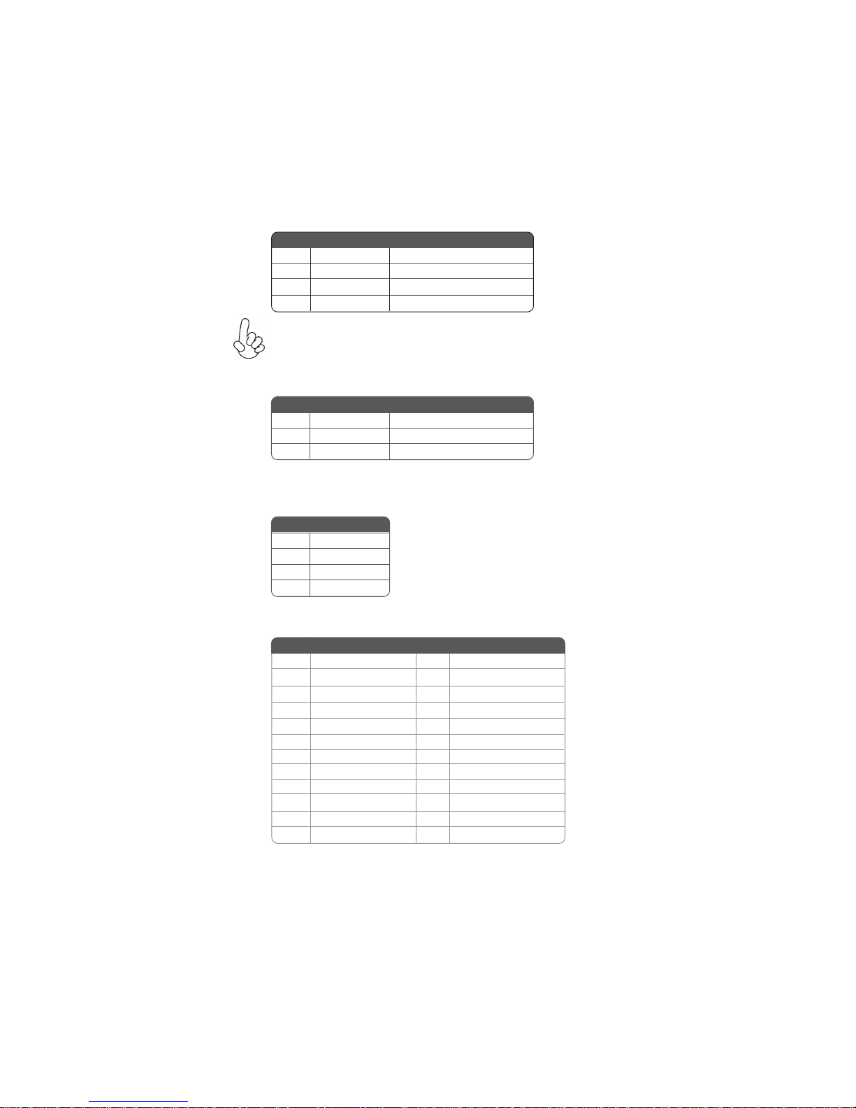
DDR SDRAM memory module table
Memory module Memory Bus
DDR 266 133 MHz
DDR 333 166 MHz
DDR 400 200 MHz
DDR2 SDRAM memory module table
Memory module Memory Bus
DDR2 400 200 MHz
DDR2 533 266 MHz
You must install at least one module in any of the four slots. Each module can be installed
with 256 MB to 1 GB of memory; total support memory capacity is 2 GB.
Do not remove any memory module from its antistatic packaging until you
are ready to install it on the motherboard. Handle the modules only by
their edges. Do not touch the components or metal parts. Always wear a
grounding strap when you handle the modules.
15
Installation Procedure
Refer to the following to install the memory modules.
1 This motherboard supports unbuffered DDR or DDR2 SDRAM .
2 Push the latches on each side of the DIMM slot down.
3 Align the memory module with the slot. The DIMM slots are keyed with
notches and the DIMMs are keyed with cutouts so that they can only be
installed correctly.
4 Check that the cutouts on the DIMM module edge connector match the notches
in the DIMM slot.
5 Install the DIMM module into the slot and press it firmly down until it seats
correctly. The slot latches are levered upwards and latch on to the edges of
the DIMM.
6 Install any remaining DIMM modules.
Installing the Motherboard
Page 22

16
Table A: DDR (memory module) QVL (Qualified Vendor List)
The following DDR400 memory modules have been tested and qualified for use with this
motherboard.
Size Vendor
APACER AM3A568ACT05A
CORSAIR PLATNUM CMX256-3200C2PT
GEIL G208L364D1TG5NKT3C
GEIL GE08L3264D1WL5NKT3H71
GEIL GL3L32G88TG-5A
Hynix HY5DU56822BT-D43
256 MB
Kingston Winbond W942508BH-5
Kingston Samsung K4H560838D-TCC4
Ramaxel Samsung K4H560838D-TCC4
Ramaxel MIC-R46V32M8TG-5BC
Samsung K4H560838D-TCCC
Samsung K4H560838E-TCCC
Soutec M2G9108AKAS09F083S9DT
CORSAIR PLATNUM CMX512-3200C2PT
GEIL GE16L6464D2WL5NKT3H66
512 MB
Hynix HY5DU56822BT-D43
Kingston Samsung K4H560838D-TCC4
Kingmax KDL388P4EA-50
Module Name
Installing the Motherboard
Page 23
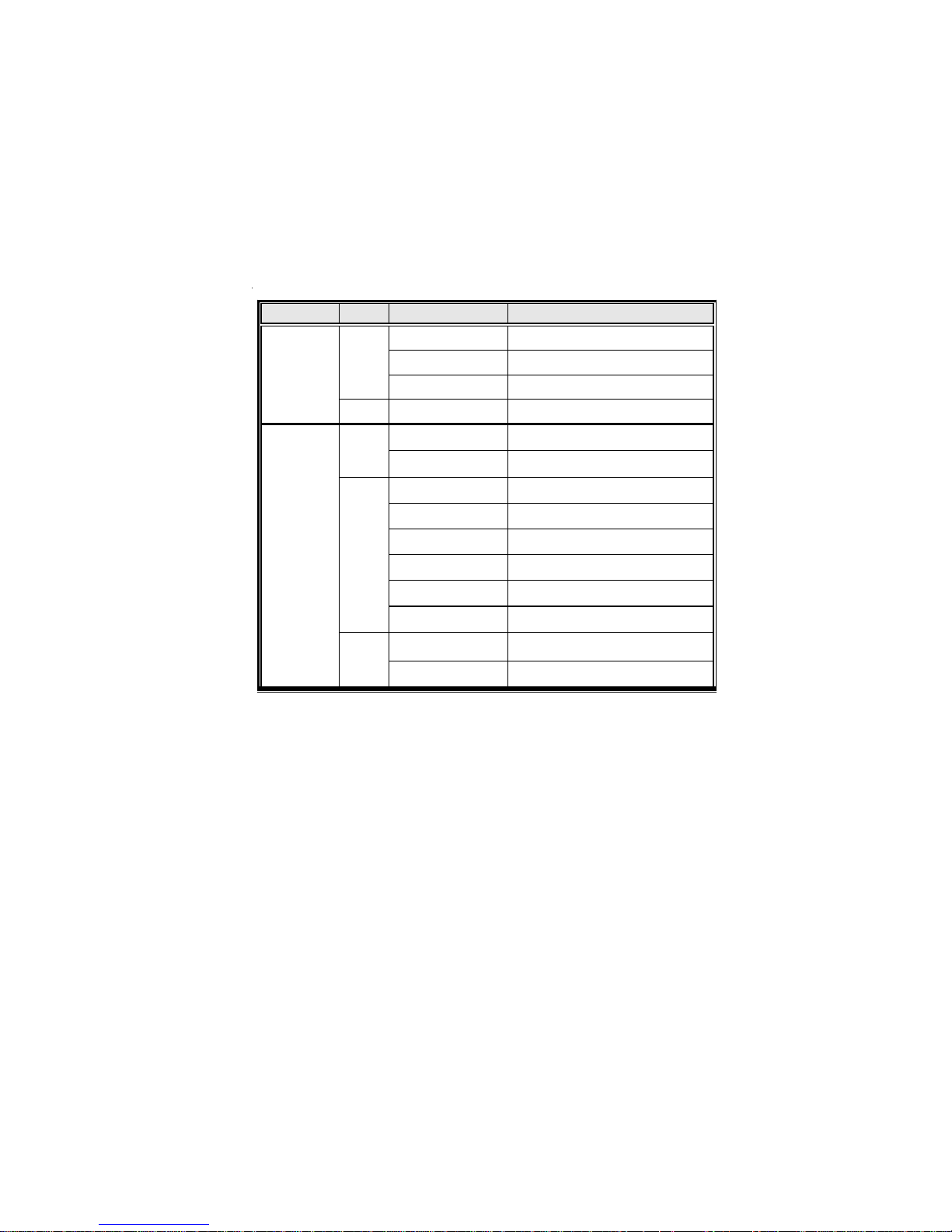
Table B: DDR2 (memory module) QVL (Qualified Vendor List)
The following DDR2 memory modules have been tested and qualified for use with this
motherboard.
Typ e Size Vendor Module Name
DDR2 400
DDR2 533
256 MB
512 MB
256 MB
512 MB
Hynix HYMP532U646-E3 AA
Nanya NT256T64UH4A0F-5A CL3
Samsung M378T3253FG0-CCC
Hynix HYMP564U648-E3 AA
Corsair 4PB11D9CHM
Eipida B04180WB00
Corsair 4PB11D9CHM
Eipida 04180WB01
Kingston HY5PS56821
Twinmos Elpida 8D22JB-ED
Twinmos Hynix 8D22JB-HX
Samsung K4T56083QF-ZCD5
17
1 GB
Kingston Infineon HYB18T51260AF-E
Installing the Motherboard
Apacer ELPIDA E5108AB-5C-E
Page 24
18
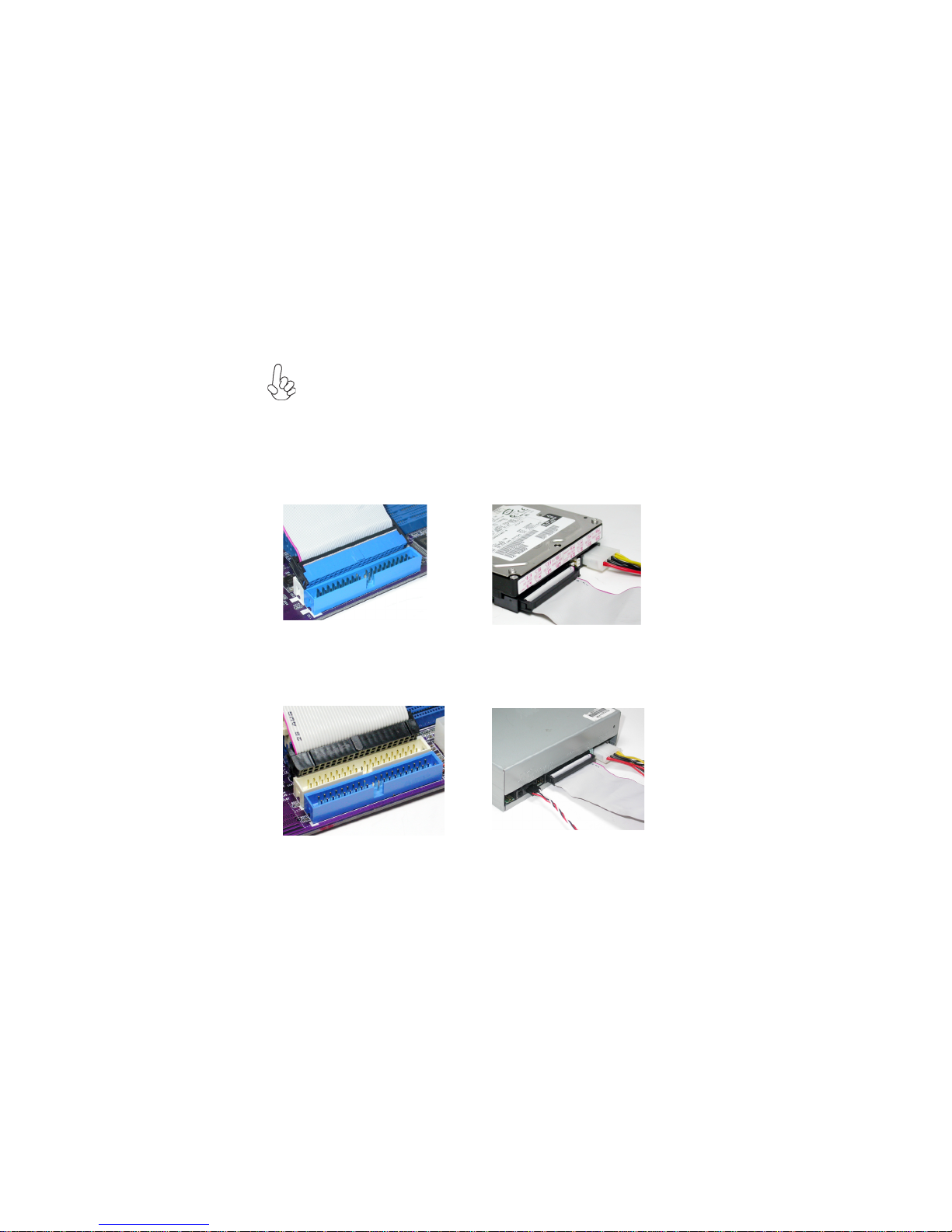
Installing a Hard Dish Drive/CD-ROM/SATA Hard Drive
This section describes how to install IDE devices such as a hard disk drive and a CD-ROM
drive.
About IDE Devices
Your motherboard has two IDE channels interface. An IDE ribbon cable supporting two IDE
devices is bundled with the motherboard.
You must orient the cable connector so that the pin1 (color) edge of the
cable corresponds to the pin 1 of the I/O port connector.
IDE1: IDE Connector
This motherboard supports two high data transfer SATA ports with each runs up to 1.5 Gb/
s. To get better system performance, we recommend users connect the CD-ROM to the
IDE channel, and set up the hard dives on the SATA ports.
IDE2: Secondary IDE Connector
The second drive on this controller must be set to slave mode. The cinfiguration is the same
as IDE1.
IDE devices enclose jumpers or switches used to set the IDE device as MASTER or SLAVE.
Refer to the IDE device user’s manual. Installing two IDE devices on one cable, ensure that
one device is set to MASTER and the other device is set to SLAVE. The documentation of
your IDE device explains how to do this.
Installing the Motherboard
Page 25
About SATA Connectors
Your motherboard features two SATA connectors supporting a total of two drives. SATA , or
Serial ATA (Advanced Technology Attachment) is the standard interface for the IDE hard
drives which are currently used in most PCs. These connectors are well designed and will
only fit in one orientation. Locate the SATA connectors on the motherboard and follow the
illustration below to install the SATA hard drives.
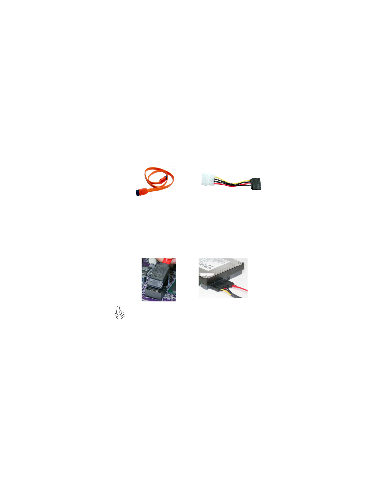
Installing Serial ATA Hard Drives
To install the Serial ATA (SATA) hard drives, use the SATA cable that supports the Serial
ATA protocol. This SATA cable comes with an SATA power cable. You can connect either
end of the SATA cable to the SATA hard drive or the connector on the motherboard.
19
SATA cable (optional)
Refer to the illustration below for proper installation:
1 Attach either cable end to the connector on the motherboard.
2 Attach the other cable end to the SATA hard drive.
3 Attach the SATA power cable to the SATA hard drive and connect the other
end to the power supply.
This motherboard does not support the “Hot-Plug” function.
SATA power cable (optional)
Installing the Motherboard
Page 26
20
Installing a Floppy Diskette Drive
The motherboard has a floppy diskette drive (FDD) interface and ships with a diskette drive
ribbon cable that supports one or two floppy diskette drives. You can install a 5.25-inch
drive and a 3.5-inch drive with various capacities. The floppy diskette drive cable has one
type of connector for a 5.25-inch drive and another type of connector for a 3.5-inch drive.
You must orient the cable connector so that the pin 1 (color) edge of the
cable corresponds to the pin 1 of the I/O port connector.
FDD: Floppy Disk Connector
This connector supports the provided floppy drive ribbon cable. After connecting the single
end to the onboard floppy connector, connect the remaining plugs on the other end to the
floppy drives correspondingly.
Installing the Motherboard
Page 27
Installing Add-on Cards
The slots on this motherboard are designed to hold expansion cards and connect them to the
system bus. Expansion slots are a means of adding or enhancing the motherboard’s features
and capabilities. With these efficient facilities, you can increase the motherboard’s capabilities by adding hardware that performs tasks that are not part of the basic system.
21
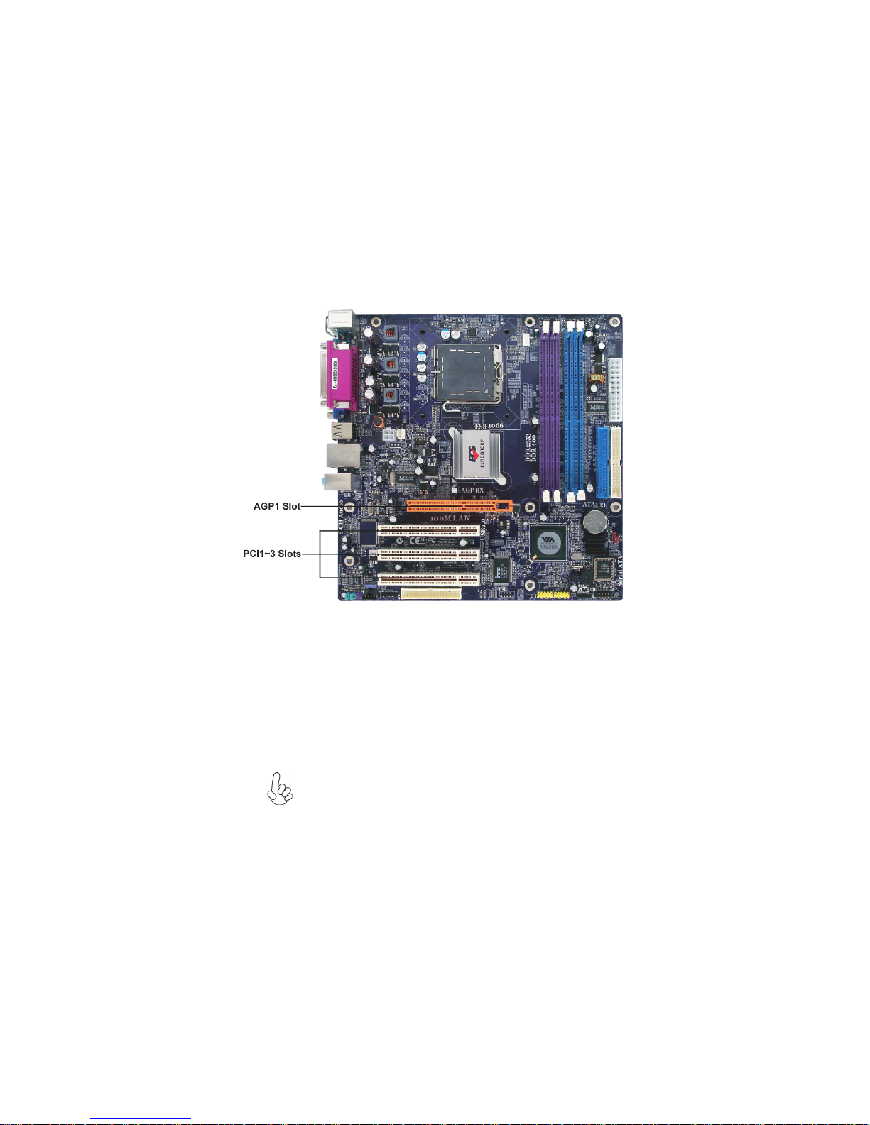
AGP1 Slot
PCI1~3 Slots
The AGP slot is used to install a graphics adapter that supports the 8X/4X
AGP specification. It is AGP 3.0 compliant.
This motherboard is equipped with three standard PCI slots. PCI stands for
Peripheral Component Interconnect and is a bus standard for expansion
cards, which for the most part, is a supplement of the older ISA bus standard. The PCI slots on this board are PCI v2.2 compliant.
Before installing an add-on card, check the documentation for the card
carefully. If the card is not Plug and Play, you may have to manually
configure the card before installation.
Installing the Motherboard
Page 28
22
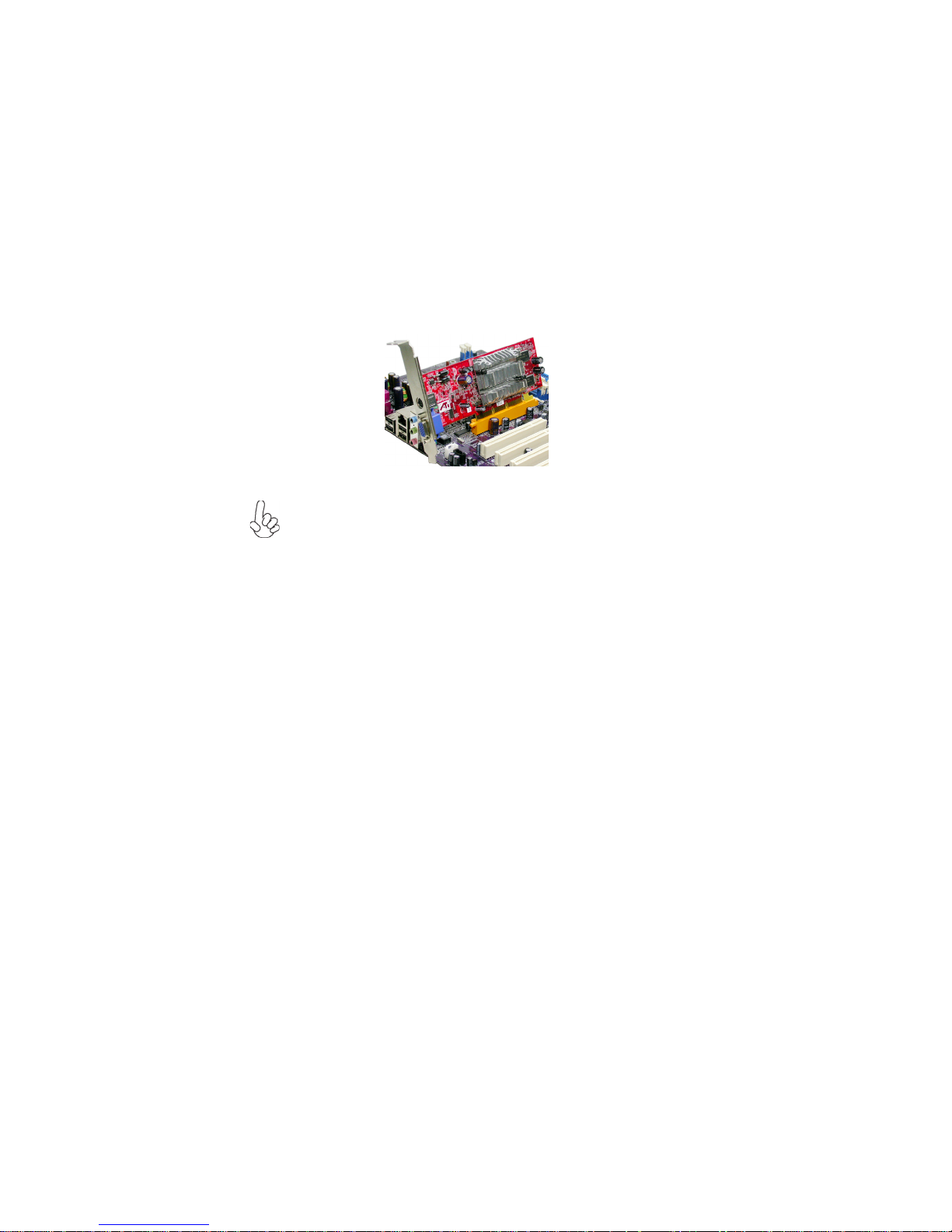
Follow these instructions to install an add-on card:
1 Remove a blanking plate from the system case corresponding to the slot you
are going to use.
2 Install the edge connector of the add-on card into the expansion slot. Ensure
that the edge connector is correctly seated in the slot.
3 Secure the metal bracket of the card to the system case with a screw.
For some add-on cards, for example graphics adapters and network adapters,
you have to install drivers and software before you can begin using the add-on
card.
Installing the Motherboard
Page 29

Connecting Optional Devices
Refer to the following for information on connecting the motherboard’s optional devices:
23
USB3~4: Front Panel USB headers
The motherboard has four USB ports installed on the rear edge I/O port array. Additionally,
some computer cases have USB ports at the front of the case. If you have this kind of case,
use auxiliary USB connector to connect the front-mounted ports to the motherboard.
Pin Signal Name Function
1 USBPWR Front Panel USB Power
2 USBPWR Front Panel USB Power
3 USB_F P_P0 (-) USB Port 0 Negative Signal
4 USB_FP_P1 (-) USB Port 1 Negative Signal
5 USB_FP_P0 (+) USB Port 0 Positive Signal
6 USB_FP_P1 (+) USB Port 1 Positive Signal
7 GND Ground
8 GND Ground
9 Key No pin
10 USB_FP_OC0 Overcurrent signal
Installing the Motherboard
Page 30

24
AUDIO1: Front Panel Audio header
This header allows the user to install auxiliary front-oriented microphone and line-out ports
for easier access.
Pin Signal Name Function
1 AUD_MIC Front Panel Microphone input signal
2 AUD_GND Ground used by Analog Audio Circuits
3 AUD_MIC_BIAS Microphone Power
4 AUD_VCC Filtered +5V used by Analog Audio Circuits
5 AUD_F_R Right Channel audio signal to Front Panel
6 AUD_RET_R Right Channel Audio signal to Return from Front Panel
7 REVD Reserved
8 Key No Pin
9 AUD_F_L Left Channel Audio signal to Front Panel
10 AUD_RET_L Left Channel Audio signal to Return from Front Panel
If your front panel cable is seperated, please connect it to pin1 and pin3 or
pin5 and pin7 to activate the MIC function.
CD_IN1: Analog Audio Input connector
Pin Signal Name Function
1 CD in_L CD In left channel
2 GND Ground
3 GND Ground
4 CD in_R CD In right channel
SPDIFO1: SPDIF out header (Optional)
This is an optional header that provides an S/PDIF (Sony/Philips Digital Interface) output
to digital multimedia device through optical fiber or coxial connector.
Pin Signal Name
Pin Signal Name Function
1 SPDIF SPDIF digital output
2 +5VA 5V analog power
3 Key No pin
4 GND Ground
Function
AUX_IN: Auxiliary-in header (Optional)
This header is an additional line-in audio header. It allows you to attach a line-in cable when
your rear line-in jack is set as line out port for 4-channel function.
Pin Signal Name Function
1 AUXIN_L AUX In left channel
2 AGND Ground
3 AGND Ground
4 AUXIN_R AUX In right channel
Installing the Motherboard
Page 31

IRDA: Infrared header (Optional)
The motherboard supports an Infrared (IRDA) data port. Infrared ports allow the wireless
exchange of information between your computer and similarly equipped devices such as
printers, laptops, Personal Digital Assistants (PDAs), and other computers.
Pin Signal Name
1 VCC
Pin Description
2 No Pin
3 IRRX
4 Ground
5 IRTX
SATA1~2: Serial ATA connectors
These connectors are used to support the new Serial ATA devices for the highest date
transfer rates (1.5 Gb/s), simpler disk drive cabling and easier PC assembly. It eliminates
limitations of the current Parallel ATA interface. But maintains register compatibility and
software compatibility with Parallel ATA.
25
Pin Signal Name
Pin Signal Name Function
1 Ground 2 TX (+)
3 TX (-) 4 Ground
5 RX (-) 6 RX (+)
7 Ground - -
Pin Signal Name
COM2: Onboard serial port header (Optional)
Connect a serial port extension bracket to this header to add a second serial port to your
system.
Pin Signal Name Function
1 NDCDB Data carry detect
2 NSINB Serial Data In
3 NSOUTB Serail Data Out
4 NDTRB Data terminal ready
5 GND Ground
6 NDSRB Date set ready
7 NRTSB Request to send
8 NCTSB Clear to send
9 NRIB Ring Indicator
10 KEY Key
Installing the Motherboard
Page 32

26
Connecting I/O Devices
The backplane of the motherboard has the following I/O ports:
PS2 Mouse Use the upper PS/2 port to connect a PS/2 pointing device.
PS2 Keyboard Use the lower PS/2 port to connect a PS/2 keyboard.
Parallel Port (LPT1) Use LPT1 to connect printers or other parallel communications
devices.
Serial Port Use the COM port to connect serial devices such as mice or
(COM1) fax/modems.
LAN Port
(optional)
VGA Port Connect the monitor cable to the VGA port.
USB Ports Use the USB ports to connect USB devices.
Audio Ports
This concludes Chapter 2. The next chapter covers the BIOS.
Connect an RJ-45 jack to the LAN port to connect your computer
to the Network.
Use the three audio ports to connect audio devices. The first jack
is for stereo line-in signal. The second jack is for stereo line-out
signal. The third jack is for microphone.
Installing the Motherboard
Page 33

Chapter 3
Using BIOS
About the Setup Utility
The computer uses the latest American Megatrends BIOS with support for Windows Plug
and Play. The CMOS chip on the motherboard contains the ROM setup instructions for
configuring the motherboard BIOS.
The BIOS (Basic Input and Output System) Setup Utility displays the system’s configuration status and provides you with options to set system parameters. The parameters are
stored in battery-backed-up CMOS RAM that saves this information when the power is
turned off. When the system is turned back on, the system is configured with the values you
stored in CMOS.
The BIOS Setup Utility enables you to configure:
• Hard drives, diskette drives and peripherals
• Video display type and display options
• Password protection from unauthorized use
• Power Management features
The settings made in the Setup Utility affect how the computer performs. Before using the
Setup Utility, ensure that you understand the Setup Utility options.
27
This chapter provides explanations for Setup Utility options.
The Standard Configuration
A standard configuration has already been set in the Setup Utility. However, we recommend
that you read this chapter in case you need to make any changes in the future.
This Setup Utility should be used:
• when changing the system configuration
• when a configuration error is detected and you are prompted to make changes
to the Setup Utility
• when trying to resolve IRQ conflicts
• when making changes to the Power Management configuration
• when changing the password or making other changes to the Security Setup
Entering the Setup Utility
When you power on the system, BIOS enters the Power-On Self Test (POST) routines.
POST is a series of built-in diagnostics performed by the BIOS. After the POST routines are
completed, the following message appears:
Using BIOS
Page 34

28
↔
Press DEL/F1 to enter SETUP
Press the delete key or F1 to access the BIOS Setup Utility.
CMOS Setup Utility -- Copyright (C) 1985-2005, American Megatrends, Inc.
Standard CMOS Setup
Advanced Setup Hardware Monitor
Features Setup Load Optimal Defaults
Power Management Features Save Changes and Exit
PCI / Plug and Play Setup Discard Changes and Exit
BIOS Security Features
: Move
Enter : Select
↔
F1:General Help
Standard CMOS setup for changing time, date, hard disk type, etc.
v02.59 (C)Copyright 1985-2005, American Mega trends, Inc.
+/-/: Value
F9: Optimized Defaults
BIOS Navigation Keys
The BIOS navigation keys are listed below:
KEY FUNCTION
ESC Exits the current menu
< >
+/-/PU/PD Modifies the selected field’s values
F1 Displays a screen that describes all key functions
F9 Loads an optimized setting for better performance
F10 Saves the current configuration and exits setup
ESC Exits the current menu
Scrolls through the items on a menu
CPU PnP Setup
F10: Save
ESC: Exit
Using BIOS
Page 35

Updating the BIOS
You can download and install updated BIOS for this motherboard from the manufacturer’s
Web site. New BIOS provides support for new peripherals, improvements in performance,
or fixes for known bugs. Install new BIOS as follows:
1 If your motherboard has a BIOS protection jumper, change the setting to allow
BIOS flashing.
2 If your motherboard has an item called Firmware Write Protect in Advanced
BIOS features, disable it. (Firmware Write Protect prevents BIOS from being
overwritten.
3 Create a bootable system disk. (Refer to Windows online help for information
on creating a bootable system disk.)
4 Download the Flash Utility and new BIOS file from the manufacturer’s Web
site. Copy these files to the system diskette you created in Step 3.
5 Turn off your computer and insert the system diskette in your computer’s
diskette drive. (You might need to run the Setup Utility and change the boot
priority items on the Advanced BIOS Features Setup page, to force your
computer to boot from the floppy diskette drive first.)
6 At the A:\ prompt, type the Flash Utility program name and the filename of the
new bios and then press <Enter>. Example: AMINF340.EXE 040706.ROM
7 When the installation is complete, remove the floppy diskette from the diskette
drive and restart your computer. If your motherboard has a Flash BIOS jumper,
reset the jumper to protect the newly installed BIOS from being overwritten.
The computer will restart automatically.
Using BIOS
When you start the Setup Utility, the main menu appears. The main menu of the Setup
Utility displays a list of the options that are available. A highlight indicates which option is
currently selected. Use the cursor arrow keys to move the highlight to other options. When
an option is highlighted, execute the option by pressing <Enter>.
29
Some options lead to pop-up dialog boxes that prompt you to verify that you wish to
execute that option. Other options lead to dialog boxes that prompt you for information.
Some options (marked with a triangle
values for the option. Use the cursor arrow keys to scroll through the items in the submenu.
In this manual, default values are enclosed in parenthesis. Submenu items are denoted by a
triangle
.
) lead to submenus that enable you to change the
Using BIOS
Page 36

30
Standard CMOS Setup
This option displays basic information about your system.
CMOS Setup Utility - Copyright (C) 1985-2005, American Megatrends, Inc.
System Time 00: 01: 16
System Date Wed 08/23/2006
Primary IDE Master Hard Disk
Primary IDE Slave Not Detected
Secondary IDE Master Not Detected
Secondary IDE Slave Not Detected
SATA1 Not Detected
SATA2 Not Detected
Floppy A 1..44 MB 31/2”
Standard CMOS Setup
Help Item
Use [ENTER], [TAB]
or [SHIFT-TAB] TO
select a field.
Use [+] or [-] to
configure system Time.
< >
: Move
F1:General Help
Enter : Select
+/-/: Value
F9: Optimized Defaults
F10: Save
ESC: Exit
System Date and Time
The Date and Time items show the current date and time on the computer. If
you are running a Windows OS, these items are automatically updated whenever you make
changes to the Windows Date and Time Properties utility.
Primary/Secondary IDE Master/Slave, SATA1~2
Your computer has one IDE channel and each channel can be installed with one or two
devices (Master and Slave). In addition, this motherboard supports two SATA channels and
each channel allows one SATA device to be installed. Use these items to configure each
device on the IDE channel.
Floppy A
This item sets up size and capacity of the floppy diskette drive(s) installed in the system.
Press <Esc> to return to the main menu setting page.
Advanced Setup
This page sets up more advanced information about your system. Handle this page with
caution. Any changes can affect the operation of your computer.
CMOS Setup Utility - Copyright (C) 1985-2005, American Megatrends, Inc.
Quick Boot Enabled
1st Boot Device 1st FLOPPY DRIVE
2nd Boot Device Maxtor 6Y120P0
3rd Boot Device CD/DVD
Try Other Boot Device Yes
Bootup Num-Lock On
Aperture Size Select 64MB
DRAM Timing Auto
Auto Detect DIMM/PCI Clk Enabled
Spread Spectrum Enabled
Max CPUID Value Limit Disabled
Execute Disable Bit Disabled
CPU TM function Disabled
TM Status Disabled
C1E Support Disabled
Intel (R) SpeedStep (tm) tech. Disabled
Vanderpool Technology: Enabled
BIOS Protect Disabled
< >
F1:General Help
Advanced Setup
: Move
Enter : Select
+/-/: Value
F9: Optimized Defaults
F10: Save
Help Item
Allows BIOS to skip
certain tests while
booting. This will
decrease the time
needed to boot the
system.
ESC: Exit
Using BIOS
Page 37

Quick Boot (Enabled)
If you enable this item, the system starts up more quickly because of the elimination of
some of the power on test rutines.
1st/2nd/rd Boot Device
Use this item to determine the device order the computer used to look for an operating
system to load at start-up time. The devices showed here will be different depending on the
exact devices installed on your motherboard.
Try Other Boot Device (Yes)
If you enable this item, the system will also search for other boot devices if it fails to find
an operating system from the first boot device.
BootUp Num-Lock (On)
This item determines if the Num Lock key is active or inactive at system start-up time.
Aperture Size Select (64MB)
This item defines the size of aperture if you use a graphic adapter.
DRAM Timing (Auto)
This item allows you to enable or disable the DRAM timing defined by the Serial Presence
Detect electrical. Users please note that if setting this item to auto, the following two items
are not available.
Auto Detect DIMM/PCI Clk (Enabled)
When this item is enabled, BIOS will disable the clock signal of free DIMM/PCI slots.
Spread Spectrum (Enabled)
If you enable spread spertrum, it can significantly reduce the EMI (Electro-Magnetic
interface) generated by the system.
Max CPUID Value Limit (Disabled)
This item enables or disables the Max CPU ID value limit. When Prescott with LGA775
CPU is installed, enable this item to prevent the system from “rebooting” when trying to
install Windows NT4.0.
Execute Disabled Bit (Disabled)
Users please leave this item in its default setting under Windows XP OS. Change the value
to “Disabled” if users are to install Linux OS.
CPU TM function (Disabled)
This item displays CPU’s temperature and enables you to set a safe temperature to Prescoot
CPU.
TM Status (Disabled)
This item shows TM function status if CPU can support TM function.
31
C1E Support (Enabled)
This item enables or disables the CPU C1E function.
Intel (R) SpeedStep (tm) Tech. (Disabled)
This item enables or disables the Intel (R) SpeedStep (tm) technology. When enabled, allows
enhance Intel SpeedStep Technology transitions.
Using BIOS
Page 38

32
Vanderpool Technology (Enabled)
This item enables or disables the Vanderpool Technology. When disabled, forcess the VT
function will close.
BIOS Protect (Disabled)
This item enables or disables the BIOS protection function.
Press <Esc> to return to the main menu setting page.
Features Setup
This page sets up some parameters for peripheral devices connected to the system.
CMOS Setup Utility - Copyright (C) 1985-2005, American Megatrends, Inc.
OnBoard Floppy Controller Enabled
Serial Port1 Address 3F8/IRQ4
Serial Port1 Mode Normal
Parallel Port Address 378
Parallel Port Mode ECP
ECP Mode DMA Channel DMA3
Parallel Port IRQ IRQ7
OnBoard PCI IDE Controller Both
OnBoard SATA-IDE IDE
Audio Device Enabled
Modem Device Auto
Onboard LAN Enabled
Onboard LAN Boot ROM Disabled
Onboard USB Function Enabled
USB Function For DOS Enabled
< >
F1:General Help
Features Setup
Enter : Select
: Move
+/-/: Value
F9: Optimized Defaults
F10: Save
Help Item
Allow BIOS to Enable or
Disable Floppy Controller.
ESC: Exit
OnBoard Floppy Controller (Enabled)
Use this item to enable or disable the onboard floppy disk drive interface.
Serial Port1 Address (3F8/IRQ4)
Use this item to enable or disable the onboard COM1 serial port, and to assign a port address.
Serial Port1 Mode (Normal)
Use this item to select the onboard COM1 serial port mode.
Parallel Port Address (378)
Use this item to enable or disable the onboard Parallel port, and to assign a port address.
Parallel Port Mode (ECP)
Use this item to select the parallel port mode. You can select Normal (Standard Parallel
Port), ECP (Extended Capabilities Port), EPP (Enhanced Parallel Port), or BPP (BiDirectional Parallel Port).
Using BIOS
Page 39

ECP Mode DMA Channel (DMA3)
Use this item to assign the DMA Channel under ECP Mode function.
Parallel Port IRQ (IRQ7)
Use this item to assign IRQ to the parallel port.
OnBoard PCI IDE Controller (Both)
Use this item to enable or disable either or both of the onboard Primary and Secondary IDE
channels.
OnBoard SATA-IDE (IDE)
Use this item to set the onboard SATA-IDE channel to be disabled, IDE, or RAID.
Audio Device (Enabled)
Use this item to enable or disalbe the onboard audio device.
Modem Device (Auto)
Use this item to enable or disalbe the onboard MC’97 modem device.
Onboard LAN (Enabled)
Use this item to enable or disable the onboard LAN.
Onboard LAN Boot ROM (Disabled)
Use this item to enable or disable the boot function using the onboard LAN boot rom.
Onboard USB Function (Enabled)
Enable this item if you plan to use the USB ports on this motherboard.
USB Function For DOS (Enabled)
Enable this item if you plan to use the USB ports on this motherboard in a DOS environment.
33
Press <Esc> to return to the main menu setting page.
Using BIOS
Page 40

34
Power Mangement Features
This page sets up some parameters for system power management operation.
CMOS Setup Utility - Copyright (C) 1985-2005, American Megatrends, Inc.
Power Management Features
ACPI Aware O/S Yes
Power Management Enabled
ACPI Enhanced Efficiency Disabled
Suspend Time Out Disabled
Resume on RTC Alarm Disabled
Resume On Ring Disabled
Resume on PME# Disabled
Restore on AC/Power Loss Power Off
< >
F1:General Help
: Move
Enter : Select
+/-/: Value
F9: Optimized Defaults
F10: Save
Help Item
Enable/Disable
ACPI support for
Operating System.
ENABLE: If OS
supports ACPI.
DISABLE: If OS
does not support
ACPI.
ESC: Exit
ACPI Aware O/S (Yes)
This itme supports ACPI (Advanced Configuraion and Power Management Interface). Use
this item to enable or disable the ACPI feature.
Power Management (Enabled)
Use this item to enable or disable a power management scheme. If you enable power
management, you can use this item below to set the power management operation. Both
APM and ACPI are supported.
ACPI Enhanced Efficiency (Disabled)
This itme supports ACPI (Advanced Configuraion and Power Management Interface). Use
this item to enable or disable the ACPI enhanced efficiency feature.
Suspend Time Out (Disabled)
This item sets up the timeout for Suspend mode in minutes. If the time selected passes
without any system activity, the computer will enter power-saving Suspend mode.
Resume on RTC Alarm (Disabled)
The system can be turned off with a software command. If you enable this item, the system
can automatically resume at a fixed time based on the system’s RTC (realtime clock). Use
the items below this one to set the date and time of the wake-up alarm. You must use an ATX
power supply in order to use this feature.
Resume On Ring (Disabled)
The system can be turned off with a software command. If you enable this item, the system
can automatically resume if there is an incoming call on the Modem. You must use an ATX
power supply in order to use this feature.
Resume On PME# (Disabled)
The system can be turned off with a software command. If you enable this item, the system
can automatically resume if there is an incoming call on the PCI Modem or PCI LAN card.
You must use an ATX power supply in order to use this feature. Use this item to do wake-up
action if inserting the PCI card.
Using BIOS
Page 41

Restore on AC/Power Loss (Power Off)
This item defines how the system will act after AC power loss during system operation.
When you set to Off, it will keep the system in Off state until the power button is pressed.
Press <Esc> to return to the main menu setting page.
PCI / Plug and Play Setup
This page sets up some parameters for devices installed on the PCI bus and those utilizing
the system plug and play capability.
CMOS Setup Utility - Copyright (C) 1985-2005, American Megatrends, Inc.
PCI / Plug and Play Setup
35
Primary Graphics Adapter PCI
Share Memory Size 32 MB
Allocate IRQ to PCI VGA Yes
PCI IDE BusMaster Enabled
< >
F1:General Help
: Move
Enter : Select
+/-/: Value
F9: Optimized Defaults
F10: Save
Help Item
Options
PCI
AGP
ESC: Exit
Primary Graphics Adapter (PCI)
This itme indicates if the primary graphics adapter uses the PCI-E Lite VGA, PCI VGA, or
AGP.
Share Memory Size (32MB)
This itme lets you allocate a portion of the main memory for the onboard VGA display.
Allocate IRQ to PCI VGA (Yes)
If this item is enabled, an IRQ will be assigned to the PCI VGA graphics system. You set this
value to No to free up an IRQ.
PCI IDE BusMaster (Enabled)
This item enables or disabled the DMA under DOS mode. We recommend you to leave this
Press <Esc> to return to the main menu setting page.
Using BIOS
Page 42

36
BIOS Security Features
This page helps you install or change a password.
CMOS Setup Utility - Copyright (C) 1985-2005, American Megatrends, Inc.
BIOS Security Features
Security Settings
_____________________________________________________
Supervisor Password : Not Installed
Change Supervisor Password Press Enter
: Move
< >
F1:General Help
Enter : Select
+/-/: Value
F9: Optimized Defaults
F10: Save
Help item
Install or Change the
password.
ESC: Exit
Supervisor Password (Not Installed)
This item indicates whether a supervisor password has been set. If the password has benn
installed, Installed displays. If not, Not Installed displays.
Change Supervisor Password (Press Enter)
You can select this option and press <Enter> to access the sub menu. You can use the sub
menu to change the supervisor password.
Press <Esc> to return to the main menu setting page.
CPU PnP Setup
This page helps you manually configure the CPU of this motherborad. The system will
automatically detect the type of installed CPU and make the appropriate adjustments to
these items on this page.
CMOS Setup Utility - Copyright (C) 1985-2005, American Megatrends, Inc.
CPU PnP Setup
Manufacturer: Intel
Ratio Actual Value: 8
CPU Over-clocking Func. Disabled
CPU Frequency: 266MHz
DRAM Frequency Auto
Memory Voltage Normal
CPU Voltage Normal
AGP Voltage +0.05V
< >
F1:General Help
: Move
Enter : Select
+/-/: Value
F9: Optimized Defaults
Using BIOS
Options
Disabled
Enabled
F10: Save
Help Item
ESC: Exit
Page 43

Manufacturer (Intel)
This item indicates the brand of the CPU installed in your system.
Ratio Actual Value (8)
This item indicates the ratio actual value of the CPU installed in your system.
CPU Over-clocking Func. (Disabled)
This item decides the CPU over-clocking function/frequencyinstalled in your system. If the
over-clocking fails, please turn offthe system power. And then, hold the PageUp key
(similar to theClear CMOS function) and turn on the power, the BIOS willrecover the safe
default.
CPU Frequency (266MHz)
This item indicates the current CPU frequency. Users can not make any change to this item.
Please noted that the frequency will be varied with different CPU.
DRAM Frequency (Auto)
This item enables users to adjust the DRAM frequency. The default setting is auto and we
recommend users leave the setting unchanged. Modify it at will may cause the system to be
unstable.
Memory Voltage (Normal)
This item determines the DDR voltage adjustment.
CPU Voltage (Normal)
This item enables users to adjust the CPU voltage.
AGP Voltage (+0.05V)
This item determinese the AGP voltage adjustment.
37
Press <Esc> to return to the main menu setting page.
Hardware Monitor
This page helps you set up some parameters for the hardware monitoring function of this
motherboard.
CMOS Setup Utility - Copyright (C) 1985-2005, American Megatrends, Inc.
-=- System Hardware Monitor -=-
CPU Temperature : 37oC/98oF
SYSTEM Temperature : 29oC/84oF
CPU FAN Speed : 3040 RPM
SYSTEM FAN Speed : N /A
Vcore : 1.264 V
VIvdd : 3.328 V
Vdimm : 1.792 V
Vcc5V : 4.892 V
SB3V : 3.152 V
VBAT : 3.168 V
Shutdown Temp. Disabled
SMART Fan Control Disabled
< >
F1:General Help
Hardware Monitor
Enter : Select
: Move
+/-/: Value
F9: Optimized Defaults
F10: Save
Help Item
Options
Disabled
120°C/240°F
115°C/239°F
110°C/230°F
105°C/203°F
100°C/212°F
95°C/167°F
90°C/194°F
85°C/185°F
80°C/176°F
75°C/167°F
70°C/158°F
65°C/149°F
60°C/140°F
55°C/131°F
ESC: Exit
Using BIOS
Page 44

38
System Hardware Monitor
These items display the monitoring of the overall inboard hardware health events, such as
system&CPU temperature, CPU & DIMM voltage, CPU & system fan speed,...etc.
Shutdown Temperature (Disabled)
This item enables users to set the maximum temperature the system can reach before
powering down.
SMART Fan Control (Disabled)
This item enables users to enable or disable smart fan function.
Press <Esc> to return to the main menu setting page.
Load Optimal Defaults
This option opens a dialog box that lets you install stability-oriendted defaults for all
appropriate items in the Setup Utility. Select [OK] and then press <Enter> to install the
defaults. Select [Cancel] and then press <Enter> to not install the defaults.
Save Changes and Exit
Highlight this item and press <Enter> to save the changes that you have made in the Setup
Utility and exit the Setup Utility. When the Save and Exit dialog box appears, select [OK]
to save and exit, or select [Cancel] to return to the main menu.
Discard Changes and Exit
Highlight this item and press <Enter> to discard any changes that you have made in the
Setup Utility and exit the Setup Utility. When the Exit Without Saving dialog box appears,
select [OK] to discard changes and exit, or select [Cancel] to return to the main menu.
If you have made settings that you do not want to save, use the “Discard
Changes and Exit” item and select [OK] to discard any changes you have
made.
Using BIOS
Page 45

Chapter 4
Using the Motherboard Software
About the Software CD-ROM
The support software CD-ROM that is included in the motherboard package contains all the
drivers and utility programs needed to properly run the bundled products. Below you can find
a brief description of each software program, and the location for your motherboard
version. More information on some programs is available in a README file, located in the
same directory as the software.
Never try to install all software from folder that is not specified for use with
your motherboard.
Before installing any software, always inspect the folder for files named README.TXT,
INSTALL.TXT, or something similar. These files may contain important information that
is not included in this manual.
Auto-installing under Windows 98/ME/2000/XP
The Auto-install CD-ROM makes it easy for you to install the drivers and software for your
motherboard.
If the Auto-install CD-ROM does not work on your system, you can still install
drivers through the file manager for your OS (for example, Windows Explorer). Refer to the Utility Folder Installation Notes later in this chapter.
39
The support software CD-ROM disc loads automatically under Windows 98/ME/2000/XP.
When you insert the CD-ROM disc in the CD-ROM drive, the autorun feature will automatically bring up the install screen. The screen has three buttons on it, Setup, Browse CD and
Exit.
If the opening screen does not appear; double-click the file “setup.exe” in
the root directory.
Using the Motherboard Software
Page 46

40
Setup Tab
Setup
Browse CD
Exit The EXIT button closes the Auto Setup window.
Application Tab
Lists the software utilities that are available on the CD.
Read Me Tab
Displays the path for all software and drivers available on the CD.
Click the Setup button to run the software installation program. Select
from the menu which software you want to install.
The Browse CD button is the standard Windows command that allows
you to open Windows Explorer and show the contents of the support
CD.
Before installing the software from Windows Explorer, look for a file
named README.TXT, INSTALL.TXT or something similar. This file
may contain important information to help you install the software
correctly.
Some software is installed in separate folders for different operating
systems.
In installing the software, execute a file named SETUP.EXE or
INSTALL.EXE by double-clicking the file and then following the instructions on the screen.
Running Setup
Follow these instructions to install device drivers and software for the motherboard:
1. Click Setup. The installation program begins:
The following screens are examples only. The screens and driver lists will be
different according to the motherboard you are installing.
The motherboard identification is located in the upper left-hand corner.
Using the Motherboard Software
Page 47

2. Click Next. The following screen appears:
3. Check the box next to the items you want to install. The default options are recommended.
4. Click Next run the Installation Wizard. An item installation screen appears:
41
5. Follow the instructions on the screen to install the items.
Drivers and software are automatically installed in sequence. Follow the onscreen instructions, confirm commands and allow the computer to restart a few times to complete the
installation.
Using the Motherboard Software
Page 48

42
Manual Installation
Insert the CD in the CD-ROM drive and locate the PATH.DOC file in the root directory.
This file contains the information needed to locate the drivers for your motherboard.
Look for the chipset and motherboard model; then browse to the directory and path to
begin installing the drivers. Most drivers have a setup program (SETUP.EXE) that automatically detects your operating system before installation. Other drivers have the setup
program located in the operating system subfolder.
If the driver you want to install does not have a setup program, browse to the operating
system subfolder and locate the readme text file (README.TXT or README.DOC) for
information on installing the driver or software for your operating system.
Utility Software Reference
All the utility software available from this page is Windows compliant. They are provided
only for the convenience of the customer. The following software is furnished under license
and may only be used or copied in accordance with the terms of the license.
These software(s) are subject to change at anytime without prior notice.
Please refer to the support CD for available software.
This concludes Chapter 4.
Using the Motherboard Software
Page 49

Chapter 5
VIA VT8237 SATA RAID Setup Guide
VIA RAID Configurations
The motherboard includes a high performance Serial ATA RAID controller integrated in the
VIA VT8237 Southbridge chipset. It supports RAID 0, RAID 1 and JBOD with two independent Serial ATA channels.
RAID: (Redundant Array of Independent Disk Drives) use jointly several hard drives to
increase data transfer rates and data security. It depends on the number of drives present and
RAID function you select to fulfill the seurity or performance pruposes or both.
RAID 0 (called data striping) optimizes two identical hard disk drives to read and write data
in parallel, interleaved stacks. Two hard disks perform the same work as a single drive but at
a sustained data transfer rate, double that of a single disk alone, thus improving data access
and storage.
RAID 1 (called data mirroring) copies and maintains an identical image of data from one
drive to a second drive. If one drive fails, the disk array management software directs all
applications to the surviving drive as it contains a complete copy of the data in the other
drive. This RAID configuration provides data protection and increases fault tolerance to
the entire system.
JBOD: (Just a Bunch of Drives) Also known as “Spanning”. Two or more hard drives are
required. Several hard disk types configured as a single hard disk. The hard drives are simply
hooked up in series. This expands the capacity of your drive and results in a useable total
capacity. However, JBOD will not increase any performance or data security.
43
Install the Serial ATA (SATA) hard disks
The VIA VT8237 Southbridge chipset supports Serial ATA hard disk drives. For optimal
performance, install identical drives of the same model and capacity when creating a RAID
set.
• If you are creating a RAID 0 (striping) array of performance, use two new
drives.
• If you are creating a RAID 1 (mirroring) array for protection, you can use two
new drives or use an existing drive and a new drive (the new drive must be
of the same size or larger than the existing drive). If you use two drives of
different sizes, the smaller capacity hard disk will be the base storage size.
For example, one hard disk has an 80GB storage capacity and the other hard
disk has 60GB storage capacity, the maximum storage capacity for the RAID
Follow these steps to install the SATA hard disks for RAID configuration.
1 set is 60GB.
i Before setting up your new RAID array, verify the status of your hard disks.
Make sure the Master/Slave jumpers are configured properly.
ii Both the data and power SATA cables are new cables. You cannot use older
40-pin 80-conductor IDE or regular IDE power cables with Serial ATA drives.
Installing Serial ATA (SATA) hard disks require the use of new Serial ATA
cable (4-conductor) which supports the Serial ATA protocol and a Serial ATA
power cable.
VIA VT8237 SATA RAID Setup Guide
Page 50

44
iii Either end of the Serial ATA data cable can be connected to the SATA hard disk
or the SATA connector on the motherboard.
1 Install the Serial ATA hard disks into the drive bays.
2 Connect one end of the Serial ATA cable to the motherboard’s primary Serial
ATA connector (SATA1).
3 Connect the other end of Serial ATA cable to the master Serial ATA hard disk.
4 Connect one end of the second Serial ATA cable to the motherboard’s sec-
ondary Serial ATA connector (SATA2).
5 Connect the other end of Serial ATA cable to the secondary Serial ATA hard
disk.
6 Connect the Serial ATA power cable to the power connector on each drive.
7 Proceed to section “Entering VIA Tech RAID BIOS Utility” for the next proce-
dure.
Entering VIA Tech RAID BIOS Utility
1 Boot-up your computer.
2 During POST, press <TAB> to enter VIA RAID configuration utility. The follow-
ing menu options will appear.
The RAID BIOS information on the setup screen shown is for reference
only. What you see on your screen may not by exactly the same as shown.
On the upper-right side of the screen is the message and legend box. The keys on the legend
box allow you to navigate through the setup menu options. The message describes the
function of each menu item. The following lists the keys found in the legend box with their
corresponding functions.
F1 View Array
mn
Enter Confirm the selection
ESC Exit
Move to the next item
VIA VT8237 SATA RAID Setup Guide
Page 51

Create Array
1 In the VIA RAID BIOS utility main menu, select Create Array then press the
<Enter> key. The main menu items on the upper-left corner of the screen are
replaced with create array menu options.
RAID 0 for performance
1 Select the second option item Array Mode, then press the <Enter> key. The
RAID system setting pop-up menu appears.
45
2 Select RAID 0 for performance from the menu and press <Enter>. From this
point, you may choose to auto-configure the RAID array by selecting Auto
Setup for Performance or manually configure the RAID array for stripped
sets. If you want to manually configure the RAID array continue with next
step, otherwise, proceed to step #5.
3 Select Select Disk Drives, then press <Enter>. Use arrow keys to select
disk drive/s, then press <Enter> to mark selected drive. An asterisk is placed
before the selected drive.
4 Select Block Size, then press <Enter> to set array block size. Lists of valid
array block sizes are displayed on a pop-up menu.
Tip
For server systems, it is recommended to use a lower
array block size. For multimedia computer systems used
mainly for audio and video editing, a higher array block
size is recommended for optimum performance.
Use arrow keys to move selection bar on items and press <Enter> to select.
VIA VT8237 SATA RAID Setup Guide
Page 52

46
5 Select Start Create Process and press <Enter> to setup hard disk for RAID
system. The following confirmation appears:
The same confirmation message appears when the
Auto Setup for Performance option is selected.
Press “Y” to confirm or “N” to return to the configuration options.
RAID 1 for data protection
1 Select the second option item Array Mode, then press the <Enter> key. The
RAID system setting pop-up menu appears.
2 Select RAID 1 for data protection from the menu and press <Enter>. Select
next task from pop-up menu. The task Create only creates the mirrored set
without creating a backup. Create and duplicate creates both mirrored set
and backup.
3 Select task and press <Enter>. The screen returns to Create Array menu
items. From this point, you may choose to auto-configure the RAID array by
selecting Auto Setup for Data Security or manually configure the RAID array
for mirrored sets. If you want to manually configure the RAID array continue
with next step, otherwise, proceed to step #5.
4 Select Select Disk Drives, then press <Enter>. Use arrow keys to select disk
drive/s, then press <Enter> to mark selected drive. (An asterisk is placed
before a selected drve.)
5 Select Start Create Process and press <Enter> to setup hard disk for RAID
system. The following confirmation message appears:
The same confirmation message appears when the
Auto Setup for Performance option is selected.
Press “Y” to confirm or “N” to return to the configuration options.
VIA VT8237 SATA RAID Setup Guide
Page 53

Delete Array
1 In the VIA RAID BIOS utility main menu, select Delete Array then press the
<Enter> key. The focus is directed to the list of channel used for IDE RAID
arrays.
2 Press the <Enter> key to select a RAID array to delete. The following confir-
mation message appears.
Press “Y” to confirm or “N” to return to the configuration options.
Select Boot Array
1 In the VIA RAID BIOS utility main menu, select Select Boot Array then press the
<Enter> key. The focus is directed to the list of channel used for IDE RAID
arrays.
2 Press the <Enter> key to select a RAID array for boot. The Status of the
selected array will change to Boot. Press <ESC> key to go return to menu
items. Follow the same procedure to deselect the boot array.
47
Serial Number View
1 In the VIA RAID BIOS utility main menu, select Serial Number View then press
the <Enter> key. The focus is directed to the list of channel used for IDE RAID
arrays. Move the selection bar on each item and the serial number is displayed at the bottom of the screen. This option is useful for identifying same
model disks.
VIA VT8237 SATA RAID Setup Guide
Page 54

48
Duplicate Critical RAID 1 Array
When booting up the system, BIOS will detect if the RAID 1 array has any inconsistencies
between user data and backup data. If BIOS detects any inconsistencies, the status of the
disk array will be marked as critical, and BIOS will prompt the user to duplicate the RAID 1
in order to ensure the backup data consistency with the user data.
If user selects Continue to boot, it will enable duplicating the array after booting into OS.
Rebuild Broken RAID 1 Array
When booting up the system, BIOS will detect if any member disk drives of RAID has failed
or is absent. If BIOS detects any disk drive failures or missing disk drives, the status of the
array will be marked as broken.
If BIOS detects a broken RAID 1 array but there is a spare hard drive available for rebuilding
the broken array, the spare hard drive will automatically become the mirroring drive. BIOS
will show a main interface just like a duplicated RAID 1. Selecting Continue to boot
enables the user to duplicate the array after booting into operating system.
If BIOS detects a broken RAID 1 array but there is no spare hard drive available for
rebuilding the array, BIOS will provide several operations to solve such problems.
VIA VT8237 SATA RAID Setup Guide
Page 55

1. Power off and Check the Failed Drive:
This item turns off the computer and replaces the failed hard drive with a good one. If your
computer does not support APM, you must turn off your computer manually. After
replacing the hard drive, boot into BIOS and select Choose replacement drive and
rebuild to rebuild the broken array.
2. Destroy the Mirroring Relationship:
This item cancels the data mirroring relationship of the broken array. For broken RAID 1
arrays, the data on the surviving disk will remain after the destroy operation. However,
Destroy the Mirroring Relationship is not recommended because the data on the
remaining disk will be lost when the hard drive is used to create another RAID 1 array.
3. Choose Replacement Drive and Rebuild:
This item enables users to select an already-connected hard drive to rebuild the broken array.
After choosing a hard drive, the channel column will be activated.
49
Highlight the target hard drive and press <Enter>, a warning message will appear. Press Y to
use that hard drive to rebuild, or press N to cancel. Please note selecting option Y will
destroy all the data on the selected hard drive.
4. Continue to boot:
This item enables BIOS to skip the problem and continue booting into OS.
VIA VT8237 SATA RAID Setup Guide
Page 56

50
Installing RAID Software & Drivers
Install Driver in Windows OS
New Windows OS (2000/XP/NT4) Installation
The following details the installation of the drivers while installing Windows XP.
1 Start the installation:
Boot from the CD-ROM. Press F6 when the message “Press F6 if you need to
install third party SCSI or RAID driver’ appears.
2 When the Windows Setup window is generated, press S to specify an
Additional Device(s).
3 Insert the driver diskette VIA VT8237 Disk Driver into drive A: and press
<Enter>.
4 Depending on your operation system, choose VIA Serial ATA RAID Con-
troller (Windows XP), VIA Serial ATA RAID Controller (Windows 2000)
or VIA Serial ATA RAID Controller (Windows NT4) from the list that
appears on Windows XP Setup screen, press the <Enter> key.
5 Press <Enter> to continue with installation or if you need to specify any
additional devices to be installed, do so at this time. Once all devices are
specified, press <Enter> to continue with installation.
6 From the Windows XP Setup screen press the <Enter> key. Setup will now
load all device files and the continue the Windows XP installation.
Existing Windows XP Driver Installation
1 Insert the ECS CD into the CD-ROM drive.
2 The CD will auto-run and the setup screen will appear.
3 Under the Driver tab, click on VIA SATA RAID Utility.
4 The drivers will be automatically installed.
Confirming Windows XP Driver Installation
1 From Windows XP, open the Control Panel from My Computer followed
by the System icon.
2 Choose the Hardware tab, then click the Device manager tab.
3 Click the “+” in front of the SCSI and RAID Controllers hardware type. The
driver VIA IDE RAID Host Controller should appear.
VIA VT8237 SATA RAID Setup Guide
Page 57

Installation of VIA SATA RAID Utility
The VIA SATA RAID Utility is the software package that enables high-performance RAID
0 arrays in the Windows*XP operating system. This version of VIA SATA RAID Utility
contains the following key features:
• Serial ATA RAID driver for Windows XP
• VIA SATA RAID utility
• RAID0 and RAID1 functions
Insert the ECS CD and click on the Setup to install the software.
51
The InstallShield Wizard will begin automatically for installation. Click on the Next
button to proceed the installation in the welcoming window.
VIA VT8237 SATA RAID Setup Guide
Page 58

52
Put a check mark in the check box to install the feature you want. Then click Next button
to proceed the installation.
Using VIA RAID Tool
Once the installation is complete, go to Start---> Programs---> VIA---> raid_tool.exe to
enable VIA RAID Tool.
After the software is finished installation, it will automatically started every time Windows is initiated. You may
double-click on the icon shown in the system tray of
the tool bar to launch the VIA RAID Tool utility.
VIA VT8237 SATA RAID Setup Guide
Page 59

The main interface is divided into two windows and the toolbar above contain the main
functions. Click on these toolbar buttons to execute their specific functions. The left
windowpane displays the controller and disk drives and the right windowpane displays the
details of the controller or disk drives. The available features are as following:
View by Controller
View by Devices
View Event log
Help Topics
It means that VT8237 SATA RAID only has the feature of monitoring the statuses of RAID
0 and RAID 1.
Click on or button to determine the viewing type of left windowpane. There
are two viewing types: By controllers and by device. Click on the object in the left
windowpane to display the status of the object in the right windowpane. The following
screen shows the status of Array 0-RAID 0.
53
VIA VT8237 SATA RAID Setup Guide
Page 60

54
Click on the plus (+) symbol next to Array 0--RAID 0 to see the details of each disk.
You may also use the same or button to view the statuses of Array 0--
RAID 1.
VIA VT8237 SATA RAID Setup Guide
Page 61

Click on the plus (+) symbol next to Array 0; RAID 1 to see the details of each disk.
55
VIA VT8237 SATA RAID Setup Guide
Page 62

56
Memo
VIA VT8237 SATA RAID Setup Guide
Page 63

Multi-Language Translation
Français
Les chipsets P4M800PRO Northbridge (NB) et VT8237R Plus Southbridge (SB) sont basés
sur une architecture novatrice et dimensionnable avec une fiabilité et des performances
prouvées.
Mémoire
Chipset
• Northbridge de hautes performances avec FSB de
1066/800/533 MHz pour processeurs Intel® Core™ 2 Duo/
Pentium D/ Pentium 4/ Celeron D
• North/South Bridge interconnecté à bande passante élevé
V-link 533 Mo/s
• Contrôleur Graphique et Vidéo 3D/2D UniChrome Pro
intégré, compatible Microsoft DirectX 9.0, OpenGL pris en
charge
• Prend en charge AGP 8X/4X, conforme AGP v3.0 avec 1,5V
• Contrôleur SDRAM DDR2 64 bits avancés et DDR400
Caractéristiques
Processeur
La carte mère utilise un type LGA775 d’Intel® Core™2 Duo/Pentium D/Pentium 4/ Celeron
D comportant les caractéristiques suivantes :
• Reçoit des processeurs Intel® Core™ 2 Duo/Pentium D/ Pentium 4/
Celeron D
• Prend en charge un bus système (FSB) de 1066/800/533 MHz
• Prend en charge le CPU de technologie " Hyper-Threading"
La technologie “Hyper-Threading” permet au système d’exploitation de penser qu’il est
connecté à deux processeurs, permettant d’exécuter deux threads en parallèle, à la fois sur des
processeurs «logiques» séparés dans le même processeur physique.
P4M800PRO
(NB)
VT8237R Plus
(SB)
• Prend en charge les DIMM SDRAM DDR 400/333/266 ou DDR2 533/400
• Reçoit deux DDR ou deux DDR2 DIMM sans tampon
• Jusqu’à 1 Go par DIMM avec une taille de mémoire maximum de 2 Go
Les utilisateurs doivent noter que les DDR & DDR2 ne peuvent pas être appliquées
toutes les deux simultanément sur cette carte mère. Les utilisateurs peuvent utiliser
le module mémoire DDR ou le module DDR2 seulement!
Le chipset P4M800PRO peut seulement supporter des SDRAM
DDR2 1024/512/256/128/64Mb x8/16 ou des SDRAM DDR
1024/512/256/128/64Mb x8/16
• Supporte une interface Hôte V-Link 66 MHz 16 bits avec une
bande passante totale de 1 Go/sec.
• Conforme aux spécifications PCI 2.2 en 33 MHz, supportant
jusqu’à 6 maîtres PCI
• Contrôleurs d’Hôte ATA Série Intégrés, supportant des vitesses
de transfert allant jusqu’à 1.5Gb/s
• Contrôleur EIDE de Mode Maître UltraDMA 133/100/66 à
Canal double intégré
• Contrôleur USB 2.0, supportant 8 ports USB 2.0
• Contrôleur clavier intégré avec support de souris PS2
Audio
• Conforme aux spécifications AC’97 2.3 CODEC
• Prend en charge le CODEC audio 6 canaux destiné aux systèmes multimédia PC
• Offre trois entrées stéréo de niveau de ligne analogique avec
contrôle de volume 5 bits: Ligne d’entrée, CD, AUX
• Conforme aux exigences audio de Microsoft WHQL/WLP 2.0
Page 64

Multi-Language Translation
Français
E/S intégrées
La carte mère possède un jeu complet de ports d’E/S et de connecteurs:
• Deux ports PS/2 pour souris et clavier
• Un port série
• Un port parallèle
• Un port VGA
• Quatre ports USB
• Un port LAN (optionnel)
• Prises audio pour microphone, ligne d’entrée et ligne de sortie
Microprogramme BIOS
La carte mère utilise AMI BIOS qui permet aux utilisateurs de configurer de nombreuses
caractéristiques du système comprenant les suivantes:
• Gestion de l’alimentation
• Alarmes de réveil
• Paramètres de CPU
• Synchronisation du CPU et de la mémoire
Le microprogramme peut aussi être utilisé pour définir les paramètres pour les vitesses d’horloges
de différents processeurs.
Certaines spécifications matérielles et éléments de logiciels peuvent être modifiés
sans avertissement.
Cette carte mère prenant en charge la maîtrise de bus UltraDMA avec vitesses de transfert de
133/100/66 Mo/s.
La carte mère est livrée avec les options d’extensions suivantes:
• Un logement AGP
• Trois logement conforme PCI v2.2 32 bits
• Deux connecteurs IDE de 40 broches prenant en charge jusqu’à quatre
périphériques IDE
• Une interface de lecteur de disquette
• Deux connecteurs SATA à 7 broches
Options d’extension
LAN interne (optionnel)
Cette carte mère prend en charge les chipsets LAN suivants :
• Emetteur-récepteur 10/100/1000 intégré
• Prend en charge PCI v2.3, 32 bits, 33/66-MHz
• Détection de croisement & Correction auto
• Prise en charge de Réveil par LAN et réveil distant
• Supporte le fonctionnement en Auto-négociation N-Way et 10 Mb/s et100
Mb/s
• Prend en charge la capacite half/full duplex
• Prend en charge la fonction Wake-On-LAN (réveil par appel réseau) et le
réveil à distance
• Emetteur-récepteur 10/100/1000 intégré
• Prend en charge PCI v2.3, 32 bits, 33/66-MHz
• Entièrement conforme à IEEE 802.3, IEEE802.3u et IEEE802.3ab
Page 65

Multi-Language Translation
Deutsche
Die P4M800PRO Northbridge (NB) und VT8237R Plus Southbridge (SB) Chipsätze basieren
auf einer innovativen und skalierbaren Architektur mit bewiesener Zuverlässigkeit und
Leistung.
Speicher
Chipsatz
• Hochleistungsfähiger Northbridge mit 1066/800/533 MHz FSB für
Intel® Core™2 Duo/ Pentium D/Pentium 4/ Celeron D
-Prozesso-
ren
• V-Link 533 MB/s hohe Bandbreite, North/South Bridge Durch
-
schaltung
• Integrierter UniChrome Pro 3D/2D Grafik- & Videocontroller,
Microsoft DirectX 9.0 kompatibel, Unterstützung für OpenGL
• Unterstützung für AGP 8X/4X, AGP v3.0 Entsprechung mit 1.5V
• Fortschrittlicher 64-Bit DDR2 und DDR400 SDRAM-Controller
Feature
Prozessor
Das Mainboard verwendet einen LGA775 Typ Intel® Core™2 Duo/ Pentium D/Pentium 4/ Celeron
D mit den folgenden Eigenschaften:
• Nimmt Intel® Core™2 Duo/ Pentium D/Pentium 4/ Celeron D Prozessoren auf
• Unterstützt einen Systembus (FSB) mit 1066/800/533MHz
• Unterstützt eine CPU mit „Hyper-Threading“ Technologie
P4M800PRO
(NB)
VT8237R Plus
(SB)
Bei der „Hyper-Threading” Technologie „denkt” das Betriebssystem, dass es an zwei
Prozessoren angeschlossen ist. Dadurch können im selben physikalischen Prozessor zwei
Threads parallel auf separaten „logischen“ Prozessoren laufen.
• Unterstützt DDR 400/333/266 oder DDR2 533/400 DDR SDRAM DIMMs
• Es können zwei DDR oder zwei DDR2 ungepufferte DIMMs aufgenommen
werden.
• Bis zu 1 GB pro DIMM mit maximaler Speicherkapazität von bis zu 2 GB.
Zur Beachtung des Benutzers: DDR & DDR2 können nicht zusammen oder zur
gleichen Zeit mit dieser Motherboard benutzt werden!
Der Chipsatz P4M800PRO unterstützt nur gemischte
1024/512/256/128/64Mb x8/16 DDR2 SDRAMs oder gemischte1024/
512/256/128/64Mb x8/16 DDR SDRAMs.
• Unterstützt 16-bit 66 MHz V-Link Host-Interface mit einer
totalen Bandbreite von 1 GB/Sek..
• Entspricht den Richtlinien der PCI 2.2- spezifikationen von 33
MHz, mit einer Unterstützung von bis zu 6 PCI Master
• Eingebauter serienmäßiger ATA-Host-Controller, welcher
Datenübertragungsraten von bis zu 1.5Gb/Sek. unterstützt.
• Eingebauter Doppel-Kanal UltraDMA 133/100/66 Master Mo
-
dus EIDE-Controller
• USB 2.0 Controller, mit einer Unterstützung für 8 USB 2.0
Steckvorrichtungen
• Eingebauter Tastatur-Controller mit einer PS2-Maus-Unterstüt
-
zung
Audio
• Entspricht AC’97 v2.3 CODEC
• Unterstützt 6-Kanal Audio CODEC, entwickelt für Multimedia PC-Systeme
• Stellt drei analoge Line-Level Stereoeingänge mit 5-bit Lautstärkeregelung
zur Verfügung: Line-in, CD, AUX
• Entspricht den Microsoft WHQL/WLP 2.0 Audio-Anforderungen
Page 66

Multi-Language Translation
Deutsche
Integrierte I/O-Schnittstellen
Das
Mainboard
verfügt über einen kompletten Satz von I/O-Schnittstellen und Anschlüssen:
• Zwei PS/2-Schnittstellen für Tastatur und Maus
• Eine serielle Schnittstelle
• Eine parallele Schnittstelle
• Eine VGA-Schnittstelle
• Vier USB - Schnittstellen
• Eine LAN-Schnittstelle (optional)
• Audiobuchsen für Mikrofon, Line-In und Line-Out
BIOS Firmware
Dieses
Mainboard
setzt das AMI BIOS ein, mit dem der Anwender viele Systemeigenschaften
selbst konfigurieren kann, einschließlich der folgenden:
• Energieverwaltung
• Wake-up Alarm
• CPU-Parameter
• CPU- und Speichertiming
Mit der Firmware können auch Parameter für verschiedene Prozessortaktgeschwindigkeiten
eingestellt werden.
Einige Hardware- und Software-Spezifikationen können jederzeit und ohne
vorherige Ankündigung geändert werden.
Dieses
Mainboard
unterstützt UltraDMA Bus Mastering mit einer Übertragungsrate von
133/100/66 MB/Sek.
Das
Mainboard
bietet die folgenden Erweiterungsoptionen:
• Ein AGP-Slot
• Drei 32-bit PCI v2.2-Steckplätze
• Zwei 40-Pin IDE Stecker, vier IDE-Kanäle unterstützen
• Ein Steckplatz für ein Diskettenlaufwerk
• Zwei 7-Pin SATA-Stecker
Erweiterungsoptionen
Integriertes LAN (optional)
Dieses Mainboard kann einen der folgenden LAN-Chipsätze unterstützen:
• Enthält 10/100/1000 Transceiver
• Unterstützung von PCI v2.3, 32-Bit, 33/66-MHz
• Crossover Detection & Auto-Correction
• Unterstützung für Wake-on-LAN und Remote Wake-up
•
Unterstützt den Betrieb bei 10 Mb/s und 100 Mb/s N-Way Auto-Negotiation
• Unterstützt Halb-/Vollduplex
• Unterstützt Wake-On-LAN-Funktion und Remote-Wake-up
• Enthält 10/100/1000 Transceiver
• Unterstützung von PCI v2.3, 32-Bit, 33/66-MHz
• Vollständige Entsprechung zu IEEE 802.3, IEEE802.3u und
IEEE802.3ab
Page 67

Multi-Language Translation
Italiano
I chipset P4M800PRO Northbridge (NB) e VT8237R Plus Southbridge (SB) sono basati su
un’innovativa architettura scalabile e offrono collaudata affidabilità e prestazioni comprovate.
Memoria
Chipset
• Northbridge a elevate prestazione con FSB da 1066/800/533
MHz per processori
Intel® Core™2 Duo / Pentium D/Pentium
4 / Celeron D
• Interconnessione North/South Bridge Ultra V-link con banda
larga a 533 MB/sec
• Controller grafica 3D/2D e video UniChrome Pro 3D/2D integrato, compatibile con Microsoft DirectX 9.0 e con supporto di
OpenGL
• Supporto di AGP 8X/4X, conforme a AGP v3.0 a 1,5 V
• Controller SDRAM DDR2 e DDR400 a 64 bit avanzato
Caratteristiche
Processore
La scheda madre utilizza un tipo LGA775 di processore Intel® Core™2 Duo / Pentium D/
Pentium 4 / Celeron D che offre le seguenti caratteristiche:
• Alloggia processori
Intel® Core™2 Duo / Pentium D/Pentium 4 / Celeron D
• Supporto di un bus di sistema (FSB) da 1066/800/533 MHz
• Supporto di CPU con tecnologia “Hyper-Threading”
La tecnologia “Hyper-Threading” simula per il sistema operativo una sorta di doppio
processore e consente a due processi di essere eseguiti in parallelo, ciascuno su un diverso
processore “logico” all’interno del medesimo processore fisico.
• Supporto di DIMM SDRAM DDR 400/333/266 o DDR2 533/400
• Alloggia 2 DDR o 2 DDR2 DIMM unbuffered
• Dimensione massima della DIMM pari ad 1 GB per un ammontare massimo
di 2 GB di memoria
Gli utenti sono pregati di notare che sia la DDR sia la DDR2 non possono
entrambe essere applicate a questa scheda madre. Gli utenti possono utilizzare
solo i moduli di memoria DDR o DDR2!
• Supporto Dell’interfaccia Host V-Link a 16bit 66 MHz con
larghezza di banda totale pari a 1 GB/sec.
• Conforme alle specifiche PCI 2.2 a 33 MHz, in grado di supportare fino a 6 master PCI.
• Controller Serial ATA Integrato, in grado di garantire trasferimento dati fino a 1.5Gb/s.
• Controller Master integrato UltraDMA a due canali 133/100/66
Master Mode EIDE Controller
• Controller USB 2.0, in grado di supportare sino a 8 porte USB
2.0.
• Controller integrato per la Tastiera e supporto mouse PS2
Il chipset P4M800PRO supporta esclusivamente combinazioni di
SDRAM DDR2 da 1024/512/256/128/64 Mb x8/16 o combinazioni di
SDRAM DDR da 1024/512/256/128/64 Mb x8/16.
P4M800PRO
(NB)
VT8237R Plus
(SB)
• Conforme alle specifiche AC’97 2.3 CODEC
• Supporto di CODEC audio a 6 canali per sistemi PC multimediali
• Tre ingressi analogici stereo lineari con controllo volume a 5 bit: Line-In, CD,
AUX
• Conforme ai requisiti audio di WHQL e WLP 2.0 di Microsoft
Audio
Page 68

Multi-Language Translation
Italiano
I/O integrati
La scheda madre offre una serie completa di porte e connettori I/O:
• Due porte PS/2 per mouse e tastiera
• Una porta seriale
• Una porta parallela
• Una porta VGA
• Quattro porte USB
• Una porta LAN (opzionale)
• Prese jack audio per microfono, line-in e line-out
Firmware BIOS
La scheda madre si avvale del BIOS AMI che consente la configurazione personalizzata di molte
funzionalità del sistema, tra cui:
• Gestione dell’alimentazione
• Allarmi di attivazione
• Parametri CPU
• Sincronizzazione di CPU e memoria
Il firmware consente inoltre di impostare i parametri per diverse velocità di clock del
processore.
Alcune specifiche hardware e voci di software possono essere modificate senza
preavviso.
Questa scheda madre supporta bus master UltraDMA con tasso di trasferimento di 133/100/66
MB/s.
La scheda madre è dotata delle seguenti opzioni di espansione:
• Uno slot AGP
• Tre slot PCI v2.2 a 32 bit
• Due connettori 40pin IDE per il supporto di fino a quattro dispositivi IDE
• Un’interfaccia per unità disco floppy
• Due connettori SATA a 7 pin
Opzioni di espansione
LAN integrata (opzionale)
La scheda madre offre supporto per uno dei seguenti chipset LAN:
• Transceiver 10/100/1000 integrato
• Supporta PCI v2.3, 32-bit, 33/66-MHz
• Rilevazione e crossover e autocorrezione
• Supporto di funzionalità Wake-on-LAN e riattivazione remota
• Supporto di NWay Auto-negotiation a 10 Mb/s e 100 Mb/s
•
Supporto di funzionalità half/full duplex
• Supporto di funzionalità Wake-On-LAN (WOL) e riattivazione remota del
sistema
• Transceiver 10/100/1000 integrato
• Supporta PCI v2.3, 32-bit, 33/66-MHz
• Piena compatibilità con IEEE 802.3, IEEE802.3u e IEEE802.3ab
Page 69

Multi-Language Translation
Español
El chipset P4M800PRO Northbridge (NB) y VT8237R Plus Southbridge (SB) se basan de
una arquitectura innovadora y escalable con fiabilidad y rendimiento comprobados.
Memoria
Chipset
• Northbridge de Alto Rendimiento con 1066/800/533 MHz FSB
para procesadores
Intel® Core™2 Duo/Pentium D/Pentium 4/
Celeron D
• Interconexión de North/South Bridge con la banda ancha alta
de Ultra V-link 533 MB/seg
• Controlador de Gráficas & Vídeo 3D/2D UniChrome Pro Inte
-
grado, compatible con Microsoft DirectX 9.0, soporta OpenGL
• Soporta AGP 8X/4X, AGP v3.0 con conformidad de 1.5V
• Controlador 64-bit DDR2 y DDR400 SDRAM avanzado
Característica
Procesador
La placa principal usa un tipo LGA775 de Intel® Core™2 Duo/Pentium D/Pentium 4/ Celeron
D que lleva las sigtes. características:
•
Acomoda procesadores Intel® Core™2 Duo/Pentium D/Pentium 4/ Celeron D
• Soporta un bus de sistema (FSB) de 1066/800/533MHz
• Soporta la CPU con tecnología "Hyper-Threading"
La tecnología “Hyper-Threading” habilita el sistema operativo en pensar que está conectado
a dos procesadores, que permite dos hilos a correr en paralelo, ambos en procesadores
"lógicos" separados dentro de un mismo procesador físico.
• Soporta SDRAM DIMMs de DDR 400/333/266 o DDR2 533/400 DDR
• Acomoda dos DDR o dos DDR2 DIMMS sin buffer
• Hasta 1 GB por DIMM con el tamaño de memoria máximo hasta 2 GB
Usuarios favor observen que los DDR & DDR2 no se pueden aplicar al mismo
tiempo en esta placa principal. ¡Deben usar los módulos de memoria DDR o
DDR2 solamente!
El chipset P4M800PRO solamente puede soportar DDR2 SDRAMs
mixtos de 1024/512/256/128/64Mb x8/16, o DDR2 SDRAMs mixtos
de 1024/512/256/128/64Mb x8/16.
• Soporta la interfaz 16-bit 66 MHz V-Link Host con ancha de
banda total de 1 GB/seg.
• Conforme con la especificación PCI 2.2 en 33 MHz, que
soporta hasta 6 másters de PCI
• Controladores Anfitriones Serial integrados, que soporta los
índices de transferencia de datos hasta 1.5Gb/s
• Controlador EIDE del Modo Máster UltraDMA 133/100/66 de
Canal Dual integrado
• Controlador USB 2.0, con soporte para 8 puertos USB 2.0
• Controlador de teclado integrado con soporte de ratón PS2
Audio
• Conformidad con las especificaciones AC’97 v2.3 CODEC
• Soporta CODEC de audio de 6 canales diseñaods para los sistemas
multimedia
• Provee tres entradas en estéreo a nivel de línea análogicas con control de
volumen de 5-bit: LIne-in, CD, AUX
• Satisface los requisitos de audio de Microsoft WHQL/WLP 2.0
P4M800PRO
(NB)
VT8237R Plus
(SB)
Page 70

Multi-Language Translation
Español
I/O Integrado
La placa principal tiene un juego completo de puertos y conectores I/O:
• Dos puertos PS/2 para ratón y teclado
• Un puerto serial
• Un puerto paralelo
• Un puerto VGA
• Cuatro puertos USB
• Un puerto LAN (optativo)
• Clavijas de audio para micrófono, entrada y salida de línea
BIOS Firmware
La placa principal usa AMI BIOS que habilita usuarios para configurar muchas características
de sistema que incluyen las sigtes:
• Administración de Alimentación
• Alarmas para despertar
• Parámetros de CPU
• Cronometraje de CPU y de memoria
También se lo puede usar el firmware para configurar los parámetros para diferentes velocidades
de reloj de procesador.
Algunas especificaciones de hardware e ítems de software son sujetos a cambio
sin aviso previo.
Esta placa principal soporta el mastering de bus UltraDMA con índices de transferencia de
133/100/66 MB/s.
La placa principal viene con las sigtes. opciones de expansión:
• Una ranura AGP
• Tres ranuras conforme con 32-bit PCI v2.2
• Dos conectores 40-pin IDE que soporta hasta cuatro dispositivos
• Una interfaz de la unidad de disco floppy
• Dos conectores SATA de 7-pin
Opciones de Expansión
LAN Abordo (optativo)
Esta placa principal puede soportar uno de los sigtes. chipset LAN:
• Transceptor 10/100/1000 integrado
• Soporta PCI v2.3, 32-bit, 33/66-MHz
• Detección Cruzada & Autocorrección
• Soporte de Despertar-en-LAN y Despertar remoto
• Soporta operación de Autonegociación N-Way de 10 Mb/s y 100 Mb/s
• Soporta capacidad duplex medio/completo
• Soporte de Despertar-en-LAN (WOL) y Despertar remoto
• Transceptor 10/100/1000 integrado
• Soporta PCI v2.3, 32-bit, 33/66-MHz
• Conformidad total con IEEE 802.3, IEEE802.3u y IEEE802.3ab
Page 71

Multi-Language Translation
Português
O conjunto de chips P4M800PRO Northbridge (NB) e VT8237R Plus Southbridge (SB) é
baseado numa arquitectura inovadora e escalável com fiabilidade e performance provadas.
Memória
Conjunto de Chips
• Northbridge de elevada performance com FSB de 1066/800/533
MHz para processadores Intel® Core™2 Duo/Pentium D/Pentium
4/ Celeron D
• Interconexão North/South de largura de banda elevada de 533
MB/seg. V-link
• Gráficos UniChrome Pro 3D/2D Integrados & Controlador de
Vídeo, compatível com Microsoft DirectX 9.0, suportado por
OpenGL
• Suportes para AGP 8X/4X, AGP v3.0 compatível com 1.5V
• Controlador DDR400 SDRAM e DDR2 Avançado de 64 bits
Características
Processador
Esta motherboard usa um tipo de Intel® Core™2 Duo/Pentium D/Pentium 4/ Celeron D
LGA775 que possui as seguintes características:
• Acomoda processadores Intel® Core™2 Duo/Pentium D/Pentium 4/
Celeron D
• Suporta um bus de sistema (FSB) de 1066/800/533MHz
• Suporta CPU de tecnologia “Hyper Threading”
Tecnologia “Hyper Threading” que permite ao sistema funcionar de forma interligada até
dois processadores, permitindo que os dois fios possam funcionar em paralelo, ambos em
processadores “lógicos” separados dentro do mesmo processador físico.
• Suporta DDR 400/333/266 ou DDR2 667/533/400 DDR SDRAM DIMMs
• Acomoda dois DDR ou dois DDR2 DIMMs sem buffers
• Até 1 GB por DIMM com tamanho de memória máxima de até 2 GB
Os utilizadores deverão ter em atenção que o DDR & DDR2 não pode ser
aplicado ao mesmo tempo nesta motherboard. Os utilizadores poderão usar
somente módulos de memória DDR ou DDR!
O conjunto de chips só pode suportar 1024/512/256/128/64Mb x8/16
DDR2 SDRAMs misturados ou 1024/512/256/128/64Mb x8/16 DDR
SDRAMs misturados.
• Suporta interface Host V-Link de 66 MHz com largura de banda
de pico de 1GB/s
• Compatível com especificação PCI 2.2 a 33 MHz, suportando
mais de 6 PCI mestres
• Controladores Integrados Serial de ATA Host, suportando
transferidores de dados com taxa de até 1.5Gb/s
• Canal Duplo Integrado UltraDMA 133/100/66 Modo Mestre
EIDE Controlador
• Controlador USB 2.0, suportando portes para 8 USB 2.0
• Controlador de teclado integrado com suporte para mouse PS2
P4M800PRO
(NB)
VT8237R Plus
(SB)
Áudio
• Cumpre com as especificações AC’97 v2.3 CODEC
• Suporta CODEC áudio com 6 canais concebido para sistemas multimédia
para PC
• Fornece três entradas estéreo nível de linha analógicas com controlo de
volume de 5 bits: LIne-in, CD, AUX
• Cumpre com os requisitos áudio WHQL/WLP 2.0 da Microsoft audio
Page 72

Multi-Language Translation
Português
I/O Integrado
A motherboard possui um conjunto completo de portas I/O e conectores:
• Duas portas PS/2 para rato e teclado
• Uma porta de série
• Uma porta paralela
• Uma porta VGA
• Quatro portas USB
• Uma porta LAN (opcional)
• Fichas áudio para microfone, entrada de linha e saída de linha
Microprogramação BIOS
Esta motherboard usa AMI BIOS que permitem aos utilizadores configurar muitas características
do sistema incluindo as seguintes:
• Gestão de corrente
• Alarmes de despertar
• Parâmetros CPU
• Temporização de memória e CPU
A microprogramação poderá ser também usada para estabelecer parâmetros para diferentes
velocidades de relógio do processador.
Algumas especificações de hardware e itens de software poderão ser sujeitos a
alteraçõessem aviso prévio.
Esta motherboard suporta um domínio bus UltraDMA bus com taxas de Transferência de
133/100/66 MB/s.
A motherboard é fornecida com as seguintes opções de expansão:
• Uma ranhura AGP
• Três ranhuras compatíveis com PCI v2.2 de 32 bits
• Dois conectores IDE 40 pinos, que suportam até quatro dispositivos IDE
• Um interface com drive de disco flexível
• Dois conectores SATA de 7 pin
Opções de Expansão
Onboard LAN (opcional)
Esta motherboard poderá suportar qualquer um dos seguintes conjuntos de chips LAN:
• Transreceptor integrado 10/100/1000
• Suporta PCI v2.3, 32-bit, 33/66-MHz
• Detecção Crossover & Auto Correcção
• Suporte Wake-on-LAN e wake-up remoto
• Suporta operação de Auto-negociação N-Way 10 Mb/s e100 Mb/s
• Suporta capacidade de duplex pela metade/ou na totalidade
• Suporta função LAN de Despertar (WOL) e despertar remoto
• Transreceptor integrado 10/100/1000
• Suporta PCI v2.3, 32-bit, 33/66-MHz
• Totalmente compatível com IEEE 802.3, IEEE802.3u e IEEE802.3ab
Page 73

Multi-Language Translation
日本語
チップセット
P4M800PRO Northbridge (NB)と VT8237 Southbridge (SB)チップセットは、実証
された信頼性と性能を持つ革新的で拡張性のあるアーキテクチャに基づいています。
• 高性能のノースブリッジチップセットを搭載、Intel® Core™2 Duo/Pentium
D/Pentium 4/ Celeron D
プロセッサおいての1066/800/533 MHz FSB を
サポート
• V-link技術でNorthbridgeとSouthbridge 間の帯域幅が533 MB/秒の接続
を実現
• 統合型UniChrome Pro 3D/2D Graphics & Video コントローラを搭載、
Microsoft DirectX 9.0に対応し、 OpenGL をサポート
• AGP 8X/4Xをサポートし、AGP v3.0に準拠(1.5V専用)
• 新型の64ビットDDR2 およびDDR400 SDRAM コントローラ
メモリ
機能
プロセッサ
本マザーボードは LGA775タイプのIntel® Core™2 Duo/Pentium D/Pentium 4/
Celeron D を利用するもので、下記の特徴を持っています:
•
Intel® Core™2 Duo/Pentium D/Pentium 4/ Celeron Dプロセッサに対応
• 1066/800/533 MHzのシステムバス(FSB)をサポート
• “ハイパースレッド” 技術をサポート
ハイパースレッド(HT) 技術というのは、オペレーションシステムに2つのプロセッサが
存在すると認識させることで、実際には2つのスレッドを1つのプロセッサで同時に執行さ
せ、平行利用を可能とする技術です。
• DDR 400/333/266 または DDR2 533/400 DDR SDRAM DIMMをサポー
ト
• 4つの非バッファーDIMMを搭載可能
• 各DIMMスロットに1 GBまで、合計2GBまで装着可能
DDRとDDR2との組み合わせ混在の構成は対応されてませんのでご注意。
必ずDDRか DDR2かのいずれかのみのメモリ構成にして下さい。
P4M800PRO チップセットでは、2048/1024/512/256/128/64Mb x8/16
DDR2 SDRAMのと、1024/512/256/128/64Mb x8/16 DDR SDRAMの
混用のみ対応です。
• 16ビットの 66 MHz V-Link ホスト・インターフェースをサポートし、トータル
1 GB/sの帯域幅を実現
• 33MHzでのPCI2.2規格に準拠することで、最大6つまでのPCIマスター設備
の取り付けを可能
• 統合しているシリアルATA ホストコントローラで、最大1.5Gb/sのデータ転送
率を実現
• 内蔵式のデュアルチャネルUltraDMA133/100/66マスターモードEIDEコン
トローラ
• USB2.0仕様コントローラ(8つのUSB2.0仕様のポートに対応可能)
• PS2マウス対応のキーボードコントローラを内蔵
P4M800PRO
(NB)
VT8237R Plus
(SB)
オーディオ
• AC’97 v2.3 CODEC規格に準拠
• PCマルチメディアシステムの6チャネルオーディオCODECをサポート
• 5ビット音声コントロール可能のアナログラインレベルのステレオ入力が3つ:ラ
インイン、CD、およびAUX
• Microsoft WHQL/WLP 2.0 オーディオ要求に適合
Page 74

Multi-Language Translation
日本語
統合の入出力ポート
マザーボードには、次のI/Oポートやコネクタを揃えています。
• マウスとキーボード用のPS/2ポート が2つ
• シリアルポート が1つ
• パラレルポート が1つ
• VGAポート が1つ
• USBポート が4つ
• LANポート が1つ(オプション)
• マイク、ラインイン、ラインアウト用オーディオジャック
BIOSファームウェア
本マザーボードはAMI BIOSを採用し、次の機能を含む多様なシステムの構成ををサポ
ートします。
• 電源管理
• ウェークアップアラーム
• CPUパラメータ
• CPUとメモリとのタイミング
さらに、所定のパラメータを設定することによって、プロセッサのクロック速度を変更す
ることもできます。
一部のハードウェア仕様とソフトウェアアイテムは、予告なしに変更すること
があります。
拡張オプション
本マザーボードでは、次の拡張機能が利用できます。
• AGP スロットが1つ
• 32ビットPCI v2.2 互換性スロットが3つ
• 40ピンIDEロープロフィルヘッダー(4つのIDEチャネルをサポート)が2つ
• フロッピーディスクドライブインターフェイス が1つ
• 7ピンSATAコネクタ が2つ
このマザーボードは、133/100/66 MB/秒の転送速度でのUltra DMAバスマスタリングをサポ
ートします。
オンボードLAN (オプション)
当マザーボードは次のLANチップセットのいずれかを搭載しております:
• 10/100/1000 トランシーバーを搭載済み
• PCI v2.3, 32-bit, 33/66-MHzへの対応
• クロスオーバー検出機能と自動修正機能を搭載
• Wake-on-LANと遠隔 wake-upとの機能をサポート
• 10 Mb/s と 100 Mb/s N-way自動ネゴシエーション操作をサポート
• 半/全二重の機能をサポート
• Wake-On-LAN (WOL) と遠隔wake-up機能をサポート
• 10/100/1000 トランシーバーを搭載
• PCI v2.3, 32-bit, 33/66-MHzへの対応
• IEEE 802.3、IEEE802.3u および IEEE802.3abに完全対応
Page 75

Multi-Language Translation
한국어
P4M800PRO Northbridge (NB) 및 VT8237R Plus Southbridge (SB) 칩셋은 혁신적
이고 범위성을 지닌 아키텍쳐를 기반으로 인정된 신뢰성과 성능을 지닌다.
메모리
칩셋
• Intel® 코어™2 듀오/팬티엄 D/팬티엄 4/ 셀러론 D 프로
세서에 FSB 1066/800/533 MHz 를 제공하는 고 성능의
Northbridge
• V-링크 고 대역폭 533 MB/sec 의 North/South Bridge 인
터커넥트
• 통합 UniChrome Pro 3D/2D 그래픽 및 비디오 컨트롤러,
마이크로소프트DirectX 9.0 호환, OpenGL 지원
• AGP 8X/4X, 1.5V AGP v3.0 호환 지원
• 고급 64 비트 DDR2 및 DDR400 SDRAM 컨트롤러
특성
프로세서
본 마더보드는 Intel® 코어™2 듀오/팬티엄 D/팬티엄 4/ 셀러론 D 의 LGA775 타입을 사
용하였으며 다음과 같은 특성을 지닌다.
• Intel® 코어™2 듀오/팬티엄 D/팬티엄 4/ 셀러론 D 프로세서 사용
• 1066/800/533MHz 의 시스템 버스 (FSB) 지원
• "Hyper-Threading" 기술의 CPU 지원
"Hyper-Threading" 기술은 운영 체제가 두개의 프로세서에 연결되어 있는 것처럼,
두 트래드가 동일한 물리적 프로세서 안에 있으면서도 각기 다른 "논리적" 프로세서에
서 패러럴로 실행되게 한다.
• DDR 400/333/266 또는 DDR2 533/400 DDR SDRAM DIMM 지원
• 2 개의 DDR 또는 2 개의 DDR2 unbuffered DIMM 사용
• DIMM 당 최대 1 GB, 최대 메모리 2 GB
본 마더보드에 DDR 과 DDR2 를 동시에 사용할 수 없으므로, DDR 또는
DDR2 메모리 모듈 중 하나만 사용하십시오!
P4M800PRO 칩셋은 mixed 1024/512/256/128/64Mb x8/16
DDR2 SDRAM 또는 mixed 1024/512/256/128/64Mb x8/16 DDR
SDRAM만을 지원한다.
• 총 대역폭 1GB/sec의 16 비트 66 MHz V-Link 클라이언트
인터페이스 지원
• 33 MHz에서 PCI 2.2 사양 호환, 최대 6 PCI 마스터 지원
• 2 개의 시리얼 ATA 호스트 컨트롤러 지원
• 통합 시리얼 ATA 호스트 컨트롤러, 데이터 전송 속도 최대
1.5Gb/s 지원
• 통합 듀얼 채널 UltraDMA 133/100/66 마스터 모드 EIDE
컨트롤러
• USB 2.0 컨트롤러, 8 USB 2.0 포트 지원
• PS2 마우스 지원 통합 키보드 컨트롤러
P4M800PRO
(NB)
VT8237R Plus
(SB)
오디오 코덱
• AC’97 2.3 코덱사양 부합
• PC 멀티미디어 시스템을 위해 디자인 된 6 채널 오디오 코덱 지원
• 5 비트 볼륨 컨트롤의 아날로그 라인 레벨 스테레오 입력 3개 : Line-in, CD,
AUX
• 마이크로소프트 WHQL/WLP 2.0 오디오 요구 조건 부합
Page 76

Multi-Language Translation
한국어
통합 I/O
본 마더보드는 풀 셋트의 I/O 포트 및 커넥터가 있다:
• 마우스 및 키보드용 PS/2 포트 2 개
• 시리얼 포트 1 개
• 패러럴 포트 1 개
• VGA 포트 1 개
• USB 포트 4 개
• LAN 포트 1 개 (선택 사항)
• 마이크, 라인 입력 및 라인 출력용 오디오 잭
BIOS 펌웨어
본 마더보드는 다음과 같은 시스템 특성을 구성할 수 있는 AMI BIOS 를 사용한다:
• 전원 관리
• Wake-up 알람
• CPU 파라미터
• CPU 및 메모리 타이밍
펌웨어로 다른 프로세서 클록 속도의 파라미터를 설정할 수도 있다.
몇 하드웨어 사양 및 소프트웨어 아이템은 사전 통보 없이 변경될 수 있습
니다.
본 마더보드는 마더보드는 전송 속도 133/100/66 MB/s의 UltraDMA 버스 마스터링을
지원한다.
본 마더보드의 확장 옵션은 다음과 같다:
• AGP 슬롯 1 개
• 32 비트 PCI v2.2 호환 슬롯3 개
• 최대 4개의 IDE 장치를 지원하는 40핀IDE 커넥터 2 개
• 플로피 디스크 드라이브 인터페이스 1 개
• 7 핀 SATA 커넥터 2 개
확장 옵션
보드 내장 LAN (선택 사항)
본 마더보드는 다음과 같은 LAN 칩셋을 지원합니다:
• 통합 10/100/1000 트랜시버
• PCI v2.3, 32-bit, 33/66-MHz 지원
• Crossover Detection 및 Auto-Correction
• Wake-on-LAN 및 원격 wake-up 지원
• 10 Mb/s 및 100 Mb/s N-Way Auto-negotiation 작업 지원
• Half/full 듀플렉스 지원
• Wake-On-LAN (WOL)기능 및 원격 wake-up 지원
• 통합 10/100/1000 트랜시버
• PCI v2.3, 32-bit, 33/66-MHz 지원
• IEEE 802.3, IEEE802.3u 및 IEEE802.3ab 규격 부합
Page 77

Multi-Language Translation
繁體中文
P4M800PRO 北橋(NB)及VT8237R Plus 南橋(SB)晶片組在研發設計上採用了創新且具擴
充性之架構,具備優良的可靠性及性能。
功能
處理器
本主機板可安裝一個 LGA775型式之Intel® Core™2 Duo/Pentium D/Pentium 4/ Celeron D ,
並具有如下特色:
• 支援 Intel® Core™2 Duo/Pentium D/Pentium 4/ Celeron D 處理器
• 支援高達1066/800/533MHz之前端匯流排(FSB)
• 支援使用超執行緒(Hyper-Threading)技術之處理器
利用“超執行緒(HT)”技術,可使作業系統在相當於裝上了兩具處理器的狀態下運
作:利用一個”實體”處理器模擬出兩個獨立的”邏輯”處理器,同時執行兩個工作
緒。
晶片組
記憶體
• 具高性能北橋晶片,支援Intel® Core™2 Duo/Pentium D/Pentium
4/ Celeron D 處理器之1066/800/533 MHz FSB
• 以V-link模組在北/南橋晶片互聯,提供533MB/秒的超高頻寬
• 整合型UniChrome Pro 3D/2D 繪圖暨音訊控制器,相容於
Microsoft DirectX 9.0 ,支援 OpenGL
• 支援AGP 8X/4X,相容於 AGP v3.0 (適用於1.5V )
• 先進之64位元 DDR2 及 DDR400 SDRAM 控制器
• 支援 DDR 400/333/266 或 DDR2 533/400 DDR SDRAM 雙直列記憶體模組
• 可安裝2個DDR 或 2個DDR2 非緩衝式雙直列記憶體模組
• 各DIMM可安裝1GB記憶體,共可支援高達2GB的記憶體容量
請注意:本主機板並不支援同時安裝 DDR及DDR2之模組,僅能選擇安裝
DDR或 DDR2之其中一種記憶模組!
P4M800PRO 晶片僅支援1024/512/256/128/64Mb x8/16 DDR2 SDRAM的混
合使用 或 1024/512/256/128/64Mb x8/16 DDR SDRAM的混合使用
• 支援16-bit 66 MHz V-Link主控介面,總頻寬高達1 GB/秒
• 相容於33MHz的PCI v2.2規格(支援6個PCI主控器)
• 整合之序列ATA主控器支援高達1.5Gb/秒的資料傳輸率
• 內建有雙通道Ultra 133/100/66主控模式EIDE控制器
• USB2.0控制器(支援8個USB2.0埠)
• 內建有支援PS2滑鼠之鍵盤控制器
音訊
• 相容於AC’97 v2.3 編解碼器
• 支援為個人電腦多媒體系統設計的6聲道音訊編解碼器
• 提供具有5位元音量控制功能的3種類比線級立體音效輸入:Lin-in、CD、及
AUX
• 符合Microsoft WHQL/WLP 2.0 音訊規格
P4M800PRO
(NB)
VT8237R Plus
(SB)
Page 78

Multi-Language Translation
繁體中文
整合 I/O
主機板具有一組齊全的 I/O 連接埠及連接頭:
• 2 個 PS/2 埠,供滑鼠與鍵盤使用
• 1 個串列埠
• 1 個平行埠
• 1 個VGA埠
• 4 個USB埠
• 1 個區域網路埠(選購)
• 麥克風音頻插座、線級輸入及線級輸出。
BIOS 韌體
本主機板使用AMI BIOS,使用者可以組態設定許多系統功能,包括如下:
• 電源管理
• 喚醒警鈴
• CPU參數
• CPU及記憶體的時脈定時
此外,也可藉由參數的設定,調整處理器的時脈速度。
部份硬體規格和軟體內容可能會在未經通知的情況下更動,敬請見諒。
擴充選項
本主機板包括下列擴充選項:
• 1 個AGP插槽
• 3 個32位元PCIv2.2插槽
• 2 個40針 IDE 接頭,支援 4個 IDE 裝置
• 1 個軟碟機介面
• 2 個7針SATA插頭
本主機板支援傳輸率133/100/66 MB/秒下的Ultra DMA 匯流排主控功能。
內建區域網路 (選購)
本主機板搭載有如下其中一種LAN晶片組:
• 整合有10/100/1000 收發器
• 支援PCI v2.3, 32位元, 33/66-MHz
• 具有跳接線偵測及自動修正功能
• 支援區域網路喚醒功能及遠距喚醒功能
• 支援 10 Mb/s 及100 Mb/s N-way 自動協商運作
• 支援半/全雙工功能
• 支援區域網路喚醒(Wake-On-LAN)及遠端喚醒功能
• 整合有10/100/1000 收發器
• 支援PCI v2.3, 32位元, 33/66-MHz
• 具有跳接線偵測及自動修正功能
Page 79

Multi-Language Translation
简体中文
P4M800PRO 北桥 (NB) 和 VT8237R Plus 南桥 (SB) 芯片组是基于一种新型的、可
扩展的架构,能提供已经证明的可靠性和高性能。
内存
芯片组
• 1066/800/533 MHz FSB,用于 Intel® Core™2 Duo/Pentium
D/Pentium 4/ Celeron D 处理器的高性能北桥
• V-link 533 MB/s 高带宽北桥/南桥互连
• 集成 UniChrome Pro 3D/2D 图形 & 视频控制器,兼容 Microsoft
DirectX 9.0,支持 OpenGL
• 符合 AGP 8X/4X、1.5V AGP v3.0 规格
• 增强 64 位 DDR2 和 DDR400 SDRAM 控制器
功能
处理器
此主板使用 LGA775 型 Intel® Core™2 Duo/Pentium D/Pentium 4/ Celeron D 处理
器,具有以下特点:
• 支持 Intel® Core™2 Duo/Pentium D/Pentium 4/ Celeron D 处理器
• 支持 1066/800/533 MHz 系统总线 (FSB)
• 支持“多线程”技术 CPU
“多线程”技术可以让操作系统认为自己连接了两个处理器,允许两个线程并行运
行,每个线程位于同一处理器中的单独“逻辑”处理器中。
• 支持 DDR 400/333/266 或 DDR2 533/400 DDR SDRAM DIMM
• 支持 2个 DDR 或2个 DDR2 非缓冲 DIMM
• 每个插槽支持 1 GB,总共最大可支持 2 GB
用户需注意 DDR 和 DDR2 不能同时在此主板上使用,只能使用 DDR 或
DDR2内存中的任何一种!
P4M800PRO 芯片组只支持混用 1024/512/256/128/64Mb x8/16 DDR2
SDRAM 或混用 1024/512/256/128/64Mb x8/16 DDR SDRAM。
• 支持总带宽为 1 GB/sec 的 16 位 66MHz V-Link 主机接口
• 符合 33 MHz 下的 PCI 2.2 规格,最大支持 6 个 PCI 主控
• 集成串行 ATA 主控器,数据传输速率最高可支持到 1.5Gb/s
• 集成双通道 UltraDMA 133/100/66 主控模式 EIDE 控制器
• USB 2.0 控制器,支持8 个 USB 2.0 端口网络控制器
• 集成支持 PS2 鼠标的键盘控制器
音频
• 兼容 AC’97 v2.3 编解码器规格
• 支持为PC多媒体系统设计的 6 声道音频编解码器
• 提供 3 路带 5 位音量控制的模拟线路电平立体声输入:线入、CD 和 AUX
• 符合 Microsoft WHQL/WLP 2.0 音频要求
P4M800PRO
(NB)
VT8237R Plus
(SB)
Page 80

Multi-Language Translation
简体中文
集成 I/O
此主板具有完整的 I/O 端口和插孔:
• 2 个用于连接鼠标和键盘的 PS/2 端口
• 1 个串口
• 1 个并口
• 1 个 VGA 端口
• 4 个 USB 端口
• 1 个 LAN 端口(可选)
• 麦克风、线入和线出声音插孔
BIOS
此主板使用 AMI BIOS,可以让用户自己配置以下系统功能:
• 电源管理
• 唤醒报警
• CPU 参数
• CPU 和记忆定时
还可用于设置不同处理器时钟速度的参数。.
某些硬件规格和软件项目若有更改恕不另行通知。
主板支持 Ultra DMA 总线控制,传输速率可达 133/100/66MB/s。
此主板提供如下扩展选项:
• 1 个AGP 槽
• 3 个 32 位 PCI v2.2 扩展插槽
• 2 个 40-pin IDE 接口,支持 4 个 IDE 设备
• 1 个软驱接口
• 2 个 7-pin SATA 接口
扩展选项
Onboard LAN(可选)
此主板支持以下任何一种 LAN 芯片组:
• 集成 10/100/1000 收发器
• 支持 PCI v2.3,32-位,33/66-MHz
• 跨接检测和自动校正
• 支持 LAN 和远程唤醒
• 支持 10 Mb/s 和 100 Mb/s N 路自协商工作
• 支持半双工/全双工工作
• 支持 LAN 唤醒(WOL)功能和远程唤醒功能
• 集成 10/100/1000 收发器
• 支持 PCI v2.3,32-位,33/66-MHz
• 完全支持 IEEE 802.3、IEEE802.3u 和 IEEE802.3ab
Page 81

Multi-Language Translation
Русский
Чипсеты P4M800PRO «Северный мост» (Northbridge, NB) и VT8237R Plus «Южный
мост» (Southbridge, SB) построены с использованием инновационной масштабируемой
архитектуры, обеспечивающей высокую надежность и производительность.
Память
Чипсет
• Скоростной северный мостик с 1066/800/533 MHz FSB для
процессоров
Intel®Core™ 2 Duo/Pentium D/Pentium 4/Celeron D
• Скоростное соединение северного и южного мостиков V-link
533 MБ/c
• Встроенный контроллер графики и видео UniChrome Pro
3D/2D, совместимость с Microsoft DirectX 9.0, поддержка
OpenGL
• Поддержка AGP 8X/4X, AGP вер. 3.0, совместимость с 1.5V
• Усовершенствованный контроллер 64-бит DDR2 и DDR400
SDRAM
Характеристики
Процессор
Материнская плата построена для процессоров типа LGA775 Intel® Core™2 Duo/
Pentium D/Pentium 4/ Celeron D и обладает следующими свойствами:
•
Размещает процессоры Intel®Core™ 2 Duo/Pentium D/Pentium 4/Celeron D
• Поддерживает системные шины (FSB) с частотой 1066/800/533MHz
• Поддерживает технологию CPU “Hyper-Threading”
Технология “Hyper-Threading” «убеждает» операционную систему в том, что в машине
имеется два процессора; это позволяет параллельно обслуживать два процесса, причем
каждый из процессов обслуживается отдельным «логическим» процессором в пределах
одного физического процессора.
• Поддерживает память DDR 400/333/266 или DDR2 533/400 DDR SDRAM
DIMM
• Обслуживает 2 DDR или 2 DDR2 модуля небуферизованной памяти DIMM
• Обслуживает до 1 ГБ на модуль DIMM (максимально до 2 ГБ памяти)
Внимание! Модули DDR и DDR2 не моугт использоваться одновременно.
Можно использовать только модули
DDR или только модули DDR2!
• Поддержка 16-битного интерфейса 66 MГц V-Link
максимальной скоростью передачи данных1 GБ/сек.
• Совместима со спецификацией PCI 2.2 33 MHz, поддерживает
до 6 PCI устройств типа master
• Встроенные контроллеры хоста Serial ATA, поддержка
скорости передачи данных до 1.5 Гб/с
• Встроенный двухканальный контроллер UltraDMA 133/100/66
Master Mode EIDE
• Контроллер USB 2.0, поддержка до портов 8 USB 2.0
• Интегрированный контроллер клавиатуры с поддержкой мыши
PS2
Чипсет P4M800PRO поддерживает только смешанные модули
памяти 1024/512/256/128/64 Mб x8/16 DDR2 SDRAM или
смешанные модули 1024/512/256/128/64 Mб x8/16 DDR SDRAM.
• Совместимость со спецификацией AC’97 v2.3 CODEC
• Поддерживает 6-канальный аудио CODEC для мультимедиальных
компьютерных систем
• Обеспечивает три аналоговых стереовхода с 5-битной регуляцией
громкости: Line-in, CD, AUX
• Соответствие требованиям для аудио Microsoft WHQL/WLP 2.0
Аудио
P4M800PRO
(NB)
VT8237R Plus
(SB)
Page 82

Multi-Language Translation
Русский
Интегрированный вход/выход
Плата снабжена полным набором портов входа/выхода и разъемов:
• Два порта PS/2 для подключения мыши и клавиатуры
• Один серийный порт
• Один параллельный порт
• Один порт VGA
• Четыре портa USB
• Один порт LAN (опционально)
• Гнездо для подключения микрофона, гнезда аудио-входа и выхода
BIOS
Плата работает под AMI BIOS, который позволяет пользователю конфигурировать
различные характеристики системы:
• Управление питанием
• Сигналы пробуждения системы
• Параметры CPU
• Время доступа для CPU и памяти
BIOS допускает также установку параметров для различных частот процессора.
Некоторые параметры платы и характеристики ее программного
обеспечения могут быть изменены без предварительного уведомления.
Существуют следуюшие опции расширения данной материнской платы:
• Один слот AGP
• Три 32-битных слота PCI v2.2
• Два разъема 40-штырьковый IDE с поддержкой до четырех устройств
IDE
• Один разъем для накопителя на гибких дисках
• Два разъема 7-pin SATA
Возможности расширения
Плата поддерживает технологию захвата управления шиной UltraDMA bus mastering со
скоростью передачи данных 133/100/66 МБ/сек.
Встроенный сетевой адаптер LAN (опционально)
Встроенный сетевой адаптер LAN обладает следующими характеристиками:
• Интегрированный трансивер 10/100/1000
• Поддеркжа PCI v2.3, 32-бит, 33/66-MГц
• Детекция и автокоррекция Crossover
• Функция Wake-on-LAN и удаленного пробуждения
• Поддерживает автоматическое определение скорости и режима
соединения 10Mb/s и 100Mb/s
• Поддержка режимов Half и Full Duplex
• Поддерживает функции Wake-On-LAN и remote wake-up
• Интегрированный трансивер 10/100/1000
• Поддеркжа PCI v2.3, 32-бит, 33/66-MГц
• Полная совместимость с IEEE 802.3, IEEE802.3u и IEEE802.3ab
Page 83

Multi-Language Translation
Polski
Mostek północny (NB) P4M800PRO i mostek południowy (SB) VT8237R Plus chipsetu
oparty jest na nowatorskiej i skalowalnej architekturze o sprawdzonej niezawodności i
funkcjonalnoœci.
Pamięć
Chipset
• Wysokowydajny mostek północny 1066/800/533 MHz FSB dla
procesorów Intel® Core™ 2 Duo/Pentium D/ Pentium 4/ Celeron
D
• Szybkie V-link 533 MB/s połączenie mostków pólnocnego/
południowego
• Zintegrowany kontroler grafiki i video UniChrome Pro 3D/2D,
zgodność z Microsoft DirectX 9.0, zgodność z OpenGL
• Obsługuje AGP 8X/4X, AGP wer. 3.0, zgodne z 1.5V
• Zaawansowany kontroler 64-bitowy DDR2 i DDR400 SDRAM
Cechy
Procesor
Płyta główna posiada podstawkę typu LGA775, która jest przystosowana do obsługi procesorów
Intel® Core™2 Duo/Pentium D/Pentium 4/ Celeron D i posiada następujące właściwości:
• Dostosowana do procesorów: Intel® Core™ 2 Duo/Pentium D/ Pentium 4/
Celeron D
• Obsługuje szynę systemowa (FSB) 1066/800/533MHz
• Zabezpiecza technologię CPU “Hyper-Threading”
• Obsługuje pamięci DDR 400/333/266 lub DDR2 533/400 DDR SDRAM DIMM
• Zaopatrzony w dwa DDR lub dwa DDR2 gniazda niebuforowanej pamięci typu
DIMM
• Obsługuje pamięć DIMM do pojemności 1 GB każda; maksymalna możliwa
pojemność pamięci do 2 GB
Użytkowników uczulamy na fakt, że na tej płytcie głównej nie mogą być używane
jednocześnie pamięci typu DDR i DDR2.Można używać tylko pamięć typu DDR
lub tylko pamięć typu DDR2!
Technologia “Hyper-Threading” powoduje, że system "myśli”, że posiada dwa procesory
i wykonuje równolegle dwa procesy; za wykonanie każdego procesu odpowiedzialny jest
jeden z dwuch "logicznych" procesorów w ramach jednego fizycznego procesora
Chipset P4M800PRO może obsługiwać tylko mieszane pamięci
1024/512/256/128/64Mb x8/16 DDR2 SDRAMs lub mieszane
1024/512/256/128/64Mb x8/16 DDR SDRAM.
• Obsługuje złącze 16-bit 66 MHz V-Link hosta o ogólnej szybkości
przesyłu 1GB/sek.
• Zgodny ze standardem PCI w wersji 2.2 o częstotliwości 33 MHz,
obsługuje do 6 urządzeń PCI typu master.
• Zintegrowany kontroler Serial ATA zapewniający przesyłanie danych
z prędkością do 1.5Gb/s
• Zintegrowany dwukanałowy kontroler UltraDMA 133/100/66 w
trybie Master EIDE
• Kontroler USB 2.0, obsługujący do 8 gniazd USB 2.0
• Zintegrowany kontroler klawiatury z obsługą myszy PS2
P4M800PRO
(NB)
VT8237R Plus
(SB)
• Zgodne ze specyfikacją AC’97 v2.3 CODEC
• Obsługuje 6 kanałów audio CODEC dla komputerowych systemów
multimedialnych
• Zapewnia trzy wejściowe, analogowe linie stereo z 5 bitową regulacją głośności:
Line-in, CD, AUX
• Spełnia wymagania stawiane audio przez firmę Microsoft w systemie WHQL/
WLP 2.0
Audio
Page 84

Multi-Language Translation
Polski
Zintegrowane We/Wy
Płyta głwna wyposażona jest w pełny zestaw gniazd i złączy We/Wy:
• Dwa gniazda PS/2 dla myszy i klawiatury
• Jedno gniazdo szeregowe
• Jedno gniazdo równoległe
• Jedno gniazdo VGA
• Cztery gniazda USB
• Jedno gniazdo LAN (opcjonalnie)
• Gniazdo wejściowe mikrofonowe, gniazdo wejściowe i wyjściowe dzwięku
(audio)
Firmowy BIOS
Płyta głwna wyposażona jest w BIOS firmy AMI, który pozwala użytkownikowi
konfigurować wiele cech systemu włączając w to następujące właściwości:
• Zarządzanie poborem mocy
• Alarmy typu Wake-up
• Parametry pracy procesora
• Ustalenia szybkoœci pracy procesora i pamiêci
BIOS może być używany do ustalania parametrów wpływających na szybkości pracy zegara
procesora.
Niektóre parametry dotyczące płyty i jej oprogramowania mogą ulec zmianie
bez uprzedniego powiadomienia.
Płyta główna obsługuje szynę UltraDMA z szybkością transferu 133/100/66 MB/s.
Płyta głwna wyposażona jest w następujące gniazda:
• Jedno gniazdo AGP
• Trzy 32-bitowych gniazda zgodnych z PCI w wersji 2.2
• Dwa 40-nóżkowe złącza IDE mogące obsłużyć do czterech urządzeń IDE
• Jedno złącze obsługujące stacje dyskietek
• Dwa 7-nóżkowe złącza SATA
Możliwości rozbudowy
Zintegrowana obsługa sieci LAN (opcjonalnie)
Zintegrowana obsługa sieci LAN posiada następujące właściwości:
• Zintegrowany terminal nadawczo-odbiórczy 10/100/1000
• Obsluguje 32 bitowe PCI w wersji 2.3 o częstotliwościach 33/66-MHz
• Detekcja Crossover i autokorekcja
• Obsługuje Wake-on-LAN i zdalne wake-up
• Obsluguje N-drożne automatycznie ustalane operacje z szybkościami 10 Mb/s
i 100 Mb/s
• Zdolność Half/Full duplex
• Obsługuje funkcję Wake-On-LAN i zdalnie sterowane wake-up (uruchamianie
komputera)
• Zintegrowany terminal nadawczo-odbiórczy 10/100/1000
• Obsluguje 32 bitowe PCI w wersji 2.3 o częstotliwościach 33/66-MHz
• Całkowita zgodność z standardem IEEE 802.3, IEEE802.3u i
IEEE802.3ab
Page 85

Multi-Language Translation
Česky
Čipy northbridge (NB) P4M800PRO a southbridge (SB) VT8237R Plus jsou založeny na
inovativní a škálovatelné architektuře s ověřenou spolehlivostí a výkonností.
Paměť
Čipová sada
• Vysoce výkonný čip Northbridge se taktem 1066/800/533 MHz FSB
pro procesory
Intel® Core™ 2 Duo/ Pentium D/Pentium 4/Celeron
D
• Velmi vysoká šířka pásma V-link 533 MB/s propojení čipů Northbridge/Southbridge
• Integrovaný řadič grafiky a videa UniChrome Pro 3D/2D, kompatibilní
s Microsoft DirectX 9.0 a podpora OpenGL
• Podpora pro AGP 8X/4X, podle standardu AGP v3.0, 1,5 V
• Moderní 64bitový řadič pamětí DDR2 a DDR400 SDRAM
Vlastnosti
Procesor
Tato základní deska používá typ LGA775 Intel® CoreTM 2 Duo/Pentium D/Pentium 4/Celeron
D , který má následující vlastnosti:
•
Určená pro procesory Intel® Core™ 2 Duo/ Pentium D/Pentium 4/Celeron D
• Podporuje taktování systémové sběrnice (FSB) na frekvenci 1066/800/533
MHz
• Podporuje technologii CPU „Hyper-Threading“
Technologie „Hyper-Threading“ umožňuje operačnímu systému pracovat tak, jako by byl
připojen ke dvěma procesorům, protože je možné pracovat se dvěma toky programového
kódu (vlákny) paralelně najednou, přičemž jsou k dispozici samostatné „logické“ procesory
umístěné v rámci jednoho fyzického procesoru.
• Podporuje paměťové moduly DDR 400/333/266 nebo DDR2 533/400 DDR
SDRAM DIMM
• Instalovat je možné až dva DDR nedo dav DDR2 DIMM moduly bez vyrovnávací paměti
• Až 1 GB paměti na jeden modul DIMM s maximální velikostí paměti do 2
GB
Povšimněte si prosím, že paměti DDR a DDR2 nelze použit na této základní desce
současně. Použít je možné buď DDR nebo DDR2 paměťové moduly!
Čipová sada P4M800PRO může podporovat pouze smíšené páry pamětí
DDR2 SDRAM 1024/512/256/128/64Mb x8/16 nebo smíšené páry pamětí
DDR SDRAM 1024/512/256/128/64Mb x8/16.
• Podporuje 16bitové 66 MHz hostitelské rozraní V-Link Host
interface s celkovou šířkou pásma 1 GB/s
• Splňuje specifikace standardu PCI 2.2 s frekvencí 33 MHz,
podporující až 6 hlavních kanálů PCI
• Integrované řadiče Serial ATA, podporující datové přenosové
rychlosti až do 1,5 Gb/s
• Integrovaný dvoukanálový řadič UltraDMA133/100/66 EIDE
v řídícím režimu.
• Řadič USB 2.0, podporujíc 8 portů USB 2.0
• Integrovaný řadič klávesnice s podporou myši PS2
Zvukový
• Splňuje požadavky standardu AC’97 2.3 Kodeku
• Podpora 6kanálového zvukového kodeku určeného pro multimediální PC
systémy
• Nabízí tří analogové linkové stereo vstupy s 5bitovým řízení hlasitosti:
LINE-IN, CD, AUX
• Splňuje požadavky pro audio zařízení Microsoft WHQL/WLP 2.0
P4M800PRO
(NB)
VT8237R Plus
(SB)
Page 86

Multi-Language Translation
Česky
Integrovaný vstup/výstup
Základní deska je vybavena kompletní sadou vstupních portů a konektorů I/O:
• Dva porty PS/2 pro myš a klávesnici
• Jeden sériový port
• Jeden paralelní port
• Jeden port VGA
• Čtyři porty USB
• Jeden port LAN (volitelně)
• Zvukové konektory pro mikrofon, zvukový vstup a výstup
Firmware BIOS
Základní deska využívá BIOS formy AMI, který uživateli umožňuje nakonfigurovat mnoho
systémových parametrů, včetně následujících:
• Řízení spotřeby
• Alarmy při spouštění systému
• Parametry CPU
• Časování CPU a paměti
Firmware může být rovněž použit k nastavení parametrů pro různé taktovací frekvence
procesoru.
Některé technické parametry hardware a software se mohou měnit bez
předchozího upozornění.
Základní deska podporuje sběrnici Ultra DMA s přenosovými rychlostmi 133/100/66 MB/s.
Základní deska je dodávána s následujícími možnostmi rozšíření
• Jedna patice AGP
• Tři 32bitové patice PCI v2.2
• Dva 40kolíkový konektor IDE podporující až čtyři zařízení IDE
• Jedno rozraní pro disketovou mechaniku
• Dva 7kolíkové konektor SATA
Možnosti rozšíření
Vestavění síťové rozhraní LAN (volitelně)
Vestavěné síťové rozhraní LAN nabízí následující možnosti:
• Integrovaný transceiver 10/100/1000
• Podpora rozhraní PCI v2.3, 32bitové, 33/66 MHz
• Detekce přeslechu a automatická korekce
• Podpora funkce Wake–on–LAN a vzdálené aktivace
• Podpora 10 Mb/s a 100 Mb/s N–cestného automatického přepínání
provozu
• Poloviční a plný duplex
• Podpora funkce Wake–On–LAN (WOL) a aktivace na dálku
• Integrovaný transceiver 10/100/1000
• Podpora rozhraní PCI v2.3, 32bitové, 33/66 MHz
• Shoda podle norem IEEE 802.3, IEEE802.3u a IEEE802.3ab
Page 87

Multi-Language Translation
Română
Seturile de chipuri P4M800PRO Northbridge (NB) şi VT8237R Plus Southbridge (SB)
se bazează pe o arhitectură inovatoare şi scalabilă, care s-a impus deja prin fiabilitate şi
performanţă.
Memoria
Setul de chipuri
• Northbridge de înaltă performanţă cu 1066/800/533 MHz FSB
pentru procesoare Intel® Core™2 Duo/Pentium D/ Pentium 4/
Celeron D
• V-link cu 533 MB/s cu interconectare North/South Bridge cu
lăţime de bandă mare
• controller grafică & video UniChrome Pro 3D/2D integrat, com
-
patibil cu Microsoft DirectX 9.0, suport OpenGL
• Suport pentru AGP 8X/4X, AGP v3.0 compatibil cu 1.5V
• controller 64-bit DDR2 şi DDR400 SDRAM avansat
Caracteristici
Procesorul
Placa de bază utilizează Intel® Core™2 Duo/Pentium D/Pentium 4/ Celeron D de tip LGA775
cu următoarele caracteristici:
• Acomodează procesoare Intel® Core™2 Duo/Pentium D/ Pentium 4/
Celeron D
• Funcţionează cu bus sistem (FSB) de 1066/800/533 MHz
• Este compatibilă cu unităţi centrale dotate cu tehnologia „HyperThreading”
Tehnologia „Hyper-Threading” permite sistemului de operare să funcţioneze ca şi cum
ar exista două procesoare, putând fi rulate în paralel două fire, fiecare pe câte un procesor
„logic” separat, aflate pe acelaşi procesor fizic.
În atenţia utilizatorilor: Această placă de bază nu suportă simultan module
DDR şi DDR2. Utilizaţi fie unităţi DDR, fie module DDR2!
• Suport pentru module DIMM SDRAM DDR 400/333/266 sau DDR2 533/400
DDR
• Poate funcţiona cu două DDR sau două DDR2 module DIMM fără zonă
tampon
• Poate funcţiona cu module DIMM de cel mult 1 GB, iar cantitatea maximă
de memorie este de 2 GB
Setul de cipuri P4M800PRO poate utiliza doar module mixte SDRAM
de 1024/512/256/128/64Mb x8/16 DDR2 sau module mixte SDRAM
de 1024/512/256/128/64Mb x8/16 DDR.
• Suportă interfaţă V-Link Host de 16 biţi şi 66 MHz, cu lăţime
totală de bandă de 1GB/s.
• Compatibil cu specificaţia PCI, versiunea 2.2 33MHz, care
suportă cel mult 6 module PCI master
• Controleri ATA gazdă seriali integraţi, suportând viteze de
transfer de până la 1,5 Gb/s
• Controler EIDE UltraDMA 133/100/66 Master Mode integrat
cu canal dual
• Controler USB 2.0 care suportă 8 porturi USB 2.0
• Controler de tastatură cu suport pentru mouse PS/2
P4M800PRO
(NB)
VT8237R Plus
(SB)
Audio
• Compatibil cu specificaţia AC’97 v2.3 CODEC
• Suportă CODEC cu şase canale audio destinate sistemelor multimedia ale
calculatoarelor
• Oferă trei intrări audio analoge stereo, cu un control al volumului
sonor de 5 biţi: Intrare audio, CD, AUX
• Corespunde cerinţelor audio Microsoft WHQL/WLP 2.0
Page 88

Multi-Language Translation
Română
I/O integrată
Placa de bază este dotată cu un set complet de porturi şi conectoare I/O:
• Două porturi PS/2, pentru mouse şi tastatură
• Un port serial
• Un port paralel
• Un port VGA
• Patru porturi USB
• Un port LAN (opţional)
• Mufe audio pentru microfon, intrare şi ieşire audio
Firmware BIOS
Placa de bază utilizează AMI BIOS, care permite utilizatorului să configureze mai mulţi
parametri ai sistemului, cum ar fi:
• Gestionarea energiei
• Alarme de trezire
• Parametri CPU
• Temporizare CPU şi memorie
Acest firmware poate fi utilizat şi pentru a seta parametrii diferitelor frecvenţe de comandă
ale procesorului.
Anumite specificaţii hardware şi elemente de software pot fi modificate fără
înştiinţare prealabilă.
Placa de bază suportă bus mastering UltraDMA cu viteze de transfer de 133/100/66 MB/s
Placa de bază este dotată următoarele posibilităţi de extindere:
• Un slot AGP
• Teri sloturi de 32 biţi compatibile PCI, versiunea 2.2
• Două conectoare IDE 40 cu care suport cel mult 4 instrumente IDE
• O interfaţă pentru unitate floppy
• Două conectoare SATA 7
Opţiuni de extindere
Onboard LAN (opţional)
Onboard LAN are următoarele caracteristici:
• Unitate de emisie/recepţie 10/100/1000 integrat
• Suportă PCI, versiunea 2.3, de 32 biţi, la 33/66 MHz
• Detectare tranziţie şi corectare automată
• Suport pentru funcţiile Wake-on-LAN şi trezire la distanţă
• Suportă operaţii de autonegociere N-way de 10 Mb/s şi 100 Mb/s
• Posibilitate semi-duplex şi duplex complet
• Suportă funcţia Wake-On-LAN(WOL) şi trezirea de la distanţă
• Unitate de emisie/recepţie 10/100/1000 integrat
• Suportă PCI, versiunea 2.3, de 32 biţi, la 33/66 MHz
• Complet comaptibil cu IEEE 802.3, IEEE802.3u şi IEEE802.3ab
Page 89

Multi-Language Translation
Български
Чипсетът със северен мост P4M800PRO (NB) и южен мост VT8237 Plus (SB) е
изграден на базата на оригинална архитектура с възможност за надстройка с доказана
надеждност и производителност.
Памет
Чипсет
• Високопроизводителен Северен мост с процесорна шина
1066/800/533MHz FSB за процесори
Intel® Core™ 2 Duo/Pentium
D/ Pentium 4/ Celeron D
• Интерфейс V-link с честотна лента 533 MB/sec за връзка между
северния и южния мост
• Интегриран графичен и видео контролер UniChrome Pro 3D/2D,
съвместим с Microsoft DirectX 9.0, с поддръжка на OpenGL
• Поддръжка на AGP 8X/4X, AGP v3.0, 1.5V
• Усъвършенстван 64-битов DDR2 и DDR400 SDRAM контролер
Спецификация
Процесор
Тази дънна платка използва сокет LGA775 за процесори Intel® Core™2 Duo/ Pentium
D/Pentium 4/ Celeron D и поддържа следните спецификации:
•
поддръжка на процесори Intel® Core™ 2 Duo/Pentium D/ Pentium 4/
Celeron D
• поддръжка на системна шина със скорост 1066/800/533MHz
• поддръжка на процесори с технология “Hyper-Threading"
Технологията “
Hyper-Threading" позволява да се “излъже” операционната система, че
работи на два процесора, което дава възможност за паралелното изпълнение на две
задачи на два отделни “логически” процесора в един и същ физически процесор.
Моля отбележете, че НЕ могат едновременно да се използват модули DDR
и DDR2. Използвайте модули или само DDR или само DDR2!
• Поддръжка на DDR 400/333/266 или DDR2 533/400 DDR SDRAM DIMM
• поддръжка на до два DDR или два DDR2 небуферирани DIMM слота
• до 1 GB памет на 1 DIMM канал с максимален капацитет 2 GB
• Поддръжка на Host интерфейс V-Link 16-bit 66 MHz с общ
капацитет 1 GB/sec.
• Съвместимост със спецификацията PCI 2.2 при 33 MHz, с
поддръжка на до
6 PCI master устройства
• Интегриран Serial ATA Host контролер с поддръжка на трансфер
на данни до 1.5Gb/s
• Интегриран дву-канален EIDE контролер UltraDMA 133/100/66
Master Mode
• Контролер USB 2.0 с поддръжка на 8 порта USB 2.0
• Интегриран контролер за клавиатура с поддръжка на PS2 за
мишка
Чипсетът P4M800PRO поддържа само смесени модули
за памет 1024/512/256/128/64Mb x8/16 DDR2 SDRAM или
1024/512/256/128/64Mb x8/16 DDR SDRAM
Audio
• Аудио Кодек съвместим с AC’97 v2.3
• Поддръжка на 6-канален аудио кодек за мултимедийни компютърни
системи
• Три аналогови линейни стерео входа с 5-битов контрол на силата на
звука: Line-in, CD, AUX
• Съответствие с изискванията на Microsoft WHQL/WLP 2.0
P4M800PRO
(NB)
VT8237R Plus
(SB)
Page 90

Multi-Language Translation
Български
Интегриран Вход/Изход контролер
Дънната платка има пълен набор от I/O портове и конектори:
• два PS/2 порта за мишка и клавиатура
• един сериен порт
• един паралелен порт
• един VGA порт
• четири USB портa
• един LAN порт (опция)
• Аудио жакове за микрофон, линеен вход и линеен изход
BIOS Firmware
Дънната платка използва AMI BIOS с възможност за различни системни настройки,
включително
• управление на захранването
• Wake-up аларми
• параметри на процесора
• синхронизиране на процесора и паметта
настройка на скоростта на часовника на процесора
Хардуерните и софтуерни спецификации и параметри могат да бъдат
изменени без предупреждение.
Дънната платка поддържа шина UltraDMA 133/100/66 MB/s
Дънната платка има следните разширителни възможности:
• Един слот AGP
• три слота 32-bit PCI v2.2
• Два колектора 40-pin IDE с поддръжка на четири IDE устройства
• един конектор за флопидисково устройство
• Два7-щифтови SATA конектораs
Възможности за разширяване
Интегриран мрежов контролер (опция)
Спецификация на интегрирания мрежов контролер:
• Интегриран 10/100/1000 контролер
• поддръжка на PCI v2.3, 32-bit, 33/66-MHz
• Автоматично разпознаване и конфигурация
• Поддръжка на функции Wake-on-LAN и remote wake-up
• поддръжка на 10 Mb/s и 100 Mb/s, N-Way Auto-negotiation operation
• поддръжка на Half/Full duplex
• поддръжка на функция за “събуждане” Wake-On-LAN и
дистанционен wake-up
• Интегриран 10/100/1000 контролер
• поддръжка на PCI v2.3, 32-bit, 33/66-MHz
• Пълна съвместимост с IEEE 802.3, IEEE802.3u и IEEE802.3ab
Page 91

Multi-Language Translation
Magyar
A P4M800PRO Northbridge (NB) és VT8237R Plus Southbridge (SB) lapkakészletek egy új
és méretezhető, nagy megbízhatóságú és teljesítőképességű architektúrára épülnek.
Memória
Lapkakészlet
• magas teljesítményű Northbridge 1066/800/533 MHz FSB-vel
Intel® Core™2 Duo/Pentium D/Pentium 4/ Celeron D processzorokhoz
• V-link 533 MB/s nagy sávszélességű North/South Bridge csatlakoztatás
• integrált UniChrome Pro 3D/2D grafikai & video vezérlő, kompatibilis Microsoft DirectX 9.0 -szel, megfelel OpenGL-nek
• Megfelel 1.5V kompatibilitású AGP 8X/4X, AGP v3.0-nak
• fejlett 64-bites DDR2 és DDR400 SDRAM vezérlő
Jellemző
Processzor
Az alaplap LGA775 típusú Intel® Core™2 Duo/Pentium D/Pentium 4/ Celeron D processzort
használ, a következő tulajdonságokkal:
• Intel® Core™2 Duo/Pentium D/Pentium 4/ Celeron D processzorokkal
működik
• 1066/800/533 MHz sebességű rendszerbuszt (FSB) támogat
• Támogatja a „Hyper-Threading” technológiát használó központi
egységeket
A „Hyper-Threading” technológia által az operációs rendszer úgy működik, mintha két
processzorral rendelkezne, ami két szál párhuzamos futását teszi lehetővé két független,
ugyanazon fizikai processzoron található „logikai” processzoron.
• 400/333/266 DDR vagy DDR2 533/400 DDR SDRAM DIMM egységekkel
működik
• Két DDR vagy két DDR2 puffermentes DIMM egységgel működik
• Maximum 1 GB-os DIMM egységeket támogat, maximális memória 2 GB
A felhasználók figyelmébe: Ezen az alaplapon nem használhatók egyszerre DDR
és DDR2 egységek, ezért vagy csak DDR, vagy csak DDR2 memóriaegységeket
használjanak!
A P4M800PRO lapkakészlet csak kevert 1024/512/256/128/64Mb x8/16
DDR2 SDRAM modulokkal vagy kevert 1024/512/256/128/64Mb x8/16
DDR SDRAM modulokkal működik.
• 16 bites, 66 MHz-es V-Link Host csatlakozót támogat, melynek
maximális össz-sávszélessége 1GB/s.
• A PCI 2.2 specifikációval kompatibilis 33 MHz-en, maximum 6
PCI mastert támogat
• Beépített soros ATA Host vezérlõ, akár 1,5 GB/s átviteli
sebességet támogatva
• Beépített duál csatornás UltraDMA 133/100/66 Master módú
EIDE vezérlõ
• USB 2.0 vezérlő, 8 USB 2.0 portot támogat
• Beépített billentyűzet-vezérlő, PS/2 egér támogatása
P4M800PRO
(NB)
VT8237R Plus
(SB)
Audio
• Megfelel az AC’97 2.3 CODEC-as specifikációnak
• A számítógép multimédiás rendszereinek szánt hat csatornás audio CODEC-et
támogat
• Három analóg sztereo bemenetet biztosít 5 bites hangerő vezérléssel:
bemenet, CD, AUX
• Megfelel a Microsoft WHQL/WLP 2.0 audio követelményeine
Page 92

Multi-Language Translation
Magyar
Beépített I/O
Az alaplapot az I/O portok és csatlakozók teljes készletével szerelték fel:
• Két PS/2 port az egér és a billentyűzet számára
• Egy soros port
• Egy párhuzamos port
• Egy VGA port
• Négy USB port
• Egy LAN port (választható)
• Audio csatlakozók mikrofon, bemenet és kimenet számára
BIOS Firmware
Az alaplapon levő AMI BIOS segítségével a felhasználó a rendszer sok paraméterét állíthatja
be, például:
• Energiagazdálkodás
• Ébresztési riasztások
• CPU paraméterek
• CPU és memória időzítés
A firmware segítségével a processzor órajel-frekvenciáinak paramétereit is beállíthatják.
Bizonyos hardverjellemzők és szoftverelemek előzetes bejelentés nélkül
módosulhatnak.
Ez az alaplap támogatja az UltraDMA bus mastering megoldást, 133/100/66 MB/s sebességen
Az alaplap a következő bővítési lehetőségekkel rendelkezik:
• Egy AGP foglalat
• Három 32 bites, a PCI 2.2-as változatával kompatibilis foglalat
• Két 40 tűs IDE csatlakozó négy IDE eszköz támogatására
• Egy hajlékonylemez meghajtó interfész
• Két 7 tűs SATA csatlakozó
Bővítési lehetőségek
Alaplapon levő LAN (választható)
Az alaplapon levő LAN jellemzői:
• Integrált 10/100/1000 adó-vevő
• Támogatja a 32 bites, 33/66 MHz-es PCI 2.3-as változatát
• Rendszerváltás érzékelés és automatikus javítás
• A Wake-on-LAN és a távoli ébresztés funkciók támogatása
• 10 Mb/s és 100 Mb/s N-Way automatikus beállítással
• Fél-/teljes duplex
• Támogatja a Wake-On-LAN (WOL) funkciót és a távoli ébresztést
• Integrált 10/100/1000 adó-vevő
• Támogatja a 32 bites, 33/66 MHz-es PCI 2.3-as változatát
• Teljesen megfelel az IEEE802.3, IEEE802.3u és IEEE802.3ab szabványoknak
 Loading...