

Page 1

Page 2

Page 3

Preface
Copyright
This publication, including all photographs, illustrations and software, is protected under
international copyright laws, with all rights reserved. Neither this manual, nor any of the
material contained herein, may be reproduced without written consent of the author.
Version 1.0c
Disclaimer
The information in this document is subject to change without notice. The manufacturer
makes no representations or warranties with respect to the contents hereof and specifically
disclaims any implied warranties of merchantability or fitness for any particular purpose.
The manufacturer reserves the right to revise this publication and to make changes from
time to time in the content hereof without obligation of the manufacturer to notify any
person of such revision or changes.
Trademark Recognition
Microsoft, MS-DOS and Windows are registered trademarks of Microsoft Corp.
MMX, Pentium, Pentium-II, Pentium-III, Celeron are registered trademarks of Intel Corporation.
Other product names used in this manual are the properties of their respective owners and
are acknowledged.
Federal Communications Commission (FCC)
This equipment has been tested and found to comply with the limits for a Class B digital
device, pursuant to Part 15 of the FCC Rules. These limits are designed to provide reasonable protection against harmful interference in a residential installation. This equipment
generates, uses, and can radiate radio frequency energy and, if not installed and used in
accordance with the instructions, may cause harmful interference to radio communications.
However, there is no guarantee that interference will not occur in a particular installation.
If this equipment does cause harmful interference to radio or television reception, which
can be determined by turning the equipment off and on, the user is encouraged to try to
correct the interference by one or more of the following measures:
• Reorient or relocate the receiving antenna
• Increase the separation between the equipment and the receiver
• Connect the equipment onto an outlet on a circuit different from that to which
the receiver is connected
• Consult the dealer or an experienced radio/TV technician for help
Shielded interconnect cables and a shielded AC power cable must be employed with this
equipment to ensure compliance with the pertinent RF emission limits governing this
device. Changes or modifications not expressly approved by the system’s manufacturer
could void the user’s authority to operate the equipment.
Preface
Page 4

ii
Declaration of Conformity
This device complies with part 15 of the FCC rules. Operation is subject to the following
conditions:
• This device may not cause harmful interference, and
• This device must accept any interference received, including interference
that may cause undesired operation
Canadian Department of Communications
This class B digital apparatus meets all requirements of the Canadian Interference-causing
Equipment Regulations.
Cet appareil numérique de la classe B respecte toutes les exigences du Réglement sur le
matériel brouilieur du Canada.
About the Manual
The manual consists of the following:
Chapter 1
Introducing the Motherboard
Describes features of the motherboard.
Go to
H
page 1
Chapter 2
Installing the Motherboard
Chapter 3
Using BIOS
Chapter 4
Using the Motherboard Software
Chapter 5
Installing SLI-ready Graphics
Cards
Describes installation of motherboard
components.
Go to
Provides information on using the BIOS
Setup Utility.
Go to
Describes the motherboard software
Go to
Describes the installation of SLI-ready
graphics cards
Go to page 51
H
H
H
H
page 7
page 25
page 47
Preface
Page 5

TT
ABLE OF CONTENTSABLE OF CONTENTS
T
ABLE OF CONTENTS
TT
ABLE OF CONTENTSABLE OF CONTENTS
Preface i
iii
Chapter 1
Introducing the Motherboard 1
Introduction.................................................................................................1
Feature..........................................................................................................2
Motherboard Components........................................................................4
1
Chapter 2
Installing the Motherboard 7
Safety Precautions......................................................................................7
Choosing a Computer Case.......................................................................7
Installing the Motherboard in a Case......................................................7
Checking Jumper Settings.........................................................................8
Setting Jumpers..............................................................................8
Checking Jumper Settings..............................................................9
Jumper Settings..............................................................................9
Connecting Case Components...............................................................10
Front Panel Connector.................................................................12
Installing Hardware...................................................................................13
Installing the Processor...............................................................13
Installing Memory Modules.........................................................15
Installing a Hard Disk Drive/CD-ROM/SATA Hard Drive........17
Installing a Floppy Diskette Drive...............................................18
Installing Add-on Cards..............................................................19
Connecting Optional Devices......................................................21
Connecting I/O Devices..........................................................................23
7 7
7
7 7
Chapter 3
Using BIOS 25
About the Setup Utility............................................................................25
The Standard Configuration........................................................25
Entering the Setup Utility..............................................................25
Updating the BIOS.......................................................................27
Using BIOS................................................................................................27
Standard CMOS Features...........................................................28
Advanced BIOS Features.............................................................30
Advanced Chipset Features.........................................................33
25 25
25
25 25
Page 6

iv
Integrated Peripherals.................................................................35
Power Management Setup...........................................................40
P n P/PCI Configurations ...........................................................42
PC Health Status .........................................................................43
Load Fail-Safe Defaults...............................................................44
Load Optinized Defaults..............................................................44
Set Superviser/User Password....................................................44
Save & Exit Setup.........................................................................45
Exit Without Saving......................................................................45
Chapter 4
47 47
47
47 47
Using the Motherboard Software 47
About the Software CD-ROM................................................................47
Auto-installing under Windows 2000/XP.............................................47
Running Setup..............................................................................48
Manual Installation..................................................................................50
Utility Software Reference......................................................................50
Chapter 5
5151
51
5151
Installing SLI-ready Graphics Cards 51
Overview....................................................................................................51
Installing SLI-ready graphics cards.......................................................51
Installing the device driver......................................................................54
Enabling the multi-GPU feature in Windows.......................................54
Multi-Language Translation
Page 7

Chapter 1
Introducing the Motherboard
Introduction
Thank you for choosing the C19-A SLI motherboard. This motherboard is a high performance, enhanced function motherboard designed to support the LGA775 socket Intel
Pentium 4/Celeron D/Pentium D/Pentium 4 Extreme Edition/Pentium processor Extreme
Edition processors for high-end business or personal desktop markets.
The motherboard incorporates the C19XE Northbridge (NB) and MCP51 Southbridge (SB)
chipsets. The Northbridge supports a Front Side Bus (FSB) frequency of 1066/800/533 MHz
using a scalable FSB Vcc_CPU. The memory controller supports DDR2 memory DIMM
frequencies of 667/533 MHz. It supports four DDR2 sockets with up to maximum memory
of 16 GB. DDR2 Maximum memory bandwidth of 10.7 GB/s in dual-channel interleaved
mode assuming DDR2 667 MHz. High resolution graphics via two PCI Express slots,
intended for SLI mode Graphics Interface, are fully compliant to the PCI Express Base
Specification revision 1.0a.
The MCP51 Southbridge is a highly integrated media and communications processor (MCP)
with up to 800 MHz HyperTransport link interface. It supports three PCI slots which are
PCI 2.3 compliant. With the integrated SATA II controllers, this motherboard supports
four drives up to 3.0 Gb/s per direction per channel. USB 2.0 Enhanced Host Controller
Interface (EHCI) provides up to 8 USB 2.0 ports. The MCP51 supports advanced system
and power management features with integrated system power sequencing support.
This motherboard is equipped with advanced full set of I/O ports in the rear panel, including
PS/2 mouse and keyboard connectors, COM1, LPT, four USB ports, one optional LAN
port, two S/PDIF out ports and audio jacks for microphone, line-in and line-out.
1
Introducing the Motherboard
Page 8

2
Feature
Processor
This motherboard uses an LGA775 type of Pentium 4/Celeron D/Pentium D/Pentium
4 Extreme Edition/Pentium processor Extreme Edition that carries the following
features:
• Accommodates Intel Pentium 4/Celeron D/Pentium D processors
• Supports a system bus (FSB) of 1066/800/533 MHz
• Supports “Hyper-Threading” technology CPU
“Hyper-Threading” technology enables the operating system into thinking it’s hooked
up to two processors, allowing two threads to be run in parallel, both on separate
“logical” processors within the same physical processor.
Chipset
The C19XE Northbridge (NB) and MCP51 Southbridge (SB) chipsets are based on an
innovative and scalable architecture with proven reliability and performance.
C19XE (NB)
MCP51 (SB)
Memory
• DDR2 667/533 DDR2 SDRAM with Dual-channel DDR2 architecture
• Accommodates four unbuffered DIMMs, 4 GB per DIMM with maximum
memory size up to 16 GB
• HyperTransport x8/x8 up and down links at 800 MHz to the
next generation MCPs
• Five independent PCI Express controllers with 20 total lanes,
configured as one x16 and four x1 PCI Express lanes or
two x8 and three x1 PCI Express lanes
• 128-bit dual channel DDR2 with two independent 64-bit
momory controllers supporting up to four DDR2-667 DIMMs
• Full ACPI 2.0 and PCI PM 1.1 support and power management
• HyperTransport x4/x8 up and down links, at up to 800 MHz
• PCI 2.3 interface supporting up to five PCI slots
• Two SATA II controllers with integrated 3.0 Gb/s PHYs,
each supporting two drives in master mode
• Fast ATA-133 IDE controller
• USB 2.0 EHCI and USB 1.1 OHCI Controller, supporting up to
8 ports
1394a FireWire (Optional)
• Fully compliant with provisions of IEEE Std 1394-1995 for a high-performance serial bus and IEEE Std 1394a-2000
• Two IEEE Std 1394a-2000 fully compliant cable ports at 400M bits/s
Onboard LAN (Optional)
The onboard LAN controller provides either of the following features:
• 10/100/1000 BASE-T IEEE 802.3 compliant
• IEEE 802.3u compliant Auto-Negotiation
• Supports 10/100 Mbps N-way Auto-negotiation operation
• Supports Wake-On-LAN function and remote wake-up
• Supports LED pins for various network activity indications
• S upports Full Duplex Flow Control(IEEE 802.3x)
Introducing the Motherboard
Page 9

Audio(Optional)
The onboard Audio controller provides the following features:
• Compliant with AC’97 v2.3 specification with 6-channel support.
• 16-bit stereo full-duplex CODEC with 48 KHz sampling rate
• Support double sampling rate (96 KHz) of DVD audio playback
• Direct Sound 3D
• Compliant with Intel High Definition Audio, supporting 8-channel DACs
with 95dB S/N ratio
• All DACs support 44.1/48/96/192 KHz sample rate
• 24/20/16-bit S/PDIF-OUT supports 192/96/48/44.1 KHz sample rate
• Power support: Digital: 3.3V; Analog: 3.3V-5.25V
• All analog jacks are stereo input and output re-tasking for analog plug &
play
• Meets Micrsoft WHQL/WLP 2.x audio requirements
• Direct Sound 3DTM compatible
• Dolby Digital Live output for consumer equipment
TM
compatible
Expansion Options
The motherboard comes with the following expansion options:
• Two PCI Express x16 slots (SLI mode: x8+x8, single PCI-E is x8 mode)
for Graphic Interface
• Two PCI Express x1 slots
• Three 32-bit PCI v2.3 compliant slots
• Two 40-pin IDE connectors supporting up to four IDE devices
• One floppy disk drive connector
• Four 7-pin SATA connectors
This motherboard supports UltraDMA bus mastering with transfer rates of 133/100/
66/33 MB/s.
Integrated I/O
The motherboard has a full set of I/O ports and connectors:
• Two PS/2 ports for mouse and keyboard
• One serial port
• One parallel port
• Four USB ports
• One LAN port (optional)
• Two S/PIDF out ports
• Audio jacks for microphone in, line-in and line out
3
BIOS Firmware
This motherboard uses Award BIOS that enables users to configure many system
features including the following:
• Power management
• Wake-up alarms
• CPU parameters
• CPU and memory timing
The firmware can also be used to set parameters for different processor clock speeds.
Some hardware specifications and software items are subject to change
without prior notice.
Introducing the Motherboard
Page 10
4
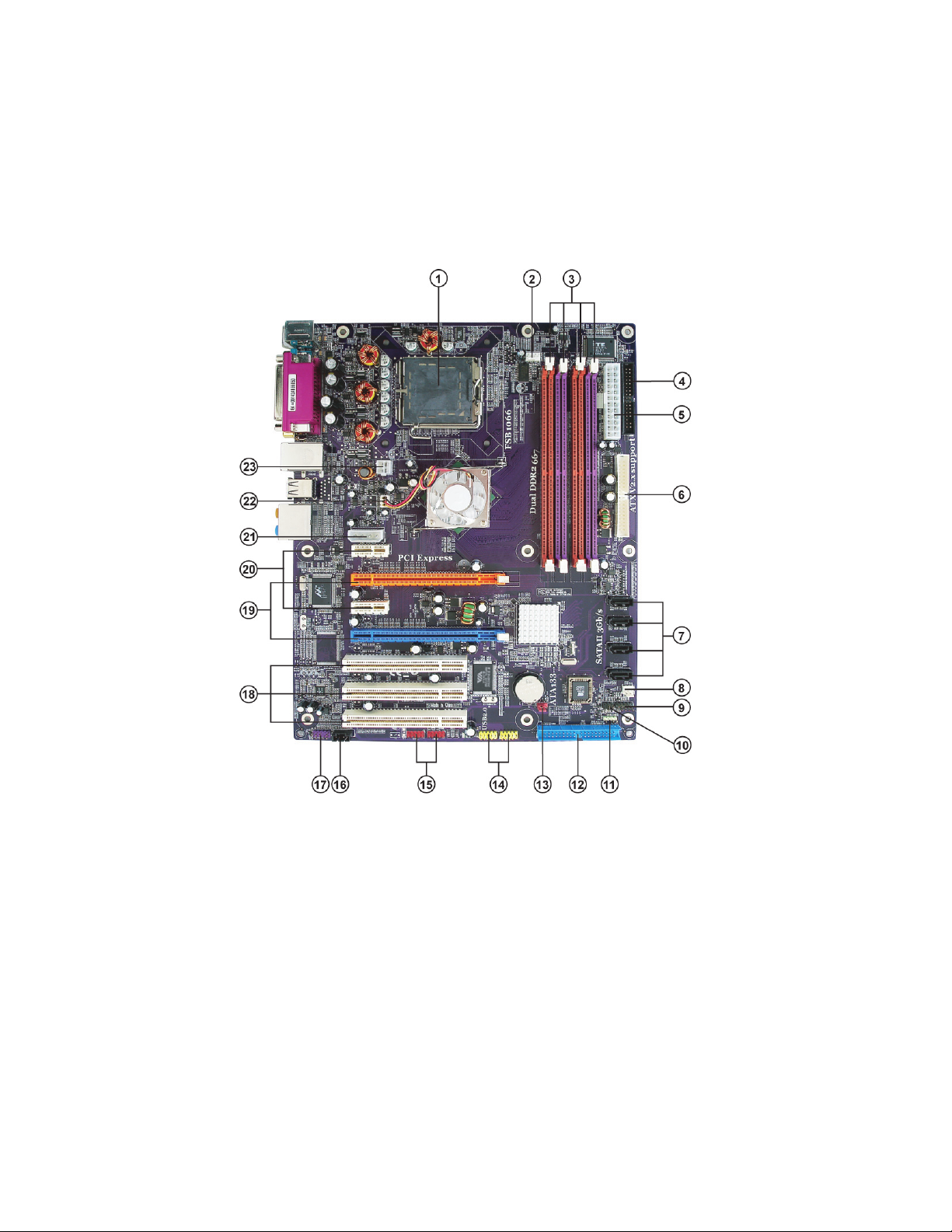
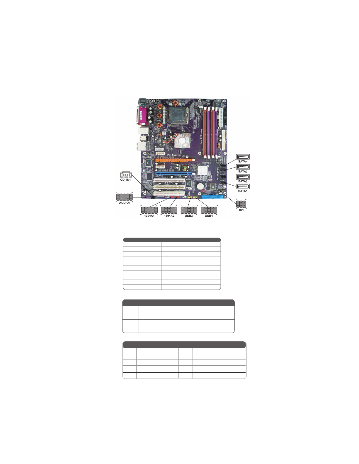
Motherboard Components
Introducing the Motherboard
Page 11

Table of Motherboard Components
LABEL COMPONENT
1 CPU Socket Pentium D/Pentium 4 Extreme Edition/Pentium
processor Extreme Edition CPUs
2 CPU_FAN CPU cooling fan connector
3 DIMM1~4 240-pin DDR2 SDRAM slots
4 FDD Floppy diskette drive connector
5 ATX1 Standard 24-pin ATX power connector
LGA775 socket for Pentium 4/Celeron D/
6 IDE2 Secondary IDE channel
7 SATA1~4 Serial ATA connectors
8 CAS_FAN1 Case fan connector
9 PANEL1 Panel connector switches/LED header
10 IR1 Internal infrared header
1 1 SPK1 Speaker header
12 IDE1 Primary IDE channel
13 CLR_CMOS Clear CMOS jumper
14 USB3~4 Front panel USB headers
15 1394A1~A2* Onboard 1394a headers
16 CD_IN1 Analog audio input connector
17 AUDIO1 Front panel audio header
18 PCI1~3 32-bit add-on card slots
19 PCIE2/4
20 PCIE1/3 PCI Express x1 slots
PCI Express x16 slots (SLI mode: x8+x8, single
PCI-E is x8 mode) for graphics interface
21 ATX4P1 Auxiliary power connector for graphic card
22 NB_FAN Northbridge fan connector
23 ATX12V1 Auxiliary 4-pin power connector
5
“*” stands for optional components and may not exist onboard.
This concludes Chapter 1. The next chapter explains how to install the motherboard.
Introducing the Motherboard
Page 12

6
Memo
Introducing the Motherboard
Page 13

Chapter 2
Installing the Motherboard
Safety Precautions
• Follow these safety precautions when installing the motherboard
• Wear a grounding strap attached to a grounded device to avoid damage from
static electricity
• Discharge static electricity by touching the metal case of a safely grounded
object before working on the motherboard
• Leave components in the static-proof bags they came in
• Hold all circuit boards by the edges. Do not bend circuit boards
Choosing a Computer Case
There are many types of computer cases on the market. The motherboard complies with
the specifications for the ATX system case. First, some features on the motherboard are
implemented by cabling connectors on the motherboard to indicators and switches on the
system case. Make sure that your case supports all the features required. Secondly, this
motherboard supports one or two floppy diskette drives and two enhanced IDE drives.
Make sure that your case has sufficient power and space for all drives that you intend to
install.
Most cases have a choice of I/O templates in the rear panel. Make sure that the I/O
template in the case matches the I/O ports installed on the rear edge of the motherboard.
This motherboard carries an ATX form factor of 305 x 244 mm. Choose a case that
accommodates this form factor.
Installing the Motherboard in a Case
7
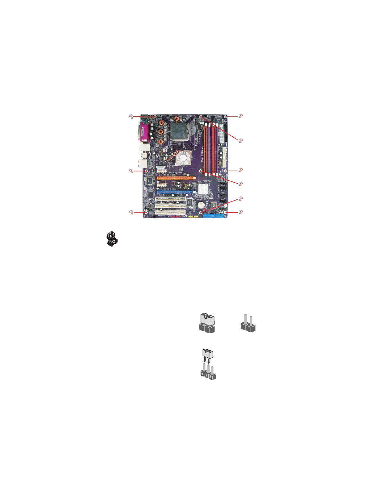
Refer to the following illustration and instructions for installing the motherboard in a case.
Most system cases have mounting brackets installed in the case, which correspond the holes
in the motherboard. Place the motherboard over the mounting brackets and secure the
motherboard onto the mounting brackets with screws.
Ensure that your case has an I/O template that supports the I/O ports and expansion slots
on your motherboard.
Installing the Motherboard
Page 14
8
Do not over-tighten the screws as this can stress the motherboard.
Checking Jumper Settings
This section explains how to set jumpers for correct configuration of the motherboard.
Setting Jumpers
Use the motherboard jumpers to set system configuration options. Jumpers with more than
one pin are numbered. When setting the jumpers, ensure that the jumper caps are placed on
the correct pins.
The illustrations show a 2-pin jumper. When
the jumper cap is placed on both pins, the
jumper is SHORT. If you remove the jumper
cap, or place the jumper cap on just one pin,
the jumper is OPEN.
This illustration shows a 3-pin jumper. Pins
1 and 2 are SHORT
SHORT OPEN
Installing the Motherboard
Page 15
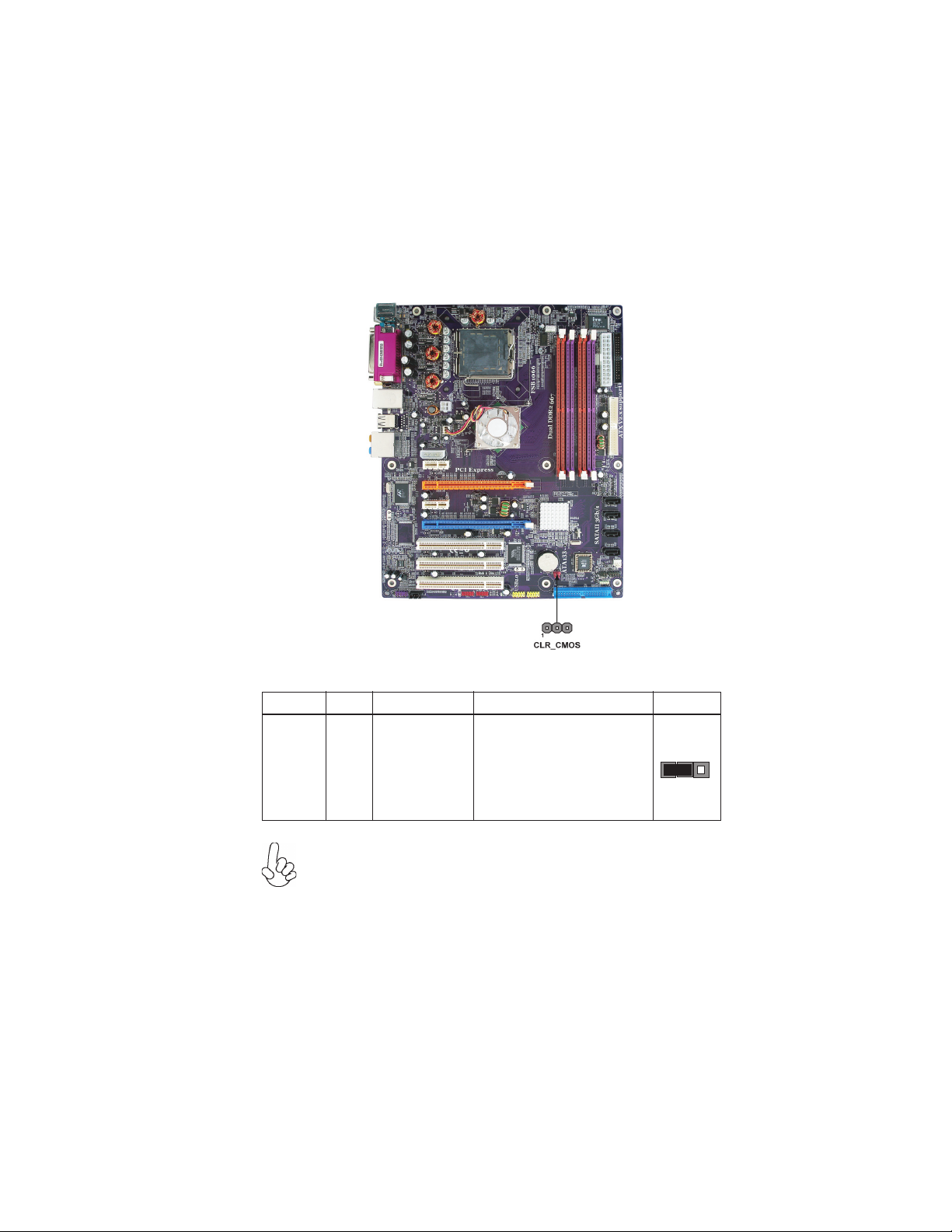
Checking Jumper Settings
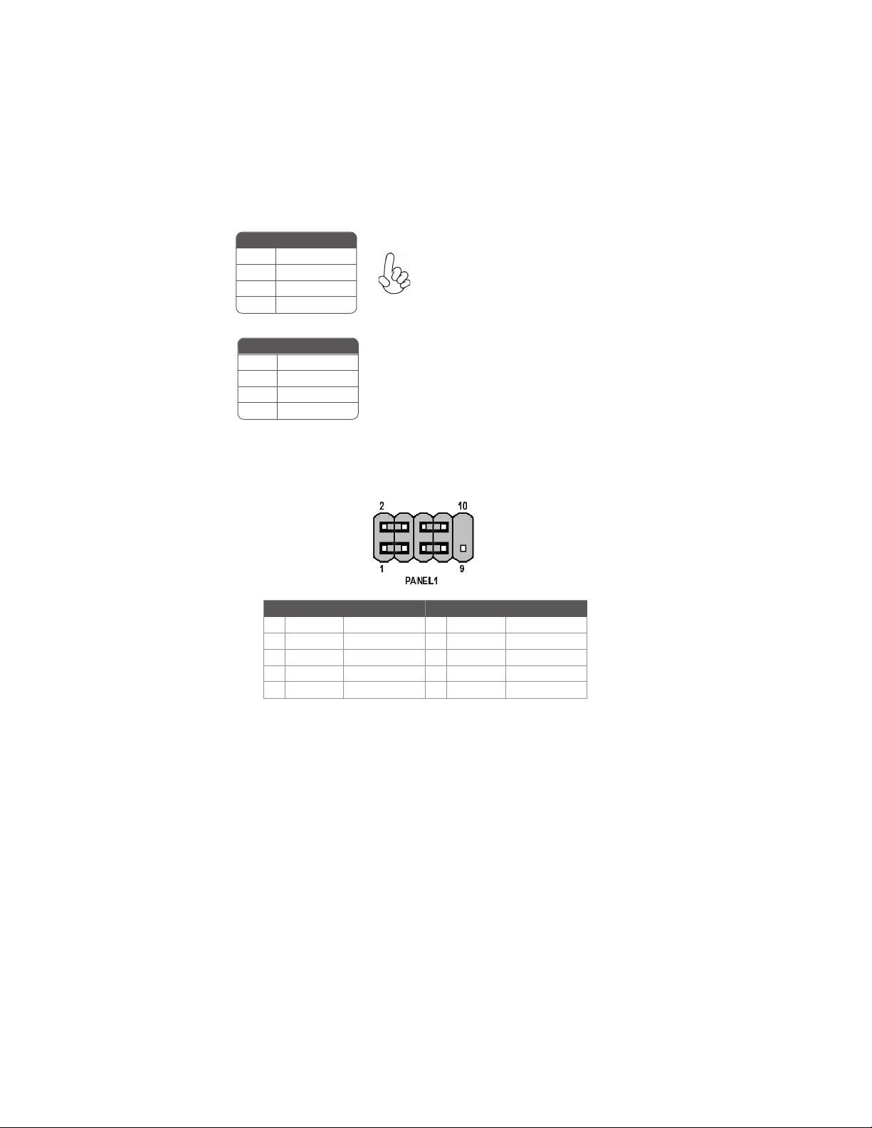
The following illustration shows the location of the motherboard jumpers. Pin 1 is labeled.
9
Jumper Settings
Jumper
CLR_CMOS
Type
3-pin CLEAR CMOS
To avoid the system instability after clearing CMOS, we recommend
users to enter the main BIOS setting page to “Load Optimized Defaults” and then “Save & Exit Setup”.
Description
Setting (default)
1-2: NORMAL
2-3: CLR_CMOS
Before clearing the
CMOS, make sure to
turn off the system.
Installing the Motherboard
CLR_CMOS
1
Page 16
10
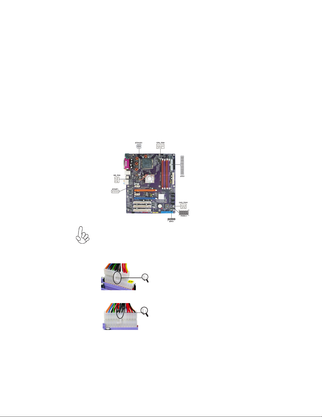
Connecting Case Components
After you have installed the motherboard into a case, you can begin connecting the motherboard components. Refer to the following:
1 Connect the CPU cooling fan cable to CPU_FAN.
2 Connect the case fan connector to CAS_FAN1.
3 Connect the northbridge fan connector to NB_FAN.
4 Connect the connector for graphics interface to ATX4P1.
5 Connect the case switches and indicator LEDs to the PANEL1.
6 Connect the standard power supply connector to ATX1.
7 Connect the auxiliary case power supply connector to ATX12V1.
8 Connect the case speaker cable to SPK1.
Connecting 20/24-pin power cable
Users please note that the 20-pin and 24-pin power cables can both be connected to the ATX1 connector. With the 20-pin power cable, just align the 20pin power cable with the pin 1 of the ATX1 connector. However, using 20-pin
power cable may cause the system to become unbootable or unstable because of
insufficient electricity. A minimum power of 300W is recommended for a fully
-configured system.
With ATX v1.x power supply, users please
note that when installing 20-pin power cable,
the latche of power cable falls on the left
side of the ATX1 connector latch, just as the
picture shows.
20-pin power cable
With ATX v2.x power supply, users please
note that when installing 24-pin power cable,
the latches of power cable and the ATX1
match perfectly.
24-pin power cable
Installing the Motherboard
Page 17
CPU_FAN: CPU Cooling FAN Power Connector
Pin Signal Name Function
1 GND System Ground
2 +12V Power +12V
3 Sense Sensor
4 PWM CPU FAN control
Users please note that the fan connector supports the CPU cooling
fan of 1.1A~2.2A (26.4W max.) at +12V.
CAS_FAN1 :CASE FAN Power Connector
Pin Signal Name Function
1 GND System Ground
2 +12V Power +12V
3 Sense Sensor
NB_FAN : Northbridge FAN Power Connector
Pin Signal Name Function
Pin Signal Name Function
1 GND System Ground
2 +12V Power +12V
3 Sense Sensor
ATX12V1: ATX 12V Power Connector
11
Pin Signal Name
1 Ground
2 Ground
3 +12V
4 +12V
ATX1: ATX 24-pin Power Connector
Pin Signal Name Pin Signal Name
1 +3.3V 13 +3.3V
2 +3.3V 14 -12V
3 GROUND 15 GROUND
4 +5V 16 PS_ON
5 GROUND 17 GROUND
6 +5V 18 GROUND
7 GROUND 19 GROUND
8 PWR OK 20 -5V
9 +5VSB 21 +5V
10 +12V 22 +5V
11 +12V 23 +5V
12 +3.3V 24 GROUND
Installing the Motherboard
Page 18
12
ATX4P1: Auxiliary Power Connector for Graphics Interface
Pin Signal Name
1 NC
2 GND
3 GND
Make sure to connect a 4-pin ATX power cable
to ATX4P1; otherwise, the system will be unstable.
4 +12V
SPK1: Internal speaker
Pin Signal Name
1 VCC
2 Key
3 NC
4 Signal
Front Panel Connector
The front panel connector (PANEL1) provides a standard set of switch and LED connectors commonly found on ATX or micro-ATX cases. Refer to the table below for information:
Pin Signal Function Pin Signal Function
1 HD_LED_P Hard disk LED(+) 2 FP PWR/SLP *MSG LED(+)
3 HD_LED_N Hard disk LED(-)
5 RST_SW_N Reset Switch(-)
7 RST_SW_P Reset Switch(+)
9 RSVD Reserved
* MSG LED (dual color or single color)
4 FP PWR/SLP *MSG LED(-)
6 PWR_SW_P Power Switch (+)
8 PWR_SW_N Power Switch (-)
10 Key No pin
Hard Drive Activity LED
Connecting pins 1 and 3 to a front panel mounted LED provides visual indication that data
is being read from or written to the hard drive. For the LED to function properly, an IDE
drive should be connected to the onboard IDE interface. The LED will also show activity
for devices connected to the SCSI (hard drive activity LED) connector.
Power/Sleep/Message waiting LED
Connecting pins 2 and 4 to a single or dual-color, front panel mounted LED provides power
on/off, sleep, and message waiting indication.
Reset Switch
Supporting the reset function requires connecting pin 5 and 7 to a momentary-contact
switch that is normally open. When the switch is closed, the board resets and runs POST.
Installing the Motherboard
Page 19

Power Switch
Supporting the power on/off function requires connecting pins 6 and 8 to a momentarycontact switch that is normally open. The switch should maintain contact for at least 50 ms
to signal the power supply to switch on or off. The time requirement is due to internal debounce circuitry. After receiving a power on/off signal, at least two seconds elapses before
the power supply recognizes another on/off signal.
Installing Hardware
Installing the Processor
Caution: When installing a CPU heatsink and cooling fan make sure that
you DO NOT scratch the motherboard or any of the surface-mount
resistors with the clip of the cooling fan. If the clip of the cooling fan
scrapes across the motherboard, you may cause serious damage to the
motherboard or its components.
On most motherboards, there are small surface-mount resistors near the
processor socket, which may be damaged if the cooling fan is carelessly
installed.
Avoid using cooling fans with sharp edges on the fan casing and the clips.
Also, install the cooling fan in a well-lit work area so that you can clearly
see the motherboard and processor socket.
Before installing the Processor
This motherboard automatically determines the CPU clock frequency and system bus
frequency for the processor. You may be able to change these settings by making changes to
jumpers on the motherboard, or changing the settings in the system Setup Utility. We
strongly recommend that you do not over-clock processors or other components to run
faster than their rated speed.
13
Warning: Over-clocking components can adversely affect the reliability
of the system and introduce errors into your system. Over-clocking can
permanently damage the motherboard by generating excess heat in
components that are run beyond the rated limits.
This motherboard has an LGA 775 socket. When choosing a processor, consider the
performance requirements of the system. Performance is based on the processor design, the
clock speed and system bus frequency of the processor, and the quantity of internal cache
memory and external cache memory.
Installing the Motherboard
Page 20
14
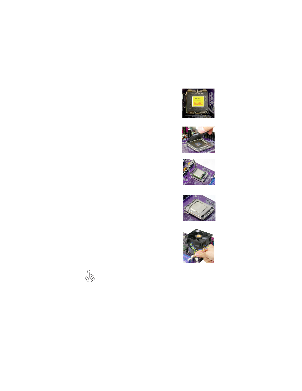
CPU Installation Procedure
The following illustration shows CPU installation components.
A. Read and follow the instructions shown on the
sticker on the CPU cap.
B. Unload the cap
· Use thumb & forefinger to hold the
lifting tab of the cap.
· Lift the cap up and remove the cap
completely from the socket.
C. Open the load plate
· Use thumb & forefinger to hold the
hook of the lever, pushing down and pulling
aside unlock it.
· Lift up the lever.
· Use thumb to open the load plate. Be
careful not to touch the contacts.
D. Install the CPU on the socket
· Orientate CPU package to the socket.
Make sure you match triangle marker
to pin 1 location.
E. Close the load plate
· Slightly push down the load plate onto the
tongue side, and hook the lever.
· CPU is locked completely.
F. Apply thermal grease on top of the CPU.
G. Fasten the cooling fan supporting base onto
the CPU socket on the motherboard.
H. Make sure the CPU fan is plugged to the
CPU fan connector. Please refer to the CPU
cooling fan user’s manual for more detail
installation procedure.
1.To achieve better airflow rates and heat dissipation, we suggest that you
use a high quality fan with 3800 rpm at least. CPU fan and heatsink
installation procedures may vary with the type of CPU fan/heatsink sup plied. The form and size of fan/heatsink may also vary.
2.Do not remove the CPU cap from the socket before installing a CPU.
3.Return Material Authorization (RMA) requests will be accepted only if the
motherboard comes with the cap on the LGA775 socket.
Installing the Motherboard
Page 21
Installing Memory Modules
This motherboard accommodates four memory modules. It can support four 240-pin DDR2
667/533 DDR2 SDRAM. The total memory capacity is 16 GB.
DDR2 SDRAM memory module table
Memory module Memory Bus
DDR2 533 266MHz
DDR2 667 333MHz
You must install at least one module in any of the four slots. Each module can be installed
with 4 GB of memory; total memory capacity is 16 GB.
Do not remove any memory module from its antistatic packaging until you
are ready to install it on the motherboard. Handle the modules only by
their edges. Do not touch the components or metal parts. Always wear a
grounding strap when you handle the modules.
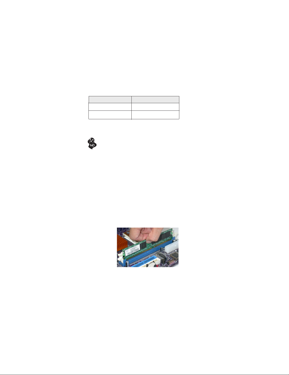
Installation Procedure
Refer to the following to install the memory modules.
1 This motherboard supports unbuffered DDR2 SDRAM .
2 Push the latches on each side of the DIMM slot down.
3 Align the memory module with the slot. The DIMM slots are keyed with
notches and the DIMMs are keyed with cutouts so that they can only be
installed correctly.
4 Check that the cutouts on the DIMM module edge connector match the notches
in the DIMM slot.
5 Install the DIMM module into the slot and press it firmly down until it seats
correctly. The slot latches are levered upwards and latch on to the edges of
the DIMM.
6 Install any remaining DIMM modules.
15
Installing the Motherboard
Page 22
16
Table A: DDR2 QVL (Qualified Vender List)
The following DDR2 memory modules have been tested and qualified
for use with this motherboard.
Type Size Vendor Module Name
A-DATA M2OHY2F3G3110A1B0Z
Kingston KVR533D2N4
256MB
DDR2 533
512MB
DDR2 667 512MB
Infineon HYS64T32000HU-3.7-A
Ramaxel RML 1040M28D5F-533
SAMSUNG M378T3253FGO-CD5
AENEON AET660UD00-370A98X
SAMSUNG M378T6553BGO-CD5
CORSAIR VS512MB667D2
KINGMAX KLCC28F-
NANYA NT512T64U88A0BY-3C
SyncMAX S2R512M-08RCA-5300
TwinMOS 8G-25JK5-EBT
Installing the Motherboard
Page 23
Installing a Hard Dish Drive/CD-ROM/SATA Hard Drive
This section describes how to install IDE devices such as a hard disk drive and a CD-ROM
.
drive
About IDE Devices
Your motherboard has two IDE channel interfaces(IDE1 & IDE2). Two IDE ribbon cables
supporting four IDE devices is bundled with the motherboard.
You must orient the cable connector so that the pin1 (color) edge of the
cable corresponds to the pin 1 of the I/O port connector.
IDE1: Primary IDE Connector
The first hard drive should always be connected to IDE1.
IDE2: Secondary IDE Connector
The secondary drive on this controller must be set to slave mode. The configuration is the
same as IDE1.
17
IDE devices enclose jumpers or switches used to set the IDE device as MASTER or SLAVE.
Refer to the IDE device user’s manual. Installing two IDE devices on one cable, ensure that
one device is set to MASTER and the other device is set to SLAVE. The documentation of
your IDE device explains how to do this.
About SATA Connectors
Your motherboard features four SATA connectors supporting a total of four drives. SATA ,
or Serial ATA (Advanced Technology Attachment) is the standard interface for the IDE
hard drives which are currently used in most PCs. These connectors are well designed and
will only fit in one orientation. Locate the SATA connectors on the motherboard and follow
the illustration below to install the SATA hard drives.
Installing Serial ATA Hard Drives
To install the Serial ATA (SATA) hard drives, use the SATA cable that supports the Serial
ATA protocol. This SATA cable comes with an SATA power cable. You can connect either
end of the SATA cable to the SATA hard drive or the connector on the motherboard.
SATA cable (optional)
SATA power cable (optional)
Installing the Motherboard
Page 24
18
Refer to the illustration below for proper installation:
1 Attach either cable end to the connector on the motherboard.
2 Attach the other cable end to the SATA hard drive.
3 Attach the SATA power cable to the SATA hard drive and connect the other
end to the power supply.
This motherboard does not support the “Hot-Plug” function.
Installing a Floppy Diskette Drive
The motherboard has a floppy diskette drive (FDD) interface and ships with a diskette drive
ribbon cable that supports one or two floppy diskette drives. You can install a 5.25-inch
drive and a 3.5-inch drive with various capacities. The floppy diskette drive cable has one
type of connector for a 5.25-inch drive and another type of connector for a 3.5-inch drive.
You must orient the cable connector so that the pin 1 (color) edge of the
cable corresponds to the pin 1 of the I/O port connector.
FDD: Floppy Disk Connector
This connector supports the provided floppy drive ribbon cable. After connecting the single
end to the onboard floppy connector, connect the remaining plugs on the other end to the
floppy drives correspondingly.
Installing the Motherboard
Page 25
Installing Add-on Cards
The slots on this motherboard are designed to hold expansion cards and connect them to the
system bus. Expansion slots are a means of adding or enhancing the motherboard’s features
and capabilities. With these efficient facilities, you can increase the motherboard’s capabilities by adding hardware that performs tasks that are not part of the basic system.
19
PCIE1/3
Slots
PCIE2/4
Slots
PCI 1~3
Slots
The PCI Express x1 slots are fully compliant to the PCI Express Base
Specification revision 1.0a.
The PCI Express x16 slot is used to install an external PCI Express graphics
card that is fully compliant to the PCI Express Base Specification revision
1.0a. (SLI Mode: x8+x8, single PCI-E is x8 mode)
This motherboard is equipped with three standard PCI slots. PCI stands for
Peripheral Component Interconnect and is a bus standard for expansion
cards, which for the most part, is a supplement of the older ISA bus standard.
The PCI slots on this board are PCI v2.3 compliant.
1. Before installing an add-on card, check the documentation for the card
carefully. If the card is not Plug and Play, you may have to manually
configure the card before installation.
2. PCIE3 slot will be disabled when PCIE4 slot is installed.
Installing the Motherboard
Page 26

20
Follow these instructions to install add-on cards:
1. Open the chassis and then remove the slot bracket from the case where you will
be installing the expansion cards.
2. Install your graphics card in the proper slot by pressing the card firmly into the
slot.
3. Drive in the screw to secure the slot bracket of the expanson card.
4. Replace your computer’s chassis cover.
5. Power on the computer, if necessary, set up BIOS utility of expansion card from
BIOS.
6. Install related driver to complete the installation.
Installing two graphics cards
Notes: 1. The two PCIE x16 slots (SLI Mode: x8+x8, single PCI-E is x8 mode) run in two modes. With
only one PCI Express Graphics card, install it onto PCIE2 slot by default. Having two PCI
Express Graphics cards at hand, set them up onto PCIE2 and PCIE4 slots simultaneously.
2. The Scalable D.G.E. supports a four-monitor configuration when
4 slot are working simultaneously.
3. Please note that the graphics card driver supports Windows 2000/XP only.
4. Make sure to connect a 4-pin ATX power cable to the ATX4P1; otherwise, the system will
be unstable.
PCIE2 slot and PCIE
Installing the Motherboard
Page 27
Connecting Optional Devices
Refer to the following for information on connecting the motherboard’s optional devices:
AUDIO1: Front Panel Audio header
This header allows the user to install auxiliary front-oriented microphone and line-out ports
for easier access.
Pin Signal Name Function
Pin Signal Name FunctionPin Signal Name Function
1 MIC2_RL Smart jack F left channel
2 AGND AGND
3 MIC2_RR Smart jack F right channel
4 VCC3 Front Audio detect
5 LINE2_RR Smart jack E right channel
6 RET_R NC
7 REVD SENSE B
8 Key No pin
9 LINE2_RL Smart jack E left channel
10 RET_L NC
CD_IN1: Analog audio input connector
Pin Signal Name Function
1 CD in_R CD In right channel
2 GND Ground
3 GND Ground
4 CD in_L CD In left channel
1394A1~A2(Optional): 1394A headers
Pin Signal Name
Pin Signal Name Function
A1P
1
3 GND 4 GND
5 B1P 6 B1M
7 CPWR 8 CPWR
9 Key 10 GN D
Pin Signal Name
A1M
2
Installing the Motherboard
21
Page 28
22
USB3/4: Front Panel USB headers
The motherboard has four USB ports installed on the rear edge I/O port array. Additionally,
there are two USB headers onboard. Use the auxiliary USB headers to connect the frontmounted ports to the motherboard.
Pin Signal Name Function
1 USBPWR Front Panel USB Power
2 USBPWR Front Panel USB Power
3 USB_FP_P0- USB Port 0 Negative Signal
4 USB_FP_P1- USB Port 1 Negative Signal
5 USB_FP_P0+ USB Port 0 Positive Signal
6 USB_FP_P1+ USB Port 1 Positive Signal
7 GND Ground
8 GND Ground
9 Key No pin
10 USB_FP_OC0 Overcurrent signal
IR1: Infrared header
The mainboard supports an Infrared (IR1) data port. Infrared ports allows the wireless
exchange of information between your computer and similarly equipped devices such as
printers, laptops, Personal Digital Assistants (PDAs), and other computers.
Pin Signal Name Function
1 Not Assigned Not assigned
2 Key No pin
3 +5V IR Power
4 GND Ground
5 IR_TX IrDA serial output
6 IR_RX IrDA serial input
SATA1/2/3/4: Serial ATA connectors
These connectors are used to support the new Serial ATA devices for the highest date
transfer rates (3.0 Gb/s), simpler disk drive cabling and easier PC assembly. It eliminates
limitations of the current Parallel ATA interface. But maintains register compatibility and
software compatibility with Parallel ATA.
Pin Signal Name
Pin Signal Name Function
1 Ground 2 TX+
3 TX- 4 Ground
5 RX- 6 RX+
7 Ground - -
Pin Signal Name
Installing the Motherboard
Page 29

Connecting I/O Devices
The backplane of the motherboard has the following I/O ports:
PS2 Mouse Use the upper PS/2 port to connect a PS/2 pointing device.
PS2 Keyboard Use the lower PS/2 port to connect a PS/2 keyboard.
23
Parallel Port (LPT2) Use LPT2 to connect printers or other parallel communications
Serial Port Use the COM port to connect serial devices such as mice or
(COM1) fax/modems. COM1 is identified by the system as COM1/3.
Optical S/PDIF Connects to external digital audio output devices.
output port
Coaxial S/PDIF Connects to external digital audio output devices.
output port
LAN Port (optional) Connect an RJ-45 jack to the LAN port to connect your computer
USB Ports Use the USB ports to connect USB devices.
Audio Ports
A: Center & Woofer D: Line-in
devices.
to the Network.
Use the audio jacks to connect audio devices. The D port is for
stereo line-in signal, while the F port is for microphone in signal.
This mainboard supports 8-channel audio devices that correspond
to the A, B, C and E port respectively. In addition, all of the 3
ports, B, C and E provide users with both right & left channels
individually. Users please refer to the following note for specific
port function definition.
B: Back Surround E: Front Out
C: Side Surround F: Mic_in Rear
The above port definition can be changed to audio input or
audio output by changing the driver utility setting.
This concludes Chapter 2. The next chapter covers the BIOS.
Installing the Motherboard
Page 30

24
Memo
Installing the Motherboard
Page 31

Chapter 3
Using BIOS
About the Setup Utility
The computer uses the latest Award BIOS with support for Windows Plug and Play. The
CMOS chip on the motherboard contains the ROM setup instructions for configuring the
motherboard BIOS.
The BIOS (Basic Input and Output System) Setup Utility displays the system’s configuration status and provides you with options to set system parameters. The parameters are
stored in battery-backed-up CMOS RAM that saves this information when the power is
turned off. When the system is turned back on, the system is configured with the values you
stored in CMOS.
The BIOS Setup Utility enables you to configure:
• Hard drives, diskette drives and peripherals
• Video display type and display options
• Password protection from unauthorized use
• Power Management features
The settings made in the Setup Utility affect how the computer performs. Before using the
Setup Utility, ensure that you understand the Setup Utility options.
25
This chapter provides explanations for Setup Utility options.
The Standard Configuration
A standard configuration has already been set in the Setup Utility. However, we recommend
that you read this chapter in case you need to make any changes in the future.
This Setup Utility should be used:
• when changing the system configuration
• when a configuration error is detected and you are prompted to make changes
to the Setup Utility
• when trying to resolve IRQ conflicts
• when making changes to the Power Management configuration
• when changing the password or making other changes to the Security Setup
Entering the Setup Utility
When you power on the system, BIOS enters the Power-On Self Test (POST) routines.
POST is a series of built-in diagnostics performed by the BIOS. After the POST routines are
completed, the following message appears:
Using BIOS
Page 32

26
Press DEL to enter SETUP
Press the delete key to accesse the BIOS Setup Utility.
Phoenix-AwardBIOS CMOS Setup Utility
Standard CMOS Features Load Fail-Safe Defaults
Advanced BIOS Features
Advanced Chipset Features Se t Supervisor Password
Integrated Peripherals Set User Password
Power Management Setup Save & Exit Setup
PnP/PCI Configurations Exit Without Saving
PC Health Status
Load Optimized Defaults
ESC: Quit
F10: Save & Exit Setup
Load Optimized Defaults
BIOS Navigation Keys
The BIOS navigation keys are listed below:
KEY FUNCTION
Enter
+/-/PU/PD
ESC
F2
F6
F7
F10
Move
Select
Value
Exit
General HelpF1
Item Help
Previous ValuesF5
Fail-Safe Defaults
Optimized Defaults
Save
: Select Item
Using BIOS
Page 33

Updating the BIOS
You can download and install updated BIOS for this motherboard from the manufacturer’s
Web site. New BIOS provides support for new peripherals, improvements in performance,
or fixes for known bugs. Install new BIOS as follows:
1 If your motherboard has a BIOS protection jumper, change the setting to allow
BIOS flashing.
2 If your motherboard has an item called Firmware Write Protect in Advanced
BIOS features, disable it. (Firmware Write Protect prevents BIOS from being
overwritten.
3 Create a bootable system disk. (Refer to Windows online help for information
on creating a bootable system disk.)
4 Download the Flash Utility and new BIOS file from the manufacturer’s Web
site. Copy these files to the system diskette you created in Step 3.
5 Turn off your computer and insert the system diskette in your computer’s
diskette drive. (You might need to run the Setup Utility and change the boot
priority items on the Advanced Setup page, to force your computer to boot
from the floppy diskette drive first.)
6 At the A:\ prompt, type the Flash Utility program name and press <Enter>.
7 Type the filename of the new BIOS in the “File Name to Program”text box.
Follow the onscreen directions to update the motherboard BIOS.
8 When the installation is complete, remove the floppy diskette from the diskette
drive and restart your computer. If your motherboard has a Flash BIOS jumper,
reset the jumper to protect the newly installed BIOS from being overwritten.
The computer will restart automatically.
27
Using BIOS
When you start the Setup Utility, the main menu appears. The main menu of the Setup
Utility displays a list of the options that are available. A highlight indicates which option is
currently selected. Use the cursor arrow keys to move the highlight to other options. When
an option is highlighted, execute the option by pressing <Enter>.
Some options lead to pop-up dialog boxes that prompt you to verify that you wish to
execute that option. Other options lead to dialog boxes that prompt you for information.
Some options (marked with a triangle
values for the option. Use the cursor arrow keys to scroll through the items in the submenu.
In this manual, default values are enclosed in parenthesis. Submenu items are denoted by a
triangle
.
) lead to submenus that enable you to change the
Using BIOS
Page 34

28
Standard CMOS Features
This option displays basic information about your system.
Phoenix - AwardBIOS CMOS Setup Utility
Standard CMOS Features
Date (mm:dd:yy)
Time (hh:mm:ss)
IDE Channel 0 Master
IDE Channel 0 Slave
IDE Channel 1 Master
IDE Channel 1 Slave
IDE Channel 2 Master
IDE Channel 3 Master
IDE Channel 4 Master
IDE Channel 5 Master
Drive A
Drive B
Floppy 3 Mode Support [Disabled]
Halt On
Base Memory
Extended Memory
Total Memory
: Move Enter: Select +/-/PU/PD:Value F10:Save ESC:Exit F1: General Help
F5: Previous Values F6: Fail-Safe Defaults F7: Optimized Defaults
Date and Time
The Date and Time items show the current date and time on the computer. If
you are running a Windows OS, these items are automatically updated whenever you make
changes to the Windows Date and Time Properties utility.
IDE Devices
Your computer has two IDE channels and each channel can be installed with one or two
devices (Master and Slave). In addition, this motherboard supports two SATA channels and
each channel allows one SATA device to be installed. Use these items to configure each
device on the IDE channel.
Press <Enter> to display the submenu:
IDE HDD Auto-Detection
IDE Channel 0 Slave
Access Mode
Capacity
Cylinder
Head
Precomp
Landing Zone
Sector
Wed, Jan 1 2003
5 : 29 : 17
[ None]
[ None]
[ None]
[ None]
[ None]
[ None]
[ None]
[ None]
[1.44, 3.5 in.]
[ None]
[All Errors]
640K
523264 K
524288 K
Phoenix-AwardBIOS CMOS Setup Utility
IDE Channel 0 Master
[ Press Enter]
[ Auto]
[ Auto]
0 MB
0
0
0
0
0
Item Help
Menu Level
Change the day, month, year
and century
Menu Level
To Auto-Detect the HDD’
size, head... on this channel
Item Help
: Move Enter: Select +/-/PU/PD:Value F10:Save ESC:Exit F1: General Help
F5: Previous Values F6: Fail-Safe Defaults F7: Optimized Defaults
Using BIOS
Page 35

IDE HDD Auto-Detection
Press <Enter> while this item is highlighted to prompt the Setup Utility to automatically
detect and configure an IDE device on the IDE channel.
If you are setting up a new hard disk drive that supports LBA mode, more
than one line will appear in the parameter box. Choose the line that lists LBA
for an LBA drive.
IDE Channel 0/1 Master/Slave IDE/Extended IDE Drives (Auto)
Leave this item at Auto to enable the system to automatically detect and configure IDE
device on the channel. If it fails to find a device, change the value to Manual and then
manually configure the drive by entering the characteristics of the drive in the items
described below. Please noted that if you choose IDE Channel 2/3 Master, the item may
change to Extended IDE Drive.
Refer to your drive’s documentation or look on the drive casing if you need to obtain this
information. If no device is installed, change the value to None.
Before attempting to configure a hard disk drive, ensure that you have the
configuration information supplied by the manufacturer of your hard drive.
Incorrect settings can result in your system not recognizing the installed hard
disk.
Access Mode (Auto)
This item defines ways that can be used to access IDE hard disk such as LBA (Large Block
Addressing). Leave this value at Auto and the system will automatically decide the fastest
way to access the hard disk drive. If you choose IDE Channel 2/3 Master, the item only have
Large and Auto.
Press <Esc> to return to the Standard CMOS Feature page.
29
Drive A/B (1.44M, 3.5 in./None)
These items define the characteristics of any diskette drive attached to the system.
You can connect one or two diskette drives.
Floppy 3 Mode Support (Disabled)
Floppy 3 mode refers to a 3.5-inch diskette with a capacity of 1.2 MB. Floppy 3 mode is
sometimes used in Japan.
Halt On (All Errors)
This item determines whether the system stops if an error is detected during system bootup. At defaults “All Errors”, the system-boot will stop for all errors.
Base Memory, Extended Memory, and Total Memory
These items are automatically detected by the system at start up time. These are displayonly fields. You cannot make changes to these fields.
Press <Esc> to return to the main menu setting page.
Using BIOS
Page 36

30
3
Advanced BIOS Features
This option defines advanced information about your system.
CPU Features
Hard Disk Boot Priority [Press Enter]
CPU L1 & L2 Cache [Enabled]
Hyper-Threading Technology [Enabled]
Quick Power On Self Test [Enabled]
First Boot Device [Floppy]
Second Boot Device [Hard Disk]
Third Boot Device [CDROM]
Boot Other Device [Enabled]
Swap Floppy Device [Disabled]
Boot Up Floppy Seek [Disabled]
Boot Up NumLock Status [On]
Gate A20 Option [Fast]
Typematic Rate Setting [Disabled]
x
Typematic Rate (Chars/Sec) 6
x
Typematic Delay (Msec) 250
Security Option [Setup]
OS Select For DRAM > 64 MB [Non-OS2]
Small Logo(EPA) Show [Disabled]
F5: Previous Values F6: Fail-Safe Defaults F7: Optimized Defaults
CPU Features (Press Enter)
Scroll to this item and press <Enter> to view the following screen: .
Thermal Management
Limit CPUID MaxVal [Disabled]
C1E Function [Auto]
Execute Disable Bit [Enabled]
Phoenix -AwardBIOS CMOS Setup Utility
Advanced BIOS Features
[Press Enter]
: Move Enter: Select +/-/PU/PD:Value F10:Save ESC:Exit F1: General Help
Phoenix -AwardBIOS CMOS Setup Utility
CPU Features
[Thermal Monitor 1]
Item Help
Menu Level
2
Item Help
Menu Level
Thermal Monitor 1 (On die
throtting)
Thermal Monitor 2 (Ratio &
VID transition)
: Move Enter: Select +/-/PU/PD:Value F10:Save ESC:Exit F1: General Help
F5: Previous Values F6: Fail-Safe Defaults F7: Optimized Defaults
Thermal Management (Thermal Monitor 1)
This item displays CPU’s temperature and enables you to set a safe temperature to Prescott
CPU.
Limit CPUID MaxVal (Disabled)
This item can support Prescott CPUs for old OS. Users please note that under NT 4.0, it
must be set “Enabled”, while under WinXP, it must be set “Disabled”.
C1E Support (Enabled)
Enabling this item to reduce power consumption in idle systems.
Using BIOS
Page 37

Execute Disable Bit (Enabled)
This item allows the processor to classify areas in memory by where application code
can execute and where it cannot. when a malicious worm attempts to insert code in the
buffer, the processor disables code execution, preventing damage or worm propagation.
Replacing older computers with Execute Disable Bit-enabled systems can halt worm
attacks, reducing the need for virus related repair.
Press <Esc> to return to the Advanced BIOS Feature page.
Hard Disk Boot Priority (Press Enter)
Scroll to this item and press <Enter> to view the following screen: Use this table to decide
the disk boot priority.
Phoenix -AwardBIOS CMOS Setup Utility
Hard Disk Boot Priority
31
1. Bootable Add-in Cards
: Move Enter: Select +/-/PU/PD:Value F10:Save ESC:Exit F1: General Help
F5: Previous Values F6: Fail-Safe Defaults F7: Optimized Defaults
Item Help
Menu Level
Use < > or < > to select a
device, then press <+> to
move it up, or <-> to move it
down the list. Press <ESC>
to exit this menu.
Bootable Add-in Card
This screen enables users to set the sequence of the bootable devices in system.
Press <Esc> to return to the Advanced BIOS Feature page.
CPU L1 & L2 Cache (Enabled)
All processors that can be installed motherboard use CPU internal cache memory to improve performance. This items enables or disables the actual CPU interal level 1/2 cache
function.Leave this item at default value for better performance.
Hyper-Threading Technology (Enabled)
This item is only available when the chipset supports Hyper-Threading and you are using a
Hyper-Threading CPU.
Quick Power On Self Test (Enabled)
Enable this item to shorten the power on self testing (POST) and have your system start up
faster. You might like to enable this item after you confident that your system hardware is
operating smoothly.
First/Second/Third Boot Device (Floppy/Hard Disk/CDROM)
Use these three items to select the priority and order of the devices that your system
searches for an operating system at start-up time.
Using BIOS
Page 38

32
Boot Other Device (Enabled)
When enabled, the system searches all other possible locations for operating system if it
fails to find one in the devices specified under the First, Second, and Third boot devices.
Swap Floppy Drive (Disabled)
If you have two floppy diskette drives in your system, this item allows you to swap the
assigned drive letters so that drive A becomes drive B, and drive B becomes drive A.
Boot Up Floppy Seek (Disabled)
If this item is enabled, it checks the size of the floppy disk drives at start-up time. You don’t
need to enable this item unless you have a legacy diskette drive with 360K capacity.
Boot Up NumLock Status (On)
This item defines if the heyboard Num Lock key is active when your system is started.
Gate A20 Option (Fast)
This item defines how the system handles legacy software that was written for an earlier
generation of processors. Leave this item at the default value.
Typematic Rate Setting (Disabled)
If this item is enabled, you can use the following two items to set the typematic rate and
typematic delay settings for your keyboard.
♦ Typematic Rate (Chars/Sec): Use this item to define how many characters per second
are generated by a held-down key.
♦ Typematic Delay (Msec): Use this item to define how many milliseconds must elapse
before a held-down key begins generating repeat charachers.
Security Option (Setup)
If you have installed password protection, this item defines if the password is required at
system start up, or if it is only required when a user tries to enter the Setup Utility.
OS Select For DRAM > 64MB (Non-OS2)
This item is only required if you have installed more than 64 MB of memory and you are
running the OS/2 operating system. Otherwise, leave this item at the default.
Small Logo (EPA) Show (Disabled)
Enables or disables the display of the EPA logo during boot-up.
Press <Esc> to return to the main menu setting page.
Using BIOS
Page 39

Advanced Chipset Features
These items define critical timing parameters of the motherboard. You should leave the
items on this page at their default values unless you are very familiar with the technical
specifications of your system hardware. If you change the values incorrectly, you may
introduce fatal errors or recurring instability into your system.
Phoenix-AwardBIOS CMOS Setup Utility
Advanced Chipset Features
Performance Options
Spread Spectrum Control [Press Enter]
LDT Frequency [4x]
Syatem BIOS Cacheable [Disabled]
Video RAM Cacheable [Disabled]
: Move Enter: Select +/-/PU/PD:Value F10:Save ESC:Exit F1: General Help
F5: Previous Values F6: Fail-Safe Defaults F7: Optimized Defaults
Performance Options (Press Enter)
Scroll to this item and press <Enter> to view the following screen:
Phoenix-AwardBIOS CMOS Setup Utility
Performance Options
PCIE Frequency (MHz)
CPU Clock Ratio [19 x]
CPU Core Unlock [Disabled]
FSB Turbo Mode [Disabled]
MEM Turbo Mode [Disabled]
System Clock Mode [Optimal]
x
New FSB Speed (QDR) Auto
Current FSB Speed (QDR) 800.0 MHz
Target FSB Speed (QDR) 800.0 MHz
x
New MEM Speed (QDR) Auto
Current MEM Speed (DDR) 666.7 MHz
Target MEM Speed (DDR) 666.7 MHz
Memory Timings [Optimal]
Current CAS-RCD-RP-RAS-RC 5-5-5-15-28 (1T)
x
Target CAS-RCD-RP-RAS-RC 5-5-5-15-28 (1T)
x
T(CAS) Auto
x
T(RCD) Auto
x
T(RP) Auto
x
T(RAS) Auto
x
T(RC) Auto
Addressing Mode Auto
x
CPU Voltage Control [Auto]
DIMM Voltage Control [1.80V]
[Press Enter]
[100.0000]
Item Help
Menu Level
Item Help
Menu Level
33
: Move Enter: Select +/-/PU/PD:Value F10:Save ESC:Exit F1: General Help
F5: Previous Values F6: Fail-Safe Defaults F7: Optimized Defaults
Using BIOS
Page 40

34
PCIE Frequency (MHz) (100.0000)
This item determines the frequency of PCIE.
CPU Clock Ratio (19 x)
This item enables you to set the CPU clock. The CPU clock ratio times the CPU Host/PCI
Clock should equal the core speed of the installed processor. (For unlock Ratio CPU only)
CPU Core Unlock (Disabled)
This item enables user to lock or unlock the CPU Core. Disable this item to allow higher
performance (For unlock Ratio CPU only).
FSB/MEM Turbo Mode (Disabled)
This item enables or disables turbo mode of CPU and memory
System Clock Mode (Optimal)
This item determines the current and target FSB and memory speed when the system is
undertaking the best performance
Memory Timings (Optimal)
This item shows the current and target memory performance rates when the system
isundertaking the best performance
CPU Voltage Control (Auto)
This item is used to control the voltage of the processor.
DIMM Voltage Control (1.80V)
This item is used to control the voltage of the DIMM.
Press <Esc> to return to the Advanced Chipset Features page.
Spread Spectrum Control (Press Enter)
f
Scroll to this item and press <Enter> to view the following screen:
Phoenix-AwardBIOS CMOS Setup Utilit
Spread Spectrum Control
CPU Spread Spectrum
PCIE Spread Spectrum [Down Spread]
SATA Spread Spectrum [Disabled]
LDT Spread Spectrum [Disabled]
: Move Enter: Select +/-/PU/PD:Value F10:Save ESC:Exit F1: General Help
mnlk
F5: Previous Values F6: Fail-Safe Defaults F7: Optimized Defaults
[Center Spread]
Item Help
Menu Level
Using BIOS
ff
Page 41

CPU Spread Spectrum (Center Spread)
This item, when enabled, can significantly reduce the EMI (Electromagnetic Interference)
generated by the CPU.
PCIE Spread Spectrum (Down Spread)
This item, when enabled, can significantly reduce the EMI (Electromagnetic Interference)
generated by the PCIE.
SATA Spread Spectrum (Disabled)
This item, when enabled, can significantly reduce the EMI (Electromagnetic Interference)
generated by the SATA.
LDT Spread Spectrum (Disabled)
This item, when enabled, can significantly reduce the EMI (Electromagnetic Interference)
generated by the LDT.
Press <Esc> to return to the Advanced Chipset Features page.
LDT Frequency (4x)
This item determines the frequency of LDT.
System BIOS Cacheable (Disabled)
This item allows users to enable or disable the system BIOS cache.
Video RAM Cacheable (Disabled)
This item allows users to enable or disable the video RAM cache.
Press <Esc> to return to the main menu setting page.
35
Integrated Peripherals
These options display items that define the operation of peripheral components on the
system’s input/output ports.
Phoexix - AwardBIOS CMOS Setup Utility
Integrated Peripherals
IDE Function Setup [Press Enter]
RAID Config [Press Enter]
OnBoard Device [Press Enter]
Super IO Device [Press Enter]
Init Display First [PCI Slot]
IDE HDD Block Mode [Enabled]
: Move Enter: Select +/-/PU/PD:Value F10:Save ESC:Exit F1: General Help
F5: Previous Values F6: Fail-Safe Defaults F7: Optimized Defaults
Item Help
Menu Level
Using BIOS
Page 42

36
IDE Function Setup (Press Enter)
Scroll to this item and press <Enter> to view the following screen:
Phoenix-AwardBIOS CMOS Setup Utility
IDE Function Setup
OnChip IDE Channel0 [Enabled]
Primary Master PIO [Auto]
Primary Slave PIO [Auto]
Primary Master UDMA [Auto]
Primary Slave UDMA [Auto]
OnChip IDE Channel1 [Enabled]
Secondary Master PIO [Auto]
Secondary Slave PIO [Auto]
Secondary Master UDMA [Auto]
Secondary Slave UDMA [Auto]
IDE DMA transfer access [Enabled]
Serial-ATA 1 [Enabled]
Serial-ATA 2 [Enabled]
IDE Prefetch Mode [Enabled]
: Move Enter: Select +/-/PU/PD:Value F10:Save ESC:Exit F1: General Help
F5: Previous Values F6: Fail-Safe Defaults F7: Optimized Defaults
Item Help
Menu Level
On-Chip IDE Channel 0/1 (Enabled)
Use these items to enable or disable the PCI IDE channels that are integrated on the
motherboard.
Primary/Secondary Master/Slave PIO (Auto)
Each IDE channel supports a master device and a slave device. These four items let you
assign the kind of PIO (Programmed Input/Output) was used by the IDE devices. Choose
Auto to let the system auto detect which PIO mode is best, or select a PIO mode from 0-
4.
Primary/Secondary Master/Slave UltraDMA (Auto)
Each IDE channel supports a master device and a slave device. This motherboard supports
UltraDMA technology, which provides faster access to IDE devices.
If you install a device that supports UltraDMA, change the appropriate item on this list
to Auto. You may have to install the UltraDMA driver supplied with this motherboard in
order to use an UltraDMA device.
IDE DMA transfer access (Enabled)
This item allows you to enable the transfer access of the IDE DMA then burst onto the
PCI bus and nonburstable transactions do not.
Serial-ATA 1/2 (Enabled)
This item allows you to enable or disable the onboard SATA devices.
IDE Prefetch Mode (Enabled)
The onboard IDE drive interface supports IDE prefetching, for faster drive access. If you
install a primary and secondary add-in IDE interface, set this field to Disabled if the
interface does not support prefetching.
Press <Esc> to return to the Integrated Peripherals page.
Using BIOS
Page 43

RAID Config (Press Enter)
Scroll to this item and press <Enter> to view the following screen:
Phoenix-AwardBIOS CMOS Setup Utility
RAID Enable
x
SATA 1 Primary RAID [Disabled]
SATA 1 Secondary RAID [Disabled]
x
x
SATA 2 Primary RAID [Disabled]
x
SATA 2 Secondary RAID [Disabled]
: Move Enter: Select +/-/PU/PD:Value F10:Save ESC:Exit F1: General Help
F5: Previous Values F6: Fail-Safe Defaults F7: Optimized Defaults
RAID Config
[Disabled]
Item Help
Menu Level
RAID Enable (Disabled)
This item allows you to enable or disable the onboard RAID function of RAID supporting
devices.
SATA 1/2 Primary/Secondary RAID (Disabled)
These two items enable or disable the SATA1/2 Primary and Secondary RAID.
Press <Esc> to return to the Integrated Peripherals page.
Onboard Device (Press Enter)
Scroll to this item and press <Enter> to view the following screen:
37
Phoenix - AwardBIOS CMOS Setup Utility
Onboard Device
OnChip USB
USB Legacy Support [Enabled]
USB Mou se Support [Enabled]
Azalia Audio [Enabled]
Onboard Giga Lan [Auto]
: Move Enter: Select +/-/PU/PD:Value F10:Save ESC:Exit F1: General Help
F5: Previous Values F6: Fail-Safe Defaults F7: Optimized Defaults
[V1.1+V2.0]
Item Help
Menu Level
OnChip USB (V1.1+V2.0)
This item enables users to enable or disable the onchip USB function, setting it to be USB1.1 or
USB2.0 compatible.
USB Legacy Support (Enabled)
This item allows users to enable or disable the Legacy USB Support function.
Using BIOS
Page 44

38
USB Mouse Support (Enabled)
Enable this item if you plan to use a mouse connected through the USB port in a legacy
operating system (such as DOS) that does not support Plug and Play.
Azalia Audio (Enabled)
This item allows you to control the Onboard Azalia audio. Disable this item if you are going
to install a PCI audio add-on card.
Onboard Giga Lan (Auto)
Enables or disables the Onboard Giga Lan function.
Press <Esc> to return to the Integrated Peripherals page.
Super IO Device (Press Enter)
Scroll to this and press <Enter> to view the following screen:
Phoenix - AwardBIOS CMOS Setup Utility
Super IO Device
Onboard FDC Controller
Onboard Serial Port 1 [3F8/IRQ4]
UART Port [Disabled]
x
UART Mode Select IrDA
x
UR2 Duplex Mode Half
Onboard Parallel Port [378/IRQ7]
Parallel Port Mode [ECP]
ECP Mode Use DMA [ 3]
: Move Enter: Select +/-/PU/PD:Value F10:Save ESC:Exit F1: General Help
F5: Previous Values F6: Fail-Safe Defaults F7: Optimized Defaults
[Enabled]
Item Help
Menu Level
Onboard FDC Controller (Enabled)
This option enables the Onboard Floppy Disk drive Controller.
Onboard Serial Port 1 (3F8/IRQ4)
This option is used to assign the I/O address and interrupt request (IRQ) for Onboard Serial
Port 1.
UART Port (Disabled)
This item allows users to enable or disable the UART Port.
Using BIOS
Page 45

UART Mode Select (IrDA)
This field is available if the Onboard Serial Port 2 field is set to any option but Disabled..
UART Mode Select enables you to select the infrared communication protocol-Normal
(default), IrDA, or ASKIR.
UR2 Duplex Mode (Half)
This field is available when UART 2 Mode is set to either ASKIR or IrDA. This item enables
you to determine the infrared function of the onboard infrared chip. The options are Full
and Half (default). Full-duplex means you can transmit and receive data simultaneously.
Half-duplex is the transmission of data in either transmitting or receiving, only one direction at a time.
Onboard Parallel Port (378/IRQ7)
This option is used to assign the I/O address and interrupt request (IRQ) for the onboard
parallel port.
Parallel Port Mode (ECP)
Enables you to set the data transfer protocol for your parallel port. There are four options:
SPP (Standard Parallel Port), EPP (Enhanced Parallel Port), ECP (Extended Capabilities
Port), and ECP+EPP.
SPP allows data output only. Extended Capabilities Port (ECP) and Enhanced Parallel Port
(EPP) are bidirectional modes, allowing both data input and output. ECP and EPP modes are
only supported with EPP- and ECP-aware peripherals.
ECP Mode Use DMA (3)
When the onboard parallel port is set to ECP mode, the parallel port can use DMA3 or
DMA1.
39
Press <Esc> to return to the Integrated Peripherals page.
Init Display First (PCI Slot)
Use this item to decide which device to be the initial display device.
IDE HDD Block Mode (Enabled)
Block mode is also called block transfer, multiple commands, or multiple sector read/
write. If your IDE hard drive supports block mode, select Enabled for automatic detection
of the optimal number of block read/write per sector the drive can support.
Press <Esc> to return to the main menu setting page.
Using BIOS
Page 46

40
Power Management Setup
This option lets you control system power management. The system has various powersaving modes including powering down the hard disk, turning off the video, suspending to
RAM, and software power down that allows the system to be automatically resumed by
certain events.
The power-saving modes can be controlled by timeouts. If the system is inactive for a time,
the timeouts begin counting. If the inactivity continues so that the timeout period elapses,
the system enters a power-saving mode. If any item in the list of Reload Global Timer
Events is Enabled, then any activity on that item will reset the timeout counters to zero.
If the system is suspended or has been powered down by software, it can be resumed by a
wake up call that is generated by incoming traffic to a modem, a LAN card, a PCI card, or
a fixed alarm on the system realtime clock.
Phoenix - AwardBIOS CMOS Setup Utility
Power Management Setup
ACPI Suspend Type
Video Off Method [DPMS Support]
HDD Power Down [Disabled]
Soft-Off by PBTN [Instant -Off]
Resume by PCI PME [Enabled]
Resume by Ring [Disabled]
Resume by USB(S3) [Disabled]
Power-On by Alarm [Disabled]
x
Day of Month Alarm 0
x
Time (hh:mm:ss) Alarm 0 : 0 : 0
x
Power On By Button Enabled
Power On By Mouse [Disabled]
Power On By Keyboard [Disabled]
x
Hot Key Power ON Ctrl+F1
Power on After Power fail [Off]
: Move Enter: Select +/-/PU/PD:Value F10:Save ESC:Exit F1: General Help
F5: Previous Values F6: Fail-Safe Defaults F7: Optimized Defaults
[S3(STR)]
Item Help
Menu Level
ACPI Suspend Type (S3(STR))
Use this item to define how your system suspends. In the default, S3 (STR), the suspend
mode is a suspend to RAM, i.e., the system shuts down with the exception of a refresh
current to the system memory.
Video Off Method (DPMS Support)
This item defines how the video is powered down to save power. This item is set to DPMS
(Display Power Management Software) by default.
HDD Power Down (Disabled)
The IDE hard drive will spin down if it is not accessed within a specified length of time.
Options are from 1 Min to 15 Min and Disable.
Using BIOS
Page 47

Soft-Off by PWR-PBTN (Instant-Off)
Under ACPI (Advanced Configuration and Power management Interface) you can create a
software power down. In a software power down, the system can be resumed by Wake Up
Alarms. This item lets you install a software power down that is controlled by the power
button on your system. If the item is set to Instant-Off, then the power button causes a
software power down. If the item is set to Delay 4 Sec. then you have to hold the power
button down for four seconds to cause a software power down.
Resume by PCI PME (Enabled)
This item specifies whether the system will be awakened from power saving modes when
activity or input signal of the specified hardware peripheral or component is detected.
Resume by Ring (Disabled)
An input signal on the serial Ring indicator (RI) line (in other words, and incoming call on
the modem) awakens the system from a soft off state.
Resume By USB (S3) (Disabled)
This item allows you to enable or disable the USB device Wakeup function from S3 mode.
Power-On by Alarm (Disabled)
This item allows users to enable or disable the alarm to wake up the system. If set to
Enabled, users can specify the specific day of month and the exact time to power up the
system.
Power On By Mouse (Disabled)
This item allows users to enable or disable the mouse to wake up the system.
41
Power-On by Keyboard (Disabled)
This item allows users to enable or disable the keyboard to wake up the system.
Hot Key Power ON (Ctrl+F1)
Use this item to allocate the hot key to wake up the system.
Power on After Power fail (Off)
This item enables your computer to automatically restart or return to its last operating
status.
Press <Esc> to return to the main menu setting page.
Using BIOS
Page 48

PC Health Status
On motherboards that support hardware monitoring, this item lets you monitor the parameters for critical voltages, critical temperatures, and fan speeds.
Phoenix - AwardBIOS CMOS Setup Utility
PC Health Status
43
Smart Fan Control
x
FAN1 START PWM VALUE 0
x
FAN1 START Temp o C 0
x
FAN1 Limit Temp o C 0
x
FAN1 Slope Select PWM/ oC 0
Shutdown Temperature [Disabled]
CPU Vcore 1.31V
FSB_VTT 1.18V
+3.3 V 3.29 V
+5 V 5.02 V
+12 V 11.84 V
5VSB 5.16V
CPU Temperature 74 oC
Systen Temperature 34oC
NB_FAN Speed 0 RPM
CPU_FAN Speed 3924 RPM
CAS_FAN1 Speed 0 RPM
: Move Enter: Select +/-/PU/PD:Value F10:Save ESC:Exit F1: General Help
F5: Previous Values F6: Fail-Safe Defaults F7: Optimized Defaults
[Disabled]
Item Help
Menu Level
Smart Fan Control (Disabled)
This item enables and disables the fan control function. The sub-items display the fan
settings installed in your system.
Shutdown Temperature (Disabled)
This item enables you to set the maximum temperature the system can reach before
powering down.
System Component Characteristics
These fields provide you with information about the system’s current operating status. You
cannot make changes to these fields.
•
CPU Vcore
•
FSB_VTT
•
5VSB
•
CPU Temperature
•
Systen Temperature
•
NB_FAN Speed
•
CPU_FAN Speed
•
CAS_FAN1 Speed
Press <Esc> to return to the main menu setting page.
Using BIOS
Page 49

42
PnP/ PCI Configurations
This section describes configuring the PCI bus system. PCI (Peripheral Component Interconnect) is a system, which allows I/O devices to operate at speeds nearing CPU’s when
they communicate with own special components. All the options describes in this section
are important and technical and it is strongly recommended that only experienced users
should make any changes to the default settings.
Phoenix - AwardBIOS CMOS Setup Utility
PnP/PCI Configurations
Reset Configuration Data [Disabled]
Resources Controlled By [Auto(ESCD)]
x
IRQ Resources Press Enter
PCI/VGA Palette Snoop [Disabled]
Assign IRQ For USB [Enabled]
**PCI Express relative items **
Maximum Payload Size [4096]
: Move Enter: Select +/-/PU/PD:Value F10:Save ESC:Exit F1: General Help
F5: Previous Values F6: Fail-Safe Defaults F7: Optimized Defaults
Item Help
Menu Level
Default is Disabled. Select Enabled to reset Extended System Configuration Data ESCD) when you
exit Setup if you have installed a new add-on and
the system reconfiguration
has caused such a serious
conflict that the OS cannot
boot
Reset Configuration Data (Disabled)
If you enable this item and restart the system, any Plug and Play configuration data stored
in the BIOS Setup is cleared from memory.
Resources Controlled By (Auto(ESCD))
You should leave this item at the default Auto (ESCD). Under this setting, the system
dynamically allocates resources to Plug and Play devices as they are required.
If you cannot get a legacy ISA (Industry Standard Architecture) expansion card to work
properly, you might be able to solve the problem by changing this item to Manual, and
then opening up the IRQ Resources submenu.
IRQ Resources (Press Enter)
In the IRQ Resources submenu, if you assign an IRQ to Legacy ISA, then that Interrupt
Request Line is reserved for a legacy ISA expansion card. Press <Esc> to close the IRQ
Resources submenu.
PCI/VGA Palette Snoop (Disabled)
This item is designed to overcome problems that can be caused by some non-standard VGA
cards. This board includes a built-in VGA system that does not require palette snooping so
you must leave this item disabled.
Assign IRQ For USB (Enabled)
Enable or Disable this item when users are to assign IRQ for the USB interface onboard.
Maximum Payload Size (4096)
This item specifies the maximum payload size for the PCI Express function.
Press <Esc> to return to the main menu setting page.
Using BIOS
Page 50

44
Load Fail-Safe Defaults
This option opens a dialog box that lets you install fail-safe defaults for all appropriate
items in the Setup Utility:
Press <Y> and then <Enter> to install the defaults. Press <N> and then <Enter> to not
install the defaults. The fail-safe defaults place no great demands on the system and are
generally stable. If your system is not functioning correctly, try installing the fail-safe
defaults as a first step in getting your system working properly again. If you only want to
install fail-safe defaults for a specific option, select and display that option, and then press
<F6>.
Load Optimized Defaults
This option opens a dialog box that lets you install optimized defaults for all appropriate
items in the Setup Utility. Press <Y> and then <Enter> to install the defaults. Press <N> and
then <Enter> to not install the defaults. The optimized defaults place demands on the
system that may be greater than the performance level of the components, such as the CPU
and the memory. You can cause fatal errors or instability if you install the optimized defaults
when your hardware does not support them. If you only want to install setup defaults for a
specific option, select and display that option, and then press <F7>.
User please remain the factory BIOS default setting of “Load Optimized Defaults” When install Operation System onto your system.
Set Supervisor/User Password
When this function is selected, the following message appears at the center of the screen to
assist you in creating a password.
ENTER PASSWORD
Type the password, up to eight characters, and press <Enter>. The password typed now
will clear any previously entered password from CMOS memory. You will be asked to
confirm the password. Type the password again and press <Enter>. You may also press
<Esc> to abort the selection.
To disable password, just press <Enter> when you are prompted to enter
password. A message will confirm the password being disabled. Once the password is
disabled, the system will boot and you can enter BIOS Setup freely.
PASSWORD DISABLED
If you have selected “System” in “Security Option” of “BIOS Features Setup” menu, you
will be prompted for the password every time the system reboots or any time you try to
enter BIOS Setup.
If you have selected “Setup” at “Security Option” from “BIOS Features Setup” menu, you
will be prompted for the password only when you enter BIOS Setup.
Supervisor Password has higher priority than User Password. You can use Supervisor Password when booting the system or entering BIOS Setup to modify all settings. Also you can
use User Password when booting the system or entering BIOS Setup but can not modify any
setting if Supervisor Password is enabled.
Using BIOS
Page 51

Save & Exit Setup
Highlight this item and press <Enter> to save the changes that you have made in the Setup
Utility and exit the Setup Utility. When the Save and Exit dialog box appears, press <Y> to
save and exit, or press <N> to return to the main menu:
Exit Without Saving
Highlight this item and press <Enter> to discard any changes that you have made in the
Setup Utility and exit the Setup Utility. When the Exit Without Saving dialog box appears,
press <Y> to discard changes and exit, or press <N> to return to the main menu.
If you have made settings that you do not want to save, use the “Exit Without
Saving” item and press <Y> to discard any changes you have made.
This concludes Chapter 3. Refer to the next chapter for information on the software
supplied with the motherboard.
45
Using BIOS
Page 52

46
Memo
Page 53

Chapter 4
Using the Motherboard Software
About the Software CD-ROM
The support software CD-ROM that is included in the motherboard package contains all the
drivers and utility programs needed to properly run the bundled products. Below you can find
a brief description of each software program, and the location for your motherboard
version. More information on some programs is available in a README file, located in the
same directory as the software. Before installing any software, always inspect the folder for
files named README.TXT, INSTALL.TXT, or something similar. These files may contain important information that is not included in this manual.
The Intel High Definition audio functionality unexpectedly quits working in Windows Server 2003 Service Pack 1 or Windows XP Professional x64 Edition. Users
need to download and install the update packages from the Microsoft Download
Center “before” installing HD audio driver bundled in the driver CD. Please log
on to http://support.microsoft.com/default.aspx?scid=kb;en-us;901105#appliesto
for more information.
Auto-installing under Windows 2000/XP
The Auto-install CD-ROM makes it easy for you to install the drivers and software for your
motherboard.
If the Auto-install CD-ROM does not work on your system, you can still install
drivers through the file manager for your OS (for example, Windows Explorer). Refer to the Utility Folder Installation Notes later in this chapter.
47
The support software CD-ROM disc loads automatically under Windows 2000/XP. When
you insert the CD-ROM disc in the CD-ROM drive, the autorun feature will automatically
bring up the install screen. The screen has three buttons on it, Setup, Browse CD and Exit.
If the opening screen does not appear; double-click the file “setup.exe” in
the root directory.
Using the Motherboard Software
Page 54

48
Setup Tab
Setup
Browse CD
EXIT
Application Tab
Lists the software utilities that are available on the CD.
Read Me Tab
Displays the path for all software and drivers available on the CD.
Click the Setup button to run the software installation program. Select
from the menu which software you want to install.
The Browse CD button is the standard Windows command that allows
you to open Windows Explorer and show the contents of the support
CD.
Before installing the software from Windows Explorer, look for a file
named README.TXT, INSTALL.TXT or something similar. This file
may contain important information to help you install the software
correctly.
Some software is installed in separate folders for different operating
systems.
In install the software, execute a file named SETUP.EXE or INSTALL.EXE
by double-clicking the file and then following the instructions on the
screen.
The EXIT button closes the Auto Setup window.
Running Setup
Follow these instructions to install device drivers and software for the motherboard:
1. Click Setup. The installation program begins:
The following screens are examples only. The screens and driver lists will be
different according to the motherboard you are installing.
The motherboard identification is located in the upper left-hand corner.
Using the Motherboard Software
Page 55

2. Click Next. The following screen appears:
3. Check the box next to the items you want to install. The default options are recommended.
4. Click Next run the Installation Wizard. An item installation screen appears:
49
5. Follow the instructions on the screen to install the items.
Drivers and software are automatically installed in sequence. Follow the onscreen instructions, confirm commands and allow the computer to restart a few times to complete the
installation.
Using the Motherboard Software
Page 56

50
Manual Installation
Insert the CD in the CD-ROM drive and locate the PATH.DOC file in the root directory.
This file contains the information needed to locate the drivers for your motherboard.
Look for the chipset and motherboard model; then browse to the directory and path to
begin installing the drivers. Most drivers have a setup program (SETUP.EXE) that automatically detects your operating system before installation. Other drivers have the setup
program located in the operating system subfolder.
If the driver you want to install does not have a setup program, browse to the operating
system subfolder and locate the readme text file (README.TXT or README.DOC) for
information on installing the driver or software for your operating system.
Utility Software Reference
All the utility software available from this page is Windows compliant. They are provided
only for the convenience of the customer. The following software is furnished under license
and may only be used or copied in accordance with the terms of the license.
These software(s) are subject to change at anytime without prior notice.
Please refer to the support CD for available software.
AMI/AWARD Flash Utility
This utility lets you erase the system BIOS stored on a Flash Memory chip on the motherboard,
and lets you copy an updated version of the BIOS to the chip. Proceed with caution when
using this program. If you erase the current BIOS and fail to write a new BIOS, or write a new
BIOS that is incorrect, your system will malfunction. Refer to Chapter 3, Using BIOS for
more information.
WinFlash Utility
The WinFlash utility is a Windows version of the DOS BIOS flash writer utility. The utility
enables you to flash the system BIOS stored on a Flash Memory chip on the motherboard
while in a Windows environment. This utility is currently available for WINXP\2000. To
install the WinFlash utility, run AFUWIN.EXE (AMI) or WINFLASH.EXE (Award) from
the following directory:\UTILITY\WINFLASH AMI or Award.
This concludes Chapter 4.
Using the Motherboard Software
Page 57

Chapter 5
Installing SLI-ready Graphics Cards
5.1 Overview
This motherboard supports the NVIDIA
that allows you to install two identical PCI ExpressTM x16 graphics cards. Follow the
installation procedures in this section.
R
SLITM (Scalable Link Interface) technology
Requirements
1. You should have two identical SLI-ready graphics cards that are NVIDIA R certified.
2. Visit the ECS website (www.ecs.com.tw) for a list of qualified SLI- ready graphics
cards for this motherboard.
3. Make sure that your graphics card driver supports the NVIDIA
Download the latest driver from the NVIDIA website (www.nvidia.com).
4. Make sure that your power supply unit (PSU) can provide at least the minimum
power required by your system.
1. The NVIDIA R SLI TM technology supports Windows R XPTM operating
system only.
2. Visit the NVIDIA website for the supported 3D applications and the
latest graphics card drivers.
5.2 Installing SLI-ready graphics cards
R
SLITM technology.
51
Install only identical SLI-ready graphics that are NVIDIA R certified.
Different types of graphics cards will not work together properly.
To install the graphics cards:
1. Prepare two graphics cards. Each graphics card should have goldfingers for the SLI
connector.
Installing SLI-ready Graphics Cards
Page 58

52
2. Insert one graphics card into PCIE2 slot. Make sure that the card is properly seated
on the slot.
3. Insert the second graphics card into PCIE4 slot. Make sure that the card is properly
seated on the slot.
If required, connect an auxiliary power source to the PCI Express graphics cards.
4. Align and insert the SLI card bridge to the goldfingers on each graphics card. Make
sure that the connector is firmly in place.
SLI card bridge
Installing SLI-ready Graphics Cards
Page 59

5. Connect a 4-pin ATX power cable to the auxiliary 4-pin power connector labeled
ATX4P1 on this motherboard.
ATX4P1
Make sure to connect a 4-pin ATX power cable to the ATX4P1; otherwise, the system will
be unstable.
6. Remove any of the two bracket covers between the graphics cards.
53
Bracket slot
7. Align and insert the retention bracket into the slot then secure it with a screw.
Retention bracket
Make sure that the retention bracket firmly supports the two graphics cards.
Installing SLI-ready Graphics Cards
Page 60

54
8. Connect a VGA cable or a DVI-I cable to the graphics card installed on the
PCIE2 PCI Express slot.
5.3 Installing the device driver
Refer to the documentation that came with your graphics card package to install the
device drivers.
Make sure that your PCI Express graphics card driver supports the NVIDIA
SLI technology. Download the latest driver from the NVIDIA website
(www.nvidia.com).
5.4 Enabling the multi-GPU feature in Windows
After installing the graphics cards and the device drivers, enable the Multi-Graphics
Processing Unit (GPU) feature in the NVIDIA nView properties.
To enable the multi-GPU feature:
1. Click the NVIDIA Settings icon on your Windows taskbar.
NVIDIA Settings icon
2. From the pop-up menu, select nView Desktop Manager then click nView
Properties.
Installing SLI-ready Graphics Cards
Page 61

3. From the nView Desktop Manager window, select the Desktop Management tab.
4. Click Properties to display the Display Properties dialog box.
5. From the Display Properties dialog box, select the Settings tab then click Advanced.
55
6. Select the NVIDIA GeForce tab.
Installing SLI-ready Graphics Cards
Page 62

56
7. Click on the slider to display the following screen, and then select the SLI multi GPU item.
Slider
8. Click the Enable SLI multi-GPU check box.
9. Click OK when done.
Installing SLI-ready Graphics Cards
Page 63

Caractéristiques
Processeur
Cette carte mère utilise un type LGA775 de Pentium 4/Celeron D/Pentium D/Pentium 4 Extreme Edition/ Pentium processeur Extreme Edition présentant les fonctionnalités suivantes :
• Peut recevoir les processeurs Intel Pentium 4/Celeron D/Pentium D
• Support un bus système (FSB) de 1066/800/533 MHz
• Supporte le CPU de technologie “Hyper-Threading”
La technologie “Hyper-Threading” permet au système d’exploitation de penser qu’il est connecté
à deux processeurs, permettant d’exécuter deux threads en parallèle, à la fois sur des processeurs
‘logiques’ dans le même processeur physique.
Chipset
Le chipset C19XE Northbridge (NB) Chipset et MCP51 Southbridge (SB) se base sur une
architecture innovante et évolutive avec des performances et une fiabilité éprouvées.
C19XE (NB)
MCP51 (SB)
• HyperTransport x8/x8 liaisons hautes et basses à 800 MHz aux
MCP de prochaine génération
• Cinq contrôleurs PCI Express indépendants avec 20 lignes
totales, configurés en une ligne x16 et quatre lignes x1 PCI
Express ou deux lignes x8 et trois lignes x1 PCI Express
• DDR2 à double canal de 128 bits avec deux contrôleurs mémoire
de 64 bits indépendents prenant en charge jusqu’à quatre DIMM
DDR2-667
• Support complet d’ACPI 2.0 et PCI PM 1.1 et gestion
d’alimentation
• HyperTransport x4/x8 liaisons hautes et basses, jusqu’à 800
MHz
• Interface PCI 2.3, prenant en charge jusqu’à cinq logements
PCI
• Deux contrôleurs SATA II avec un 3.0 Gb/s PHY intégré, prenant
en charge deux lecteurs en mode maître
• Contrôleur Fast ATA-133 IDE
• Contrôleur d’Hôte USB 2.0 intégré prenant en charge jusqu’à
huit ports USB 2.0
Mémoire
• SDRAM DDR2 667/533 DDR2 avec architecture DDR2 en double canal
• Reçoit quatre DIMM sans tampon, et jusqu’à 4 Go par DIMM avec une taille
de mémoire maximum de 16 Go
Français
1394a FireWire (Optionnel)
• Entièrement conforme avec provisions de IEEE Std 1394-1995 pour les bus
série de hautes performances et IEEE Std 1394a-2000
• Deux ports de câble entièrement conforme IEEE Std 1394a-2000 à 400M bits/s
LAN sur carte (optionnel)
Le contrôleur LAN interne offre les caractéristiques suivantes:
• Conforme 10/100/1000 BASE-T IEEE 802.3
• Auto-Négotiation conforme IEEE 802.3u
• Supporte le fonctionnement en Auto-négociation N-Way en 10/100 Mbps
• Prise en charge de Réveil par LAN et réveil distant
• Prend en charge les broches LED pour diverses indications d’activités de
réseau
• Prend en charge le Contrôle de Flux Full Duplex (IEEE 802.3x)
Multi-Language Translation
Page 64

Français
Audio (Optionnel)
Le contrôleur Audio interne offre les caractéristiques suivantes :
• Conforme aux spécifications AC’97 2.3 prenant en charge 6 canaux
• CODEC full-duplex 16 bits avec vitesse d’échantillonnage de 48MHz
• Prend en charge la vitesse d’échantillonnage double (96KHz) de la lecture
audio DVD
• Compatible Direct Sound 3D
• Conforme à l’audio haute définition d’Intel, prenant en charge les DAC à 8
canaux avec rapport S/B de 95dB
• Tous les DAC prennent en charge la vitesse d’échantillonnage de
44,1/48/96/192 KHz
• SORTIE S/PDI F -24/20/16 bits prenant en charge les vitesses
d’échantillonnage de 192/96/48/44.1 KHz
• Support d’alimentation : Numérique : 3,3V; Analogique : 3,3V-5,25V
• Toutes les prises analogiques sont des entrées et sorties stéréo avec réattribution des tâches pour plug & play analogiqueb
• Conforme aux exigences audio de Microsoft WHQL/WLP 2.x
• Compatible Direct Sound 3D
• Sortie Dolby Digital Live pour équipement consommateur
TM
TM
Options d’extension
La carte mère comporte les options d’extension suivantes :
• Deux logements PCI Express x16 (Mode SLI : x8+x8, simple PCI-E est mode
x8 )pour interface graphique
• Un logement PCI Express x1
• Trois emplacements PCI v2.3 32bits
• Deux en-têtes demi-hauteur IDE de 40 broches supportant quatre canaux
IDE
• Une interface lecteur de disquettes
• Q
La carte mère prenant en charge la maîtrise de bus UltraDMA avec vitesses de transfert de
133/100/66/33 Mo/s.
uatre connecteurs SATA à 7 broches
E/S intégrées
La carte mère comporte un ensemble complet de connecteurs et de ports E/S :
• Deux ports PS/2 pour souris et clavier
• Un port série
• Un port parallèle
• Q
uatre ports USB
• Un port LAN
• Deux ports de sortie S/PIDF
• Prises audio pour microphone, ligne d’entrée et ligne de sortie
(optionnel)
Microprogramme BIOS
La carte mère utilise Award BIOS qui permet à l’utilisateur de configurer bon nombre de fonctions du système, dont :
• Gestion d’alimentation
• Alertes de réveil
• Paramètres de CPU
• Synchronisation de CPU et de mémoire
Le micro-programme peut également être utilisé pour définir les paramètres pour différentes
vitesses d’horloge de processeur.
Certaines spécifications matérielles et certains éléments logiciels sont sus
ceptibles de modification sans préavis.
-
Multi-Language Translation
Page 65

Features
Prozessor
Das Motherboard verwendet einen LGA775 Typ Pentium 4
Extreme Edition/Pentium Prozessor Extreme Edition mit den folgenden Eigenschaften:
• Nimmt Intel Pentium 4/Celeron D/Pentium D Prozessoren auf
• Unterstützt einen Systembus (FSB) mit 1066/800/533 MHz.
• Unterstützt CPU mit “Hyper-Threading”-Technologie.
“Hyper-Threading”-Technologie läßt das Betriebssystem glauben, es sei an zwei Prozessoren
angeschlossen, was zwei parallele Threads auf separaten ‘logischen’ Prozessoren im selben
physischen Prozessor erlaubt.
/Celeron D/Pentium D/Pentium 4
Chipsatz
Die C19XE Northbridge (NB) und MCP51 Southbridge (SB) Chipsätze basieren auf einer
innovativen und skalierbaren Architektur mit bewiesener Zuverlässigkeit und Leistung.
C19XE (NB)
MCP51 (SB) • HyperTransport x4/x8 Up- und Down-Links bei bis zu 800
• HyperTransport x8/x8 Up- und Down-Links mit 800 MHz zu
den neuesten MCPs
• Fünf unabhängige PCI Express-Controller mit insgesamt 20
Lanes, konfiguriert als ein x 16 und vier x 1 PCI ExpressLanes, oder zwei x 8 und drei x 1 PCI Express-Lanes
• 128-Bit Dualkanal DDR2 mit zwei unabhängigen 64-Bit
Speichercontrollern, die bis zu vier DDR2-667 DIMMs
unterstützen
• Vollständige Unterstützung für ACPI 2.0 und PCI PM 1.1
und Power Management
MHz
• PCI 2.3 Interface, unterstützt bis zu fünf PCI-Steckplätze
• Zwei SATA II Controller mit integrierten 3.0 Gb/s PHYs,
wobei jedes zwei Laufwerke im Master-Modus unterstützt
• Fast ATA-133 IDE-Controlle
• Integrierter USB 2.0 Host-Kontroller, welcher bis zu acht
USB 2.0 Steckvorrichtungen unterstützt.
Arbeitsspeicher
• DDR2 667/533 DDR2 SDRAM mit Dualkanal DDR2-Architektur
• Es können vier ungepufferte DIMMs aufgenommen werden, und bis zu 4 GB
pro DIMM mit maximaler Speicherkapazität von bis zu 16 GB.
Deutsche
1394a Firewire (optional)
• Vollständige Entsprechung zu den Vorschriften des IEEE Std 1394-1995 für
den Hochleistungs-Serial-Bus und IEEE Std 1394a-2000
• Zwei vollständig IEEE Std 1394a-2000 konforme Kabelports bei 400M Bits/s
Onboard LAN (Optional)
Der Onboard-LAN-Kontroller hat folgende Eigenschaften:
• Entspricht 10/100/1000BASE-T IEEE 802.3
• Auto-Negotiation gemäß IEEE 802.3u
• Unterstützt den Betrieb bei 10/100 Mbps N-Way Auto-Negotiation
• Unterstützt LED-Pins für die Anzeige verschiedener Netzwerkaktivitäten
• Unterstützung für Wake-on-LAN und Remote Wake-up
• Unterstützt Vollduplex-Flusskontrolle (IEEE 802.3x)
Multi-Language Translation
Page 66

Deutsche
Audio(optional)
Der onboard Audiocontroller bietet die folgenden Leistungsmerkmale:
• Entspricht AC’97 2.3 Spezifikationen unterstützt 6-Kanal
• 16-Bit Stereo-Vollduplex CODEC mit einer Samplingrate von 48MHz
• Unterstützt bei der DVD-Audiowiedergabe die doppelte Samplingrate
(96KHz)
• Kompatibel mit Direct Sound 3DTM
• Entspricht Intel High Definition Audio, unterstützt 8-Kanal DACs mit 95dB
S/N Ratio
• Alle DACs unterstützen Abtastraten von 44.1/48/96/192 KHz
• 24/20/16-Bit S/PDIF-OUT unterstützt 192/96/48/44.1 KHz Abtastraten
• Stromversorgung: Digital: 3.3V; Analog: 3.3V-5.25V
• Alle analogen Buchsen mit Stereo-Input und Output-Retasking für analoges
Plug & Play
• Erfüllt Audioanforderungen für Microsoft WHQL/WLP 2.x
• Kompatibel mit Direct Sound 3DTM
• Dolby Digital Live-Ausgang für Unterhaltungselektronik
Erweiterungsmöglichkeiten
Das Motherboard ist mit den folgenden Erweiterungsmöglichkeiten ausgestattet:
• Zwei PCI Expressx16-Slots (SLI-Modus: x8+x8, Einzel-PCI-E: x8 Modus)
für Grafik-Interface
• Ein PCI Express x1 Slot
• Drei 32-bit PCI v2.3-Steckplätze
• Zwei 40-Pin IDE low profile-Stecker, die vier IDE-Kanäle unterstützen
• Ein Diskettenlaufwerkanschluss
• Vier 7-Pin SATA Anschlüsse
Die Motherboard unterstützt UltraDMA Bus Mastering mit einer Übertragungsrate von
133/100/66/33 MB/Sek.
Integrierte I/O-Schnittstellen
Das Motherboard verfügt über einen kompletten Satz von I/O-Schnittstellen und
Anschlüssen:
• Zwei PS/2-Anschlüsse für Maus und Tastatur
• Eine serielle Schnittstelle
• Eine parallele Schnittstelle
• Vier USB Schnittstelle
• Ein LAN-Anschluss (optional)
• Zwei S/PIDF-Out-Anschlüsse
• Audiobuchsen für Mikrofon, Line-In und Line-Out
BIOS-Firmware
Das Motherboard verwendet Award BIOS, das es Benutzern gestattet, viele Systemfunktionen inkl. der Folgenden zu konfigurieren:
• Energieverwaltung
• Aufweckfunktionen
• CPU-Parameter
• CPU- und Arbeitsspeicherfrequenz
Die Firmware kann auch zur Einstellung von Parametern für verschiedene Prozessortaktge
schwindigkeiten verwendet werden.
Manche Hardwarespezifikationen und Softwareelemente können ohne Ankündigung geändert werden.
-
Multi-Language Translation
Page 67

Caratteristiche
Processore
La scheda madre utilizza un tipo LGA775 di Pentium 4/Celeron D/Pentium D/Pentium 4
Extreme Edition/Pentium processore Extreme Edition che offre le seguenti caratteristiche:
• Compatibile con processori Intel Pentium 4/Celeron D/Pentium D
• Supporta un bus di sistema (FSB) fino a 1066/800/533 Mhz
• Supporta CPU con tecnologia “Hyper Threading”
La tecnologia “Hyper-Threading” induce il sistema operativo a pensare di essere collegato
a due processori, questo permette di eseguire due thread in parallelo, ambedue su processori
“logicamente” separati all’interno dello stesso processore.
Chipset
I chipset Intel C19XE Northbridge (NB) e MCP51 Southbridge (SB) sono basati su una
architettura innovativa e scalabile dalle prestazioni e affidabilità garantite.
C19XE (NB)
MCP51 (SB)
• Link Up e Down HyperTransport x8/x8 a 800 MHz per processori
MCP di prossima generazione
• Cinque controller PCI Express indipendenti con un totale di 20
corsie, uno configurato come corsie PCI Express x16 e quattro
come corsie PCI Express x1, o due corsie PCI Express x8 e
tre x1
• DDR2 Dual Channel a 128 bit con due controller di memoria a
64 bit indipendenti per il supporto di fino a quattro DIMM DDR2667
• Supporto completo di ACPI 2.0 e PCI PM 1.1 e gestione
dell’alimentazione
• Link Up e Down HyperTransport x4/x8, fino a 800 MHz
• Interfaccia PCI 2.3 con supporto di fino a cinque slot PCI
• Due controller SATA II con PHY 3.0 Gb/s integrato, ciascuno
con supporto di due drive in modalità master
• Controller IDE ATA-133 a elevata velocità
• Host Controller USB 2.0 integratoin grado di supporare sino a
8 porte USB 2.0
Memoria
• Supporto di SDRAM DDR2 667/533 DDR2 con architettura DDR2 Dual
Channel
• Alloggia 4 DIMM unbuffered, e dimensione massima della DIMM pari ad 4
GB per un ammontare massimo di 16 GB di memoria
FireWire 1394a (Opzionale)
• Conformità completa a disposizioni IEEE Std 1394-1995 per bus seriale a
elevate prestazioni e IEEE Std 1394a-2000
• Due porte cable a 400M bit/s conformi a IEEE Std 1394a-2000
Italiano
LAN integrata (Opzionale)
La funzionalità LAN integrata sulla scheda offre le seguenti caratteristiche:
• Conforme a IEEE 802.3 10/100/1000BASE-T
• Auto-Negotiation conforme a IEEE 802.3u
• Supporto di NWay Auto-negotiation a 10/100 Mbps
• Supporto di funzionalità Wake-on-LAN e riattivazione remota
• Supporto di pin LED per indicazioni di attività di rete
• Supporto di controllo flusso full duplex (IEEE 802.3x)
Multi-Language Translation
Page 68

Italiano
Audio(Opzionale)
Il controller Audio integrato sulla scheda offre le seguenti caratteristiche:
• Conforme alle specifiche AC’97 2.3 con supporto a 6 canali
• CODEC full-duplex stereo a 16 bit con velocità di campionamento di 48
KHz
• Supporto di velocità di campionamento doppia (96 KHz) per la
riproduzione audio di DVD
• Compatibile con Direct Sound 3D
• Conforme con Intel High Definition Audio e supporto di DAC a 8 canali con
rapporto S/N di 95 dB
• Tutti i convertitori DAC offrono supporto per il campionamento a
44,1/48/96/192 KHz
• L’uscita S/PDIF-OUT a 24/20/16 bit offre supporto per campionamento a
192/96/48/44,1 KHz
• Supporto alimentazione: Digitale: 3,3V; Analogico: 3,3 V -5,25 V
• Tutti i jack analogici offrono ingresso e uscita stereo con riassegnazione
a plug & play analogico
• Conforme ai requisiti per audio di WHQL e WLP 2.x di Microsoft
• Compatibile con Direct Sound 3D
• Uscita Dolby Digital Live per apparecchiature consumer
TM
TM
Opzioni di espansione
La scheda madre è dotata delle seguenti opzioni di espansione
• Due slot PCI Express x16 (Modalità SLI: x8+x8; modalità x8 per PCI-E
singolo) per interfaccia grafica.
• Uno slot PCI Express x1
• Tre slot PCI v2.3 a 32 bit
• Due connettori IDE a 40 pin che supportano quattro canali IDE
• Un’interfaccia per unità disco floppy
• Quattro connettori SATA a 7 pin.
La scheda madre supporta bus master UltraDMA con tasso di trasferimento di 133/100/66/33
MB/s.
I/O integrati
La scheda madre è dotata di un set completo di connettori e porte I/O:
• Due porte PS/2 per mouse e tastiera
• Una porta seriale
• Una porta parallela
• Quattro porte USB
• Una porta LAN (opzionale)
• Due porte di uscita S/PIDF
• Prese jack audio per microfono, line-in e line-out
Firmware BIOS
Questa scheda madre adotto un BIOS Award che permette agli utenti di configurare le caratteristiche principali del sistema, inclusi:
• Gestione dell’alimentazione
• Allarmi di attivazione
• Parametri CPU
• Sincronizzazione di CPU e memoria
Il firmware può anche essere usato per impostare i parametri per diverse velocità di clock.
Alcune specifiche hardware e software potrebbero essere soggette a
cambiamenti senza preavviso.
Multi-Language Translation
Page 69

Características
Procesador
Esta placa principal usa un tipo LGA775 de Pentium 4/Celeron D/Pentium D/Pentium 4
Extreme Edition/Pentium procesador Extreme Edition que lleva las sigtes. características:
• Acomoda procesadores Intel Pentium 4/Celeron D/Pentium D
• Soporta un sistema de bus (FSB) de 1066/800/533 MHz
• Soporta CPU de tecnología “Hyper-Threading”
La tecnología “Hyper-Threading” habilita el sistema operativo para que piense como si
estuviera conectado a dos procesadores, que permite dos hilos a correr en paralelo, ambos en
procesadores “lógicos” dentro del mismo procesador físico.
Chipset
Los chipsets Northbridge C19XE (NB) y Southbridge MCP51 (SB) están basados en una arqui
tectura innovadora y escalable con fiabilidad y rendimiento comprobados.
C19XE (NB)
MCP51 (SB)
• Vínculos superior e inferior de HyperTransport x8/x8 de 800
MHz a los MCPs de la nueva generación
• Cinco controladores PCI Express independientes con un total
de 20 líneas, configuradas como PCI Express de una línea x16
y x1 de cuatro líneas o PCI Express de dos líneas de x8 y tres
líneas de x1
• DDR2 de canal dual de 128-bit con dos controladores de memoria de 64-bit independientes que soporta hasta cuatro DIMMs
de DDR2-667
• Soporte completo de ACPI 2.0 y PCI PM 1.1 y administración
de suministro
• Vínculo superior e inferior HyperTransport x4/x8, hasta 800
MHz
• Interfaz PCI 2.3, que soporta hasta cinco ranuras PCI
• Dos controladores SATAII con PHYs 3.0 Gb/s integrados,
cada uno soporta dos unidades en el modo máster
• Controlador Fast ATA-133 IDE
• Controlador Anfitrión USB 2.0 Integrado soporta hasta ocho
puertos USB 2.0.
Memoria
• DDR2 SDRAM DDR2 667/533 con arquitectura DDR2 de canal dual
• Acomoda dos DIMMS sin buffer, y hasta 4 GB por DIMM con el tamaño de
memoria máximo hasta 16 GB
1394a FireWire (Opcional)
• Conformidad total con las provisiones de IEEE Std 1394-1995 para un bus
serial de alto rendimiento y IEEE Std 1394a-2000
• Dos puertos de cable con conformidad total de IEEE Std 1394a-2000 en 400M
bits/s
LAN en placa (opcional)
El controlador LAN abordo provee las sigtes. características:
• Conformidad 10/100/1000BASE-T IEEE 802.3
• Autonegociación con conformidad IEEE 802.3u
• Soporta operación de Autonegociación N-Way de 10/100 Mbps
• Soporte de Despertar-en-LAN y Despertar remoto
• Soporta pins de LED para varias indicaciones de actividad de red de trabajo
• Soporta Full Duplex Flow Control (IEEE 802.3x)
-
Español
Multi-Language Translation
Page 70

Español
Audio
El controlador Audio abordo provee las sigtes. características:
• Conformidad con las especificaciones AC’97 2.3 que soporta 6 canales
• CODEC de full-duplex estéreo de 16-bit con índice de muestreo de 48MHz
• Soporta doble índice de muestreo (96KHz) de reproducción de audio DVD
• Compatible con Direct Sound 3DTM
• Conforme con el Audio de Alta Definición de Intel, que soporta DACs de 8 canales
con proporción 95dB S/N
• Todos los DACs soportan índice de muestreo de 44.1/48/96/192 KHz
• 24/20/16-bit S/PDIF-OUT soporta índice de muestreo 192/96/48/44.1 KHz
• Soporte de suministro: Digital: 3.3V; Analógico: 3.3V-5.25V
• Todas las clavijas analógicas son de retoma de entrada y salida de estéreo para
el plug & play analógico
• Obedece a los requisitos de audio de Microsoft WHQL/WLP 2.x.
• Compatible con Direct Sound 3DTM
• Salida de Dolby Digital Live para equipos de consumo
Opciones de expansión
La placa base viene con las opciones siguientes de expansión:
• Dos ranuras PCI Express x16 (modo SLI: x8+x8, PCI-E singular es el
modo x8) para la Interfaz de Gráficas
• Una ranura PCI Express x1
• Tres ranuras conforme con 32-bit PCI v2.3
• Dos cabezal de perfil bajo 40-pin IDE soporta cuatro canales IDE
• Una interfaz para unidad de disquete
• Cuatro conectores 7-pin SATA
La placa principal soporta el mastering de bus UltraDMA con índices de transferencia de
133/100/66/33 MB/s.
I/O integrado
La placa base tiene un conjunto completo de puertos I/O y conectores:
• Dos puertos PS/2 para ratón y de teclado
• Un puerto serie
• Un puerto paralelo
• Cuatro puertos USB
• Un puerto LAN
• Dos salidas S/PIDF
• Clavijas de audio para micrófono, entrada y salida de línea
(opcional)
Firmware de BIOS
La placa base utiliza Award BIOS que permite a los usuarios configurar muchas funciones
de sistema, incluyendo las siguientes:
• Administración de energía
• Alarmas de encendido
• Parámetros CPU
• Temporización de memoria y CPU
El firmware también puede utilizarse para ajustar los parámetros para diversas velocidades del
reloj del procesador.
Algunas especificaciones de hardware y elementos de software están sujetos
a cambios sin previo aviso.
Multi-Language Translation
Page 71

Características
Processador
Esta motherboard usa um tipo de Pentium 4/Celeron D/Pentium D/Pentium 4 Extreme Edition/
Pentium processador Extreme Edition LGA775 que possui as seguintes características:
• Acomoda processadores Intel Pentium 4/Celeron D/Pentium D
• Suporta um bus sistema (FSB) de 1066/800/533 MHz
• Suporta CPU de tecnologia “Hyper-Threading”
A tecnologia “Hyper-Threading” permite que o sistema operativo “pense” que está ligado a
dois processadores, permitindo que sejam executados dois threads em paralelo, ambos em
processadores “lógicos” separados dentro do mesmo processador físico.
Chipset
Os chipsets da C19XE Northbridge (NB) e MCP51 Southbridge (SB) são baseados em uma
arquitetura inovativa e escalável com performance e confiabilidade comprovada.
C19XE (NB)
MCP51 (SB) • Links para baixo e para cima de Hiper-Transporte x4/x8, a
• Hiper-Transporte x8/x8 com links para cima e para baixo a
800 MHz para a próxima geração de MCPs
• Cinco controladores PCI Express independentes com 20
total vias, configurados como um x16 e quatro vias x1 PCI
Express ou duas vias x8 e três x1 PCI Express
• Bicanal DDR2 de 128 bits com dois controladores independentes com memória de 64 bits suportando até quatro
DDR2-667 DIMMs
• Suporte total ACPI 2.0 e PCI PM 1.1 e gestão de energia
até 800 MHz
• Interface PCI 2.3, suportando até cinco ranhuras PCI
• Dois controladores SATA II com 3.0 Gb/s PHY integrado,
cada um suportando duas drives em modo master
• Controlador ATA-133 IDE rápido
• Controlador Host 2.0 USB integrado suportando até oito
portas USB 2.0
Memória
• DDR2 667/533 DDR2 SDRAM com arquitectura DDR2 bicanal
• Acomoda quatro DIMMs sem buffers, e até 4 GB por DIMM com tamanho
de memória máxima de até 16 GB
Português
1394a FireWire (Opcional)
• compatível com provisões de IEEE Std 1394-1995 para um bus de série de
elevada performance e IEEE Std 1394a-2000
• Duas portas para cabo totalmente compatíveis com IEEE Std 1394a-2000 a
400M bits/s
Onboard LAN (opcional)
O controlador LAN onboard contém as seguintes características:
• Compatível com 10/100/1000BASE-T IEEE 802.3
• Auto-Negociação compatível com IEEE 802.3u
• Suporta operação de Auto-negociação N-Way 10/100 Mbps
• Suporte Wake-on-LAN e wake-up remoto
• Suporta pinos LED para várias indicações de actividade de rede
• Suporta Controlo de Fluxo Duplo Completo (IEEE 802.3x)
Multi-Language Translation
Page 72

Áudio
O controlador Áudio onboard fornece as seguintes características:
Português
Opções de Expansão
A motherboard é fornecida com as seguintes opções de expansão:
A motherboard suporta um domínio bus UltraDMA bus com taxas de Transferência de
133/100/66/33 MB/s.
I/O Integrado
A motherboard possui um conjunto completo de portas I/O e conectores:
• Cumpre com as especificações AC’97 2.3 suportando 6 canais
• CODEC duplex total Estéreo de 16 bits com taxa de amostragem de
48MHz
• Suporta taxa de amostragem dupla (96KHz) de reprodução áudio DVD
• Compatível com Direct Sound 3D
• Compatível com Alta Definição Áudio da Intel, suportando DACs com 8
canais com rácio 95dB S/N
• Todos os DACs suportam uma taxa de amostragem de 44.1/48/96/192
KHz
• A SAÍDA 24/20/16 bits S/PDIF suporta uma taxa de amostragem
192/96/48/44.1 KHz
• Suporte de alimentação: Digital: 3.3V; Analógico: 3.3V-5.25V
• Todas as fichas analógicas são entradas estéreo e redistribuição de saídas
para ligar & reproduzir analógico
• Cumpre com os requisitos áudio WHQL/WLP 2.x da Microsoft.
• Compatível com Direct Sound 3D
• Saída Dolby Digital Live para equipamento de consumidor
• Duas ranhuras x16 PCI Express slots (Mode SLI : x8+x8, simple PCI-E est
mode x8 ) para Interface de Gráficos
• One ranhura x1 PCI Express
• Três ranhuras compatíveis com PCI v2.3 de 32 bits
• Duas cabeçalhos de baixo perfil IDE 40 pinos, que suportam quatro dis-
positivos IDE
• Uma interface para unidade de disquete
• Quatro
• Duas portas PS/2 para o rato e o teclado
• Uma porta de série
• Uma porta paralela
• Quatro portas USB
• Uma porta LAN (opcional)
• Duas portas de saída S/PIDF
• Fichas áudio para microfone, entrada de linha e saída de linha
conectores SATA de 7 pinos
TM
TM
Firmware do BIOS
A motherboard usa o Award BIOS que permite aos usuários configurar vários recusos do
sistema, como:
• Gerenciamento de energia
• Alarmes de reativação
• Parâmetros da CPU
• Sincronização da CPU e memória
O firmware também pode ser usado para definir os parâmetros de diferentes velocidades de
clock do processador.
Alguns itens de software e especificação de hardware estão sujeitos a alterações
sem prévio aviso.
Multi-Language Translation
Page 73

機能
プロセッサ
このマザーボードにはLGA775 タイプのPentium 4/Celeron D/Pentium D/Pentium
4 Extreme Edition/Pentium プロセッサ Extreme Edition を取り付け可能で、次の
特徴があります:
• Intel Pentium 4/Celeron D/Pentium D プロセッサが搭載可能
• 1066/800/533MHzのシステムバス(FSB)をサポート
• “ハイパースレッド技術対応のCPUを取り付け可能
ハイパースレッド(HT) 技術というのは、オペレーションシステムに2つのプロセッサが存在すると認
識させることで、実際には2つのスレッドを1つのプロセッサで同時に執行させ、平行利用を可能とす
る技術です。
チップセット
C19XE Northbridge (NB)と MCP51 Southbridge (SB)チップセットは、実証された信
頼性と性能を持つ革新的で拡張性のあるアーキテクチャに基づいています。
C19XE (NB)
MCP51 (SB)
• HyperTransport x8/x8で次世代のMCPへのリンクを800
MHzで実現
• 5つの独立の PCI Expressコントローラで合計20 レインを提供
し、1つのx16 と4つの x1 PCI Express レインによる構成、ある
いは2つの x8 と3つの x1 PCI Express レインによる構成が可
能に
• 128ビットデュアルチャネル DDR2 対応で、2つの独立の 64-ビ
ットメモリコントローラを搭載しており、最大4つまでの DDR2667 DIMMをサポート可能
• ACPI 2.0 と PCI PM 1.1との電源管理機能に完全対応
• HyperTransport x4/x8 上下行きリンクを提供し、動作率最大
800 MHz
• PCI 2.3インターフェースで最大5つまでのPCIスロットをサポー
ト
• SATA II コントローラが1つ、それには 3.0 Gb/s仕様のPHYが搭
載されており、2つマスタードライブへの同時対応を可能に
• 高速 ATA-133 IDE コントローラ
• 統合型USB 2.0ホストコントローラで、最大8つまでのUSB 2.0
ポートを対応可能
メモリ
• DDR2 667/533 DDR2 SDRAM に対応し、デュアルチャネル DDR2 構成を
実現
• 4つの非バッファーDIMMを搭載と各DIMMスロットに4 GBまで装着可能で、
合計16GBまでをサポート
日本語
1394a FireWire (オプション)
• “IEEE Std 1394-1995 for a high-performance serial bus and IEEE Std
1394a-2000”の基準に完全対応
• IEEE Std 1394a-2000 完全対応の2つのポートのそれぞれが400M bits/秒の転
送率を実現
オンボードLAN (オプション)
オンボードLANコントローラで次の機能を実現:
• 10/100/1000BASE-T IEEE 802.3に準拠
• IEEE 802.3u 準拠の自動折衝機能を導入済み
• 10/100Mbps N-way自動ネゴシエーション操作をサポート
• Wake-on-LANと遠隔 wake-upとの機能をサポート
• ネットワーク状態インジケータ用のLEDピンを搭載
• 全二重フロー制御(IEEE 802.3x)をサポート
Multi-Language Translation
Page 74

日本語
オーディオ(オプション)
オンボードのオーディオコントローラでは、次ぎの機能が提供されます::
• 6チャネルをサポートするAC’97 v2.3仕様に準拠
•
48MHzサンプリングレートの16ビットステレオ全二重CODEC
• DVD音声再生のダブルサンプリングレート(96KHz)に対応
• Direct Sound 3DTM に対応
• Intel High Definition Audio規格に準拠することで、95dB S/N率の8チャ
ネル DACをサポート
• すべての DACでは、 44.1/48/96/192 KHz のサンプリングレートが可能
• 24/20/16-bit S/PDIF出力では、192/96/48/44.1 KHz サンプリングが可
能
• 電源サポート:デジタルの場合は 3.3V、アナログの場合は3.3V-5.25V
• すべてのアナログ端子は、ステレオ入出力re-tasking機能によるアナログ
plug & playが可能
• Microsoft WHQL/WLP 2.x オーディオ規格に準拠
• Direct Sound 3DTM に対応
• Dolby Digital Live 出力で家電AV設備への接続が可能
拡張オプション
本マザーボードでは、次の拡張機能が利用できます。
• グラフィックインターフェース用のPCI Express x16 スロットが2つ (SLI モー
ド: x8+x8、ただし、単一の PCI-Eの場合は x8 モード)
• PCI Express x1 スロットが1つ
• 32ビットPCI v2.3 互換性スロットが3つ
• 40ピンIDEロープロフィルヘッダー(4つのIDEチャネルをサポート)が2つ
• フロッピーディスク ドライブ インターフェイス が1つ
• 7ピンSATAコネクタ が4つ
このマザーボードは、133/100/66/33 MB/秒の転送速度でのUltra DMAバスマスタリン
グをサポートします。
統合I/O
マザーボードには、次のI/Oポートやコネクタを揃えています。
•
マウスとキーボード用のPS/2ポート が2つ
• シリアルポート が1つ
• パラレルポート が1つ
• USBポート が4つ
• LANポート が1つ(オプション)
• S/PIDF出力を2つ装備
• マイク、ラインイン、ラインアウト用オーディオジャック
BIOSファームウェア
本マザーボードはAward BIOSを採用し、次の機能を含めた多様なシステム構成を行え
ます。
• 電源管理
• ウェークアップアラーム
• CPUパラメータ
• CPUおよびメモリのタイミング
さらに、所定のパラメータを設定することによって、プロセッサのクロック速度を変更す
ることもできます。
一部のハードウェア仕様とソフトウェアアイテムは、予告なしに変更することが
あります。
Multi-Language Translation
Page 75

특징
프로세서
본 마더보드는 팬티엄 4/셀러론 D/팬티엄 D/팬티엄 4 Extreme Edition/
서 Extreme Edition의 LGA775 을 사용하며 다음과 같은 특성을 지닙니다:
• 인텔 팬티엄 4/셀러론 D /팬티엄 D 프로세서 사용
• 1066/800/533 MHz시스템 버스(FSB) 지원
• ”Hyper-Threading”기술 CPU 지원
”Hyper-Threading”기술은 운영체제를 두 개의 프로세서에 연결한 것처럼 두개의
트래드를 패러럴로 실행하여 같은 물리적 프로세서 안에서 각기 다른
서를 실행할 수 있게 한다.
팬티엄 프로세
논리적 프로세
칩셋
C19XE Northbridge (NB) 와 MCP51 Southbridge (SB) 칩셋은혁 신적이고 범위성을
지닌 아키텍쳐를 바탕으로 인정된 신뢰성과 성능을 지닌다.
C19XE (NB)
MCP51 (SB)
• HyperTransport x8/x8 차세대 MCP에 800 MHz의 업 앤 다
운 링크
• 총 20 레인의 독립적 PCI Express 컨트롤러 5 개 ; 1개의 x16,
4 개의 x1 PCI Express 레인 또는 2개의 x8 , 3 개의 x1 PCI
Express 레인으로 구성
• 128 비트 이중 채널 DDR2, 최대 4 개의 DDR2-667 DIMM 을
지원하는 독립적 64 비트 메모리 컨트롤러2개
• ACPI 2.0 및 PCI PM 1.1 지원, 전원 관리
• HyperTransport x4/x8 링크, 최대 속도 800 MHz
• PCI 2.3 인터페이스, 최대 5 개의 PCI 슬롯 지원
• 통합 3.0 Gb/s PHY의 SATA II 컨트롤러 2 개, 마스터 모드
에서 2 개의 드라이브 지원
• Fast ATA-133 IDE 컨트롤러
• 최대 8 개의 USB 2.0 포트를 지원하는 통합 USB 2.0 호스트
컨트롤러
한국인
메모리
• 듀얼 채널 DDR2 아키텍처를 지닌 DDR2 667/533 DDR2 SDRAM
• 4 개의 unbuffered DIMM 사용, 및 DIMM 당 최대 4 GB, 최대 메모리 16
GB
1394a 파이어 와이어 (옵션)
• 고성능 시리얼 버스를 위한 IEEE Std 1394-1995 및 IEEE Std 1394a-2000 부
합
• 400M bits/s 속도로 케이블 포트에 부합하는 2 개의 IEEE Std 1394a-2000
보드 내장 LAN (선택 사항)
보드 내장 LAN 컨트롤러는 다음과 같은 특징을 제공한다:
• 10/100/1000BASE-T IEEE 802.3 부합
• IEEE 802.3u 부합 Auto-Negotiation
• 10/100 Mbps N-Way Auto-negotiation 작업 지원
• Wake-on-LAN 및 원격 wake-up 지원
• 다양한 네트워크 활동을 표시하는 LED 핀 지원
• Full Duplex Flow Control (IEEE 802.3x) 지원
Multi-Language Translation
Page 76

한국인
오디오(옵션)
내장된 오디오 컨트롤러의 특징:
• AC'97 2.3 사양 호환, 6 채널 지원
• 48MHz 샘플링 속도를 지닌 16 비트 스테레오 풀-듀플렉스 코덱
• DVD 오디오 재생 시 더블 샘플링 속도 (96KHz) 지원
• Direct Sound 3DTM 호환
• 95dB S/N 비율로 8 채널 DAC를 지원하는 HD 오디오 부합
• 모든 DAC은 44.1/48/96/192 KHz의 샘플 속도 지원
• 24/20/16 비트 S/PDIF-출력은 192/96/48/44.1 KHz 의 샘플 속도 지원
• 전원 지원: 디지털: 3.3V; 아날로그: 3.3V-5.25V
• 모든 아날로그 잭은 스테레오 입력 및 출력, 아날로그 플러그 앤 플레이를
위한 re-tasking.
• 마이크로소프트 WHQL/WLP 2.x 오디오 요구에 부합
• Direct Sound 3DTM 호환
• 일반 전자 제품을 위한 돌비 디지털 라이브 출력
확장 옵션
이 메인보드는 다음과 같은 확장 옵션이 있다
• (SLI 모드: x8+x8, 싱글 PCI-E는 x8 모드)그래픽 인터페이스 용 PCI Express
x 16 슬롯 2 개
• PCI Express x 1 슬롯 1 개
• 32 비트 PCI v2.3 호환 슬롯 3 개
• 4 개의 IDE 채널을 지원하는 40핀 IDE 로우 프로파일 해더 2 개
• 플로피 디스크 드라이브 인터페이스 1 개
• 7 핀 SATA 커넥터 4개
마더보드는 전송 속도 133/100/66/33 MB/s의 UltraDMA 버스 마스터링을 지원한다.
통합 I/O
이 메인보드에는 풀 세트의 I/O 포트와 커넥터가 있다
• 마우스와 키보드용 PS/2 포트 2 개
• 시리얼 포트1개
• 패러럴 포트 1 개
• USB 포트 4 개
• LAN 포트 1 개 (선택 사항)
• S/PIDF 출력 포트 2 개
• 마이크, 라인 입력 및 라인 출력용 오디오 잭
BIOS 펌웨어
본 메인보드는 Award BIOS 를 사용하여 사용자는 다음과 같은 시스템 기능을 구성
할 수 있다
• 전원 관리
• Wake-up 알람
• CPU 파라미터
• CPU 및 메모리 타이밍
펌웨어는 다른 프로세서의 클럭 속도를 설정하는 데도 사용될 수 있다
하드웨어 사양 및 소프트웨어 아이템은 사전 통보없이 변경될 수 있
습니다
Multi-Language Translation
Page 77

功能
處理器
本主機板適用於LGA775 型Pentium 4 /Celeron D/Pentium D/Pentium 4 Extreme 版/
Pentium 處理器 Extreme 版且具有如下功能:
• 可搭配Intel Pentium 4/Celeron D/Pentium D 處理器
• 支援高達 1066/800/533MHz之系統匯流排(FSB)
• 支援使用
利用“超執行緒(HT)”技術,可使作業系統在相當於裝上了兩具處理器的狀態下運
作:利用一個”實體”處理器模擬出兩個獨立的”邏輯”處理器,同時執行兩個工作
緒。
超執行緒(Hyper-Threading)技術之CPU
晶片組
C19XE北橋(NB)及MCP51南橋(SB)晶片組在研發設計上採用了創新且具擴充性之架構,
具備優良的可靠性及性能。
C19XE (NB)
MCP51 (SB)
• HyperTransport x8/x8 對下一代MCP提供高達800 MHz之上
下行連接
• 5個獨立之 PCI Express控制器,總計提供20條通道,藉此
可架構出1個x16 及4個 x1 PCI Express 通道,亦可架構成
2個x8 及 3個 x1 PCI Express 通道
• 128位元雙通道 DDR2,提供兩個獨立之64位元記憶體控制
器,支援高達4個DDR2-667 DIMM
• 完全支援 ACPI 2.0及PCI PM 1.1,提供完整之電源管理功
能
• 提供HyperTransport x4/x8 上下行連結,速率高達 800
MHz
• PCI 2.3介面,其支援高達5個PCI插槽
• 2個的SATAII 控制器,其具有整合型 PHY,各自能夠支援
2個master模式的硬碟
• 高速ATA-133 IDE控制器
• 內建式USB 2.0主控,可支援8個USB 2.0埠
記憶體
• 支援DDR2 667/533 DDR2 SDRAM,提供雙通道DDR2 架構
• 可安裝4個非緩衝式DIMM, 各DIMM可安裝4GB記憶體,共可支援高達16GB的記
憶體容量
繁體中文
1394a FireWire (選項)
• 完全支援"IEEE Std 1394-1995 for a high-performance serial bus 及
IEEE Std 1394a-2000" 規格
• 2個IEEE Std 1394a-2000連接埠,傳輸速率達400M bits/秒
內建區域網路 (選購)
機載區域網路控制器具有如下功能:
• 相容於10/100/1000BASE-T IEEE 802.3
• IEEE 802.3u相容自動交涉功能
• 支援 10/100 Mbps N-way 自動協調作業
• 支援區域網路喚醒功能及遠距喚醒功能
• 配有各種網路活動指示器用之LED接腳
• 支援全雙工流量控制(IEEE 802.3x)
Multi-Language Translation
Page 78

繁體中文
音效(選項)
內建之音訊控制器具有如下功能:
• 相容於AC'97 2.3 規格並且支援6聲道
• 16位元立體聲全雙工CODEC,取樣率48MHz
• 支援DVD音訊播放的雙取樣率(96KHz)
• Direct Sound 3DTM 相容
• 相容於Intel High Definition Audio規格,可支援95dB S/N 比的 8聲道
DAC
• 提供完整之 DAC功能,支援44.1/48/96/192 KHz 取樣率
• 具24/20/16位元 S/PDIF輸出,支援192/96/48/44.1 KHz s取樣率
• 電源支援:3.3V(數位時),3.3V-5.25V(類比時)
• 所有類比插頭均具類比隨插即用的立體環場音訊輸入及輸出的重組態(retasking)功能
• 符合Microsoft WHQL/WLP 2.x 音訊規格
• Direct Sound 3DTM 相容
• 提供Dolby Digital Live輸出,可連接家電影音設備
擴充選項
本主機板包括下列擴充選項:
• 2個繪圖介面用之PCI Express x16 插槽(SLI 模式時為x8+x8,單 PCI-E 時
為 x8 模式)
• 1個PCI Express x1 插槽
• 3個32位元PCIv2.3插槽
• 2個40針IDE接頭(支援4個IDE裝置)
• 1個軟碟機介面
• 4個7針SATA連接器
本主機板支援傳輸率133/100/66/33 MB/秒下的Ultra DMA 匯流排主控功能。
整合 I/O
主機板具有一組齊全的 I/O 連接埠及連接頭:
• 2 個 PS/2 埠,供滑鼠與鍵盤使用
• 1 個串列埠
• 1 個平行埠
• 4 個USB埠
• 1 個區域網路埠
• 提供兩個S/PIDF輸出
• 麥克風音頻插座、線級輸入及線級輸出
(選購)
BIOS 韌體
本主機板使用Award BIOS,使用者可以組態設定許多系統功能,包括如下:
• 電源管理
• 喚醒警鈴
• CPU參數
• CPU及記憶體的時脈定時
此外,也可藉由參數的設定,調整處理器的時脈速度。
部份硬體規格和軟體內容可能會在未經通知的情況下更動,敬請見諒。
Multi-Language Translation
Page 79

功能
处理器
此主板使用 LGA775 型 Pentium 4/Celeron D/Pentium D/Pentium 4 Extreme Edition/
Pentium 处理器 Extreme Edition CPU,具备以下特点:
• 支持 Intel Pentium 4/Celeron D/Pentium D 处理器
• 支持 1066/800/533 MHz 系统总线 (FSB)
• 支持“多线程”技术 CPU
“多线程”技术可以让操作系统认为自己连接了两个处理器,允许两个线程并行运行,
每个线程位于同一处理器中的单独“逻辑”处理器中。
芯片组
C19XE北桥 (NB) 和 MCP51 南桥 (SB) 芯片组是基于一种新型的、可扩展的架构,能
提供已经证明的可靠性和高性能。
C19XE (NB)
• 到下一代 MCP 总线频率为 800 MHz 的HyperTransport x8/x8
上行和下行链路
• 5 个独立的 20 lane PCI Express 控制器,配置为 1x16 和
4 x1 PCI Express lane 或 2 x8 和 3 x1 PCI Express lane
• 带 2 个独立 64 位存储控制器的 128 位双通道 DDR2,支
持 4 个 DDR2-667 DIMM 模块
• 完全支持 ACPI 2.0 和 PCI PM 1.1 的电源管理
MCP51 (SB)
• HyperTransport x4/x8 和 800 MHz 下行链路
• PCI 2.3 接口,支持 5 个 PCI 插槽
• 2 个带有集成 3.0 Gb/s PHY 的 SATA II 控制器,每个控
制器在主模式下支持 2 个驱动器
• 高速 ATA-133 IDE 控制器
• 集成 USB 2.0 主控器,最多支持 8 个 USB 2.0 端口
内存
• DDR2 667/533 DDR2 SDRAM,双通道 DDR2 架构
• 支持 4 个非缓冲 DIMM, 每个插槽支持 4 GB,总共最大可支持 16 GB
1394a 火线(可选)
• 完全符合用于高性能串行总线的 IEEE Std 1394-1995 和 IEEE Std 1394a-
2000
• 2 个符合 IEEE Std 1394a-2000 标准的电缆端口,传输速率可达 400Mbits/s
Onboard LAN (可选)
板上集成的 LAN 控制器提供以下功能:
• 符合 10/100/1000BASE-T IEEE 802.3 标准
• 符合 IEEE 802.3u 标准的自协商功能
• 支持 10/100 Mbps N 路自协商工作
• 支持 LAN 和远程唤醒
• 支持用于各种活动指示灯的 LED 管脚
• 支持全双工流控制 (IEEE 802.3x)
Multi-Language Translation
简体中文
Page 80

简体中文
音频
板上集成的音频控制器提供以下功能:
• 兼容 AC’97 v2.3 规格并支持 6 通道
• 具有 48MHz 采样速率的 16 位全双工 CODEC(编解码器)
• 支持 DVD 音频播放的双采样速率 (96KHz)
• 符合 Direct Sound 3DTM 规格
• 符合高精度音频规格,支持 8 通道 DAC,95dB 信噪比
• 所有 DAC 都支持 44.1/48/96/192 KHz 采样率
• 24/20/16-位 S/PDIF-OUT,支持 192/96/48/44.1 KHz 采样率
• 电源支持:数字:3.3V;模拟:3.3V-5.25V
• 所有模拟插孔为立体声输入和输出并重新指定为模拟即插即用
• 符合 Microsoft WHQL/WLP 2.x 音频要求
• 符合 Direct Sound 3DTM 规格
• 用于消费类产品的 Dolby Digital Live 输出
扩展选项
此主板提供如下扩展选项:
• 2 个用于图形接口的 PCI Express x16 插槽 (SLI 模式:x8+x8,单 PCI-E
为 x8 模式)
• 1 个 PCI Express x1 插槽
• 3 个 32 位 PCI 扩展插槽
• 2 个 40-pin IDE 紧凑型接口,支持 4 个 IDE 通道
• 1 个软驱接口
• 4 个 7-pin SATA 接口
主板支持 Ultra DMA 总线控制,传输速率可达 133/100/66/33 MB/sec。
集成 I/O
此主板具有完整的 I/O 端口和插孔:
• 2 个用于连接鼠标和键盘的 PS/2 端口
• 1 个串口
• 1 个并口
• 4 个 USB 端口
• 1 个 LAN 端口(可选)
• 2 个 S/PIDF 输出端口
• 麦克风、线入和线出声音插孔
BIOS
此主板使用 Award BIOS,可以让用户自己配置以下系统功能:
• 电源管理
• 唤醒报警
• CPU 参数
• CPU 和记忆定时
还可用于设置不同处理器时钟速度的参数。
某些硬件规格和软件项目若有更改恕不另行通知。
Multi-Language Translation
Page 81

Характеристики
Процессор
Плата построена на базе процессора
Extreme Edition/Pentium процессор Extreme Edition LGA775 и обладает следующими
характеристиками:
• Размещает процессоры Intel Pentium 4/Celeron D/Pentium D
• Поддерживает системные шины (FSB) с частотой 1066/800/533MHz
• Поддерживает технологию CPU “Hyper-Threading”
Технология “Hyper-Threading” «убеждает» операционную систему в том, что в машине
имеется два процессора; это позволяет параллельно обслуживать два процесса, причем
каждый из процессов обслуживается отдельным «логическим» процессором в пределах
одного физического процессора.
Pentium 4/Celeron D/Pentium D/Pentium4
Чипсет
Чипсеты C19XE «Северный мост» (Northbridge, NB) и MCP51 «Южный мост»
(Southbridge, SB) построены с использованием инновационной масштабируемой
архитектуры, обеспечивающей высокую надежность и производительность.
C19XE (NB)
MCP51 (SB)
• HyperTransport x8/x8 к MCP новой генерации происходит
со скоростью 800 MГц в обоих направлениях
• Пять независимых контроллеров PCI Express с 20
линиями, сконфигурированными как одна x16 и четыре x1
линии PCI Express или две x8 и три x1 линии PCI Express
• 128-битовый двойной канал DDR2 с двумя независимыми
64-битовыми контроллерами памяти, обслуживающими до
четырех модулей DDR2-667 DIMM
• Полная поддержка ACPI 2.0 и PCI PM 1.1, а также режима
управления энергией
•
Технология HyperTransport x4/x8 up and down, дo 800 MHz (up)
• Интерфейс PCI 2.3 поддерживает до пяти слотов PCI
• Два контроллера SATA II с интегрированным 3.0Gb/s PHY
поддерживают каждый по два дисковода в режиме
• Контроллер Fast ATA-133 IDE
• Встроенный контроллер хоста USB 2.0 с поддержкой до
восьми портов
USB 2.0
master
Память
• DDR2 667/533 DDR2 SDRAM с двухканальной архитектурой DDR2
• Обслуживает 4 модуля небуферизованной памяти DIMM и
oбслуживает до 4 ГБ на модуль DIMM (максимально до 16 ГБ памяти)
Русский
1394a FireWire (Опционально)
• Полная совместимость с требованиями стандарта IEEE Std 1394-1995
для скоростных серийных шин и стандарта IEEE Std 1394a-2000
• Два кабельных порта, совместимых с IEEE Std 1394a-2000, со скоростью
передачи 400M бит/с
Встроенный сетевой адаптер LAN (опционально)
Встроенный сетевой адаптер LAN обладает следующими характеристиками:
• Совместимость с технологией 10/100/1000BASE-T IEEE 802.3
• Совместимость с технологией IEEE 802.3u Auto-Negotiation
• Поддерживает автоматическое определение скорости и режима соединения
10/100 Mb/s
• Функция Wake-on-LAN и удаленного пробуждения
• Поддержка светодиодов для индикации различной активности в сети
• Поддерживает режим управления потоком Full Duplex Flow Control
(IEEE 802.3x)
Multi-Language Translation
Page 82

Русский
Аудио (Опционально)
Интегрированный контроллер аудио обладает следующими характеристиками:
• Совместимость со спецификацией AC’97 2.3 поддержка 6-канальных
• 16-битный стерео CODEC (полный дуплекс) с частотой сэмплирования
48 МГц
• Поддержка двойной скорости сэмплирования аудиовыхода DVD (96
кГц)
• Совместимость с Direct Sound 3D
• Совместимость с аудио-технологией Intel High Definition, поддержка
8-канального DAC с соотношением сигнал/шум 95дБ
• Поддержка всех DAC со скоростью сэмплинга 44.1/48/96/192 KГц
• Поддержка 24/20/16-битового выхода S/PDIF со скоростью
сэмплинга 192/96/48/44.1 KГц
• Электропитание: цифровое: 3.3V; аналоговое: 3.3V-5.25V
• Все аналоговые гнезда аудио имеют стереовход и выходa и
пригодны для аналогового plug & play
• Соответствует нормам звуковых карт Microsoft WHQL/WLP 2.x
• Совместимость с Direct Sound 3D
• Выход Dolby Digital Live для подключения электронных устройств
пользователя
TM
TM
Возможности расширения
Существуют следуюшие опции расширения данной материнской платы:
• Два слота PCI Express x16 (Режим SLI: x8+x8, отдельный PCI-E
работает в режиме x8) для графического интерфейса
• Один слот PCI Express x1
• Три 32-битных слота PCI v2.3
• Два низкопрофильный 40-штырьковый слот IDE, обеспечивающий
поддержку четыре устройств IDE
• Один разъем для накопителя на гибких дисках
• Четыре 7-штырьковых разъема SATA
Плата поддерживает технологию захвата управления шиной UltraDMA bus mastering со
скоростью передачи данных 133/100/66/33 МБ/сек.
Интегрированный вход/выход
Плата снабжена полным набором портов входа/выхода и разъемов:
• Два порта PS/2 для подключения мыши и клавиатуры
• Один серийный порт
• Один параллельный порт
• Четыре порта USB
• Один порт LAN (опционально)
• Два выхода S/PIDF
• Гнездо для подключения микрофона, гнезда аудио-входа и выхода
BIOS
Плата работает под Award BIOS, который позволяет пользователю конфигурировать
различные характеристики системы:
• Управление питанием
• Сигналы пробуждения системы
• Параметры CPU
• Время доступа для CPU и памяти
BIOS допускает также установку параметров для различных частот процессора.
Некоторые параметры платы и характеристики ее программного
обеспечения могут быть изменены без предварительного уведомления.
Multi-Language Translation
Page 83

Cechy
Procesor
Ta płyta główna zaopatrzona jest w procesor Pentium 4/Celeron D/Pentium D/Pentium 4
Extreme Edition /Pentium procesor Extreme Edition typu LGA775 i charakteryzuje się
astępującymi cechami:
• Obsługuje procesory Pentium 4/Celeron D/Pentium D firmy Intel
• Obsługuje szynę systemowa (FSB) 1066/800/533MHz
• Zabezpiecza technologię CPU “Hyper-Threading”
Technologia “Hyper-Threading” powoduje, że system "myśli”, że posiada dwa procesory i
wykonuje równolegle dwa procesy; za wykonanie każdego procesu odpowiedzialny jest jeden
z dwuch "logicznych" procesorów w ramach jednego fizycznego procesora
Chipset
Mostek północny (NB) C19XE i mostek południowy (SB) MCP51 chipsetu oparty jest na
nowatorskiej i skalowalnej architekturze o sprawdzonej niezawodności i funkcjonalnoœci.
C19XE (NB)
MCP51 (SB)
• HyperTransport x8/x8 do MCP nowej generacji odbywa się z
częstotliwością 800 MHz w obu kierunkach.
• Pięć niezależnych kontrolerów PCI Express w sumie z 20 liniami,
konfigurowanymi jako jedna linia x16 i cztery linie x1 PCI Express
lub dwie linie x8 i trzy linie x1 PCI Express
• 128 bitowy podwójny kanał DDR2 z dwoma niezależnymi 64 bi
towymi kontrolerami pamięci obsługującymi do czterech banków
DDR2-667 DIMM
• Pełna obsługa ACPI w wersji 2.0 i PCI PM w wersji 1.1 oraz
zarządzanie energią
• HyperTransport x4/x8 połączeń up i down, z częstotliwością do
800 MHz
• Interface PCI w wersji 2.3 obsługuje do pięciu gniazd PCI.
• Dwa kontrolery SATA II zintegrowanymi z 3.0 Gb/s PHY, z
których każdy obsługuje dwa urządenia w trybie master
• Kontroler dysków Fast ATA-133 IDE
• Wbudowany kontroler hosta USB 2.0 obsługuje do ośmiu
portów USB
Pamięć
• DDR2 667/533 DDR2 SDRAM z architekturą dwukanałową DDR2
• Zaopatrzony w dwa gniazda niebuforowanej pamięci typu DIMM, i
obsługuje pamięć DIMM do pojemności 4 GB każda; maksymalna możliwa
pojemność pamięci do 16 GB
-
1394a FireWire (Opcjonalnie)
• W pełni zgodna z zabezpieczeniem standardu IEEE 1394-1995 dla wysokiej
wydajności szyny szeregowej oraz standardu IEEE 1394a-2000
• Dwa złącza całkowicie zgodne ze standardem IEEE 1394a-2000 o szybkości
przesyłania 400M bits/s
Zintegrowana obsługa sieci LAN (opcjonalnie)
Zintegrowana obsługa sieci LAN posiada następujące właściwości:
• Zgodne z IEEE 802.3 - 10/100/1000BASE-T
• Zgodny z IEEE 802.3u Auto-Negotiation
• Obsluguje N-drożne automatycznie ustalane operacje z szybkościami 10/100
Mbps
• Obsługuje Wake-on-LAN i zdalne wake-up
• Obsługuje diody świetlne sygnalizujące różne aktywności w sieci
• Obsługuje Full Duplex Flow Control (zgodnie ze standardem IEEE 802.3x)
Multi-Language Translation
Polski
Page 84

Audio (Opcjonalnie)
Zintegrowany kontroler aodio zapewnia następujące możliwości:
• Zgodne ze specyfikacją AC’97 w wersji 2.3 obsługuje 6 kanałów
• 16 bitowe full-duplex CODEC z częstotliwością próbkowania 48MHz.
• DVD audio playback obsługuje z podwójną częstotliwością próbkowania
(96KHz)
• Zgodny z Direct Sound 3DTM
• Zgodny z protokołem Intel High Definition Audio, obsługuje 8 kanałowe DAC ze
stosunkiem sygnał/szum równym 95dB
• Wszystkie DAC obsługują częstotliwości próbkowania 44.1/48/96/192 KHz
• 24/20/16 bitowe S/PDIF-OUT obsługuje częstotliwości próbkowania
192/96/48/44.1 KHz
• Zapewnia zasilanie: 3,3 V cyfrowe; 3,3 V-5,25 V analogowe
• Wszystkie analogowe gniazda wejściowe i wyjściowe typu jack są
stereofoniczne i przystosowane do analogowego plug & play
• Spełnia wymagania audio według standardu Microsoft WHQL/WLP w wersji
2.x
• Zgodny z Direct Sound 3DTM
• Wyjście Dolby Digital Live do wykorzystania przez inne urządzenia
użytkownika
Możliwości rozbudowy
Płyta głwna wyposażona jest w następujące gniazda:
• Dwa gniazda PCI Express x16 (Tryb SLI: x8+x8, pojedyńcze PCI-E
pracuje w trybie x8) dla kart graficznych
• Jedno gniazdo PCI Express x1
• Trzy 32-bitowych gniazda zgodnych z PCI w wersji 2.3
• Dwa 40-nóżkowe złącze niskoprofilowe obsługujące cztery urządzenia
IDE
• Jedno złącze obsługujące stacje dyskietek
• Cztery 7-nóżkowe złącza SATA
Płyta główna obsługuje szynę UltraDMA z szybkością transferu 133/100/66/33 MB/s.
Polski
Zintegrowane We/Wy
Płyta głwna wyposażona jest w pełny zestaw gniazd i złączy We/Wy:
• Dwa gniazda PS/2 dla myszy i klawiatury
• Jedno gniazdo szeregowe
• Jedno gniazdo równoległe
• Cztery gniazda USB
• Jedno gniazdo LAN (opcjonalnie)
• Dwa gniazda wyjściowe S/PIDF
• Gniazdo wejściowe mikrofonowe, gniazdo wejściowe i wyjściowe dzwięku
(audio)
Firmowy BIOS
Płyta głwna wyposażona jest w BIOS firmy Award, który pozwala użytkownikowi
konfigurować wiele cech systemu włączając w to następujące właściwości:
• Zarządzanie poborem mocy
• Alarmy typu Wake-up
• Parametry pracy procesora
• Ustalenia szybkoœci pracy procesora i pamiêci
BIOS może być używany do ustalania parametrów wpływających na szybkości pracy zegara
procesora.
Niektóre parametry dotyczące płyty i jej oprogramowania mogą ulec zmianie
bez uprzedniego powiadomienia.
Multi-Language Translation
Page 85

Vlastnosti
Procesor
Tato základní deska je určena pro procesory Pentium 4 /Celeron D/Pentium D/Pentium 4 Extreme
Edition/Pentium procesor Extreme Edition LGA775 a může nabídnout následující vlastnosti:
• Určeno pro procesory Intel Pentium 4/Celeron D/Pentium D
•
Podporuje taktování systémové sběrnice (FSB) na frekvenci 1066/800/533 MHz
• Podporuje technologii CPU „Hyper-Threading“
Technologie „Hyper-Threading“ umožňuje operačnímu systému pracovat tak, jako by byl připojen ke
dvěma procesorům, protože je možné pracovat se dvěma toky programového kódu (vlákny) paralelně
najednou, přičemž jsou k dispozici samostatné „logické“ procesory umístěné v rámci jednoho
fyzického procesoru.
Čipová sada
Čipy northbridge (NB) C19XE a southbridge (SB) MCP51 jsou založeny na inovativní a škálovatelné
architektuře s ověřenou spolehlivostí a výkonností.
C19XE (NB)
MCP51 (SB)
• Technologie HyperTransport x8/x8 s obousměrným spojením,
s frekvencí až 800 MHz, jako následující generace MCP
• Pět nezávislých řadičů PCI Express s celkem 20 drahami,
nakonfigurovaný jako jedna 16x a čtyři 1x PCI Express dráhy
nebo dvě 8x a tři 1x PCI Express dráhy
• 128bitové dvoukanálové paměti DDR2 se dvěma nezávis
lými 64bitovými paměťovými řadiči s podporou až čtyř modulů
DDR2–667 DIMM
• Plná podpora ACPI 2.0 a PCI PM 1.1 a řízení spotřeby ener
gie
• Technologie HyperTransport x4/x8 s obousměrným spojením,
s frekvencí až 800 MHz
• Rozhraní PCI 2.3, podporující až pìt slotù PCI
• Dva řadiče SATA II s integrovaným 3.0 Gb/s PHY, podpora
dvou diskových jednotek v režimu master
• Řadič Fast ATA-133 IDE
• Integrované hostitelské řadiče USB 2.0 podporující až osm
portů
Paměť
• Paměti DDR2 667/533 DDR2 SDRAM s dvoukanálovou architekturou DDR2
• Instalovat je možné až čtyři DIMM moduly bez vyrovnávací pamìti, a až 4 GB
pamìti na jeden modul DIMM s maximální velikostí pamìti do 16 GB
-
-
1394a FireWire (volitelně)
• Plná podpora standardu IEEE 1394–1995 pro vysokovýkonnou sériovou
sběrnici a IEEE standard 1394a–2000
• Dva kabelové porty podle standardu IEEE 1394a–2000 s rychlostí až 400
Mb/s
Vestavění síťové rozhraní LAN (volitelně)
Vestavěné síťové rozhraní LAN nabízí následující možnosti:
• Podpora standardu 10/100/1000BASE-T IEEE 802.3
• Podpora IEEE 802.3u s automatickým vyjednáváním
• Podpora 10/100 Mbps N–cestného automatického přepínání provozu
• Podpora funkce Wake–on–LAN (WOL) a vzdálené aktivace
• Podpora kolíků LED pro různou indikaci síťové činnosti
• Podpora plně duplexního řízení toku dat (IEEE 802.3x)
Multi-Language Translation
Česky
Page 86

Zvuk (volitelně)
Vestavěný zvukový řadič rozhraní nabízí následující možnosti:
• Splňuje požadavky standardu AC’97 2.3 podpora 6kanálového
• 16bitový stereo plnì duplexní kodek se vzorkovací frekvencí 48 MHz
• Podpora dvojnásobné vzorkovací frekvence (96 kHz) pro přehrávání DVD
audio
• Kompatibilita s Direct Sound 3D
• Splňuje požadavky standardu Hi–Fi audiokodeku Intel, s podporou
8kanálového D/A převodníku s odstupem šumu od zvuku 95 dB
• Veškerou podporou DAC se vzorkovací frekvencí 44,1/48/96/192 kHz
• 24/20/16biové výstupy S/PDIF–OUT s podporou vzorkovací frekvence
192/96/48/44,1 KHz
• Napájení: Digitální: 3,3 V; Analogové: 3,3 V-5,25 V
• Všechny analogové vstupní a výstupní konektory jsou stereo, plug & play
• Splňuje požadavky pro audio zařízení Microsoft WHQL/WLP 2.x
• Kompatibilita s Direct Sound 3D
• Technologie Dolby Digital Live pro spotřebitelské zařízení
TM
TM
Možnosti rozšíření
Základní deska je dodávána s následujícími možnostmi rozšíření
• Dvě patice PCI Express x16 (Režim SLI: x8+x8, jednoduchý režim PCI-E je x8)
pro grafickou kartu
• Jedna patice PCI Express x1
• Tři 32bitové patice PCI v2.3
• Dvě nízkoprofilový 40kolíkový konektor IDE podporující připojení čtyři zařízení
standardu IDE
• Jedno rozhraní pro disketovou mechaniku
• Čtyři 7kolíkové konektory SATA
Základní deska podporuje sběrnici Ultra DMA s přenosovými rychlostmi 133/100/66/33 MB/s.
Česky
Integrovaný vstup/výstup
Základní deska je vybavena kompletní sadou vstupních portů a konektorů I/O:
• Dva porty PS/2 pro myš a klávesnici
• Jeden sériový port
• Jeden paralelní port
• Čtyři porty USB
• Jeden port LAN (volitelně)
• Dva výstupní porty S/PIDF
• Zvukové konektory pro mikrofon, zvukový vstup a výstup
Firmware BIOS
Základní deska využívá BIOS formy Award, který uživateli umožňuje nakonfigurovat mnoho
systémových parametrů, včetně následujících:
• Řízení spotřeby
• Alarmy při spouštění systému
• Parametry CPU
• Časování CPU a paměti
Firmware může být rovněž použit k nastavení parametrů pro různé taktovací frekvence procesoru.
Některé technické parametry hardware a software se mohou měnit bez
předchozího upozornění.
Multi-Language Translation
Page 87

Caracteristici
Procesorul
Această placă de bază utilizează Pentium 4/Celeron D/Pentium D/Pentium 4 Extreme
Edition/Pentium Extreme Edition de tipul LGA775, având următoarele caracteristici:
• Funcţionează cu procesoare Intel Pentium 4/Celeron D/Pentium D
• Funcţionează cu bus sistem (FSB) de 1066/800/533 MHz
• Este compatibilă cu unităţi centrale dotate cu tehnologia „Hyper-
Tehnologia „Hyper-Threading” permite sistemului de operare să funcţioneze ca şi cum ar
exista două procesoare, putând fi rulate în paralel două fire, fiecare pe câte un procesor „logic”
separat, aflate pe acelaşi procesor fizic.
Threading”
Setul de chipuri
Seturile de chipuri C19XE Northbridge (NB) şi MCP51 Southbridge (SB) se bazează pe o
arhitectură inovatoare şi scalabilă, care s-a impus deja prin fiabilitate şi performanţă.
C19XE (NB)
MCP51 (SB)
• linkuri HyperTransport x8/x8 sus şi jos la 800 MHz către
MCP-uri de următoarea generaţie
• Cinci controllere PCI Express cu 20 benzi în total, configurate
ca o bandă PCI Express de x16 şi patru de x1 sau două
benzi PCI Express de x8 şi trei benzi PCI Express de x1
• DDR2 de două canale 128-bit cu două controllere de memo
rie independente de 64-bit, pentru până la patru DMM-uri
DDR2-667
• Compatibilitate integrală ACPI 2.0 şi PCI PM 1.1 şi economie
de energie
• linkuri HyperTransport x4/x8 sus şi jos, până la 800 Mhy
• Interfaţă PCI 2.3, cu suport pentru până la cinci sloturi
PCI
• Doi controleri SATA II cu 3.0 Gb/s PHY integrat, fiecare cu
suport pentru două unităţi în mod master
• Controler rapid ATA-133 IDE
• Controler gazdă USB 2.0 integrat, care suportă cel mult
opt porturi USB 2.0
Memoria
• Module DDR2 SDRAM DDR2 667/533 cu arhitectură DDR2 cu canal dual
• Poate funcţiona cu patru module DIMM fără zonă tampon, şi poate
funcţiona cu module DIMM de cel mult 4 GB, iar cantitatea maximă de
memorie este de 16 GB
1394a FireWire (Opţional)
• Compatibil deplin cu prevederile standardului IEEE 1394-1995, oferind un
bus serial de înaltă performanţă şi compatibilitate cu standardul IEEE 1394a2000
• Două porturi de cablu compatibile deplin cu standardul IEEE 1394a-2000 ,
la viteza de 400 Mb/s
Onboard LAN (opţional)
Onboard LAN are următoarele caracteristici:
• Compatibil cu 10/100/1000BASE-T IEEE 802.3
• Auto-negociere compatibilă cu IEEE 802.3u
• Suportă operaţii de autonegociere N-way de 10/100 Mbps
• Suport pentru funcţiile Wake-on-LAN şi trezire la distanţă
• Suportă ace LED pentru a indica diversele activităţi din reţea
• Suportă controlul proceselor de duplex total (IEEE 802.3x)
-
Română
Multi-Language Translation
Page 88

Audio (Opţional)
controllerul audio onboard are următoarele caracteristici:
• Compatibil cu specificaţia AC’97 2.3 suportând cu 6 canale
• CODEC de 16 biţi stereo cu duplex complet şi viteză de eşantionare de
48 MHz
• Suport pentru viteză dublă de eşantionare (96 kHz) pentru redare audio
de pe DVD
• Compatibil cu Direct Sound 3D
• Compatibilitate cu specificaţia Intel High Definition Audio, suportând DAC
pe 8 canale cu raport sunet/paraziţi de 95 dB
• toate DAC-urile susţin rata de eşantionare (sample rate) de
44.1/48/96/192 KHz
• 24/20/16-bit S/PDIF-AUT-ul susţine rata de eşantionare (sample rate)
192/96/48/44.1 KHz
• Sursă de alimentare: digitală: 3,3 V; analoagă: 3,3 V- 5,25 V
• Toate mufele analoage sunt cu redistribuire intrare şi ieşire stereo pentru
configurare automată analoagă
• Corespunde cerinţelor audio Microsoft WHQL/WLP 2.x
• Compatibil cu Direct Sound 3D
• Output Dolby Digital Live pentru echipamentul utlizatorului
TM
TM
Opţiuni de extindere
Placa de bază este dotată următoarele posibilităţi de extindere:
• Două sloturi PCI Express x16 (Mod SLI: x8+x8, PCI-E-ul singular este în
mod x8) pentru interfaţa grafică
• Un slot PCI Express x1
• Trei sloturi de 32 biţi compatibile PCI, versiunea 2.3
• Două interfaţă IDE 40 cu profil plat care poate deservi patru unităţi IDE
• O interfaţă pentru unitate floppy
• Patru conectoare SATA 7
Placa de bază suportă bus mastering UltraDMA cu viteze de transfer de 133/100/66/33 MB/s
Română
I/O integrată
Placa de bază este dotată cu un set complet de porturi şi conectoare I/O:
• Două porturi PS/2, pentru mouse şi tastatură
• Un port serial
• Un port paralel
• Patru porturi USB
• Un port LAN (opţional)
• Două porturi S/PIDF out
• Mufe audio pentru microfon, intrare şi ieşire audio
Firmware BIOS
Placa de bază utilizează Award BIOS, care permite utilizatorului să configureze mai mulţi
parametri ai sistemului, cum ar fi:
• Gestionarea energiei
• Alarme de trezire
• Parametri CPU
• Temporizare CPU şi memorie
Acest firmware poate fi utilizat şi pentru a seta parametrii diferitelor frecvenţe de comandă
ale procesorului.
Anumite specificaţii hardware şi elemente de software pot fi modificate fără
înştiinţare prealabilă.
Multi-Language Translation
Page 89

Спецификация
Процесор
Тази дънна платка използва Pentium 4/Celeron D/Pentium D/Pentium 4 Extreme Edition/
Pentium процесор Extreme Edition тип LGA775 със следните спецификации:
• поддръжка на процесори Intel Pentium 4/Celeron D/Pentium D
• поддръжка на системна шина със скорост 1066/800/533MHz
• поддръжка на процесори с технология “Hyper-Threading"
Технологията “
на два процесора, което дава възможност за паралелното изпълнение на две задачи на два
отделни “логически” процесора в един и същ физически процесор.
Hyper-Threading" позволява да се “излъже” операционната система, че работи
Чипсет
Чипсетът със северен мост C19XE (NB) и южен мост MCP51 (SB) е изграден на базата
на оригинална архитектура с възможност за надстройка с доказана надеждност и
производителност.
C19XE (NB)
MCP51 (SB)
• HyperTransport x8/x8 низходящи и възходящи връзки на
скорост 800 MHz към медийни и комуникационни процесори
(media and communication processors) от ново поколение
• Пет независими PCI Express контролера с общо 20
конектора, конфигурирани като един x16 и четири x1 PCI Express конектора или два x8 и три x1 PCI Express конектора
• 128-bit двуканална памет DDR2 с два независими 64-bit
контролери на паметта с поддръжка до четири модула
DDR2-667 DIMM
• Пълна поддръжка на ACPI 2.0 и PCI PM 1.1 за управление
на захранването
• Технология HyperTransport x4/x8 за възходящи и низходящи
връзки на скорост до 800 MHz
• Интерфейс PCI 2.3 с поддръжка до пет PCI слота
• Два SATA II контролера с интегрирани 3.0 Gb/s PHY, всеки
поддържащ две устройства в режим master
• Контролер Fast ATA-133 IDE
• интегриран контролер USB 2.0 с поддръжка на до осем
порта USB 2.0
Памет
• Дву-канална архитектура на паметта DDR2 667/533 DDR2 SDRAM
• поддръжка на до четири небуферирани DIMM слота, и до 4 GB памет на 1
DIMM канал с максимален капацитет 16 GB
1394a FireWire (Опция)
• Пълна съвместимост със стандартите IEEE 1394 -1995 за високоскоростна
серийна шина и IEEE 1394a -2000
• Два кабелни порта (400M bits/s) напълно съвместими със стандарта IEEE
1394a-2000
Интегриран мрежов контролер (опция)
Спецификация на интегрирания мрежов контролер:
• Съвместимост с 10/100/1000BASE-T IEEE 802.3
• Функция Auto-Negotiation съвместима със спецификацията IEEE
802.3u
• Поддръжка на
• Поддръжка на функции Wake-on-LAN и remote wake-up
• LED-индикатори за мрежова активност
• Поддръжка на Full Duplex Flow Control (IEEE 802.3x)
100/10 Mbps, N-Way Auto-negotiation operation
Български
Multi-Language Translation
Page 90

Аудио (Опция)
Интегриран аудио контролер със следните спецификации:
• Съвместимост със спецификациите на AC’97 Rev2.3 с поддръжка на 6канални
• 16-bit Stereo full-duplex CODEC
• Поддръжка на двойна честота (96KHz) при възпроизвеждане на DVD
audio
• съвместимост с Direct Sound 3DTM
• Съвместимост с Intel High Definition Audio, с поддръжка на 8-канални
цифрово-аналогови преобразователи със съотношение звук/шум 95dB
• всички цифрово-аналогови преобразователи поддържат семплираща
честота 44.1/48/96/192 KHz
• 24/20/16-bit изход S/PDIF-OUT с поддръжка на семплираща честота
192/96/48/44.1 KHz
• Захранване: Цифрово: 3.3V; Аналогово: 3.3V-5.25V
• Всички аналогови гнезда са стерео, с възможност за аналогов режим plug
& play
• Съответствие с изискванията на Microsoft WHQL/WLP 2.x
• Съвместимост с Direct Sound 3D
• Изход Dolby Digital Live за връзка с домашна аудио техника
с честота 48MHz
TM
Възможности за разширяване
Дънната платка има следните разширителни възможности:
• Два слота PCI Express x16 (режим SLI: x8+x8, единствен PCI-E : режим x8) за
графичен интерфейс
• Един слот PCI Express x1
• три слота 32-bit PCI v2.3
• Два нископрофилен 40-pin IDE колектор с поддръжка на четири IDE
устройства
• един конектор за флопидисково устройство
• четири 7-pin SATA конектора
Дънната платка поддържа UltraDMA директно управление на шината със скорост на обмен
133/100/66/33 MB/s
Български
Интегриран Вход/Изход контролер
Дънната платка има пълен набор от I/O портове и конектори:
• Два PS/2 порта за мишка и клавиатура
• един сериен порт
• един паралелен порт
• четири USB порта
• един LAN порт (опция)
• Два изхода S/PIDF
• Аудио жакове за микрофон, линеен вход и линеен изход
BIOS Firmware
Дънната платка използва Award BIOS с възможност за различни системни настройки,
включително
• управление на захранването
• Wake-up аларми
• параметри на процесора
• синхронизиране на процесора и паметта
настройка на скоростта на часовника на процесора
Хардуерните и софтуерни спецификации и параметри могат да бъдат
изменени без предупреждение.
Multi-Language Translation
Page 91

Jellemző
Processzor
Ez az alaplap LGA775 típusú Pentium 4/Celeron D/Pentium D/Pentium 4 Extreme Edition/
Pentium processzor Extreme Edition számára készült, és a következő jellemzőkkel bír:
• Intel Pentium 4/Celeron D/Pentium D processzorokkal működik
• 1066/800/533 MHz sebességű rendszerbuszt (FSB) támogat
• Támogatja a „Hyper-Threading” technológiát használó központi
A „Hyper-Threading” technológia által az operációs rendszer úgy működik, mintha két
processzorral rendelkezne, ami két szál párhuzamos futását teszi lehetővé két független,
ugyanazon fizikai processzoron található „logikai” processzoron.
egységeket
Lapkakészlet
A C19XE Northbridge (NB) és MCP51 Southbridge (SB) lapkakészletek egy új és méretezhető,
nagy megbízhatóságú és teljesítőképességű architektúrára épülnek.
C19XE (NB)
MCP51 (SB)
• HyperTransport x8/x8 fel és le kapcsolások 800 MHz-en a
következő generációs MPC-khez
• 9t önálló PCI Express vezérlő összesen 20 sávval, egy x16
és négy x1 PCI Express sávként vagy két x8 és három x1 PCI
Express sávként konfigurálva
• 128-bit kétcsatornás DDR2 DDR2 két önálló 64-bit memória
vezérlővel, befogadva egészen négy DDR2-667 DIMM-et
• teljes ACPI 2.0 és PCI PM 1.1 támogatás és
energiagazdálkodás
• HyperTransport x4/x8 fel és le kapcsolások, egészen 800 MHzig
• PCI 2.3 interfész, akár öt PCI foglalattal
• Két SATA II vezérlő integrált 3.0 Gb/s PHY-jal, két meghajtót
biztosítva gazda módban
• Gyors ATA-133 IDE vezérlő
• Beépített USB 2.0 gazda vezérlő, legtöbb nyolc USB 2.0
portot támogat
Memória
• DDR2 667/533 DDR2 SDRAM modulok kétcsatornás DDR2 kiépítésben
• Két puffermentes DIMM egységgel működik, és maximum 4 GB-os DIMM
egységeket támogat, maximális memória 16 GB
1394a FireWire (Opcionális)
• Teljesen kompatibilis az IEEE 1394-1995 szabvány elõírásaival,
csúcsteljesítményű soros busszal, és megfelel az IEEE 1394a-2000
szabványnak
• Két, az IEEE 1394a-2000 szabvánnyal teljesen kompatibilis kábelportok,
400 Mbit/s sebességen
Alaplapon levő LAN (választható)
Az alaplapon levő LAN jellemzői:
• 10/100/1000BASE-T IEEE 802.3-vel kompatibilis
• IEEE 802.3u-val kompatibilis automatikus kezelő
• 10/100 Mbps N-Way automatikus beállítással
• A Wake-on-LAN és a távoli ébresztés funkciók támogatása
• LED csatlakozótűket támogat különféle hálózati tevékenység-kijelzõk
számára
• Támogatja a teljes duplex folyamatvezérlést (IEEE 802.3x)
Multi-Language Translation
Magyar
Page 92

Audio (Opcionális)
az onboard audio vezérlő a következő tulajdonságokkal rendelkezik:
• Megfelel az AC’97 2.3-as specifikációnak 6 csatornás támogat.
• 16 bites sztereo teljes duplex CODEC 48 MHz-es mintavételezési
sebsséggel
• Dupla mintavételezési arányú (96 kHz) DVD audio lejátszást teszt
lehetővé
• Kompatibilis a Direct Sound 3DTM technológiával
• Kompatibilis az Intel High Definition Audio előírásokkal, 8 csatornás DAC
támogatásával, 95 dB jel-zaj aránnyal
• az összes DAC biztosít 44.1/48/96/192 KHz-es mintavételezési
sebességet
• a 24/20/16-bit S/PDIF-OUT biztosít 192/96/48/44.1 KHz-es
mintavételezési sebességet
• Tápforrás: digitális: 3,3 V; analóg: 3,3 V-5,25V
• Az összes analóg csatlakozó sztereó bemenetű és kimenetű analóg
azonnali felismerés támogatására
• Megfelel a Microsoft WHQL/WLP 2.x audio követelményeinek
• Kompatibilis a Direct Sound 3DTM technológiával
• Dolby Digital Live kimenet a felhasználó berendezéseihez
Bővítési lehetőségek
Az alaplap a következő bővítési lehetőségekkel rendelkezik:
• Két 16-szeres PCI Express foglalat (SLI mód: x8+x8, az egyedüli PCI-E x8
módban van) a grafikus interfész számára
• Egy 1-szeres PCI Express foglalat
• Három 32 bites, a PCI 2.3-as változatával kompatibilis foglalat
• Két 40 tűs lapos IDE foglalat, amely négy IDE eszközt képes kiszolgálni
• Egy hajlékonylemez meghajtó interfész
• Négy 7 tűs SATA csatlakozó
A alaplap támogatja az UltraDMA bus mastering megoldást, 133/100/66/33 MB/s sebességen
Magyar
Beépített I/O
Az alaplapot az I/O portok és csatlakozók teljes készletével szerelték fel:
• Két PS/2 port az egér és a billentyűzet számára
• Egy soros port
• Egy párhuzamos port
• Négy USB port
• Egy LAN port (választható)
• Két S/PIDF kimeneti port
• Audio csatlakozók mikrofon, bemenet és kimenet számára
BIOS Firmware
Az alaplapon levő Award BIOS segítségével a felhasználó a rendszer sok paraméterét állíthatja
be, például:
• Energiagazdálkodás
• Ébresztési riasztások
• CPU paraméterek
• CPU és memória időzítés
A firmware segítségével a processzor órajel-frekvenciáinak paramétereit is beállíthatják.
Bizonyos hardverjellemzők és szoftverelemek előzetes bejelentés nélkül
módosulhatnak.
Multi-Language Translation
 Loading...