

Page 1

i
Motherboard User’s Guide
This publication, including photographs, illustrations and software, is under the
protection of international copyright laws, with all rights reserved. Neither this
guide, nor any of the material contained herein, may be reproduced without the
express written consent of the manufacturer.
The information in this document is subject to change without notice. The manufacturer makes no representations or warranties with respect to the contents hereof
and specifically disclaims any implied warranties of merchantability or fitness for
any particular purpose. Further, the manufacturer reserves the right to revise this
publication and to make changes from time to time in the content hereof without
obligation of the manufacturer to notify any person of such revision or changes.
Trademarks
Microsoft, MS-DOS and Windows are registered trademarks of Microsoft Corp.
AMD, Athlon, Sempron and Duron are registered trademarks of AMD Corp.
Other names used in this publication may be trademarks and are acknowledged.
Static Electricity Precautions
1. Don’t take this motherboard and components out of their original staticproof package until you are ready to install them.
2. While installing, please wear a grounded wrist strap if possible. If you
don’t have a wrist strap, discharge static electricity by touching the bare
metal of the system chassis.
3. Carefully hold this motherboard by its edges. Do not touch those components unless it is absolutely necessary. Put this motherboard on the top of
static-protection package with component side facing up while installing.
Pre-Installation Inspection
1. Inspect this motherboard whether there are any damages to components
and connectors on the board.
2. If you suspect this motherboard has been damaged, do not connect power
to the system. Contact your motherboard vendor about those damages.
Copyright © 2012
All Rights Reserved
A47G Series, V1.0
February, 2012
Page 2

ii
Motherboard User’s Guide
Table of Contents
Trademark ............................................................................................................i
Chapter 1: Introduction ..................................................................................... 1
Key Features .................................................................................................................... 1
Package Contents ........................................................................................................... 4
Chapter 2: Motherboard Installation .............................................................. 5
Motherboard Components.................................................................................. 6
Installing the Processor ................................................................................................. 7
Installing Memory Modules .......................................................................................... 9
Jumper Settings ............................................................................................................ 1 0
Install the Motherboard ............................................................................................... 11
Connecting Optional Devices .....................................................................................1 2
Install Other Devices ....................................................................................................1 5
Expansion Slots ............................................................................................................ 1 6
Chapter 3: BIOS Setup Utility ....................................................................... 18
Introduction .................................................................................................................. 1 8
Running the Setup Utility...................................................................................18
Main Menu ....................................................................................................................1 9
Advanced Menu ............................................................................................................ 20
Chipset Menu ................................................................................................................3 2
Tweak Menu ................................................................................................................... 34
Boot Menu ..................................................................................................................... 36
Security Menu ............................................................................................................... 38
Exit Menu ......................................................................................................................3 9
Updating the BIOS .......................................................................................................4 0
Chapter 4: Software & Applications .............................................................. 41
Introduction .................................................................................................................. 4 1
Installing Support Software ........................................................................................4 1
Bundled Software Installation .................................................................................... 4 3
Chapter 6: Setting Up AMD A55 RAID Configuration ................................ 48
Setting Up a bootable RAID Array ............................................................................4 8
Chapter 5: CrossFireTM Technology (AMD Dual Graphics) Support ........ 44
CrossFireTM Technology ................................................................................................4 4
Recommendation .........................................................................................................4 7
Page 3

iii
Motherboard User’s Guide
Notice:
1. Owing to Microsoft’s certifying schedule is various to every supplier, we
might have some drivers not certified yet by Microsoft. Therefore, it
might happen under Windows XP that a dialogue box (shown as below)
pops out warning you this software has not passed Windows Logo
testing to verify its compatibility with Windows XP. Please rest assured
that our RD department has already tested and verified these drivers.
Just click the “Continue Anyway” button and go ahead the installation.
2. USB 2.0 Driver Limitations:
2-1. The USB 2.0 driver only supports Windows XP and Windows 2000.
2-2. If you connect a USB 2.0 hub to the root hub, plugging USB devices
into this hub, the system might not successfully execute certain USB
devices’ connection because it could not recognize these devices.
Currently, we are working on such limitations’ solution. As soon as the
olution is done, the updated USB drive will be released to our website:
www.pcchips.com for your downloading.
Chapter 7: Trouble Shooting Tips ................................................................. 56
Start up problems during assemly .............................................................................. 56
Start up problems after prolong use .......................................................................... 5 7
Maintenance and care tips .......................................................................................... 57
Page 4

1
Motherboard User’s Guide
Chapter 1 Introduction
This motherboard is a high performance, enhanced function motherboard that supports socket FM1 for AMD A series processor for high-end business or personal
desktop markets.
This motherboard is based on AMD A55 (Hudson D2) express chipset for best
desktop platform. A55 is a single-chip, highly integrated, high performance HyperTransport peripheral controller, unmatched by any other single chip-device controller. The memory controller supports DDR3 memory DIMM frequencies of
1866
*1
/1600/1333. It supports two DDR3 sockets with maximum memory size of
32 GB. High resolution graphics via one PCI Express x16 slot. It also supports one
PCI slot which is PCI 2.3 compliant. In addition, one PCI Express x1 slot is
supported, fully compliant to the PCI Express Base Specification, Revision 1.1. It
integrats USB 2.0 interface, supporting up to eight USB 2.0 functional ports (4
USB 2.0 ports and 2 USB 2.0 headers support additional 4 USB 2.0 ports). This
motherboard integrates a Serial ATA host controller, supporting four SATA ports
with maximum transfer rate up to 3.0 Gb/s each. It provides AMD SATA RAID
configuration with RAID 0, 1 and 10 modes supported.
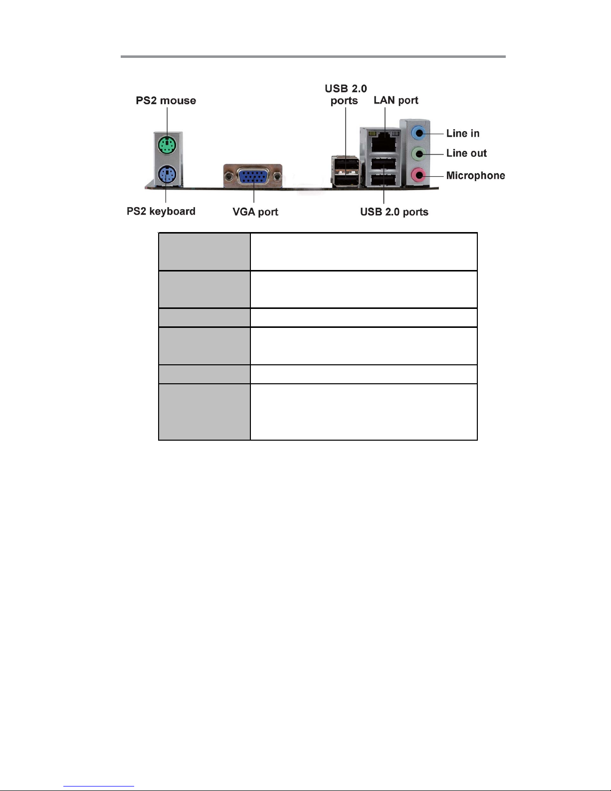
There is an advanced full set of I/O ports in the rear panel, including PS/2 mouse and
keyboard connectors, one D-sub (VGA) port, four USB 2.0 ports, one LAN port,
three audio jacks for microphone, line-in and 6-ch line-out. This motherboard is
designed in a Micro ATX form factor using a four-layer printed circuit board and
measures 230 mm x 180 mm.
Note: This board supports CPU up to 100W TDP only.
Key Features
The key features of this motherboard include:
Socket-FM1 Processor Support
• Supports socket FM1 for AMD A series processor
• Supports HyperTransport
TM
(HT) 3.0 interface Speeds
HyperTransport
TM
technology is a point-to-point link between two devices, it
enables integrated circuits to exchange information at much higher speeds than
currently available interconnect technologies.
Note: *1.Due to the limitation of chipset spec, it supports up to 1866 MHz for
motherboard with a single DIMM per channel.
Page 5

2
Motherboard User’s Guide
Chipset
The AMD A55 (Hudson D2) chipset is based on an innovative and scalable architecture with proven reliability and performance.
• Supports one PCI Express x1 slot
• Supports one PCI Express x16 for Graphics Interface, fully compliant to
the PCI Express Base Specification revision 2.0
• Compliant with PCI v2.3 interface at 33 MHz
• Supports four Serial ATA devices which speeds up to 3.0Gb/s
• Integrated USB 2.0 Host Controller supporting up to eight USB 2.0 ports
• Supports integrated RAID0, RAID1 and RAID10 (requires use of 4 or
more SATA ports) functionalities across all 4 ports
• Supports ACPI states S1, S3, S4 and S5
Audio
• 5.1 +2 Channel High Definition Audio Codec
• Meets Microsoft WLP3.x (Windows Logo Program) audio Requirements
• All DACs supports 44.1k/48k/96k/192kHz sample rate
• Software selectable 2.5V/3.2V/4.0V VREFOUT
• Direct Sound 3D
TM
compatible
• Power Support: Digital: 3.3V; Analog: 5V
Expansion Slots
• One PCI Express x16 slot
• One PCI Express x 1 slot
• One 32-bit PCI v2.3 complianat slot
Memory Support
• DDR3 1866
*1
/1600/1333 DDR3 SDRAM with Dual-channel supported
• Accommodates two unbuffered DIMMs
• Up to 16 GB per DIMM with maximum memory size up to 32 GB
Serial ATA
• Four Serial ATA Connectors
• Transfer rate exceeding best ATA (3.0 Gb/s) with scalability to higher rates
• Low pin count for both host and devices
Note: *1.Due to the limitation of chipset spec, it supports up to 1866 MHz for
motherboard with a single DIMM per channel.
Page 6

3
Chapter 1: Introduction
BIOS Firmware
The motherboard uses AMI BIOS that enables users to configure many
system features including the following:
• Power management
• Wake-up alarms
• CPU parameters
• CPU and memory timing
The firmware can also be used to set parameters for different processor clock
speeds.
Onboard I/O Ports
• PS/2 mouse and keyboard connectors
• One D-sub (VGA) port
• Four USB 2.0 ports
• One LAN port
• Audio jacks for microphone, line-in and 6-ch line-out
Onboard LAN (optional)
• Supports PCI Express
TM
1.1
• Integrated 10/100 transceiver
• Wake-on-LAN and remote wake-up support
• Supports PCI Express
TM
1.1
• Integrated 10/100/1000 transceiver
• Wake-on-LAN and remote wake-up support
Dimensions
• Micro ATX form factor of 230 x 180 mm
Note: Hardware specifications and software items are subject to change with
out notification.
Page 7

4
Motherboard User’s Guide
Package Contents
Your motherboard package ships with the following items:
The motherboard
Two Serial ATA cables
The Software support disk
Optional Accessories
You can purchase the following optional accessories for this motherboard.
The Extended USB module
The Serial ATA cable
Note: You can purchase your own optional accessories from the third party,
but please contact your local vendor on any issues of the specification
and compatibility.
Page 8

5
Chapter 2: Motherboard Installation
Chapter 2 Motherboard Installation
To install this motherboard in a system, please follow these instructions in this
chapter:
Identify the motherboard components
Install a CPU
Install one or more system memory modules
Make sure all jumpers and switches are set correctly
Install this motherboard in a system chassis (case)
Connect any extension brackets or cables to headers/connectors on the
motherboard
Install peripheral devices and make the appropriate connections to
headers/connectors on the motherboard
Note:
1 Before installing this motherboard, make sure jumper CLR_CMOS is
under Normal setting. See this chapter for information about locating
CLR_CMOS and the setting options.
2 Never connect power to the system during installation; otherwise, it
may damage the motherboard.
Page 9
6
Motherboard User’s Guide
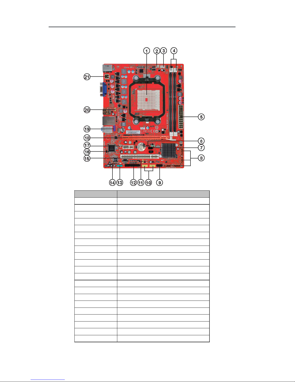
Motherboard Components
LABEL COMPONENTS
1. CPU SOCKET FM1 for AMD A series processors
2. SYS_FAN System cooling fan connector
3. CPU_FAN CPU cooling fan connector
4. DDR3_1~2 240-pin DDR3 SDRAM slots
5. ATX_POWER Standard 24-pin ATX power connector
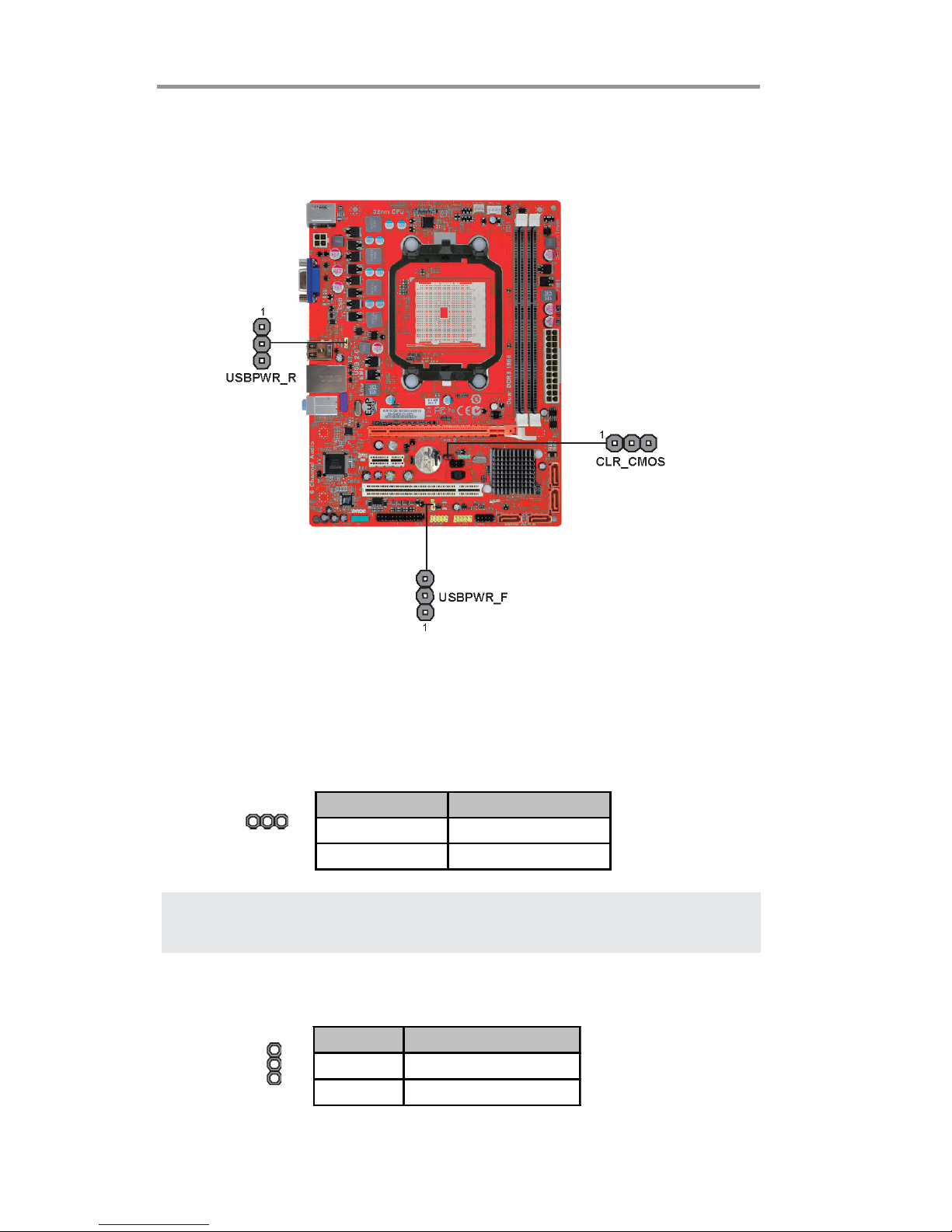
6. CLR_CMOS Clear CMOS jumper
7. SPK Speaker header
8. SATA1~4 Serial ATA 3.0 Gb/s connectors
9. F_PANEL Front panel switch/LED header
10. F_USB1~2 Front Panel USB 2.0 headers
11. USBPWR_F Front panel USB power select jumper
12. LPT Onboard parallel port header
13. COM Onboard serial port header
14. SPDIFO SPDIF out header
15. PCI 32-bit add-on card slots
16. CASE1 Chassis detect jumper
17. PCIE1 PCI Express x1 slot
18. PCIEX16 PCI Express x16 slot for graphics interface
19. F_AUDIO Front panel audio header
20. USBPWR_R Rear USB/PS2 power select jumper
21. ATX12V 4-pin +12V power connector
Page 10
7
Chapter 2: Motherboard Installation
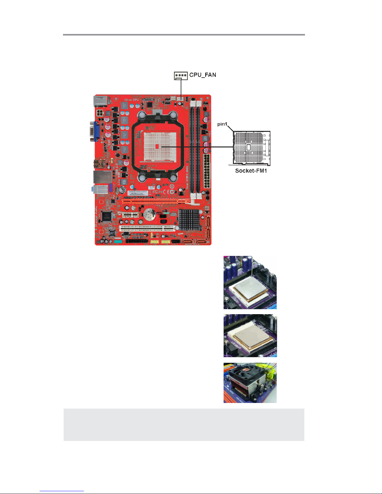
Installing the Processor
This motherboard has a socket FM1 processor socket. When choosing a processor,
consider the performance requirements of the system. Performance is based on the
processor design, the clock speed and system bus frequency of the processor, and
the quantity of internal cache memory and external cache memory.
PS/2 Mouse
Use the upper PS/2 port to connect a PS/2
pointing device.
PS/2 Keyboard
Use the lower PS/2 port to connect a PS/2
keyboard.
VGA P o r t
Connect your monitor to the VGA port.
LAN Port
Connect an RJ-45 jack to t he LAN port
to connect your computer t o the Network.
USB 2.0 Port s
Use the USB ports to connect USB devices.
Audio P ort s
Use the three audio ports to connect audio
devices. The first jack is for stereo line-in
signal. T he t hird jack is for microphone.
Page 11
8
Motherboard User’s Guide
CPU Installation Procedure
Follow these instructions to install the CPU:
1 Unhook the locking lever of the CPU socket.
Pull the locking lever away from the socket
and raising it to the upright position.
2 Match the pin1 corner marked as the beveled
edge on the CPU with the pin1 corner on the
socket. Insert the CPU into the socket. Do
not use force.
3 Push the locking lever down and hook it un-
der the latch on the edge of socket.
4 Apply thermal grease to the top of the CPU.
5 Install the cooling fan/heatsink unit onto the
CPU, and secure them all onto the socket
base.
6 Plug the CPU fan power cable into the CPU
fan connector (CPU_FAN) on the
motherboard.
Note: To achieve better airflow rates and heat dissipation, we suggest that
you use a high quality fan with 4800 rpm at least. CPU fan and heatsink
installation procedures may vary with the type of CPU fan/heatsink
supplied. The form and size of fan/heatsink may also vary.
*For reference only
Page 12
9
Chapter 2: Motherboard Installation
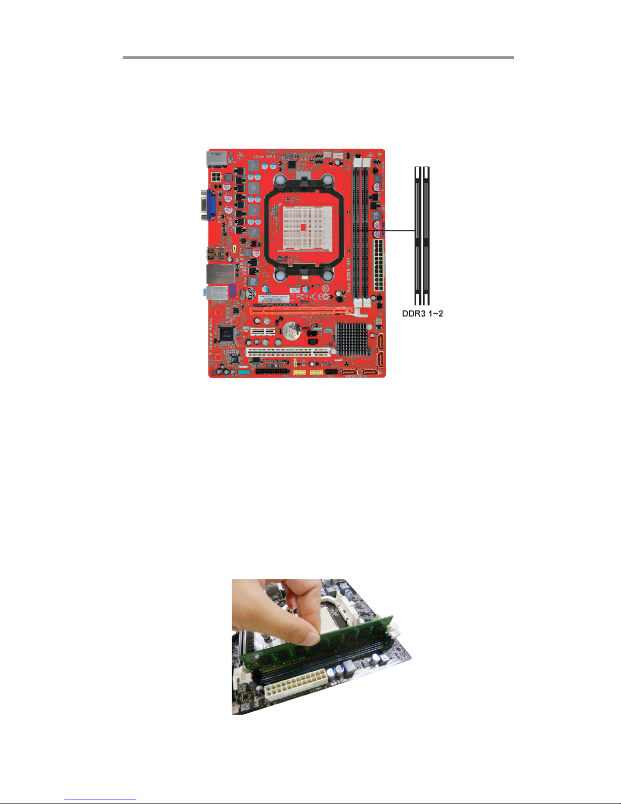
Installing Memory Modules
This motherboard accommodates two 240-pin DIMM sockets (Dual Inline Memory
Module) for unbuffered DDR3 1866/1600/1333 memory modules (Double Data
Rate SDRAM), and maximum 32 GB installed memory.
Memory Module Installation Procedure
These modules can be installed with up to 32 GB system memory. Refer to the
following to install the memory module.
1. Push down the latches on both sides of the DIMM socket.
2. Align the memory module with the socket. There is a notch on the DIMM
socket that you can install the DIMM module in the correct direction.
Match the cutout on the DIMM module with the notch on the DIMM
socket.
3. Install the DIMM module into the socket and press it firmly down until it
is seated correctly. The socket latches are levered upwards and latch on to
the edges of the DIMM.
4. Install any remaining DIMM modules.
*For reference only
Page 13
10
Motherboard User’s Guide
CLR_CMOS: Clear CMOS Jumper
Use this jumper to clear the contents of the CMOS memory. You may need to clear
the CMOS memory if the settings in the Setup Utility are incorrect and prevent
your motherboard from operating. To clear the CMOS memory, disconnect all the
power cables from the motherboard and then move the jumper cap into the CLEAR
setting for a few seconds.
Jumper Settings
Connecting two pins with a jumper cap is SHORT; removing a jumper cap from
these pins, OPEN.
Note: To avoid the system unstability after clearing CMOS, we recommend
users to enter the main BIOS setting page to “Load Optimal De-faults”
and then “Save Changes and Exit”.
Function Jumper Setting
VCC Short Pins 1-2
5VSB Short Pins 2-3
Use this jumper to set the Front Panel USB Power function.
USBPWR_F: FRONT PANEL USB POWER SELECT Jumper
Function Jumper Setting
NORMAL CMOS Short Pins 1-2
CLEA R Short Pins 2-3
CLR_CMOS
1
USBPWR_F
1
Page 14
11
Chapter 2: Motherboard Installation
Install The Motherboard
Install the motherboard in a system chassis (case). The board is a Micro ATX size
motherboard. You can install this motherboard in an ATX case. Make sure your
case has an I/O cover plate matching the ports on this motherboard.
Install the motherboard in a case. Follow the case manufacturer’s instructions to
use the hardware and internal mounting points on the chassis.
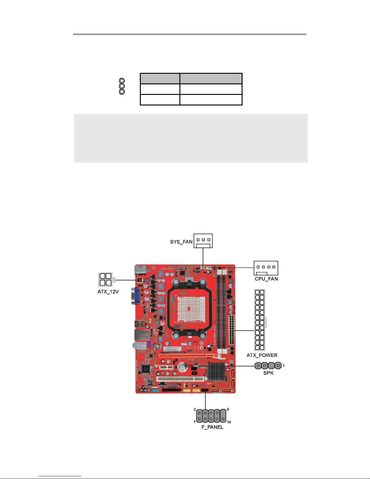
Note: 1. Make sure the power supply provides enough SB5V voltage before
selecting the SB5V function.
2. To wake up the computer by USB/PS2 KB/Mouse in S3 status, users
have to place the USBPWR_F & USBPWR_R cap onto 2-3 pin instead of
1-2 as default, and then press into BIOS “power Management Setup”
page to choose the functions (USB/PS2KB/MS) you want to enable.
Function Jumper Setting
VCC Short Pins 1-2
5V SB Short Pins 2-3
USBPWR_R: REAR USB PS/2 POWER SELECT Jumper
Use this jumper to set the Rear USB PS/2 Power function.
USBPWR_R
1
Page 15
12
Motherboard User’s Guide
Connecting Optional Devices
Refer to the following for information on connecting the motherboard’s optional
devices:
Connect the CPU cooling fan cable to CPU_FAN. Connect the standard power
supply connector to ATX_POWER. Connect the case speaker cable to SPK. Con-
nect the cable from the cooling fan to the SYS_FAN fan power connector on the
motherboard. Connect the auxiliary case power supply connector to ATX_12V.
Connect the case switches and indicator LEDs to the F_PANEL.
Pin Signal Pin Signal
1 HD_ LED_ P(+ ) 2 FP PW R/ S LP( +)
3 HD_L ED_N( - ) 4 FP PWR/SLP(-)
5 RESET_ SW _N( - ) 6 PO WER_ SW _P( +)
7 RESET_ SW _P( +) 8 PO WER_ SW _ N( - )
9 RSV D_DNU 10 KEY
Page 16
13
Chapter 2: Motherboard Installation
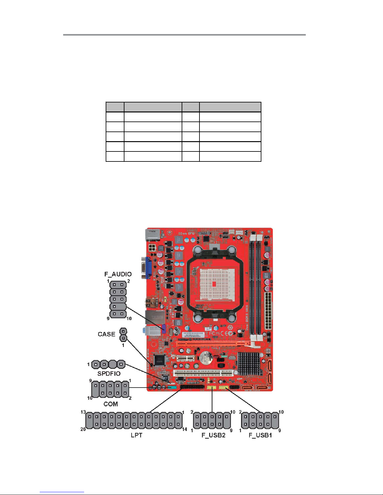
F_AUDIO: Front Panel Audio Header
This header allows the user to install auxiliary front-oriented microphone and lineout ports for easier access.
Here is a list of USB 2.0 pin assignments.
1. Locate the F_USB1~2 headers on the motherboard.
2. Plug the bracket cable onto the F_USB1~2 headers.
3. Remove a slot cover from one of the expansion slots on the system chassis.
Install an extension bracket in the opening. Secure the extension bracket to
the chassis with a screw.
Pin Signal Pin Signal
1 V ERG _ FP_ US BPW R0 2 V ERG _ FP_ US BPW R0
3 USB_FP_P0(-) 4 USB_FP_P1(- )
5 USB_FP_P0(+) 6 USB_FP_P1(+)
7 GROUND 8 GROUND
9KEY 10GROUND
F_USB1~2: Front Panel USB 2.0 Headers
The motherboard has USB 2.0 ports installed on the rear edge I/O port array.
Additionally, some computer cases have USB 2.0 ports at the front of the case. If
you have this kind of case, use auxiliary USB 2.0 headers F_USB1~2 to connect the
front-mounted ports to the motherboard.
CASE1: Chassis intrusion detect header
This detects if the chassis cover has been removed. This function needs a chassis
equipped with instrusion detection switch and needs to be enabled in BIOS.
Pin Signal Pin Signal
1 PORT1L 2 AUD_GND
3 PO RT1 R 4 PRES ENCE#
5 PORT2R 6 SENSE1_RETURN
7 S ENS E_S END 8 KEY
9 PO RT2 L 1 0 S ENSE2 _RETU RN
Pin 1-2 Function
Short Chassis cover is removed
Open Chassis cover is closed
Page 17

14
Motherboard User’s Guide
13 SLCT
26 K ey
LPT: Onboard parallel port header
This is a header that can ba used to connect to the printer, scanner or other devices.
1 STROBE
14 ALF
2 PD0
3 PD1
4 PD2
5 PD3
15 ERROR
16 INIT
17 SLCTIN
18 Ground
Pin Signal Name
Pin Signal Name
6 PD4
19 Ground
7 PD5
20 Ground
8 PD6
9 PD7
10 AC K
11 BUSK
12 PE
21 Ground
22 Ground
23 Ground
24 Ground
25 Ground
COM: Onboard serial port header
Connect a serial port extension bracket to this header to add a second serial port to
your system.
SPDIFO: SPDIF out header
This is an optional header that provides an S/PDIF (Sony/Philips Digital Interface)
output to digital multimedia device through optical fiber or coaxial connector.
Pin Signal
1SPDIF
2 +5VA
3Key
4GND
1 DCDB Data Carrier Detect
2 SINB Serial Input
3 SOUTB UART B Serial Output
4 DTRB UART B Data Terminal Ready
5 GND Ground
6 DSRB Data Set Ready
7 RTSB RART B Request to Send
8 CTSB Clear to Send
9 RI Ring Indicator
10 Key No pin
Pin Signal Name Function
Page 18
15
Chapter 2: Motherboard Installation
Install Other Devices
Install and connect any other devices in the system following the steps below.
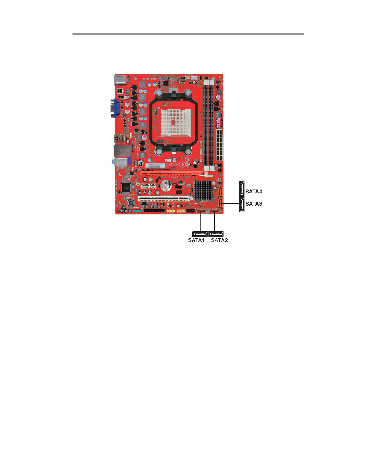
Serial ATA Devices
The Serial ATA (Advanced Technology Attachment) is the standard interface for
the IDE hard drives, which is designed to overcome the design limitations while
enabling the storage interface to scale with the growing media rate demands of PC
platforms. It provides you a faster transfer rate of 3.0 Gb/s. If you have installed a
Serial ATA hard drive, you can connect the Serial ATA cables to the Serial ATA hard
drive or the connector on the motherboard.
On the motherboard, locate the Serial ATA connectors SATA1-4, which support
Serial ATA devices, simpler disk drive cabling and easier PC assembly.
It eliminates limitations of the current Parallel ATA interface, but maintains register
compatibility and software compatibility with Parallel ATA.
Page 19
16
Motherboard User’s Guide
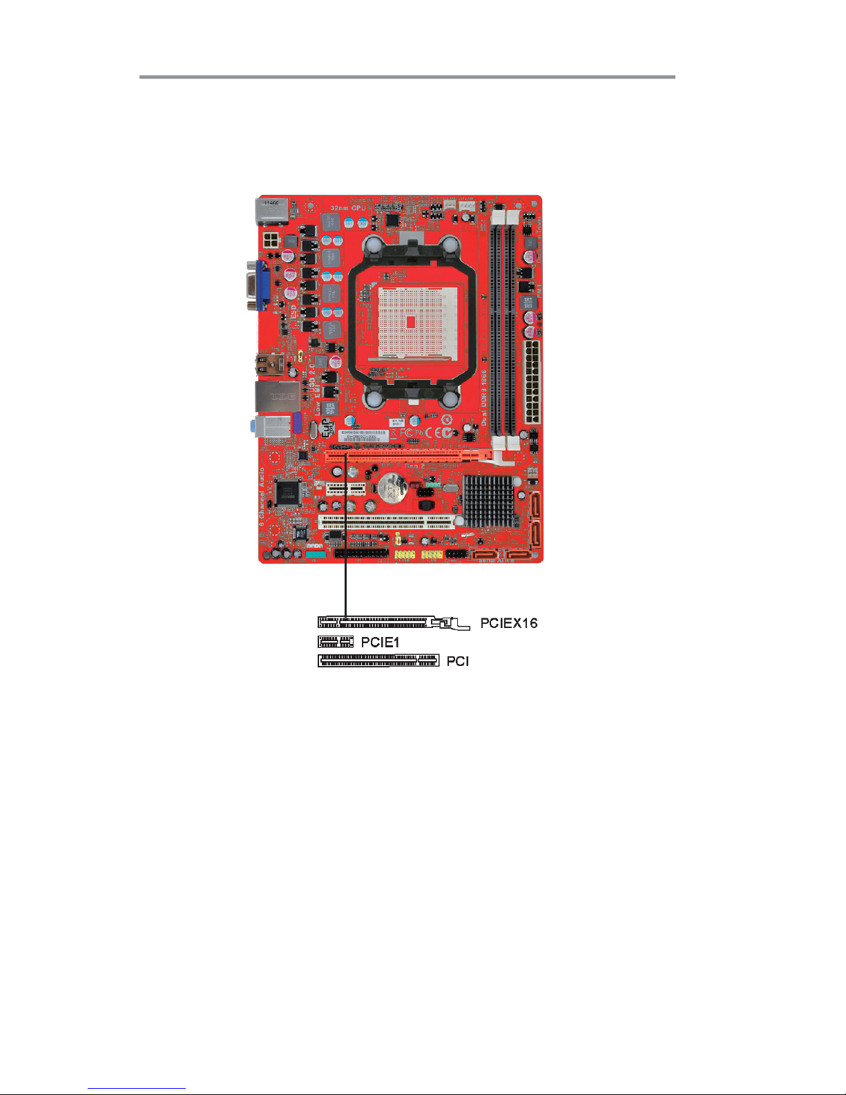
Expansion Slots
This motherboard has one PCI Express x16, one PCI Express x1 and one 32-bit
PCI slot.
Page 20

17
Chapter 2: Motherboard Installation
Follow the steps below to install an PCI Express x16/ PCI Express x1/PCI expansion card.
1. Locate the PCI Express x16, PCI Express x1, PCI slots on the mainboard.
2. Remove the blanking plate of the slot from the system chassis.
3. Install the edge connector of the expansion card into the slot. Ensure the
edge connector is correctly seated in the slot.
4. Secure the metal bracket of the card to the system chassis with a screw.
PCI Express x16 Slot
You can install an external PCI Express graphics card that is fully compliant to the
PCI Express Base Specification revsion 2.0.
PCI Slot
You can install the 32-bit PCI interface expansion card in the slot.
*For reference only
PCI Express x1 Slot
The PCI Express x 1 slot is fully compliant to the PCI Express Base Specification
revision 1.1 as well.
Page 21

18
Motherboard User’s Guide
Chapter 3 BIOS Setup Utility
Introduction
The BIOS Setup Utility records settings and information of your computer, such
as date and time, the type of hardware installed, and various configuration settings.
Your computer applies the information to initialize all the components when booting up and basic functions of coordination between system components.
If the Setup Utility configuration is incorrect, it may cause the system to malfunction. It can even stop your computer booting properly. If it happens, you can use
the clear CMOS jumper to clear the CMOS memory which has stored the configuration information; or you can hold down the Page Up key while rebooting your
computer. Holding down the Page Up key also clears the setup information.
You can run the setup utility and manually change the configuration. You might
need to do this to configure some hardware installed in or connected to the
motherboard, such as the CPU, system memory, disk drives, etc.
Running the Setup Utility
Every time you start your computer, a message appears on the screen before the
operating system loading that prompts you to “Hit <DEL>if you want to run
SETUP”. Whenever you see this message, press the Delete key, and the Main
menu page of the Setup Utility appears on your monitor.
You can use cursor arrow keys to highlight anyone of options on the main menu
page. Press Enter to select the highlighted option. Press the Escape key to leave
the setup utility. Press +/-/ to modify the selected field’s values.
Version 2.11.1210. Copyright (C) 2011, American Megatrends,
Inc.
BIOS Information
System Language [English]
System Date [Sun 02/12/2012]
System Time [02:10:11]
Choose the system default
language
Aptio Setup Utility - Copyright (C) 2011 American Megatrends, Inc.
Version 2.13.1216. Copyright (C) 2011, American Megatrends, Inc.
Main Advanced Chipset Tweak Boot Security Exit
: Select Screen
+/- : Change Opt.
lk
mn
/Click: Select Item
F1: General Help
F2: Previous Values
F3: Optimized Defaults
F4: Save & Exit
ESC/Right Click: Exit
Enter/Dbl Click : Select
Page 22

19
Chapter 3: BIOS Setup Utility
Some options on the main menu page lead to tables of items with installed values
that you can use cursor arrow keys to highlight one item, and press PgUp and PgDn
keys to cycle through alternative values of that item. The other options on the main
menu page lead to dialog boxes requiring your answer OK or Cancel by selecting the
[OK] or [Cancel] key.
If you have already changed the setup utility, press F10 to save those changes and
exit the utility. Press F1 to display a screen describing all key functions. Press F9
to load optimtimal settings.
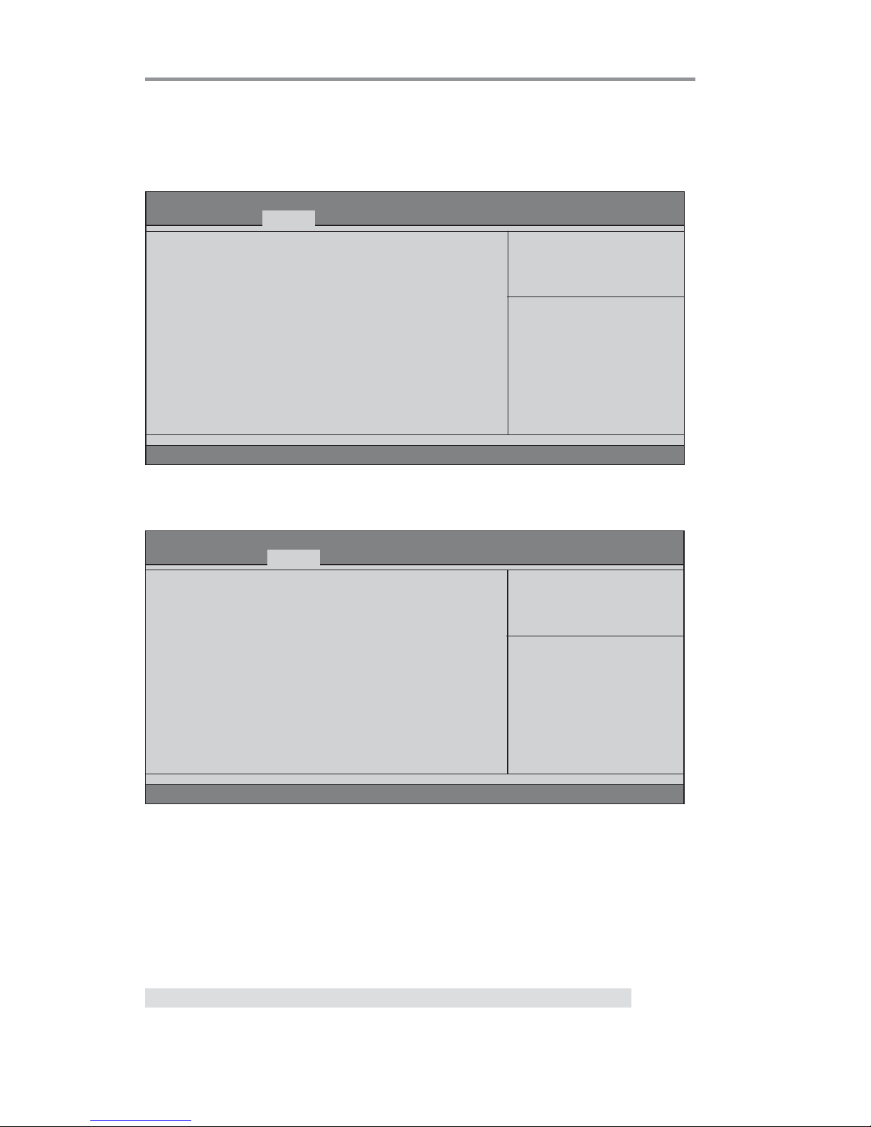
Main Menu
When you enter the BIOS Setup program, the main menu appears, giving you an
overview of the basic system information. Select an item and press <Enter> to
display the submenu.
Date & Time
The Date and Time items show the current date and time on the computer. If you are
running a Windows OS, these items are automatically updated whenever you make
changes to the Windows Date and Time Properties utility.
System Language (English)
This item is used to set system language.
Version 2.11.1210. Copyright (C) 2011, American Megatrends,
Inc.
BIOS Information
System Language [English]
System Date [Sun 02/12/2012]
System Time [02:10:11]
Choose the system default
language
Aptio Setup Utility - Copyright (C) 2011 American Megatrends, Inc.
Version 2.13.1216. Copyright (C) 2011, American Megatrends, Inc.
Main Advanced Chipset Tweak Boot Security Exit
: Select Screen
+/- : Change Opt.
lk
mn
/Click: Select Item
F1: General Help
F2: Previous Values
F3: Optimized Defaults
F4: Save & Exit
ESC/Right Click: Exit
Enter/Dbl Click : Select
Page 23

20
Motherboard User’s Guide
The Advanced menu items allow you to change the settings for the CPU and other
system.
Advaned Menu
Launch PXE OpROM (Disabled)
Use this item to enable or disable the PXE OpROM.
Version 2.13.1216. Copyright (C) 2011, American Megatrends, Inc.
Main
Advanced Chipset Tweak Boot Security Exit
Aptio Setup Utility - Copyright (C) 2011 American Megatrends, Inc.
Legacy OpROM Support
Launch PXE OpROM [Disabled]
Launch Storage OpROM [Enabled]
LAN Configuration
PC Health Status
Power Management Setup
ACPI Settings
CPU Configuration
SATA Configuration
USB Configuration
Super IO Configuration
ff
ff
f
ff
ff
f
ff
ff
f
ff
ff
f
ff
ff
f
ff
ff
f
ff
ff
f
ff
ff
f
: Select Screen
+/- : Change Opt.
lk
mn
/Click: Select Item
F1: General Help
F2: Previous Values
F3: Optimized Defaults
F4: Save & Exit
ESC/Right Click: Exit
Enter/Dbl Click : Select
Enable/Disable Onboard LAN
Option ROM
Launch Storage OpROM (Enabled)
Use this item to enable or disable the Storage OpROM.
Page 24

21
Chapter 3: BIOS Setup Utility
Onboard LAN Controller (Enabled)
Use this item to enable or disable the Onboard LAN.
Press <Esc> to return to the Advanced Menu page.
LAN Configuration
The item in the menu shows the LAN-related information that the BIOS automatically detects.
Aptio Setup Utility - Copyright (C) 2011 American Megatrends, Inc.
Version 2.02.1205. Copyright (C) 2010, American Megatrends,
Inc.
Main Advanced Chipset Tweak Boot Security Exit
Version 2.13.1216. Copyright (C) 2011, American Megatrends, Inc.
PC Health Status
On motherboards support hardware monitoring, this item lets you monitor the
paeameters for critical voltages, temperatures and fan speeds.
LAN Configuration
Onboard LAN Controller [Enabled]
Enabled or Disabled Onboard LAN
: Select Screen
+/- : Change Opt.
lk
mn
/Click: Select Item
F1: General Help
F2: Previous Values
F3: Optimized Defaults
F4: Save & Exit
ESC/Right Click: Exit
Enter/Dbl Click : Select
Main Advanced Chipset Tweak Boot Security Exit
Version 2.13.1216. Copyright (C) 2011, American Megatrends, Inc.
Aptio Setup Utility - Copyright (C) 2011 American Megatrends, Inc.
PC Health Status
Smart Fan Function
CPU Tct1 : +34
CPU Fan Speed : 956 RPM
SYS Fan Speed : N/A
CPU Voltage : +1.216 V
DIMM Voltage : +1.608 V
FCH Voltage : +1.168 V
ff
ff
f
: Select Screen
+/- : Change Opt.
lk
mn
/Click: Select Item
F1: General Help
F2: Previous Values
F3: Optimized Defaults
F4: Save & Exit
ESC/Right Click: Exit
Enter/Dbl Click : Select
Page 25

22
Motherboard User’s Guide
Scroll to this item and press <Enter> to view the following screen:
fSmart Fan Function
Smart Fan Mode (Normal)
This item allows you to select the fan mode (Normal, Quiet, Silent, or Manual) for a
better operation environment. If you choose Normal mode, the fan speed will be auto
adjusted depending on the CPU temperature. If you choose Quite mode, the fan speed
will be auto minimized for quiet environment. If you choose Silent mode, the fan speed
will be auto restricted to make system more quietly. If you choose Manual mode, the
fan speed will be adjust depending on users’ parameters.
CPU SMART Fan Control (Enabled)
This item allows you to enable/disable the control of the CPU fan speed by changing
the fan voltage.
Aptio Setup Utility - Copyright (C) 2011 American Megatrends, Inc.
Version 2.13.1216. Copyright (C) 2011, American Megatrends, Inc.
Main
Advanced Chipset Tweak Boot Security Exit
CPU Smart Fan Control [Enabled]
Smart Fan Mode [Normal]
Smart Fan Start Offset (-) 37
Tolerance Value 3
StartUp Value 102
Stop Value 77
: Select Screen
+/- : Change Opt.
lk
mn
/Click: Select Item
F1: General Help
F2: Previous Values
F3: Optimized Defaults
F4: Save & Exit
ESC/Right Click: Exit
Enter/Dbl Click : Select
Aptio Setup Utility - Copyright (C) 2011 American Megatrends, Inc.
Version 2.13.1216. Copyright (C) 2011, American Megatrends, Inc.
Main
Advanced Chipset Tweak Boot Security Exit
CPU Smart Fan Control [Enabled]
Smart Fan Mode [Quiet]
Smart Fan Start Offset (-) 45
Tolerance Value 5
StartUp Value 90
Stop Value 64
: Select Screen
+/- : Change Opt.
lk
mn
/Click: Select Item
F1: General Help
F2: Previous Values
F3: Optimized Defaults
F4: Save & Exit
ESC/Right Click: Exit
Enter/Dbl Click : Select
Page 26

23
Chapter 3: BIOS Setup Utility
Aptio Setup Utility - Copyright (C) 2011 American Megatrends, Inc.
Version 2.13.1216. Copyright (C) 2011, American Megatrends, Inc.
Main
Advanced Chipset Tweak Boot Security Exit
CPU Smart Fan Control [Enabled]
Smart Fan Mode [Silent]
Smart Fan Start Offset (-) 52
Tolerance Value 7
StartUp Value 77
Stop Value 51
: Select Screen
+/- : Change Opt.
lk
mn
/Click: Select Item
F1: General Help
F2: Previous Values
F3: Optimized Defaults
F4: Save & Exit
ESC/Right Click: Exit
Enter/Dbl Click : Select
Press <Esc> to return to the PC Health Status page.
Aptio Setup Utility - Copyright (C) 2011 American Megatrends, Inc.
Version 2.13.1216. Copyright (C) 2011, American Megatrends, Inc.
Main
Advanced Chipset Tweak Boot Security Exit
CPU Smart Fan Control [Enabled]
Smart Fan Mode [Manual]
Smart Fan Start Offset (-) 37
Tolerance Value 3
StartUp Value 102
Stop Value 51
: Select Screen
+/- : Change Opt.
lk
mn
/Click: Select Item
F1: General Help
F2: Previous Values
F3: Optimized Defaults
F4: Save & Exit
ESC/Right Click: Exit
Enter/Dbl Click : Select
Smart Fan Start Offset (-) (37)
This item is used to set the start temperature of the smart fan.
Tolerance Value (3)
This item specifies the temperature tolerance value of the smart fan.
StartUp Value (102)
This item specifies the start PWM of the smart fan when the temperature is between
the start temperature plus tolerance value and start temperature minus tolerance value.
Stop Value (77)
This item specifies the PWM of the smart fan when the temperature is lower than the
start temperature minus tolerance value.
Page 27

24
Motherboard User’s Guide
System Component Characteristics
These items display the monitoring of the overall inboard hardware health events,
such as System & CPU temperature, CPU & DIMM voltage, CPU & system fan
speed,... etc.
• CPU Tct1
• CPU Fan Speed
• SYS Fan Speed
• CPU Voltage
• DIMM Voltage
• FCH Voltage
Press <Esc> to return to the Advanced Menu page.
Page 28

25
Chapter 3: BIOS Setup Utility
EUP Function (Enabled)
This item allows user to enable or disable EUP support.
Resume By PS2 MS (S3) (Disabled)
This item enables or disables you to allow mouse activity to awaken the system from
power saving mode.
Power Management Setup
This page sets up some parameters for system power management operation.
Resume By PME (Disabled)
The system can be turned off with a software command. If you enable this item, the
system can automatically resume if there is an incoming call on the PCI Modem or
PCI LAN card. You must use an ATX power supply in order to use this feature. Use this
item to do wake-up action if inserting the PCI card.
Resume By RING (Disabled)
The system can be turned off with a software command. If you enable this item, the
system can automatically resume if there is an incoming call on the Modem. You must
use an ATX power supply in order to use this feature.
Resume By PS2 KB (S3) (Disabled)
This item enables or disables you to allow keyboard activity to awaken the system
from power saving mode.
Power LED Type (Dual Color LED)
This item shows the type of the power LED.
Resume By USB 1.x/2.0 (S3) (Disabled)
This item allows you to enable/disable the USB 1.x/2.0 device wakeup function from
S3 mode.
Press <Esc> to return to the Advanced Menu page.
Aptio Setup Utility - Copyright (C) 2011 American Megatrends, Inc.
Main
Advanced Chipset Tweak Boot Security Exit
Version 2.13.1216. Copyright (C) 2011, American Megatrends, Inc.
Power Management Setup
Resume By RING Disabled]
Resume By PME [Disabled]
Resume By USB 1.x/2.0 (S3) [Disabled]
Resume By PS2 KB (S3) [Disabled]
Resume By PS2 MS (S3) [Disabled]
EUP Function [Enabled]
Power LED Type [Dual Color LED]
About Resume by RING
: Select Screen
+/- : Change Opt.
lk
mn
/Click: Select Item
F1: General Help
F2: Previous Values
F3: Optimized Defaults
F4: Save & Exit
ESC/Right Click: Exit
Enter/Dbl Click : Select
Page 29

26
Motherboard User’s Guide
ACPI Setting
The item in the menu shows the highest ACPI sleep state when the system enters
suspend.
ACPI Sleep State (S3(Suspend to RAM))
This item allows user to enter the ACPI S3 (Suspend toRAM) Sleep State (default).
Press <Esc> to return to the Advanced Menu page.
CPU Configuration
Scroll to this item and press <Enter> to view the following screen:
Aptio Setup Utility - Copyright (C) 2011 American Megatrends, Inc.
Version 2.13.1216. Copyright (C) 2011, American Megatrends, Inc.
Main
Advanced Chipset Tweak Boot Security Exit
ACPI Setting
ACPI Sleep State [S3 (Suspend to RAM)]
Select the highest ACPI sleep
state the system will enter
when the Suspend button is
pressed.
: Select Screen
+/- : Change Opt.
lk
mn
/Click: Select Item
F1: General Help
F2: Previous Values
F3: Optimized Defaults
F4: Save & Exit
ESC/Right Click: Exit
Enter/Dbl Click : Select
Aptio Setup Utility - Copyright (C) 2011 American Megatrends, Inc.
Version 2.13.1216. Copyright (C) 2011, American Megatrends, Inc.
Main Advanced Chipset Tweak Boot Security Exit
CPU Configuration
Node0: AMD Engineering Sample
Max Speed: 2300 MHZ
Microcode Patch Level: 3000029
--------- Cache per Core --------L1 Instruction Cache: 64 KB/2-way
L1 Data Cache: 64KB/2-way
L2 Cache: 512KB/16-way
No L3 Cache Present
C6 Mode [Enabled]
CPB Mode [Auto]
AMD C&Q [Enabled]
SB Spread Spectrum [Enabled]
Enable/disable C6
: Select Screen
+/- : Change Opt.
lk
mn
/Click: Select Item
F1: General Help
F2: Previous Values
F3: Optimized Defaults
F4: Save & Exit
ESC/Right Click: Exit
Enter/Dbl Click : Select
Page 30

27
Chapter 3: BIOS Setup Utility
Press <Esc> to return to the Advanced Menu page.
Max Speed (2300 MHz)
This item shows the maximum & intended speed of the CPU.
Microcode Patch Level (3000029)
This item shows the Microcode revision.
L1 Instruction Cache (64KB/2-way)
This item shows CPU L1 Cache.
L2 Cache (512KB/16-way)
This item shows CPU L2 Cache.
No L3 Cache Present
This item shows CPU L3 Cache.
L1 Data Cache (64KB/2-way)
This item shows CPU L1 Cache.
C6 Mode (Enabled)
This item enables or disables the C6 mode.
CPB Mode (Auto)
This item is used to set the CPB mode.
AMD C&Q (Enabled)
This item enables or disables the CPU C&Q Function.
SB Spread Spectrum (Enabled)
This item enables or disables the SB Clock Spread Spectrum.
Page 31

28
Motherboard User’s Guide
SATA Configuration
Use this item to show the mode of serial SATA configuration options.
Serial-ATA Controller (Enabled)
Use this item to select the Serial-ATA controller options: Disabled, Compatible, Enabled.
SATA Port1~4 (WDC WD5000AAKX (500.1/Not Present)
This motherboard supports four SATA channels and each channel allows one SATA
device to be installed. Use these items to configure each device on the SATA channel,
and each channel allows one SATA device to be installed.
SATA Mode (IDE Mode)
Use this item to select SATA mode.
Press <Esc> to return to the Advanced Menu page.
Aptio Setup Utility - Copyright (C) 2011 American Megatrends, Inc.
Version 2.13.1216. Copyright (C) 2011, American Megatrends, Inc.
Main Advanced Chipset Tweak Boot Security Exit
SATA Configuration
Serial-ATA Controller [Enabled]
SATA Mode [IDE Mode]
SATA Port1 WDC WD5000AAKX (500.1
SATA Port2 Not Present
SATA Port3 Not Present
SATA Port4 Not Present
: Select Screen
+/- : Change Opt.
lk
mn
/Click: Select Item
F1: General Help
F2: Previous Values
F3: Optimized Defaults
F4: Save & Exit
ESC/Right Click: Exit
Enter/Dbl Click : Select
Page 32

29
Chapter 3: BIOS Setup Utility
USB Configuration
Scroll to this item and press <Enter> to view the following screen:
All USB Devices (Enabled)
Use this item to enable or disable all USB devices.
Legacy USB Support (Enabled)
Use this item to enable or disable support for legacy USB devices. Setting toAudio
allows the system to detect the presence of the USB device at startup. If detected, the
USB controller legacy mode is enabled. If no USB device is detected, the legacy USB
support is disabled.
Aptio Setup Utility - Copyright (C) 2011 American Megatrends, Inc.
Version 2.13.1216. Copyright (C) 2011, American Megatrends, Inc.
Main
Advanced Chipset Tweak Boot Security Exit
Press <Esc> to return to the Advanced Menu page.
USB Configuration
All USB Devices [Enabled]
Legacy USB Support [Enabled]
: Select Screen
+/- : Change Opt.
lk
mn
/Click: Select Item
F1: General Help
F2: Previous Values
F3: Optimized Defaults
F4: Save & Exit
ESC/Right Click: Exit
Enter/Dbl Click : Select
Page 33

30
Motherboard User’s Guide
Super IO Configuration
Scroll to this item and press <Enter> to view the following screen:
Aptio Setup Utility - Copyright (C) 2011 American Megatrends, Inc.
Main
Advanced Chipset Tweak Boot Security Exit
Version 2.13.1216. Copyright (C) 2011, American Megatrends, Inc.
Super IO Configuration
Serial Port 0 Configutation
Parallel Port Configutation
ff
ff
f
Set Parameters of Serial Port
0 (COMA)
: Select Screen
+/- : Change Opt.
lk
mn
/Click: Select Item
F1: General Help
F2: Previous Values
F3: Optimized Defaults
F4: Save & Exit
ESC/Right Click: Exit
Enter/Dbl Click : Select
ff
ff
f
: Select Screen
+/- : Change Opt.
lk
mn
/Click: Select Item
F1: General Help
F2: Previous Values
F3: Optimized Defaults
F4: Save & Exit
ESC/Right Click: Exit
Enter/Dbl Click : Select
fSerial Port 0 Configuration
Scroll to this item and press <Enter> to view the following screen:
Serial Port (Enabled)
This item allows you to enable or disable serial port.
Device Settings (IO=3F8h; IRQ=4)
This item shows the information of the device settings.
Change Settings (Auto)
Use this item to change device settings.
Serial Port 0 Configuration
Serial Port [Enabled]
Device Settings IO=3F8h; IRQ=4;
Aptio Setup Utility - Copyright (C) 2011 American Megatrends, Inc.
Version 2.13.1216. Copyright (C) 2011, American Megatrends, Inc.
Select an optional setting for
Super IO device.
Change Settings [Auto]
Main
Advanced Chipset Tweak Boot Security Exit
Press <Esc> to return to the Super IO Configuration page.
Change Settings
Auto
IO=3F8h; IRQ=4
IO=3F8h; IRQ=3,4,5,6,7,9,10,11,12;
IO=2F8h; IRQ=3,4,5,6,7,9,10,11,12;
IO=3E8h; IRQ=3,4,5,6,7,9,10,11,12;
IO=2E8h; IRQ=3,4,5,6,7,9,10,11,12;
Main Advanced Chipset Tweak Boot Security Exit
Page 34

31
Chapter 3: BIOS Setup Utility
fParallel Port Configuration
Scroll to this item and press <Enter> to view the following screen:
Press <Esc> to return to the Advanced Menu page.
Parallel Port Configuration
Parallel Port [Enabled]
Device Settings IO=378h; IRQ=5;
Aptio Setup Utility - Copyright (C) 2011 American Megatrends, Inc.
Version 2.13.1216. Copyright (C) 2011, American Megatrends, Inc.
Select an optional setting for
Super IO device.
Change Settings [Auto]
Device Mode [STD Printer Mode]
Main Advanced Chipset Tweak Boot Security Exit
Change Settings
Auto
IO=3F8h; IRQ=4
IO=3F8h; IRQ=3,4,5,6,7,9,10,11,12;
IO=2F8h; IRQ=3,4,5,6,7,9,10,11,12;
IO=3E8h; IRQ=3,4,5,6,7,9,10,11,12;
IO=2E8h; IRQ=3,4,5,6,7,9,10,11,12;
: Select Screen
+/- : Change Opt.
lk
mn
/Click: Select Item
F1: General Help
F2: Previous Values
F3: Optimized Defaults
F4: Save & Exit
ESC/Right Click: Exit
Enter/Dbl Click : Select
Parallel Port (Enabled)
This item allows you to enable or disable parallel port.
Device Settings (IO=378h; IRQ=5;)
This item shows the information of the device settings.
Change Settings (Auto)
Use this item to change device settings.
Device Mode (STD Printer Mode)
Use this item to select device mode.
Parallel Port Configuration
Parallel Port [Enabled]
Device Settings IO=378h; IRQ=5;
Aptio Setup Utility - Copyright (C) 2011 American Megatrends, Inc.
Version 2.13.1216. Copyright (C) 2011, American Megatrends, Inc.
Change the Printer Port mode.
Change Settings [Auto]
Device Mode [STD Printer Mode]
Main Advanced Chipset Tweak Boot Security Exit
Device Mode
STD Printer Mode
SPP Mode
EPP-1.9 and SPP Mode
EPP-1.7 and SPP Mode
ECP Mode
ECP and EPP 1.9 Mode
ECP and EPP 1.7 Mode
: Select Screen
+/- : Change Opt.
lk
mn
/Click: Select Item
F1: General Help
F2: Previous Values
F3: Optimized Defaults
F4: Save & Exit
ESC/Right Click: Exit
Enter/Dbl Click : Select
Press <Esc> to return to the Super IO Configuration page.
Page 35
32
Motherboard User’s Guide
fNorth Bridge
Scroll to this item and press <Enter> and view the following screen:
The chipset menu items allow you to change the settings for the North chipset,
South chipset and other system.
Chipset Menu
Aptio Setup Utility - Copyright (C) 2011 American Megatrends, Inc.
Version 2.13.1216. Copyright (C) 2011, American Megatrends, Inc.
North Bridge Parameters
North Bridge
South Bridge
f
f
Main Advanced Chipset Tweak Boot Security Exit
Aptio Setup Utility - Copyright (C) 2011 American Megatrends, Inc.
Version 2.13.1216. Copyright (C) 2011, American Megatrends, Inc.
Main Advanced Chipset Tweak Boot Security Exit
North Bridge
IGD Memory [Auto]
Initate Graphic Adapter [PCI Express]
CrossFire [Enabled]
IGD Share Memory Size
IGD Memory (Auto)
This item shows the information of the IGD(Internal Graphics device) memory.
Initate Graphic Adapter (PCI Express)
This item allows you to select graphics controller to use as the primary boot device.
: Select Screen
+/- : Change Opt.
lk
mn
/Click: Select Item
F1: General Help
F2: Previous Values
F3: Optimized Defaults
F4: Save & Exit
ESC/Right Click: Exit
Enter/Dbl Click : Select
: Select Screen
+/- : Change Opt.
lk
mn
/Click: Select Item
F1: General Help
F2: Previous Values
F3: Optimized Defaults
F4: Save & Exit
ESC/Right Click: Exit
Enter/Dbl Click : Select
CrossFire (Enabled)
This item allows you to enable or disable CrossFire function.
Press <Esc> to return to the Chipset Menu page.
Page 36

33
Chapter 3: BIOS Setup Utility
fSouth Bridge
Scroll to this item and press <Enter> to view the following screen:
Restore AC Power Loss (Power Off)
This item enables your computer to automatically restart or return to its operating
status.
Audio Configuration
This item shows the information of the audio configuration.
Azalia HD Audio (Enabled)
This item enables or disables Azalia HD audio.
Case Open Warning (Disabled)
This item enables or disables the warning if the case is opened up, and the item below
indicates the current status of the case.
Chassis Opened (No)
This item indicates whether the case has been opened.
Aptio Setup Utility - Copyright (C) 2011 American Megatrends, Inc.
Version 2.13.1216. Copyright (C) 2011, American Megatrends, Inc.
Specify what state to go to
when power is re-applied after
a power failure (G3 state).
South Bridge
Restore AC Power Loss [Power Off]
Audio Configuration
Azalia HD Audio [Enabled]
Case Open Warning [Disabled]
Chassis Opened [No]
Main Advanced Chipset Tweak Boot Security Exit
: Select Screen
+/- : Change Opt.
lk
mn
/Click: Select Item
F1: General Help
F2: Previous Values
F3: Optimized Defaults
F4: Save & Exit
ESC/Right Click: Exit
Enter/Dbl Click : Select
Press <Esc> to return to the Chipset Menu page.
Page 37

34
Motherboard User’s Guide
This page enables you to set the clock speed and system bus for your system. The
clock speed and system bus are determined by the kind of processor you have
installed in your system.
Tweak Menu
CPU Ratio/Voltage [Auto]
Memory Clock [Auto]
Memory Timing Configuration [Auto]
Memory Clock DCT0 is : None
Command Rate N /A
CAS# Latency (tCL) N/A
RAS# to CAS# Delay (tRCD) N/A
Row Precharge Time (tRP) N/A
RAS# Active Time (tRAS) N/A
Memory Clock DCT1 is : (DDR-1333/667Mhz)
Command Rate 1 T
CAS# Latency (tCL) 9 CLK
RAS# to CAS# Delay (tRCD) 9 CLK
Row Precharge Time (tRP) 9 CLK
RAS# Active Time (tRAS) 24 CLK
CPU Over-clocking Func. [Disabled]
IGD Over-clocking Func. [Disabled]
Main Advanced Chipset Tweak Boot Security Exit
Aptio Setup Utility - Copyright (C) 2011 American Megatrends, Inc.
Version 2.13.1216. Copyright (C) 2011, American Megatrends, Inc.
: Select Screen
+/- : Change Opt.
lk
mn
/Click: Select Item
F1: General Help
F2: Previous Values
F3: Optimized Defaults
F4: Save & Exit
ESC/Right Click: Exit
Enter/Dbl Click : Select
RAS# to CAS# Delay (tRCD) (N/A/9 CLK)
These items specify the RAS# to CAS# delay to Rd/Wr command to the same bank.
RAS# Active Time (tRAS) (N/A/24 CLK)
These items specify the RAS# active time.
Row Precharge Time (tRP) (N/A/9 CLK)
These items specify Row precharge to Active or Auto-Refresh of the same bank.
Memory Timing Configuration
This item shows the information of Memory Timing Configuration.
CAS#Latency(tCL) (N/A/9 CLK)
These items determine the operation of DDR SDRAM memory CAS(column address
strobe). It is recommanded that you leave this item at the default value. The 2T setting
requires faster memory that specifically supports this mode.
Command Rate (N/A/1 T)
These items allow users to set command rate.
CPU Ratio/Voltage (Auto)
This item is used to set the CPU Ratio/Voltage.
Memory Clock (Auto)
This item is used to set the memory clock.
Memory Clock DCT0 is : (None)
This item shows current memory clock of DCT0.
Page 38

35
Chapter 3: BIOS Setup Utility
Memory Clock DCT1 is : (DDR-1333/667Mhz)
This item shows current memory clock of DCT0.
CPU Over-clocking Func . (Disabled)
This item enables or disables CPU over-clocking function.
IGD Over-clocking Func . (Disabled)
This item enables or disables IGD over-clocking function.
Page 39

36
Motherboard User’s Guide
This page enables you to set the keyboard NumLock state.
Boot Menu
Boot Configuration
This item shows the information of the boot configuration.
Bootup NumLock State (On)
This item determines if the NumLock key is active or inactive at system start-up time.
Set Boot Priority
This item enables you to select boot priorities for all boot devices.
Aptio Setup Utility - Copyright (C) 2011 American Megatrends, Inc.
Version 2.13.1216. Copyright (C) 2011, American Megatrends, Inc.
Select the keyboard NumLock
state
Main Advanced Chipset Tweak Boot Security Exit
Boot Configuration
Bootup NumLock State [On]
Set Boot Priority
1st Boot [Hard Disk : WDC WD5...]
2nd Boot [CD/DVD]
3rd Boot [USB Floppy]
4th Boot [USB CD/DVD]
5th Boot [USB Hard Disk]
6th Boot [USB Flash]
7th Boot [Network]
8th Boot [UEFI]
1st/2nd/3rd/4th/5th/6th/7th/8th Boot
These items shows the boot priorities.
: Select Screen
+/- : Change Opt.
lk
mn
/Click: Select Item
F1: General Help
F2: Previous Values
F3: Optimized Defaults
F4: Save & Exit
ESC/Right Click: Exit
Enter/Dbl Click : Select
Hard Disk Drive BBS Priorities [Press Enter]
CD/DVD ROM Drive BBS Priorities [Press Enter]
USB Floppy/Floppy Drive BBS Priorities [Press Enter]
USB CD/DVD Drive BBS Priorities [Press Enter]
USB HardDisk Drive BBS Priorities [Press Enter]
USB KEY Drive BBS Priorities [Press Enter]
Network Drive BBS Priorities [Press Enter]
UEFI Boot Drive BBS Priorities [Press Enter]
ff
ff
f
ff
ff
f
ff
ff
f
ff
ff
f
ff
ff
f
ff
ff
f
ff
ff
f
ff
ff
f
CD/DVD ROM Drive BBS Priorities (Press Enter)
This item enables you to specify the sequence of loading the operating system from
the installing CD/DVD ROM drives.
USB Floppy/Floppy Drive BBS Priorities (Press Enter)
This item enables you to specify the sequence of loading the operating system from
the installing USB Floppy/Floppy drives.
Hard Disk Drive BBS Priorities (Press Enter)
This item enables you to specify the sequence of loading the operating system from
the installing hard disk drives.
USB CD/DVD Drive BBS Priorities (Press Enter)
This item enables you to specify the sequence of loading the operating system from
the installing USB CD/DVD ROM drives.
Page 40

37
Chapter 3: BIOS Setup Utility
Network Drive BBS Priorities (Press Enter)
This item enables you to specify the sequence of loading the operating system from
the installing network drives.
UEFI Boot Drive BBS Priorities (Press Enter)
This item enables you to specify the sequence of loading the operating system from
the installing UEFI Boot drives.
USB Key Drive BBS Priorities (Press Enter)
This item enables you to specify the sequence of loading the operating system from
the installing USB Key drives.
USB HardDisk Drive BBS Priorities (Press Enter)
This item enables you to specify the sequence of loading the operating system from
the installing USB HardDisk drives.
Page 41

38
Motherboard User’s Guide
This page enables you to set setup administrator and password.
Security Menu
Version 2.13.1216. Copyright (C) 2011, American Megatrends, Inc.
Aptio Setup Utility - Copyright (C) 2011 American Megatrends, Inc.
Set Setup Administrator
Password
Administrator Password
Main Advanced Chipset Tweak Boot
Security Exit
Administrator Password
This item allows you to set up the administrator password.
: Select Screen
+/- : Change Opt.
lk
mn
/Click: Select Item
F1: General Help
F2: Previous Values
F3: Optimized Defaults
F4: Save & Exit
ESC/Right Click: Exit
Enter/Dbl Click : Select
Page 42

39
Chapter 3: BIOS Setup Utility
This page enables you to exit system setup after saving or without saving the changes.
Exit Menu
Main Advanced Chipset Tweak Boot Security Exit
Aptio Setup Utility - Copyright (C) 2011 American Megatrends, Inc.
Version 2.13.1216. Copyright (C) 2011, American Megatrends, Inc.
Exit system setup after saving
the changes.
Save Changes and Exit
Discard Changes and Exit
Save Changes and Reset
Discard Changes and Reset
Save Options
Save Changes
Discard Changes
Restore Defaults
Save as User Defaults
Restore User Defaults
Boot Override
SATA PM: WDC WD5000AAKX-001CA
Boot Override
Use this item to select the boot device.
Save Changes and Exit
This item enables you to save the changes that you have made and exit.
Discard Changes and Exit
This item enables you to discard any changes that you have made and exit.
Save Changes and Reset
This item enables you to save the changes that you have made and reset.
Save Options
This item enables you to save the options that you have made.
Save Changes
This item enables you to save the changes that you have made.
Discard Changes
This item enables you to discard any changes that you have made.
Restore Defaults
This item enables you to restore the system defaults.
Save as User Defaults
This item enables you to save the changes that you have made as user defaults.
Restore User Defaults
This item enables you to restore user defaults.
Discard Changes and Reset
This item enables you to discard any changes that you have made and reset.
: Select Screen
+/- : Change Opt.
lk
mn
/Click: Select Item
F1: General Help
F2: Previous Values
F3: Optimized Defaults
F4: Save & Exit
ESC/Right Click: Exit
Enter/Dbl Click : Select
Page 43

40
Motherboard User’s Guide
Updating the BIOS
You can download and install updated BIOS for this motherboard from the
manufacturer’s Web site. New BIOS provides support for new peripherals, improvements in performance, or fixes for known bugs. Install new BIOS as follows:
This concludes Chapter 3. Refer to the next chapter for information on the software
supplied with the motherboard.
1 If your motherboard has a BIOS protection jumper, change the
setting to allow BIOS flashing.
2 If your motherboard has an item called Firmware Write Protect in
Advanced BIOS features, disable it. (Firmware Write Protect prevents BIOS from being overwritten.)
3 Prepare a bootable device or create a bootable system disk.
(Refer to Windows online help for information on creating a
bootable system disk.)
4 Download the Flash Utility and new BIOS file from the
manufacturer’s Web site. Copy these files to the bootable device.
5 Turn off your computer and insert the bootable device in your
computer. (You might need to run the Setup Utility and change
the the boot priority items on the Advanced BIOS Features Setup
page, to force your computer to boot from the bootable device
first.)
6 At the C:\ or A:\ prompt, type the Flash Utility program name and
the file name of the new BIOS and then press <Enter>. Example:
AFUDOS.EXE 040706.ROM
7 When the installation is complete, remove the bootable device
from the computer and restart your computer. If your motherboard
has a Flash BIOS jumper, reset the jumper to protect the newly
installed BIOS from being overwritten. The computer will restart
automatically.
Page 44
41
Chapter 4: Software & Applications
Chapter 4 Software & Applications
Introduction
This chapter describes the contents of the support DVD-ROM that comes with
the motherboard package.
The support DVD-ROM contains all useful software, necessary drivers and utility
programs to properly run our products. More program information is available in
a README file, located in the same directory as the software.
To run the support disk, simply insert the disk into your DVD-ROM drive. An
Auto Setup screen automatically pops out, and then you can go on the autoinstalling or manual installation depending on your operating system.
If your operating system is Windows XP/Vista/7, it will automatically install all the
drivers and utilities for your motherboard.
Installing Support Software
1 Insert the support DVD-ROM disk in the DVD-ROM drive.
2 When you insert the DVD-ROM disk in the system DVD-ROM drive,
the disk automatically displays an Auto Setup screen.
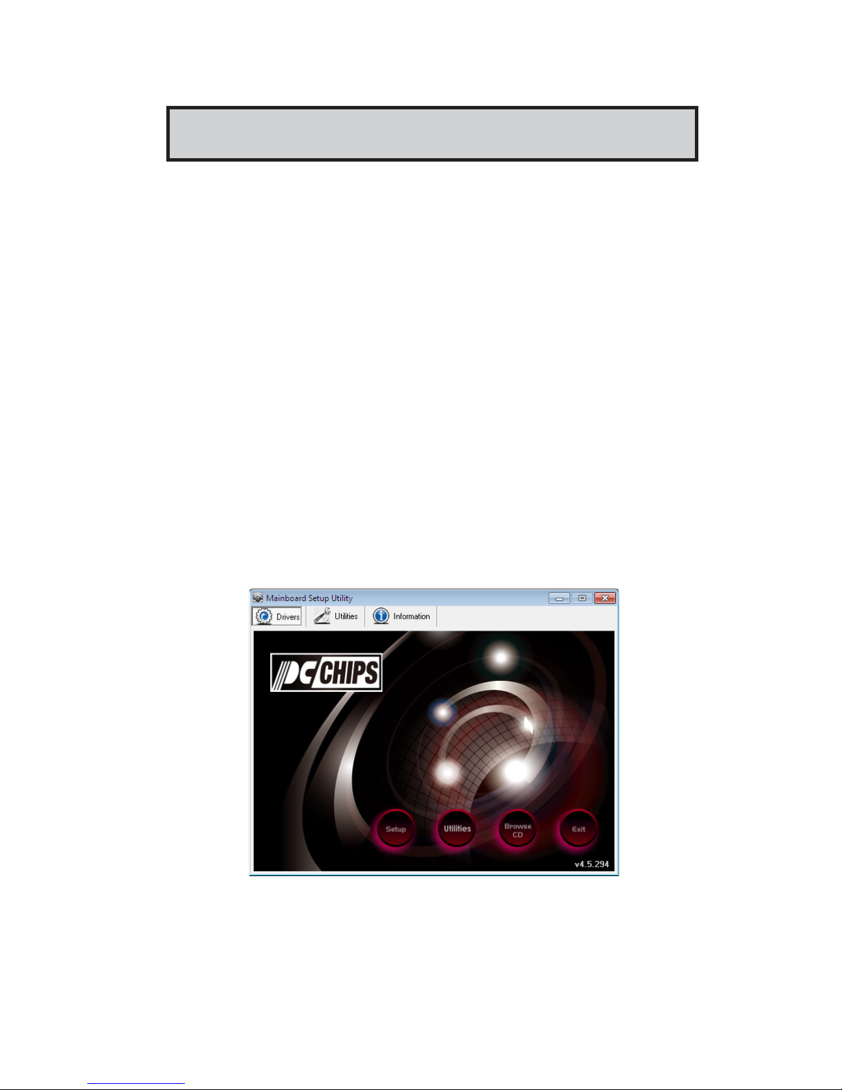
3 The screen displays four buttons of Setup, Utilities, Browse CD and
Exit on the right side, and three others Drivers, Utilities and
Information at the bottom. Please see the following illustration.
The Setup button runs the software auto-installing program as explained in next
section.
The Browse CD button is a standard Windows command that you can check the
contents of the disc with the Windows file browsing interface.
Page 45
42
Motherboard User’s Guide
The Exit button closes the Auto Setup window. To run the program again, reinsert
the DVD-ROM disk in the drive; or click the DVD-ROM driver from the Windows
Explorer, and click the Setup icon.
The Utilities button brings up a software menu. It shows the bundled software
that this mainboard supports.
The Information brings you to the Install Path where you can find out path names
of software driver.
Auto-Installing under Windows XP/Vista/7
If you are under Windows XP/7, please click the Setup button to run the software
auto-installing program while the Auto Setup screen pops out after inserting the
support DVD-ROM:
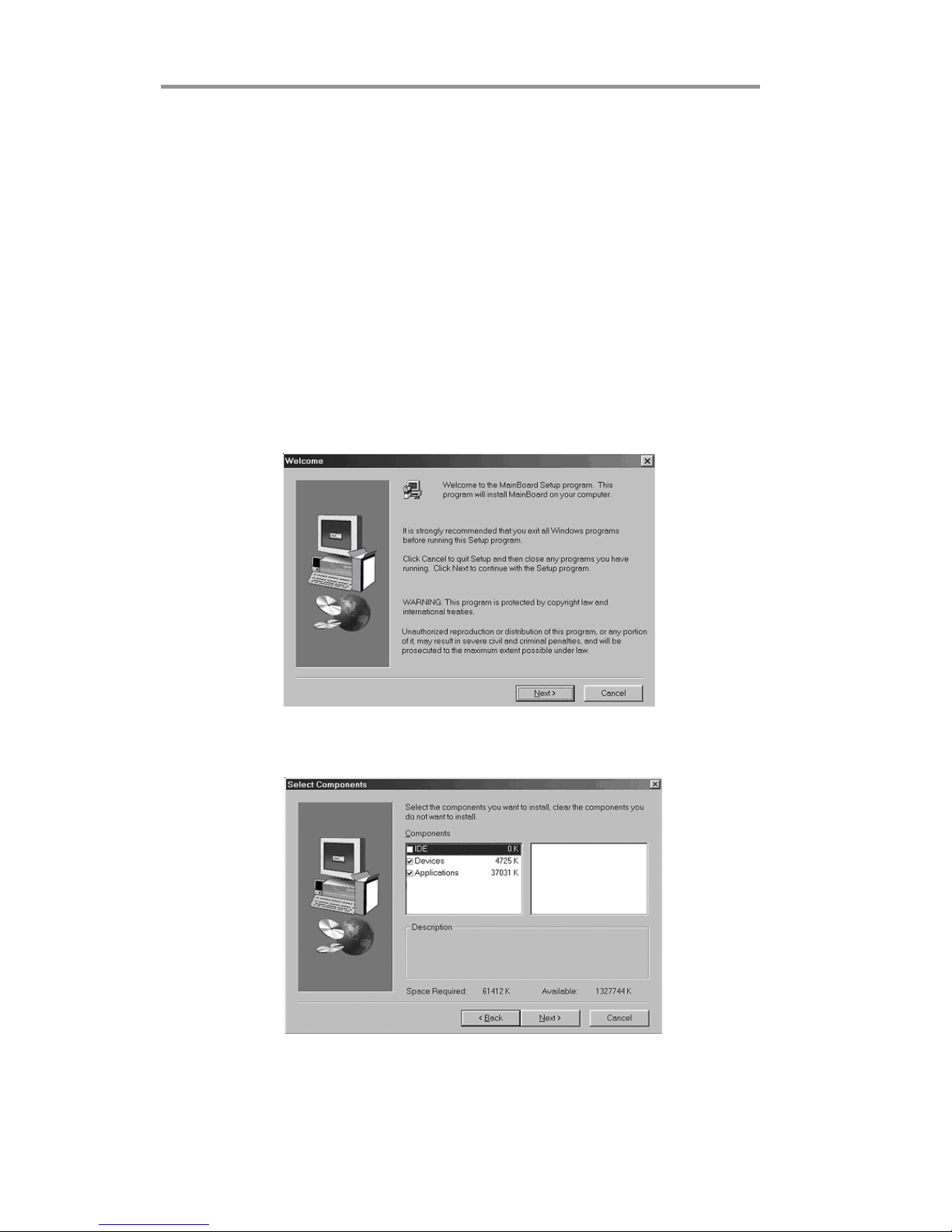
1 The installation program loads and displays the following screen. Click
the Next button.
2 Select the items that you want to setup by clicking on it (the default
options are recommended). Click the Next button to proceed.
Page 46
43
Chapter 4: Software & Applications
Bundled Software Installation
All bundled software available on the DVD-ROM is for users’ convenience. You
can install bundled software as follows:
1 Click the Utilities button while the Auto Setup screen pops out after
inserting the support DVD-ROM.
2 A software menu appears. Click the software you want to install.
3 Follow onscreen instructions to install the software program step by
step until finished.
3 The support software will automatically install.
Once any of the installation procedures start, software is automatically installed in
sequence. You need to follow the onscreen instructions, confirm commands and
allow the computer to restart as few times as needed to complete installing whatever software you selected. When the process is finished, all the support software
will be installed and start working.
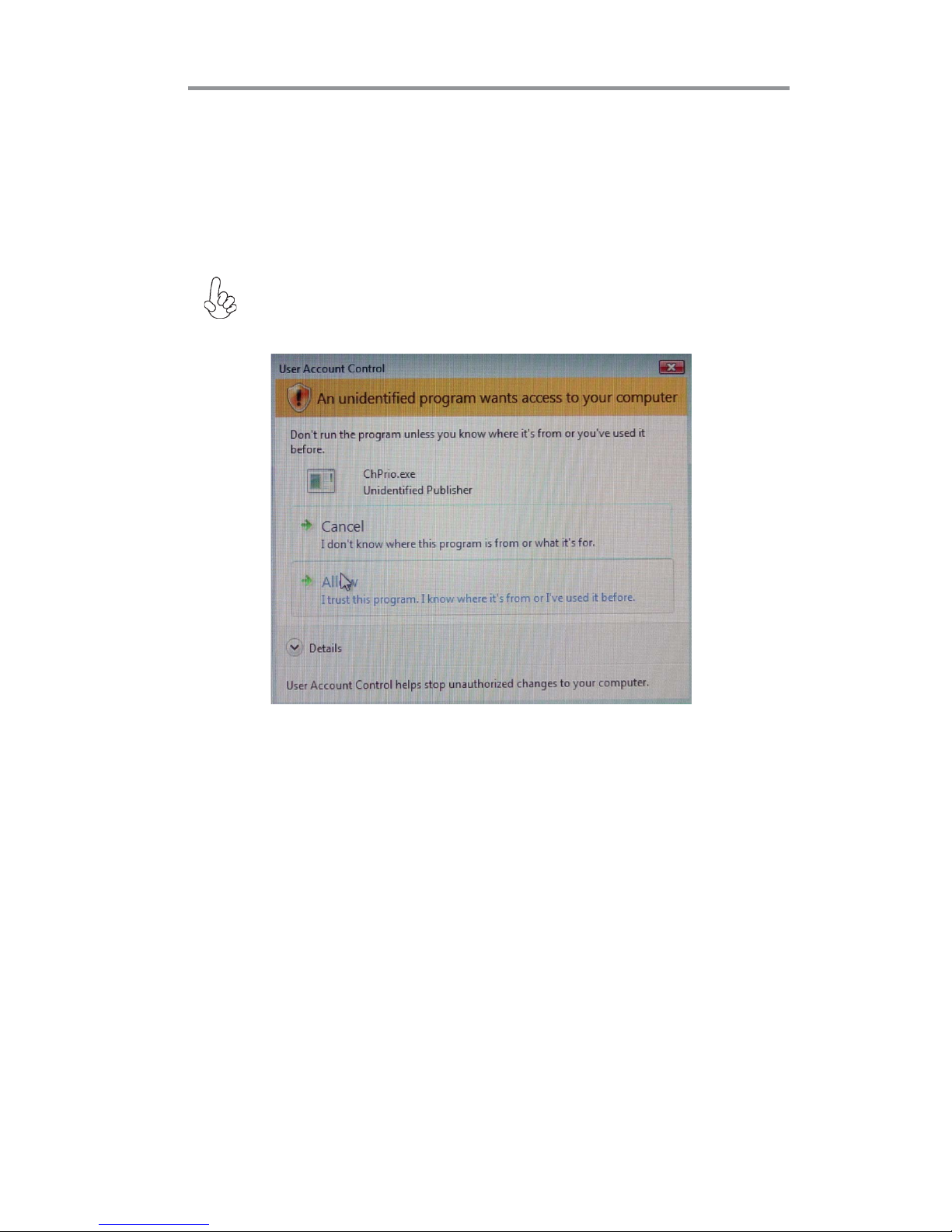
Windows Vista/7 will appear below UAC (User Account Control) message
after the system restart. You must select “Allow” to install the next driver.
Continue this process to complete the drivers installation.
Page 47
44
Motherboard User’s Guide
Chapter 5 CrossFireTMTechnology
(AMD Dual Graphics) Support
CrossFireTM Technology
The CrossFireTM technology provides significant display performance boost to
AMD-based systems by inserting the external PCI Express graphics card and
enabling both the discrete GPU and the AMD A55 graphics core to render
simultaneously in CrossFire
TM
mode.
Follow the steps below to start the CrossFire
TM
technology.
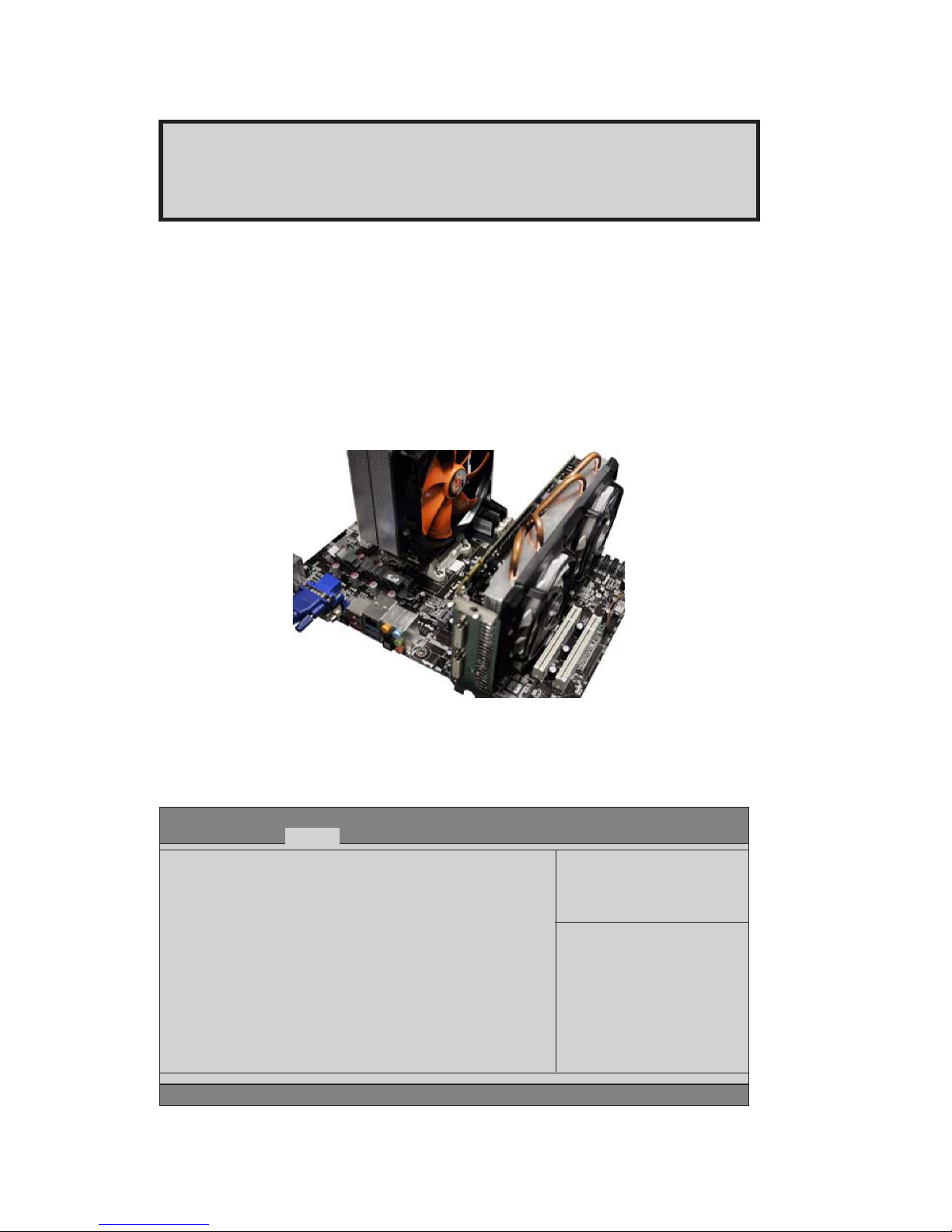
1. Insert a graphics card (which can be used for CrossFire
TM
technology, such as
HD6670 series) into the PCIEX16 slot.
Make sure that the card is properly seated on the slot.
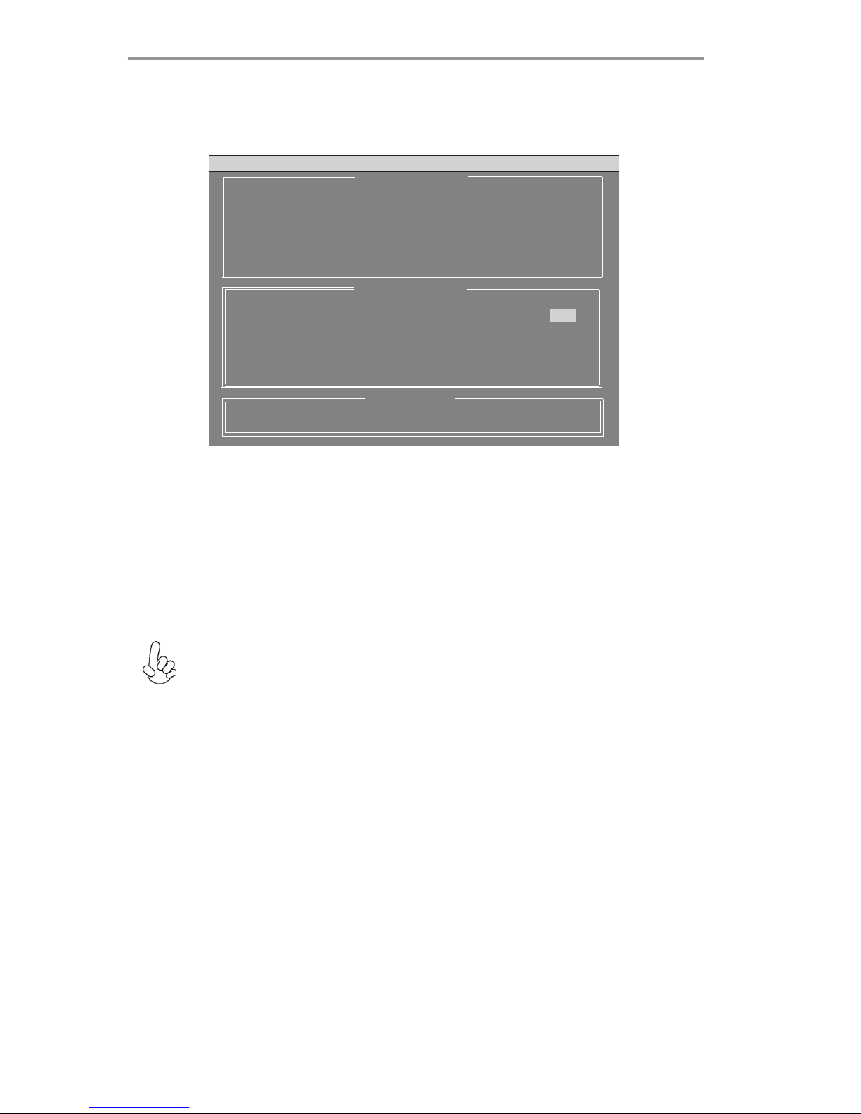
2. For CrossFire
TM
, you must enter the BIOS, set the Initate Graphic Adapter in
Advanced Menu to IGD. Then press F4 to save the configuration and exit the
BIOS.
Aptio Setup Utility - Copyright (C) 2011 American Megatrends, Inc.
Version 2.13.1216. Copyright (C) 2011 American Megatrends, Inc.
North Bridge
IGD Memory [Auto]
Initate Graphic Adapter [IGD]
CrossFire [Enabled]
IGD Share Memory Size
Main Advanced Chipset Tweak Boot Security Exit
+/- : Change Opt.
lk
mn
: Select Screen
/Click: Select Item
F1: General Help
F2: Previous Values
F3: Optimized Defaults
F4: Save & Exit
ESC/Right Click: Exit
Enter/Dbl Click : Select
*For reference only
Page 48

45
Chapter 5: CrossFireTMTechnology (AMD Dual Graphics) Support
3. Set the CrossFire in Advanced Menu to Enabled. Then press F4 to save the
configuration and exit the BIOS.
4. Click with your right mouse button on My Computer, then click the option
Manage and choose the Device Manager, finally, click the Display Adapters. The
following screen appears. Be sure that the External ATI graphics (ATI Radeon HD
6670) and Onboard graphics (Radeon HD 6530D or HD6550D) are both displaying in the Display adapters.
Aptio Setup Utility - Copyright (C) 2011 American Megatrends, Inc.
Version 2.13.1216. Copyright (C) 2011 American Megatrends, Inc.
North Chipset Configuration
IGD Memory [Auto ]
Initate Graphic Adapter [IGD]
CrossFire [Enabled]
CrossFire: Output is IGD Video
Main Advanced Chipset Tweak Boot Security Exit
+/- : Change Opt.
lk
mn
: Select Screen
/Click: Select Item
F1: General Help
F2: Previous Values
F3: Optimized Defaults
F4: Save & Exit
ESC/Right Click: Exit
Enter/Dbl Click : Select
Page 49

46
Motherboard User’s Guide
5. Enter AMD VISION Engine Control Center, you can see the option of CrossFireTM,
click it and select Enable CrossFire
TM
, then CrossFireTM starts.
To disable CrossFireTM, please make sure to cancel Enable CrossFire
TM
in Catalyst Control Center firstly.
Please reference latest AMD Dual Graphics® Technology Graphic Card
support list on AMD official website and subject to change without notice.
Page 50

47
Chapter 5: CrossFireTMTechnology (AMD Dual Graphics) Support
Recommendation
1.The APU in the A55 platform delivers a discrete-class of graphics performance
and enables leading GPU compute capability
-Adding a discrete GPU is optional to extend graphics and GPU compute capacity
2.For optimal performance uplift, AMD recommends Dual Graphics (CrossFire
TM
Technology) combinations of
-A4 and Discrete GPU model Radeon HD6450
-A6 and Discrete GPU model Radeon HD6570
-A8 and Discrete GPU model Radeon HD6570 or HD6670
3.AMD recommends a balanced system memory configuration of at least 4GB of
1333-DDR3 (2GB x 2GB).
Single channel and unbalanced memory configuration can promise both APU and
Dual Graphics performance.
4.CrossFire
TM
Technology (AMD Dual Graphics) Support on OS Windows 7 only due
to the limitation by AMD.
Page 51

48
Motherboard User’s Guide
Setting Up a bootaSetting Up a boota
Setting Up a bootaSetting Up a boota
Setting Up a boota
bb
bb
b
le RAID le RAID
le RAID le RAID
le RAID
ArAr
ArAr
Ar
rr
rr
r
aa
aa
a
yy
yy
y
This section explains how to configure a bootable AMD RAID array.
Setting Up the BIOS
Figure 1.2 SATA Configuration Screen
Chapter 6 Setting Up AMD A55 RAID Configuration
Use the arrow keys to select Advanced menu (see Figure 1.1), then select
SATA Configuration and press Enter.
2
Start your computer, then press Delete to enter the BIOS setup.
The BIOS CMOS Setup Utility screen appears.
1
Version 2.11.1210. Copyright (C) 2011, American Megatrends, Inc.
BIOS Information
System Language [English]
System Date [Sun 02/12/2012]
System Time [02:10:11]
Choose the system default
language
Aptio Setup Utility - Copyright (C) 2011 American Megatrends, Inc.
Version 2.13.1216. Copyright (C) 2011, American Megatrends, Inc.
Main Advanced Chipset Tweak Boot Security Exit
: Select Screen
+/- : Change Opt.
lk
mn
/Click: Select Item
F1: General Help
F2: Previous Values
F3: Optimized Defaults
F4: Save & Exit
ESC/Right Click: Exit
Enter/Dbl Click : Select
Aptio Setup Utility - Copyright (C) 2011 American Megatrends, Inc.
Version 2.13.1216. Copyright (C) 2011, American Megatrends, Inc.
Main Advanced Chipset Tweak Boot Security Exit
SATA Configuration
Serial-ATA Controller [Enabled]
SATA Mode [IDE Mode]
SATA Port1 WDC WD5000AAKX (500.1
SATA Port2 Not Present
SATA Port3 Not Present
SATA Port4 Not Present
: Select Screen
+/- : Change Opt.
lk
mn
/Click: Select Item
F1: General Help
F2: Previous Values
F3: Optimized Defaults
F4: Save & Exit
ESC/Right Click: Exit
Enter/Dbl Click : Select
Figure 1.1 BIOS CMOS Setup Utility Main Screen
Page 52

49
Chapter 6: Setting Up AMD A55 RAID Configuration
5
Enter the RAID BIOS Setup by pressing Ctrl-F when prompted, and proceed to
set up the AMD RAID BIOS as described in the next section.
Use the arrow keys to select the SATA Configuration (see Figure 1.2) and
globally set SATA Configuration to RAID.
3
The PC reboots.
Press F4 to save the configuration and exit.
4
Configuring the AMD RAID BIOS (Windows XP Installation)
The AMD RAID BIOS set up lets you choose the RAID type and which hard drives you
want to make part of the array.
1
Entering the RAID BIOS Setup:
Wait until you see the RAID software prompting you to press Ctrl-F.
The RAID prompt appears as part of the system POST and boot process prior
to loading of the OS. You have a few seconds to press Ctrl-F before the
screen disappears.
Press Ctrl-F.
The Main Menu screen appears (Figure 1.3).
2
Figure 1.3 Main Menu
View Drive Assignments..................[ 1 ]
Define LD..........................................[ 2 ]
Define LD..........................................[ 3 ]
Controller Configuration...................[ 4 ]
Press 1..4 to Select Option [ESC] Exit
[ Main Menu ]
[ Keys Available ]
FastBuild (tm) Utility (c) 2006 ATI Technology, Inc.
Page 53
50
Motherboard User’s Guide
Using the Define a New Array Screen
If necessary, press the tab key to move from field to field until the appropriate field is
highlighted.
Select [2], then select LD 1 in the following page.
3
The Define LD Menu screen appears (Figure 1.4).
Figure 1.4 Define LD Menu
[
mm
mm
m] Up [
nn
nn
n] Down [ESC] Exit [Space] Change Option [Ctrl-Y] Save
[ Define LD Menu ]
[ Keys Available ]
FastBuild (tm) Utility (c) 2006 ATI Technology, Inc.
LD No RAID Mode Total Drv
LD 1 RAID 0 0
Stripe Block : 64 KB Past Init : OFF
Gigabyte Boundary : ON Cache Mode : WriteThru
Channel : ID Drive Model Capacity (MB) Assignment
3 : Mas WDC WD3200AAJS-22B4 320073
N
4 : Mas WDC WD1600JS-22NVB1 160042 N
[ Drives Assignments ]
• Selecting the RAID Mode
By default, this is set to Mirroring. To change to a different RAID mode, press the
spacebar until the mode that you want appears in the RAID Mode box—RAID0/
1/10/JBOD.
Note: Not all RAID levels are supported on all platforms.
Stripe block size is given in kilobytes, and affects how data is arranged on the disk.
It is recommended to leave this value at the default Optimal, which is 64KB, but
the values can be 64 KB and 128 KB. When choose RAID 1, the Stripe block size
is unchangeable.
• Selecting the Stripe Block Size
Note: If you want to use the function of the following RAID Mode, you have to
install enough HDD.
RAID READY (1 piece of HDD); RAID 0,1 ,JBOD (2 or more pieces of HDD);
RAID 0+1 (4 pieces of HDD)
Page 54

51
Chapter 6: Setting Up AMD A55 RAID Configuration
Figure 1.5 illustrates the Define a New Array screen after two disks have been
assigned as RAID 0 array disks.
Figure 1.5 FastBuild Utility-Array Disks Assigned
Assigning the Disks
1. Select the Assignment to Y to designate a free disk to be used as a RAID array disk.
2. Press Ctrl-Y to save the configuration and exit.
The Define LD Menu screen appears (Figure 1.6).
Figure 1.6 Define LD Menu
[
mm
mm
m] Up [
nn
nn
n] Down [ESC] Exit [Space] Change Option [Ctrl-Y] Save
[ Define LD Menu ]
[ Keys Available ]
LD No RAID Mode Total Drv
LD 1 RAID 0 2
Stripe Block : 64 KB Past Init : OFF
Gigabyte Boundary : ON Cache Mode : WriteThru
Channel : ID Drive Model Capacity (MB) Assignment
3 : Mas WDC WD3200AAJS-22B4 320073 Y
4 : Mas WDC WD1600JS-22NVB1 160042
Y
[ Drives Assignments ]
FastBuild (tm) Utility (c) 2006 ATI Technology, Inc.
[
mm
mm
m] Up [
nn
nn
n] Down [ESC] Exit [Space] Change Option [Ctrl-Y] Save
[ Define LD Menu ]
[ Keys Available ]
LD No RAID Mode Total Drv Capacity(MB) Status
LD 1 RAID 0 2 318000 Functional
LD 2 ---- ---- ------ ---LD 3 ---- ---- ------ ---LD 4 ---- ---- ------ ---LD 5 ---- ---- ------ ---LD 6 ---- ---- ------ ---LD 7 ---- ---- ------ ---LD 8 ---- ---- ------ ----
FastBuild (tm) Utility (c) 2006 ATI Technology, Inc.
Page 55

52
Motherboard User’s Guide
3. Press ESC to exit.
4. Press Y to reboot.
The Main Menu screen appears (Figure 1.7).
The following screen appears (Figure 1.8).
View Drive Assignments..................[ 1 ]
Define LD..........................................[ 2 ]
Define LD..........................................[ 3 ]
Controller Configuration...................[ 4 ]
Press 1..4 to Select Option [ESC] Exit
[ Main Menu ]
[ Keys Available ]
System is going to REBOOT!
Are You Sure?
Y - Reboot / Any Key - Back
FastBuild (tm) Utility (c) 2006 ATI Technology, Inc.
RAID BIOS Version 2.5.1540.33
(c) 2006 ATI Technology, Inc. All rights reserved.
ID Mode Size TRACK-MAPPING STATUS
1 2+0 RAID 0 318000M 38661/255/63 Functional
2 ASUS DVD-E818AT
Press <Ctrl-F> to enter FastBuild (tm) Utility..._
Figure 1.8
Figure 1.7 Main Menu
Page 56

53
Chapter 6: Setting Up AMD A55 RAID Configuration
The Windows Setup program starts.
1
Copy all files in "...\RAID\ATI\A55\Floppy\Win3264" to a floppy disk.
After you complete the RAID BIOS setup, boot from the Windows CD.
Installing the RAID Drivers
Your system may come with a Windows install CD that already includes AMD RAID
drivers. If so, then this section is not relevant.
If that is not the case (or you are trying to install a new version of Windows), then you
will need an AMD RAID driver F6 install floppy. Check to see if one came with your
system. If not, you can create one by downloading the appropriate driver package and
following the steps in this section.
2
Figure 1.10 Windows Setup—Specify Devices
Press F6 and wait a few moments for the Windows Setup screen to
appear.
3
Figure 1.9
Press F6 if you need to install a third party SCSI or RAID driver...
Windows Setup
---------
S=Specify Additional Devices ENTER=Continue F3=Exit
Windows Setup
Setup could not determine the type of one or more mass storage devices.
installed in your system, or you have chosen to manually specify an adapter.
Currently, Setup will load support for the following mass storage device(s).
<none>
* To specify additional SCSI adapters, CD-ROM drivers, or special
disk controllers for use with Windows, including those for
which you have a device support disk from a mass storag device
manufacturer, press S.
* If you do not have any device support disks from a mass storage
device manufacturer, or do not want to specify additional
mass storage devices for use with Windows, press ENTER.
Page 57

54
Motherboard User’s Guide
Specify the AMD drivers.
4
a Insert the floppy that has the RAID driver, press S, then press Enter.
b Select “ATI AHCI Compatible RAID Controller-x86 platform” and press
Enter for 32-bit OS or Select “ATI AHCI Compatible RAID Controller-x64 platform” and press Enter for 64-bit OS.
The following Windows Setup screen appears listing both drivers:
Figure 1.12 Windows Setup—AMD drives listed
Figure 1.11 Windows Setup—Selected SCSI Adapter
The following Windows Setup screen appears:
ENTER=Select F3=Exit
Windows Setup
---------
You have chosen to configure a SCSI Adapter for use with windows£¬
using a device support disk provided bu an adapter manufacturer.
Select the SCSI Adapter you want from the following list, or press ESC
to return to the previous screen.
S=Specify Additional Devices ENTER=Continue F3=Exit
Windows Setup
---------
Setup will load support for the following mass storage device(s):
ATI AHCI Compatible RAID Controller-x86 platform
* To specify additional SCSI adapters, CD-ROM drivers, or special
disk controllers for use with Windows, including those for
which you have a device support disk from a mass storag device
manufacturer, press S.
* If you do not have any device support disks from a mass storage
device manufacturer, or do not want to specify additional
mass storage devices for use with Windows, press ENTER.
Page 58

55
Chapter 6: Setting Up AMD A55 RAID Configuration
Press Enter to continue with Windows XP Installation.
Be sure to leave the floppy disk inserted in the floppy drive until the blue screen
portion of Windows XP installation is completed, then take out the floppy.
Follow the instructions on how to install Windows XP.
After Windows XP is completely installed, it is recommended that you install the
ForceWare software in order to access the FastBuild RAID Management tool.
Note: Each time you add a new hard drive to a RAID array, the RAID driver will
have to be installed under Windows once for that hard drive. After that, the driver
will not have to be installed.
5
6
Page 59

Motherboard User’s Guide
56
StarStar
StarStar
Star
t up prt up pr
t up prt up pr
t up pr
obob
obob
ob
lems during assemblems during assemb
lems during assemblems during assemb
lems during assemb
ll
ll
l
yy
yy
y
After assembling the PC for the first time you may experience some start up problems.
Before calling for technical support or returning for warranty, this chapter may help to
address some of the common questions using some basic troubleshooting tips.
a) System does not power up and the fans are not running.
1.Disassemble the PC to remove the VGA adaptor card, DDR memory, LAN, USB and
other peripherals including keyboard and mouse. Leave only the motherboard, CPU with
CPU cooler and power supply connected. Turn on again to see if the CPU and power
supply fans are running.
2. Make sure to remove any unused screws or other metal objects such as screwdrivers
from the inside PC case. This is to prevent damage from short circuit.
3. Check the CPU FAN connector is connected to the motherboard.
4. For Intel platforms check the pins on the CPU socket for damage or bent. A bent pin
may cause failure to boot and sometimes permanent damage from short circuit.
5. Check the 12V power connector is connected to the motherboard.
6. Check that the 12V power & ATX connectors are fully inserted into the motherboard
connectors. Make sure the latches of the cable and connector are locked into place.
b) Power is on, fans are running but there is no display
1. Make sure the monitor is turned on and the monitor cable is properly connected to the
PC.
2. Check the VGA adapter card (if applicable) is inserted properly.
3. Listen for beep sounds. If you are using internal PC speaker make sure it is connected.
a. continuous 3 short beeps : memory not detected
b. 1 long beep and 8 short beeps : VGA not detected
Chapter 7 Trouble Shooting Tips
Page 60

Chapter 7: Trouble Shooting Tips
57
c) The PC suddenly shuts down while booting up.
1. The CPU may experience overheating so it will shutdown to protect itself. Ensure the
CPU fan is working properly.
2. From the BIOS setting, try to disable the Smartfan function to let the fan run at default
speed. Doing a Load Optimised Default will also disable the Smartfan.
Your computer, like any electrical appliance, requires proper care and maintenance. Here
are some basic PC care tips to help prolong the life of the motherboard and keep it
running as best as it can.
1. Keep your computer in a well ventilated area. Leave some space between
the PC and the wall for sufficient airflow.
StarStar
StarStar
Star
t up prt up pr
t up prt up pr
t up pr
obob
obob
ob
lems after prlems after pr
lems after prlems after pr
lems after pr
olong useolong use
olong useolong use
olong use
After a prolong period of use your PC may experience start up problems again. This may
be caused by breakdown of devices connected to the motherboard such as HDD, CPU fan,
etc. The following tips may help to revive the PC or identify the cause of failure.
1. Clear the CMOS values using the CLR_CMOS jumper. Refer to CLR_CMOS jumper in
Chapter 2 for Checking Jumper Settings in this user manual. When completed, follow up
with a Load Optimised Default in the BIOS setup.
2. Check the CPU cooler fan for dust. Long term accumulation of dust will reduce its
effectiveness to cool the processor. Clean the cooler or replace a new one if necessary.
3. Check that the 12V power & ATX connectors are fully inserted into the motherboard
connectors. Make sure the latches of the cable and connector are locked into place.
4. Remove the hard drive, optical drive or DDR memory to determine which of these
component may be at fault.
Maintenance and care tipsMaintenance and care tips
Maintenance and care tipsMaintenance and care tips
Maintenance and care tips
2. Keep your computer in a cool dry place. Avoid dusty areas, direct sunlight
and areas of high moisture content.
3. Routinely clean the CPU cooler fan to remove dust and hair.
4. In places of hot and humid weather you should turn on your computer once
every other week to circulate the air and prevent damage from humidity.
5. Add more memory to your computer if possible. This not only speeds up the
system but also reduces the loading of your hard drive to prolong its life span.
6. If possible, ensure the power cord has an earth ground pin directly from the
wall outlet. This will reduce voltage fluctuation that may damage sensitive devices.
Page 61
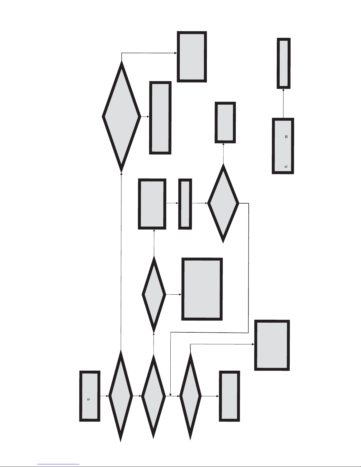
Power Bu
on is pressed
but PC fails to start.
Yes
Check if Power Supply
Unit
(PSU) is working
No
No
Any Beep soundΛ
No
CLR CMOS and check
if CPU 12V power
is connected
art the PC stRe
Problem with PSU or board?
If board problem -> contact RMA
AC power cord is plu ed gg
and PSU switch is turned on?
Yes
oblem rBoard p
-> contact RMA
No
- If 3 short beeps:
DIMM memory not properly
inserted or memory failure
- If 1 long beep and 8 short beeps:
VGA not detected
Yes
Yes
Halt at POST screenΛ
Yes
R CMOLC S and restart.
If fail, contact RMA
Yes
No
Peripheral device issue
- HDD problem.
- CMOS setup error,
dnee to CLRCMOS.
System fail to start or unstable
a
er modify BIOS se
ng.
MCLR C OS and restart
Turn on PSU switch
or connect to wall socket
start. eand r
No
Check if monitor h sa
dis
play
Check if monitor
has display
Basic Troubleshooting Flowchart
 Loading...