

Page 1

Page 2

Page 3

Preface
Copyright
This publication, including all photographs, illustrations and software, is protected under
international copyright laws, with all rights reserved. Neither this manual, nor any of the
material contained herein, may be reproduced without written consent of the author.
Version 1.2a
Disclaimer
The information in this document is subject to change without notice. The manufacturer
makes no representations or warranties with respect to the contents hereof and specifically
disclaims any implied warranties of merchantability or fitness for any particular purpose.
The manufacturer reserves the right to revise this publication and to make changes from
time to time in the content hereof without obligation of the manufacturer to notify any
person of such revision or changes.
Trademark Recognition
Microsoft, MS-DOS and Windows are registered trademarks of Microsoft Corp.
MMX, Pentium, Pentium-II, Pentium-III, Celeron are registered trademarks of Intel Cor-
poration.
Other product names used in this manual are the properties of their respective owners and
are acknowledged.
Federal Communications Commission (FCC)
This equipment has been tested and found to comply with the limits for a Class B digital
device, pursuant to Part 15 of the FCC Rules. These limits are designed to provide reasonable protection against harmful interference in a residential installation. This equipment
generates, uses, and can radiate radio frequency energy and, if not installed and used in
accordance with the instructions, may cause harmful interference to radio communications.
However, there is no guarantee that interference will not occur in a particular installation.
If this equipment does cause harmful interference to radio or television reception, which
can be determined by turning the equipment off and on, the user is encouraged to try to
correct the interference by one or more of the following measures:
• Reorient or relocate the receiving antenna
• Increase the separation between the equipment and the receiver
• Connect the equipment onto an outlet on a circuit different from that to which
the receiver is connected
• Consult the dealer or an experienced radio/TV technician for help
Shielded interconnect cables and a shielded AC power cable must be employed with this
equipment to ensure compliance with the pertinent RF emission limits governing this
device. Changes or modifications not expressly approved by the system’s manufacturer
could void the user’s authority to operate the equipment.
Preface
Page 4

ii
Declaration of Conformity
This device complies with part 15 of the FCC rules. Operation is subject to the following
conditions:
• This device may not cause harmful interference, and
• This device must accept any interference received, including interference
that may cause undesired operation
Canadian Department of Communications
This class B digital apparatus meets all requirements of the Canadian Interference-causing
Equipment Regulations.
Cet appareil numérique de la classe B respecte toutes les exigences du Réglement sur le
matériel brouilieur du Canada.
About the Manual
The manual consists of the following:
Chapter 1
Introducing the Motherboard
Describes features of the motherboard.
Go to
H
page 1
Chapter 2
Installing the Motherboard
Chapter 3
Using BIOS
Chapter 4
Using the Motherboard Software
Describes installation of motherboard
components.
Go to
Provides information on using the BIOS
Setup Utility.
Go to
Describes the motherboard software
Go to
H
H
H
page 7
page 27
page 39
Preface
Page 5

TT
ABLE OF CONTENTSABLE OF CONTENTS
T
ABLE OF CONTENTS
TT
ABLE OF CONTENTSABLE OF CONTENTS
Preface i
iii
Chapter 1
Introducing the Motherboard 1
Introduction.................................................................................................1
Feature..........................................................................................................2
Motherboard Components........................................................................4
1
Chapter 2
Installing the Motherboard 7
Safety Precautions......................................................................................7
Choosing a Computer Case.......................................................................7
Installing the Motherboard in a Case......................................................7
Checking Jumper Settings.........................................................................8
Setting Jumpers..............................................................................8
Checking Jumper Settings..............................................................9
Jumper Settings..............................................................................9
Connecting Case Components...............................................................10
Front Panel Connector.................................................................12
Installing Hardware...................................................................................13
Installing the Processor...............................................................13
Installing Memory Modules.........................................................15
Installing a Hard Disk Drive/CD-ROM/SATA Hard Drive........16
Installing a Floppy Diskette Drive...............................................18
Installing Add-on Cards..............................................................19
Connecting Optional Devices......................................................20
Connecting I/O Devices..........................................................................23
7 7
7
7 7
Chapter 3
Using BIOS 27
About the Setup Utility............................................................................27
The Standard Configuration........................................................27
Entering the Setup Utility..............................................................27
Updating the BIOS.......................................................................29
Using BIOS................................................................................................29
Standard CMOS Features...........................................................30
Advanced Setup............................................................................31
Features.......................................................................................33
27 27
27
27 27
Page 6

iv
Power Management Setup...........................................................34
PCI/Plug and Play Setup.............................................................35
BIOS Security Features................................................................36
CPU PnP Setup............................................................................37
Hardware Monitor.......................................................................38
Load Best Performance Settings..................................................39
Load Optimal Defaults................................................................39
Save Changes and Exit................................................................39
Discard Changes and Exit...........................................................39
Chapter 4
39 39
39
39 39
Using the Motherboard Software 39
About the Software CD-ROM................................................................39
Auto-installing under Windows 98/ME/2000/XP................................39
Running Setup..............................................................................40
Manual Installation..................................................................................42
Utility Software Reference.......................................................................42
Multi-Language Translation
Page 7

Chapter 1
Introducing the Motherboard
Introduction
Thank you for choosing the 915P-A motherboard. This motherboard is a high performance, enhanced function motherboard that supports LGA775 Pentium 4 processors for
high-end business or personal desktop markets.
The motherboard incorporates the 915-P Northbridge (NB) and ICH6 Southbridge (SB)
chipsets. The Northbridge supports a Front Side Bus (FSB) frequency of 800/533 MHz using
a scalable FSB Vcc_CPU. The momory controller supports DDR memory DIMM frequencies of 333MHz and 400 MHz or DDR2 memory DIMM frequencies of 400 MHz and 533
MHz. It supports four DDR Sockets with up to maximum memory of 2 GB. DDR Maximum
memory bandwidth of 3.2 GB/s in single-channel is supported, or 8.5 GB/s in dual-channel
interleaved mode assuming DDR2 533MHz. Aside from the onboard AGP Express, one 16lane PCI Express slot, intended for Graphics Interface, is fully compliant to the PCI
Express Base Specification revision 1.0a.
The ICH6 Southbridge supports two PCI slots which are PCI 2.3 compliant. In addition, two
PCI Express x1 slots are supported, fully compliant to the PCI Express Base Specification,
Revision 1.0a. It implements an EHCI compliant interface that provides 480Mb/s bandwidth for eight USB 2.0 ports, integrates Azalia codec supporting Azilia standard that
features a 8-channels High Definition Audio output. One onboard IDE connector supports
2 IDE devices in ATA-100/66 mode. The Southbridge integrates a Serial ATA host controller
that is SATA v1.0 compliant, supporting four SATA ports with maximum transfer rate up to
150 MB/s each.
The 915P-A motherboard is equipped with advanced full set of I/O ports in the rear panel,
including PS/2 mouse and keyboard connectors, COM1, LPT1, four USB ports, one optional LAN port, and audio jacks for microphone, line-in and 8-ch line out.
1
Introducing the Motherboard
Page 8

2
Feature
Processor
Processor
The 915P-A uses an LGA775 type of Pentium 4 that carries the following features:
• Accommodates Intel P4 Prescott processors
• Supports a system bus (FSB) of 800/533MHz
• Supports “Hyper-Threading” technology CPU
“Hyper-Threading” technology enables the operating system into thinking it’s hooked
up to two processors, allowing two threads to be run in parallel, both on separate
“logical” processors within the same physical processor.
Chipset
Chipset
The 915-P Northbridge (NB) and ICH6 Southbridge (SB) chipset is based on an innovative and scalable architecture with proven reliability and performance.
915P (NB)
• Supports 32-bit host bus addressing, allowing the CPU to
access the entire 4 GB of the memory address space.
• Has a 12-deep In-Order Queue to support up to twelve
outstanding piplined address requests on the host bus.
• Supports one PCI Express x16 for Graphics Interface, fully
compliant to the PCI Express Base Specification revision
1.0a.
• Supports 256-Mb, 512-Mb and 1-Gb DDR technologies for
x8 and x16 devices
• Supports up to four unbuffered DIMM
915P chipset can only support 256-Mb, 512-Mb and 1-Gb DDR
technologies for x8 and x16 device, NOT support 128-Mb DDR
technology. That is, 256 MB Double Side Memory Module &
128 MB Single Side Memory Module are NOT support.
ICH6 (SB) • Enhanced DMA Controller , interrupt controller, and timer func-
Memory
Memory
• Supports DDR 400/333 MHz or DDR2 533/400 DDR SDRAM DIMMs
• Accommodates four unbuffered DIMMs
• Up to 1 GB per DIMM with maximum memory size up to 2 GB
Users please note that DDR & DDR2 can’t both be applied at the same time on
this motherboard. Users can use either DDR or DDR2 memory modules only!
tions
• Compliant with PCI Express Base Specification, Revision
1.0a
• Compliant with PCI 2.3 specificaiton
• Compliant with Serial ATA 1.0a specification
• Integrated USB 2.0 Host Controller supporting up to eight
USB 2.0 ports
• Integrated LAN controller
• Compliant with Azalia specification supporting 8 Channels
of audio outputs
• Integrated IDE controller supports Ultra ATA100/66/33
Introducing the Motherboard
Page 9

Audio
Audio
• Compliant with Azalia specification, supporting 8 channel DACs with SNR >
95dB
• Compabilities: 192/96/48/44.1 KHz with 24/20/16 bits
• 8 Smart Jack I/O port support
• Extensive jack detection via RNM (resistors network method) that can be
used to monitor the plugging status of each jack
• Digital S/PDIF OUT & IN support
Expansion Options
Expansion Options
The motherboard comes with the following expansion options:
• One AGP Express slot
• One PCI Express x16 for Graphic Interface
• Two PCI Express x1
• Two 32-bit PCI v2.3 compliant slots
• One 40-pin IDE low profile header that support two IDE devices
• One floppy disk drive interface
• Four 7-pin SATA connector
The 915P-A motherboard supports UltraDMA bus mastering with transfer rates of 100/
66 MB/s.
Onboard LAN (Optional)
Onboard LAN (Optional)
The onboard LAN controller provides the following features:
• Support 10/100/1000 Mbps speed operation(10/100 Mbps optional)
• Supports PCI v2.3, 32-bit, 33/66-MHz
• Supports fully with IEEE 802.3z
3
Integrated I/O
Integrated I/O
The motherboard has a full set of I/O ports and connectors:
• Two PS/2 ports for mouse and keyboard
• One serial port
• One parallel port
• One LAN port (optional)
• Audio jacks for microphone in, line-in and 8-ch High Definition Audio output
BIOS Firmware
BIOS Firmware
This motherboard uses AMI BIOS that enables users to configure many system
features including the following:
• Power management
• Wake-up alarms
• CPU parameters
• CPU and memroy timing
The firmware can also be used to set parameters for different processor clock speeds.
Some hardware specifications and software items are subject to change
with out prior notice.
Introducing the Motherboard
Page 10
4
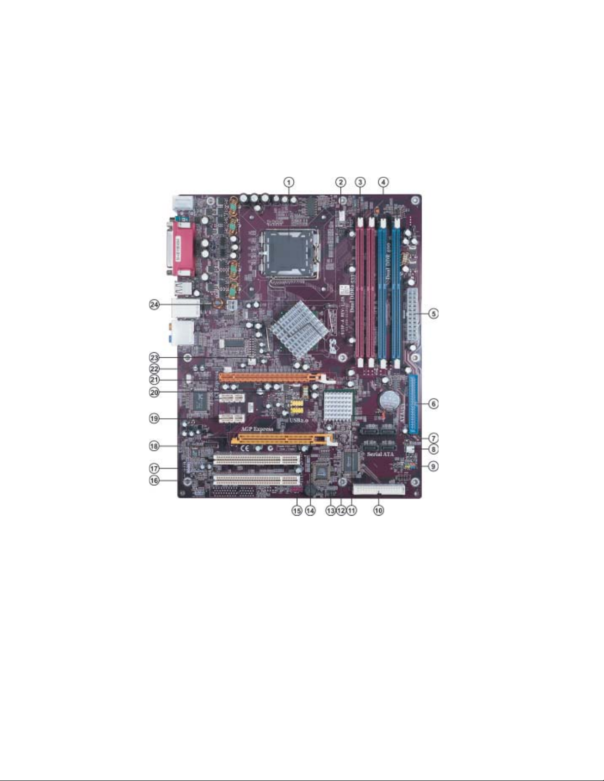
Motherboard Components
Introducing the Motherboard
Page 11

Table of Motherboard Components
LABEL COMPONENT
1 CPU Socket LGA775 socket for Pentium 4 CPUs
2 CPU_FAN1 CPU cooling fan connector
3 DIMM1~2 240-pin DDR2 SDRAM slots
4 DIMM3~4 184-pin DDR SDRAM slots
5 PWR1 Standard 24-pin ATX power connector
6 IDE1 Primary IDE channel
7 SATA1~4 Serial ATA connectors
8 CHS_FAN1 Chasis cooling fan connector
9 PANEL1 Panel connector for case switches and LEDs
10 FDC1 Floppy diskette drive connector
11 JP1 Clear CMOS jumper
12 JP11 BIOS protect jumper
13 IR1 Internal infrared header
14 AGP-E1 AGP Express slot
15 AUDIO2 Front panel audio header
16 PCI1~2 32-bit add-on card slots
17 SPDIF-O-1 SPDIF out header
18 CD1 CD-in connector
19 PCI-E2~3 PCI Express x1 slots
20 USB3-4 Front Panel USB headers
21 PCI-E1 PCI Express x16 graphics card slot
22 AUX_FAN1 Auxliary cooling fan connector
23 NB_FAN1 Northbridge cooling fan connector
24 PWR2 Auxiliary 4-pin power connector
5
*Stands for optional components
Users please note that DDR & DDR2 can’t both be applied at the same time on
this motherboard. Users can use either DDR or DDR2 memory modules only!
This concludes Chapter 1. The next chapter explains how to install the motherboard.
Introducing the Motherboard
Page 12

6
Memo
Introducing the Motherboard
Page 13

Chapter 2
Installing the Motherboard
Safety Precautions
• Follow these safety precautions when installing the motherboard
• Wear a grounding strap attached to a grounded device to avoid damage from
static electricity
• Discharge static electricity by touching the metal case of a safely grounded
object before working on the motherboard
• Leave components in the static-proof bags they came in
• Hold all circuit boards by the edges. Do not bend circuit boards
Choosing a Computer Case
There are many types of computer cases on the market. The motherboard complies with
the specifications for the ATX system case. First, some features on the motherboard are
implemented by cabling connectors on the motherboard to indicators and switches on the
system case. Make sure that your case supports all the features required. Secondly, 915PA supports one or two floppy diskette drives and two enhanced IDE drives. Make sure that
your case has sufficient power and space for all drives that you intend to install.
Most cases have a choice of I/O templates in the rear panel. Make sure that the I/O
template in the case matches the I/O ports installed on the rear edge of the motherboard.
This motherboard carries a ATX form factor of 305 x 244 mm. Choose a case that
accommodates this form factor.
7
Installing the Motherboard in a Case
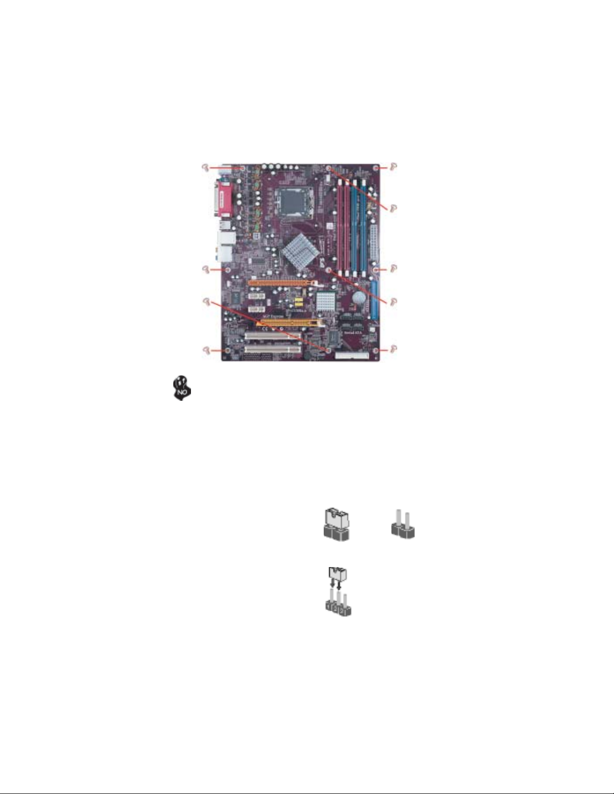
Refer to the following illustration and instructions for installing the motherboard in a case.
Most system cases have mounting brackets installed in the case, which correspond the holes
in the motherboard. Place the motherboard over the mounting brackets and secure the
motherboard onto the mounting brackets with screws.
Ensure that your case has an I/O template that supports the I/O ports and expansion slots
on your motherboard.
Installing the Motherboard
Page 14
8
Do not over-tighten the screws as this can stress the motherboard.
Checking Jumper Settings
This section explains how to set jumpers for correct configuration of the motherboard.
Setting Jumpers
Use the motherboard jumpers to set system configuration options. Jumpers with more than
one pin are numbered. When setting the jumpers, ensure that the jumper caps are placed on
the correct pins.
The illustrations show a 2-pin jumper. When
the jumper cap is placed on both pins, the
jumper is SHORT. If you remove the jumper
cap, or place the jumper cap on just one pin,
the jumper is OPEN.
This illustration shows a 3-pin jumper. Pins
1 and 2 are SHORT
SHORT OPEN
Installing the Motherboard
Page 15
Checking Jumper Settings
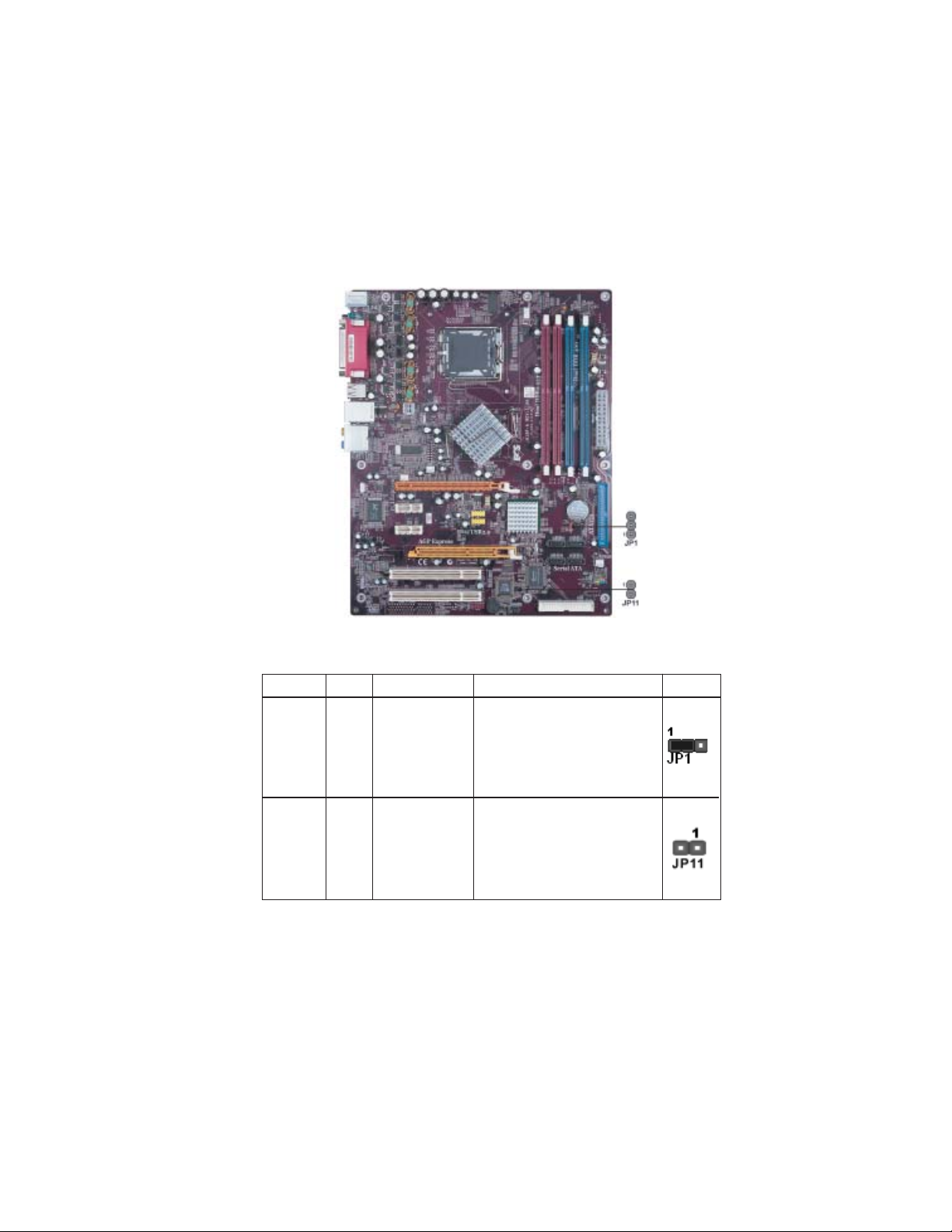
The following illustration shows the location of the motherboard jumpers. Pin 1 is labeled.
9
Jumper Settings
Jumper
JP1
JP11
Type
3-pin
2-pin
Description
CLEAR CMOS
BIOS WRITE
Setting (default)
1-2: NORMAL
2-3: CMOS CLEAR
Before clearing the
CMOS, make sure to
turn off the system.
OPEN: WRITW UNPROTECT
SHORT: WRITE PROTECT
Installing the Motherboard
Page 16
10
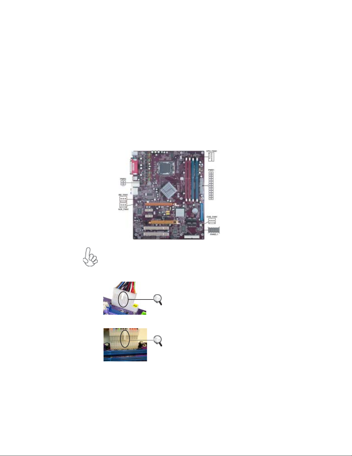
Connecting Case Components
After you have installed the motherboard into a case, you can begin connecting the motherboard components. Refer to the following:
1 Connect the CPU cooling fan cable to CPU_FAN1.
2 Connect the case cooling fan connector to CHS_FAN1.
3 Connect the Northbridge cooling fan connector to NB_FAN1.
3 Connect the power fan connector to AUX_FAN1.
4 Connect the case switches and indicator LEDs to the PANEL1.
6 Connect the standard power supply connector to PWR1.
7 Connect the auxiliary case power supply connector to PWR2.
Connecting 20/24-pin power cable
Users please note that the 20-pin and 24-pin power cables can both be connected to the ATX1 connector. With the 20-pin power cable, just align the 20pin power cable with the pin 1 of the ATX1 connector. However, using 20-pin
power cable may cause the system to become unbootable or unstable because of
insufficient electricity.
Users please note that when installing 20pin power cable, the latche of power cable
falls on the left side of the ATX1 connector
20-pin power cable
24-pin power cable
latch, just as the picture shows.
Users please note that when installing 24pin power cable, the latches of power cable
and the ATX1 match perfectly.
Installing the Motherboard
Page 17
CPUFAN1: F AN Power Connectors
Pin Signal Name Function
1 GND System Ground
2
+12V Power +12V
3 Sense Sensor
4 PWM CPU FAN control
CHS_FAN1/NB_F AN1/AUX_FAN1: F AN Power Connectors
Pin Signal Name Function
1 GND System Ground
2 +12V Power +12V
3 Sense Sensor
PWR2: ATX 12V Power Connector
Pin Signal Name
1 Ground
2 Ground
3 +12V
4 +12V
PWR1: A TX 24-pin Power Connector
Pin Signal Name Pin Signal Name
1 +3.3V 13 +3.3V
2 +3.3V 14 -12V
3 Ground 15 COM
4 +5V 16 PS_ON
5 Ground 17 COM
6 +5V 18 COM
7 Ground 19 COM
8 PWRGD 20 -5V
9 +5VSB 21 +5V
10 +12V 22 +5V
11 +12V 23 +5V
12 +3.3V 24 COM
11
Installing the Motherboard
Page 18
12
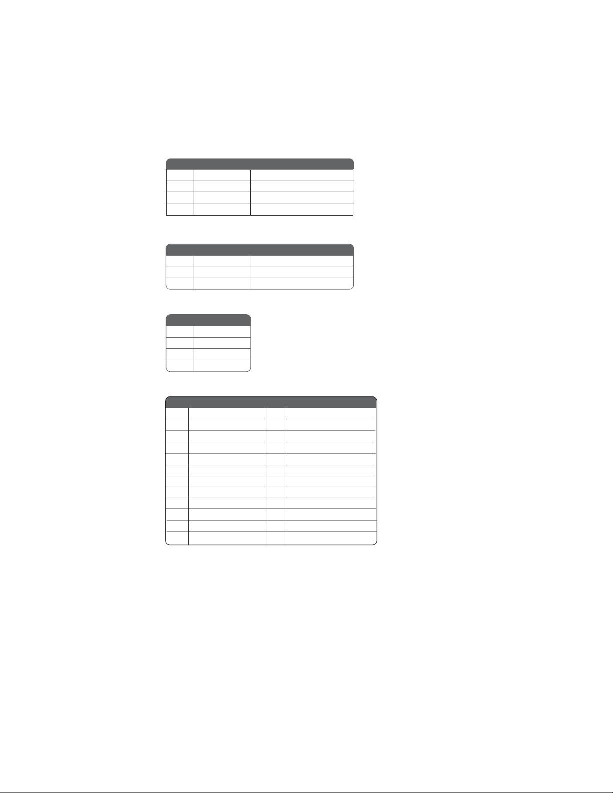
Front Panel Connector
The front panel connector (PANEL1) provides a standard set of switch and LED connectors commonly found on ATX or micro-ATX cases. Refer to the table below for information:
Pin Signal Function Pin Signal Function
1 HD_LED_P Hard disk LED+ 2 FP PWR/SLP *MSG LED+
3 HD_LED_N Hard disk LED-
5 RST_SW_N Reset Switch
7 RST_SW_P Reset Switch
9 RSVD Reserved
* MSG LED (dual color or single color)
Hard Drive Activity LED
Connecting pins 1 and 3 to a front panel mounted LED provides visual indication that data
is being read from or written to the hard drive. For the LED to function properly, an IDE
drive should be connected to the onboard IDE interface. The LED will also show activity
for devices connected to the SCSI (hard drive activity LED) connector.
4 FP PWR/SLP *MSG LED-
6 PWR_SW_P Power Switch
8 PWR_SW_N Power Switch
10 Key No pin
Power/Sleep/Message waiting LED
Connecting pins 2 and 4 to a single or dual-color, front panel mounted LED provides power
on/off, sleep, and message waiting indication.
Reset Switch
Supporting the reset function requires connecting pin 5 and 7 to a momentary-contact
switch that is normally open. When the switch is closed, the board resets and runs POST.
Power Switch
Supporting the power on/off function requires connecting pins 6 and 8 to a momentarycontact switch that is normally open. The switch should maintain contact for at least 50 ms
to signal the power supply to switch on or off. The time requirement is due to internal debounce circuitry. After receiving a power on/off signal, at least two seconds elapses before
the power supply recognizes another on/off signal.
Installing the Motherboard
Page 19

Installing Hardware
Installing the Processor
Caution: When installing a CPU heatsink and cooling fan make sure that
you DO NOT scratch the motherboard or any of the surface-mount
resistors with the clip of the cooling fan. If the clip of the cooling fan
scrapes across the motherboard, you may cause serious damage to the
motherboard or its components.
On most motherboards, there are small surface-mount resistors near the
processor socket, which may be damaged if the cooling fan is carelessly
installed.
Avoid using cooling fans with sharp edges on the fan casing and the clips.
Also, install the cooling fan in a well-lit work area so that you can clearly
see the motherboard and processor socket.
Before installing the Processor
This motherboard automatically determines the CPU clock frequency and system bus
frequency for the processor. You may be able to change these settings by making changes
to jumpers on the motherboard, or changing the settings in the system Setup Utility. We
strongly recommend that you do not over-clock processors or other components to run
faster than their rated speed.
Warning: Over-clocking components can adversely affect the reliability
of the system and introduce errors into your system. Over-clocking can
permanently damage the motherboard by generating excess heat in
components that are run beyond the rated limits.
13
This motherboard has a LGA 775 socket. When choosing a processor, consider the performance requirements of the system. Performance is based on the processor design, the clock
speed and system bus frequency of the processor, and the quantity of internal cache memory
and external cache memory.
Installing the Motherboard
Page 20
14
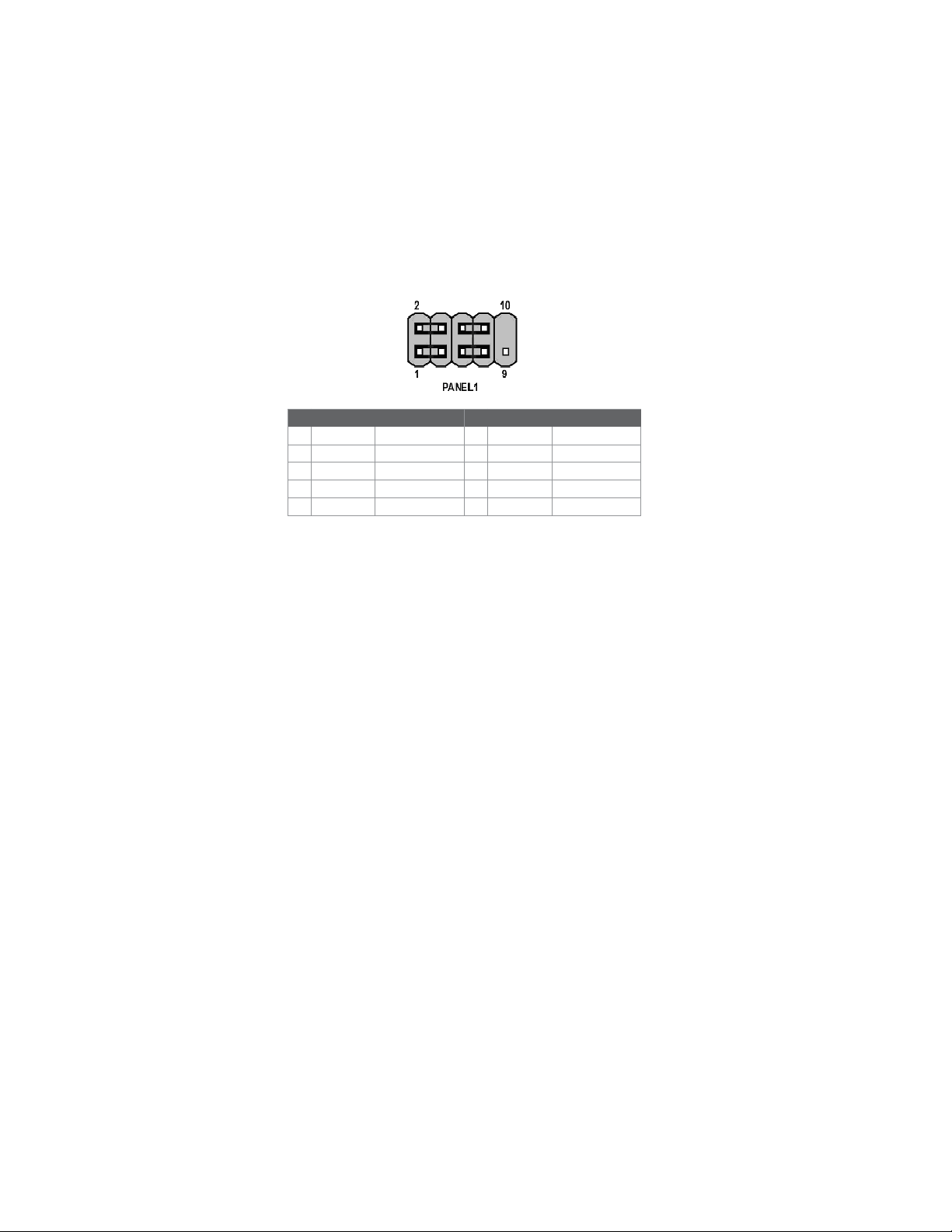
CPU Installation Procedure
The following illustration shows CPU installation components.
A. Unload the cap
· Use thumb & forefinger to hold the
lifting tab of the cap.
· Lift the cap up and remove the cap
completely from the socket.
B. Open the load plate
· Use thumb & forefinger to hold the
hook of the lever, pushing down and pulling
aside unlock it.
· Lift up the lever.
· Use thumb to open the load plate. Be
careful not to touch the contacts.
C. Install the CPU on the socket
· Orientate CPU package to the socket.
Make sure you match triangle marker
to pin 1 location.
D. Close the load plate
· Slightly push down the load plate onto the
tongue side, and hook the lever.
· CPU is locked completely.
E. Apply thermal grease on top of the CPU.
F. Fasten the cooling fan supporting base onto
the CPU socket on the motherboard.
G. Make sure the CPU fan is plugged to the
CPU fan connector. Please refer to the CPU
cooling fan user’s manual for more detail
installation procedure.
To achieve better airflow rates and heat dissipation, we suggest that you use
a high quality fan with 3800 rpm at least. CPU fan and heatsink installation procedures may vary with the type of CPU fan/heatsink supplied. The
form and size of fan/heatsink may also vary.
Installing the Motherboard
Page 21

Installing Memory Modules
This motherboard accomodates four memory modules. It can support two 184-pin 2.5V
unbuffered DIMM, DDR 400/333 or two 240-pin 1.8V DDR2 533/400. The total memory
capacity is 2GB.
Users please note that DDR & DDR2 can’t both be applied at the same time on
this motherboard. Users can use either DDR or DDR2 memory modules only!
DDR SDRAM memory module table
Memory module Memory Bus
DDR 333 166MHz
DDR 400 200MHz
DDR2 SDRAM memory module table
Memory module Memory Bus
DDR2 400 200MHz
DDR2 533 266MHz
You must install at least one module in any of the four slots. Each module can be installed
with 256 MB to 1 GB of memory; total memory capacity is 2 GB.
Do not remove any memory module from its antistatic packaging until you
are ready to install it on the motherboard. Handle the modules only by
their edges. Do not touch the components or metal parts. Always wear a
grounding strap when you handle the modules.
15
Installation Procedure
Refer to the following to install the memory modules.
1 This motherboard supports unbuffered DDR and DDR2 SDRAM .
2 Push the latches on each side of the DIMM slot down.
3 Align the memory module with the slot. The DIMM slots are keyed with
notches and the DIMMs are keyed with cutouts so that they can only be
installed correctly.
4 Check that the cutouts on the DIMM module edge connector match the notches
in the DIMM slot.
5 Install the DIMM module into the slot and press it firmly down until it seats
correctly. The slot latches are levered upwards and latch on to the edges of
the DIMM.
6 Install any remaining DIMM modules.
Installing the Motherboard
Page 22

16
Table A: DDR QVL (Qualified Vender List)
The following DDR memory modules have been tested and qualified
for use with this motherboard.
Type Size Brand Chip
256MB A-DATA ADD8608A8A-5B
256MB Hynix HY5DU56822BT-D43
256MB KingMax KDL684T4AA-50
256MB Kingston 9905192-012.A01
256MB SAMSUNG K4H560838D-TCC4
DDR 400
DDR 433 512MB Corsair CMX512-3500C2PT
DDR 450 256MB A-DATA ADD8608A8A-4.5B
DDR 550 512MB Corsair CMX512-4400PT
256MB TwinMOS TMD7608F8E50D
512MB CORSAIR CMX512-3200C2PT
512MB Infineon HYB25D256800BT-5
512MB Kingston D3208DL1T-5
512MB KingMax KDL388P4EA-50A
512MB ValueSelect VS32MB-5 2B0402
1GB Corsair CMX1024-3200PT
Table B: DDR2 QVL (Qualified Vender List)
The following DDR2 memory modules have been tested and qualified
for use with this motherboard.
Type Size Brand Chip
256M SAMSUNG K4T56083QF-GCCC DDR2 400
512M SAMSUNG K4T51083QB-GCCC
DDR2 533
256M Corsair CM2X256A-4200
256M Kingston KVR533D2N4
256M SAMSUNG K4T56083QF-GCD5
512M G.SKILL G76 GT
512M SAMSUNG K4T51083QB-GCD5
256M ELPIDA E2508AA-DF-E DDR2 700
512M ELPIDA E2508AA-DF-E
Installing the Motherboard
Page 23

Installing a Hard Dish Drive/CD-ROM/SA T A Hard Drive
This section describes how to install IDE devices such as a hard disk drive and a CD-ROM
drive.
About IDE Devices
Your motherboard has one IDE channel interface. An IDE ribbon cable supporting two IDE
devices is bundled with the motherboard.
You must orient the cable connector so that the pin1 (color) edge of the
cable correspoinds to the pin 1 of the I/O port connector.
IDE1: IDE Connector
This motherboard supports four high data transfer SATA ports with each runs up to 150
MB/s. To get better system performance, we recommend users connect the CD-ROM to
the IDE channel, and set up the hard dives on the SATA ports.
17
IDE devices enclose jumpers or switches used to set the IDE device as MASTER or SLAVE.
Refer to the IDE device user’s manual. Installing two IDE devices on one cable, ensure that
one device is set to MASTER and the other device is set to SLAVE. The documentation of
your IDE device explains how to do this.
Installing the Motherboard
Page 24

18
About SAT A Connectors
Your motherboard features four SATA connectors supporting a total of four drives. SATA ,
or Serial ATA (Advanced Technology Attachment) is the standard interface for the IDE
hard drives which are currently used in most PCs. These connectors are well designed and
will only fit in one orientation. Locate the SATA connectors on the motherboard and follow
the illustration below to install the SATA hard drives.
Installing Serial A T A Hard Drives
To install the Serial ATA (SATA) hard drives, use the SATA cable that supports the Serial
ATA protocol. This SATA cable comes with an SATA power cable. You can connect either
end of the SATA cable to the SATA hard drive or the connector on the motherboard.
SATA cable
Refer to the illustration below for proper installation:
1 Attach either cable end to the connector on the motherboard.
2 Attach the other cable end to the SATA hard drive.
3 Attach the SATA power cable to the SATA hard drive and connect the other
end to the power supply.
This motherboard does not support the “Hot-Plug” function.
(optional)
SATA power cable (optional)
Installing the Motherboard
Page 25

Installing a Floppy Diskette Drive
The motherboard has a floppy diskette drive (FDD) interface and ships with a diskette drive
ribbon cable that supports one or two floppy diskette drives. You can install a 5.25-inch
drive and a 3.5-inch drive with various capacities. The floppy diskette drive cable has one
type of connector for a 5.25-inch drive and another type of connector for a 3.5-inch drive.
You must orient the cable connector so that the pin 1 (color) edge of the
cable corresponds to the pin 1 of the I/O port connector.
FDC1: Floppy Disk Connector
This connector supports the provided floppy drive ribbon cable. After connecting the single
end to the onboard floppy connector, connect the remaining plugs on the other end to the
floppy drives correspondingly.
19
Installing the Motherboard
Page 26

20
Installing Add-on Cards
The slots on this motherboard are designed to hold expansion cards and connect them to the
system bus. Expansion slots are a means of adding or enhancing the motherboard’s features
and capabilities. With these efficient facilities, you can increase the motherboard’s capabilities by adding hardware that performs tasks that are not part of the basic system.
PCI-E1
Slots
PCI-E2~3
Slots
AGP-E1
Slot
PCI 1/2
Slots
The PCI Express x16 slot is used to install an external PCI Express graphics
card that is fully compliant to the PCI Express Base Specification revision
1.0a.
The two PCI Express x1 slots is fully compliant to the PCI Express Base
Specification revision 1.0a as well.
The AGP Express slot is used to install an AGP graphics card that emulates
the AGP function. To get better performance and compatibility on our
special designed AGP Express slot, we recommend users use one of the AGP
graphics cards that have been tested by out company. See the “Supported
AGP 8X/4X VGA Cards List” or visit our website at “http://www.ecs.com.tw”
for the updated supported list.
This motherboard is equipped with two standard PCI slots. PCI stands for
Peripheral Component Interconnect and is a bus standard for expansion
cards, which for the most part, is a supplement of the older ISA bus standard.
The PCI slots on this board are PCI v2.3 compliant.
Before installing an add-on card, check the documentation for the card
carefully. If the card is not Plug and Play, you may have to manually
configure the card before installation.
Installing the Motherboard
Page 27

Table A: Supported AGP 8X VGA Cards List
Chip Type Vendor Model
ATI Radeon 9700 PRO PowerColor XR97-C3
ATI Radeon 9200 ECS R9200LE-64T
GeForce 4 Ti4200 ASUS V9280TD/8X
GeForce 4 MX440 ASUS V9180VS/8X
GeForce 4 MX4000 WinFast A180B
GeForce FX5600 ELSA FX 732 256MB
GeForce FX5900 ultra MSI FX 5900Ultra 256MB
GeForce FX5950 ultra ELSA FX 938Ultra 256MB
Xabre 200 ECS AG200E4-D32
Xabre 200 ECS AG200T8-D64
Xabre 400 ECS AG400T8-D64
Table B: Supported AGP 4X V GA Cards List
Chip Type Vendor Model
ATI Radeon 7000 ECS R7000L–64TC
ATI Radeon 9000 PRO Gigabyte GV-R9000 PRO
TNT2 M64 W inF ast S325
GeForce 256 Creative CT6940
GeForce 256 DDR ASUS V6800
GeForce 2 GTS Gigabyte GV-GF2010
GeForce 2 GTS DDR PRO ELSA GLADIAC
GeForce 2 MX ASUS AGP-V7100
GeForce 2 MX ELSA GLADIAC MX
GeForce 2 MX Triplex Mohock
GeForce 2 Ultra DDR WinFast GeForce 2 Ultra
GeForce 2 MX200 Triplex TRP-MX2200
GeForce 2 MX400 ELSA GLADIAC 511
GeForce 3 DDR ELSA GLADIAC 920
GeForce 3 Deluxe ASUS V8200
GeForce 3 Deluxe Ti500 ASUS V8200
GeForce 4 MX420 W inFast A170TH SDR
GeForce 4 MX440 ASUS V8170DDR
GeForce 4 Ti4400 ELSA 725DVI
GeForce 4 Ti4600 ELSA 925ViVo
For the latest updates of the supported AGP VGA cards list, please visit
ECS ELITEGROUP website for details.
ECS ELITEGROUP website: http://www.ecs.com.tw
21
Installing the Motherboard
Page 28

22
Follow these instructions to install an add-on card:
1 Remove a blanking plate from the system case corresponding to the slot you
are going to use.
2 Install the edge connector of the add-on card into the expansion slot. Ensure
that the edge connector is correctly seated in the slot.
3 Secure the metal bracket of the card to the system case with a screw.
For some add-on cards, for example graphics adapters and network adapters, you have to install drivers and software before you can begin using the
add-on card.
Connecting Optional Devices
Refer to the following for information on connecting the motherboard’s optional devices:
Installing the Motherboard
Page 29

AUDIO2: Front Panel Audio header
This header allows the user to install auxiliary front-oriented microphone and line-out ports
for easier access.
Pin Signal Name Function
Pin Signal Name
1 AUD_MIC Front Panel Microphone input signal
2 AUD_GND Ground used by Analog Audio Circuits
3 AUD_MIC_BIAS Microphone Power
4 AUD_VCC Filtered +5V used by Analog Audio Circuits
5 AUD_F_R Right Channel audio signal to Front Panel
6 AUD_RET_R Right Channel Audio signal to Return from Front Panel
7 REVD Reserved
8 Key No Pin
9 AUD_F_L Left Channel Audio signal to Front Panel
10 AUD_RET_L Left Channel Audio signal to Return from Front Panel
CD1: CD Audio Input header
Pin Signal Name Function
1 CD in_L CD In left channel
2 GND Ground
3 GND Ground
4 CD in_R CD In right channel
23
SA T A1/2/3/4: Serial A T A connectors
These connectors are use to support the new Serial ATA devices for the highest date transfer
rates (150 MB/s), simpler disk drive cabling and easier PC assembly. It eliminates limitations
of the current Parallel ATA interface. But maintains register compatibility and software
compatibility with Parallel ATA.
Pin Signal Name
Pin Signal Name Function
1 Ground 2 TX+
Pin Signal Name
3 TX- 4 Ground
5 RX- 6 RX+
7 Ground - -
SPDIF-0-1: SPDIF out header
This is an optional header that provides an S/PDIF (Sony/Philips Digital Interface) output
to digital multimedia device through optical fiber or coxial connector.
Pin Signal Name
Pin Signal Name Function
1 SPDIF SPDIF digital output
Function
2 +5VA 5V analog power
3 Key No pin
4 GND Ground
Installing the Motherboard
Page 30

24
USB3/4: Front Panel USB header
The motherboard has four USB ports installed on the rear edge I/O port array. Additionally,
some computer cases have USB ports at the front of the case. If you have this kind of case,
use auxiliary USB connector to connect the front-mounted ports to the motherboard.
Pin Signal Name Function
1 USBPWR Front Panel USB Power
2 USBPWR Front Panel USB Power
3 USB_FP_P0- USB Port 0 Negative Signal
4 USB_FP_P1- USB Port 1 Negative Signal
5 USB_FP_P0+ USB Port 0 Positive Signal
6 USB_FP_P1+ USB Port 1 Positive Signal
7 GND Ground
8 GND Ground
9 Key No pin
10 USB_FP_OC0 Overcurrent signal
IR1: Infrared port
The mainboard supports an Infrared (IR1) data port. Infrared ports allow the wireless
exchange of information between your computer and similarly equipped devices such as
printers, laptops, Personal Digital Assistants (PDAs), and other computers.
Pin Signal Name Function
1 Not Assigned Not assigned
2 Key No pin
3 +5V IR Power
4 GND Ground
5 IRTX IrDA serial output
6 IRTX IrDA serial input
Installing the Motherboard
Page 31

Connecting I/O Devices
The backplane of the motherboard has the following I/O ports:
PS2 Mouse Use the upper PS/2 port to connect a PS/2 pointing device.
PS2 Keyboard Use the lower PS/2 port to connect a PS/2 keyboard.
25
Parallel Port (LPT1) Use LPT1 to connect printers or other parallel communications
Serial Port Use the COM port to connect serial devices such as mice or
(COM1) fax/modems. COM1 is identified by the system as COM1/3.
LAN Port (optional) Connect an RJ-45 jack to the LAN port to connect your computer
USB Ports Use the USB ports to connect USB devices.
Audio Ports
This concludes Chapter 2. The next chapter covers the BIOS.
devices.
to the Network.
Use the audio jacks to connect audio devices. The D port is for
stereo line-in signal, while the F port is for microphone in signal.
This motherboard supports 8-channel audio devices that correspond to the A, B, C, and E port respectively. In addition, all of the
3 ports, B, C, and E provide users with both right & left channels
individually. Users please refer to the following note for specific
port function definition.
A: Center & Woofer D: Line-in
B: Back Surround E: Front Out
C: Side Surround F: Mic_in Rear
The above port definition can be changed to audio input or
audio output by changing the driver utility setting.
Installing the Motherboard
Page 32

26
Memo
Installing the Motherboard
Page 33

Chapter 3
Using BIOS
About the Setup Utility
The computer uses the latest American Megatrends BIOS with support for Windows Plug
and Play. The CMOS chip on the motherboard contains the ROM setup instructions for
configuring the motherboard BIOS.
The BIOS (Basic Input and Output System) Setup Utility displays the system’s configuration status and provides you with options to set system parameters. The parameters are
stored in battery-backed-up CMOS RAM that saves this information when the power is
turned off. When the system is turned back on, the system is configured with the values you
stored in CMOS.
The BIOS Setup Utility enables you to configure:
• Hard drives, diskette drives and peripherals
• Video display type and display options
• Password protection from unauthorized use
• Power Management features
The settings made in the Setup Utility affect how the computer performs. Before using the
Setup Utility, ensure that you understand the Setup Utility options.
27
This chapter provides explanations for Setup Utility options.
The Standard Configuration
A standard configuration has already been set in the Setup Utility. However, we recommend
that you read this chapter in case you need to make any changes in the future.
This Setup Utility should be used:
• when changing the system configuration
• when a configuration error is detected and you are prompted to make changes
to the Setup Utility
• when trying to resolve IRQ conflicts
• when making changes to the Power Management configuration
• when changing the password or making other changes to the Security Setup
Entering the Setup Utility
When you power on the system, BIOS enters the Power-On Self Test (POST) routines.
POST is a series of built-in diagnostics performed by the BIOS. After the POST routines are
completed, the following message appears:
Using BIOS
Page 34

28
Press DEL/F1 to enter SETUP
Press the delete key or F1 to access the BIOS Setup Utility.
CMOS Setup Utility -- Copyright (C) 1985-2004, American Megatrends, Inc.
Standard CMOS Setup
f
Advanced Setup Hardware monitor
f
Features Setup Load Best Performance settings
f
Power Management Setup Load Optimal Defaults
f
PCI / Plug and Play Setup Save Changes and Exit
f
BIOS Security Features Discard Changes and Exit
f
+/-/: Value
: Move
mnkl
F8:Best Performance Settings
Standard CMOS setup for changing time, date, hard disk type, etc.
v02.56 (C)Copyright 1985-2004, American Mega trends, Inc.
Enter : Select
F9: Optimized Defaults
BIOS Navigation Keys
The BIOS navigation keys are listed below:
KEY FUNCTION
ESC Exits the current menu
oqrtoqrt
oqrt Scrolls through the items on a menu
oqrtoqrt
+/-/PU/PD Modifies the selected field’s values
F1 Displays a screen that describes all key functions
F8 Loads the best setting for peak performance
F9 Loads an optimized setting for better performance
F10 Saves the current configuration and exits setup
ESC Exits the current menu
CPU PnP Setup
f
f
F1: General Help
ESC: Exit
F10: Save
Using BIOS
Page 35

Updating the BIOS
You can download and install updated BIOS for this motherboard from the manufacturer’s
Web site. New BIOS provides support for new peripherals, improvements in performance,
or fixes for known bugs. Install new BIOS as follows:
1 If your motherboard has a BIOS protection jumper, change the setting to allow
BIOS flashing.
2 If your motherboard has an item called Firmware Write Protect in Advanced
BIOS features, disable it. (Firmware Write Protect prevents BIOS from being
overwritten.
3 Create a bootable system disk. (Refer to Windows online help for information
on creating a bootable system disk.)
4 Download the Flash Utility and new BIOS file from the manufacturer’s Web
site. Copy these files to the system diskette you created in Step 3.
5 Turn off your computer and insert the system diskette in your computer’s
diskette drive. (You might need to run the Setup Utility and change the boot
priority items on the Advanced BIOS Features Setup page, to force your
computer to boot from the floppy diskette drive first.)
6 At the A:\ prompt, type the Flash Utility program name and the filename of the
new bios and then press <Enter>. Example: AMINF340.EXE 040706.ROM
7 When the installation is complete, remove the floppy diskette from the diskette
drive and restart your computer. If your motherboard has a Flash BIOS jumper ,
reset the jumper to protect the newly installed BIOS from being overwritten.
The computer will restart automatically.
29
Using BIOS
When you start the Setup Utility, the main menu appears. The main menu of the Setup
Utility displays a list of the options that are available. A highlight indicates which option is
currently selected. Use the cursor arrow keys to move the highlight to other options. When
an option is highlighted, execute the option by pressing <Enter>.
Some options lead to pop-up dialog boxes that prompt you to verify that you wish to
execute that option. Other options lead to dialog boxes that prompt you for information.
Some options (marked with a triangle
values for the option. Use the cursor arrow keys to scroll through the items in the submenu.
In this manual, default values are enclosed in parenthesis. Submenu items are denoted by a
ff
triangle
f .
ff
ff
f) lead to submenus that enable you to change the
ff
Using BIOS
Page 36

30
Standard CMOS Setup
This option displays basic information about your system.
CMOS Setup Utility - Copyright (C) 1985-2004, American Megatrends, Inc.
System Time 14: 02: 44
System Date Wed 05/05/2004
Primary IDE Master Not Detected
f
Primary IDE Slave Not Detected
f
Secondary IDE Master Not Detected
f
Secondary IDE Slave Not Detected
f
Third IDE Master Not Detected
f
Third IDE Slave Not Detected
f
Floppy A 1.44 MB 31/2”
Standard CMOS Setup
Help Menu
Use [ENTER], [TAB]
or [SHIFT-T AB] TO
select a field.
Use [+] or [-] to
configure system Time.
+/-/: Value
: Move
mnkl
F8:Best Performance Settings
Enter : Select
F9: Optimized Defaults
F1: General help
ESC: Exit
F10: Save
Date and Time
The Date and Time items show the current date and time on the computer. If
you are running a Windows OS, these items are automatically updated whenever you make
changes to the Windows Date and Time Properties utility.
f Primary/Secondary/Third IDE Master/Slave
Your computer has one IDE channel and each channel can be installed with one or two
devices (Master and Slave). In addition, this motherboard supports four SATA channels and
each channel allows one SATA device to be installed. Use these items to configure each
device on the IDE channel.
Floppy A
These items set up size and capacity of the floppy diskette drive(s) installed in the
system.
Press <Esc> to return to the main menu setting page.
Advanced Setup
This page sets up more advanced information about your system. Handle this page with
caution. Any changes can affect the operation of your computer.
CMOS Setup Utility - Copyright (C) 1985-2004, American Megatrends, Inc.
Quick Boot Enabled
1st Boot Device HDD:SS-ST3120026AS
2nd Boot Device CD/DVD:3M-Pioneer D
3rd Boot Device 1st Floppy Drive
Try Other Boot Device Y es
Bootup num-Luck On
Configure DRAM timing by SPD Enabled
Hyper Threading T ecnnology Enabled
Max CPUID Value Limit Disabled
DDR Voltage Control Normal
PCI-E Voltage Control Normal
Auto Detect DIMM/PCI Clk Enabled
Spread Spectrum Disabled
Advanced Setup
Help Menu
Allows BIOS to skip
certain tests while
booting. This will
decrease the time
needed to boot the
system.
mnkl
: Move
Enter : Select ESC: Exit
+/-/: Value
F1: General help
F9: Optimized DefaultsF8:Best Performance Settings
Using BIOS
F10: Save
Page 37

Quick Boot (Enabled)
If you enable this item, the system starts up more quickly because of the elimination of
some of the power on test rutines.
1st/2nd/3rd Boot Device
Use this item to determine the device order the computer used to look for an operating
system to load at start-up time. The devices showed here will be different depending on the
exact devices installed on your motherboard.
Try Other Boot Device (Yes)
If you enable this item, the system will also search for other boot devices if it fails to find
an operating system from the first boot device.
BootUp Num-Lock (On)
This item determines if the Num Lock key is active or inactive at system start-up time.
Configure DRAM Timing by (Enabled)
This item allows you to enable or disable the DRAM timing defined by the Serial Presence
Detect electrical.
Hyper Threading Technology (Enabled)
You can set “Disabled” or “Enabled” to control HT CPU support in O.S. Set “Enabled” to
test HT CPU function.
Max CPUID Value Limit (Disabled)
Enable this item when users intend to install NT4.0 to make the system work properly with
Prescott and LGA775 CPU.
DDR Voltage Control (Normal)
This item enables users to adjust the DDR voltage. We strongly recommend users leave this
item at its default value.
PCI-E Voltage Control (Normal)
This item enables users to adjust the PCI-E voltage. We strongly recommend users leave this
item at its default value.
Auto Detect DIMM/PCI Clk (Enabled)
When this item is enabled, BIOS will disable the clock signal of free DIMM/PCI slots.
Spread Spectrum (Disabled)
If you enable spread spertrum, it can significantly reduce the EMI (Electro-Magnetic
interface) generated by the system.
Press <Esc> to return to the main menu setting page.
31
Using BIOS
Page 38

32
Features Setup
This page sets up some parameters for peripheral devices connected to the system.
CMOS Setup Utility - Copyright (C) 1985-2004, American Megatrends, Inc.
OnBoard Floppy Controller Enabled
Serial Port1 Address 3F8/IRQ4
Onboard IR Port Disabled
Parallel Port Address 37 8
Parallel Port Mode ECP
ECP Mode DMA Channel DMA3
Parallel Port IRQ IRQ7
OnBoard PCI IDE Controller Both
AT A/IDE Configuration Enhanced
Ethernet Device Enabled
Audio Device Enabled
Onboard USB Function Enabled
USB Function For DOS Disabled
mnkl
F8:Best Performance Settings
Features Setup
+/-/: Value
: Move
Enter : Select
F9: Optimized Defaults
F1: General help
Help Menu
Allow BIOS to Enable or
Disable Floppy Controller.
ESC: Exit
F10: Save
OnBoard Floppy Controller (Enabled)
Use this item to enable or disable the onboard floppy disk drive interface.
Serial Port1 Address (3F8/IRQ4)
Use this item to enable or disable the onboard COM1 serial port, and to assign a port address.
Onboard IR Port (Disabled)
Use this item to enable or disable the onboard IR port function.
Parallel Port Address (378)
Use this item to enable or disable the onboard Parallel port, and to assign a port address.
Parallel Port Mode (ECP)
Use this item to select the parallel port mode. You can select Normal (Standard Parallel
Port), ECP (Extended Capabilities Port), EPP (Enhanced Parallel Port), or BPP (BiDirectional Parallel Port).
ECP Mode DMA Channel (DMA3)
Use this item to assign the DMA Channel under ECP Mode function.
Parallel Port IRQ (IRQ7)
Use this item to assign IRQ to the parallel port.
OnBoard PCI IDE Controller (Both)
Use this item to enable or disable either or both of the onboard Primary and Secondary IDE
channels.
Using BIOS
Page 39

ATA/IDE Configuration (Enhanced)
The ATA/IDE option can be configured as either “Enhanced (default)” or
“Compatible” in the BIOS configuration. Windows* 98SE and Windows* Me operating
systems do not support Enhanced mode IDE/Serial ATA resources for more than four
devices. If the ATA/IDE option is set to Enhanced mode, the operating installation will
not be able to recognize the drive, and the installation will fail. Before installing 98SE
or Me, the ATA/IDE configuration must be changed from Enhanced to Compatible
mode
Ethernet Device (Enabled)
Use this item to enable or disable the onboard Ethernet.
Audio Device (Enabled)
Use this item to enable or disalbe the onboard audio device.
Onboard USB Function (Enabled)
Enable this item if you plan to use the USB ports on this motherboard.
USB Function For DOS (Disabled)
Enable this item if you plan to use the USB ports on this motherboard in a DOS environment.
Press <Esc> to return to the main menu setting page.
Power Mangement Setup
This page sets up some parameters for system power management operation.
CMOS Setup Utility - Copyright (C) 1985-2004, American Megatrends, Inc.
Power Management Setup
33
ACPI Aware O/S Yes
Power Management Enabled
Suspend mode S1 (POS)
Suspend Time Out Disabled
LAN/Ring Power On Disabled
Resume on RTC Alarm Disabled
Keyborad Power On Disabled
Password Press Enter
mnkl
F8:Best Performance Settings
: Move
+/-/: Value
Enter : Select
F9: Optimized Defaults
F1: General help
Help Menu
Y es / No
ACPI support for
Operating System.
YES: If OS
supports ACPI.
NO: If OS
does not support
ACPI.
ESC: Exit
F10: Save
ACPI Aware O/S (Yes)
This itme supports ACPI (Advanced Configuraion and Power Management Interface). Use
this item to enable or disable the ACPI feature.
Power Management (Enabled)
Use this item to enable or disable a power management scheme. If you enable power
management, you can use this item below to set the power management operation. Both
APM and ACPI are supported.
Using BIOS
Page 40

34
Suspend Mode (S1 (POS))
Use this item to define how your system suspends. In the default, S1(POS), the suspend
mode is equivalent to a software power down. If you select S3 (STR), the suspend mode
is a suspend to RAM, i.e., the system shuts down with the exception of a refresh
current to the system memory.
Suspend Time Out (Disabled)
This item sets up the timeout for Suspend mode in minutes. If the time selected passes
without any system activity, the computer will enter power-saving Suspend mode.
LAN/Ring Power On (Disabled)
The system can be turned off with a software command. If you enable this item, the system
can automatically resume if there is an incoming call on the Modem/Ring, or traffic on the
network adapter. You must use an ATX power supply in order to use this feature.
Resume on RTC Alarm (Disabled)
The system can be turned off with a software command. If you enable this item, the system
can automatically resume at a fixed time based on the system’s RTC (realtime clock). Use
the items below this one to set the date and time of the wake-up alarm. You must use an ATX
power supply in order to use this feature.
Keyboard Power On (Disabled)
If you enable this item, system can automatically resume by pressing any keys or power key
or typing in the password on the keyboard. You must use an ATX power supply in order to
usethis feature.
Password (Press Enter)
When Keyboard Power On is set to “Password”, this item is available and users can enter the
password.
Press <Esc> to return to the main menu setting page.
PCI / Plug and Play Setup
This page sets up some parameters for devices installed on the PCI bus and those utilizing
the system plug and play capability.
CMOS Setup Utility - Copyright (C) 1985-2004, American Megatrends, Inc.
Plug & Play Aware O/S Yes
Primary Graphics Adapter PCI-E VGA
Allocate IRQ to PCI VGA Yes
PCI IDE BusMaster Disabled
mnkl
F8:Best Performance Settings
PCI / Plug and Play Setup
+/-/: Value
: Move
Enter : Select
F9: Optimized Defaults
F1: General help
Help Menu
No: lets the BIOS
configure all the
devices in the system.
YES: lets the
operating system
configure Plug and
Play (PnP) devices not
required for boot if
your system has a Plug
and Play operating
system.
ESC: Exit
F10: Save
Using BIOS
Page 41

Plug & Play Aware O/S (Yes)
This itme select which, the BIOS or the operating system, will configure all the devices in
the system. If set NO, the BIOS configures the system; set YES, the operating system
configure Plug and Play devices.
Primary Graphics Adapter (PCI-E VGA)
This itme indicates if the primary graphics adapter uses the PCI-E VGA, PCI VGA, or AGPE VGA.
Allocate IRQ to PCI VGA (Yes)
If this item is enabled, an IRQ will be assigned to the PCI VGA graphics system. You set this
value to No to free up an IRQ.
PCI IDE BusMaster (Disabled)
This item enables or disabled the DMA under DOS mode. We recommend you to leave this
item at the default value.
Press <Esc> to return to the main menu setting page.
BIOS Security Features
This page helps you install or change a password.
CMOS Setup Utility - Copyright (C) 1985-2004, American Megatrends, Inc.
BIOS Security Features
35
Security Settings
_____________________________________________________
Supervisor Password : Not Installed
Change Supervisor Password Press Enter
Password Check Setup
mnkl
F8:Best Performance Settings
: Move
+/-/: Value
Enter : Select
F9: Optimized Defaults
F1: General help
Help Menu
Install or Change the
password.
ESC: Exit
F10: Save
Supervisor Password (Not Installed)
This item indicates whether a supervisor password has been set. If the password has benn
installed, Installed displays. If not, Not Installed displays.
Change Supervisor Password (Press Enter)
You can select this option and press <Enter> to access the sub menu. You can use the sub
menu to change the supervisor password.
Password Check (Setup)
This item enables users to choose the time when the system will perform password check.
Press <Esc> to return to the main menu setting page.
Using BIOS
Page 42

36
CPU PnP Setup
This page helps you manually configure the CPU of this motherborad. The system will
automatically detect the type of installed CPU and make the appropriate adjustments to
these items on this page.
CMOS Setup Utility - Copyright (C) 1985-2004, American Megatrends, Inc.
CPU PnP Setup
Manufacturer: Intel
Ratio Status : Locked
Ratio Actual Value: 14
Ratio CMOS Setting: 14
DRAM Frequency Auto
CPU Frequency 200MHz
CPU Over-clocking Func. Disabled
CPU Voltage default V alue 1.3875V
CPU Voltage Control Auto
mnkl
F8:Best Performance Settings
: Move
+/-/: Value
Enter : Select
F1: General help
F9: Optimized Defaults
Help Menu
This item should be enabled
order to boot legacy
OSes that cannot
support CPUs with
extended CPUID
functions.
ESC: Exit
F10: Save
Manufacturer (Intel)
These items indicate the brand of the CPU installed in your system.
Ratio Status/Ratio Actual Value
These items show the Locked ratio status and the actual ratio of the CPU installed in your
system.
Ratio CMOS Setting
This item sets the ratio between CPU Core Clock and the FSB Frequency. Users please not
that if a invalid ratio has been entered to this field, BIOS will restore it to previous state.
Please noted that the ratio will be varied with different CPU.
DRAM Frequency (Auto)
This item enables users to adjust the DRAM frequency. The default setting is auto and we
recommend users leave the setting unchanged. Modify it at will may cause the system to be
unstable.
CPU Frequency
This item indicates the current CPU frequency. Users can not make any change to this item.
Please noted that the frequency will be varied with different CPU.
CPU Over-clocking Func. (Disabled)
This item decides the CPU over-clocking function/frequencyinstalled in your system. If the
over-clocking fails, please turn offthe system power. And then, hold the PageUp key
(similar to theClear CMOS function) and turn on the power, the BIOS willrecover the safe
default.
Using BIOS
Page 43

CPU Voltage default Value (1.3875V)
This item identifies the CPU voltage default value. The value may change depending on the
CPU you installed on this motherboard.
CPU Voltage Control (Auto)
This item enables users to adjust the CPU voltage. We strongly recommend users leave this
item at its default value.
Press <Esc> to return to the main menu setting page.
Hardware Monitor
This page helps you set up some parameters for the hardware monitoring function of this
motherboard.
37
CMOS Setup Utility - Copyright (C) 1985-2004, American Megatrends, Inc.
-=- System Hardware Monitor -=-
Vcore : 1.324 V
VIvdd : 1.467 V
VCC3V : 3.241 V
Vdimm : 1.845V
Vcc5V : 5.148V
CPU FAN Speed : 2463 RPM
NB FAN Speed : 0 RPM
Chassis FAN Speed : 0 RPM
CPU T emperature : 47oC/116oF
System Temperature : 45oC/113oF
CPU SMART FAN CONTROL : 4 5oC/113oF
SMART FAN Minimum Speed : SILENT
mnkl
F8:Best Performance Settings
Hardware Monitor
+/-/: Value
: Move
Enter : Select
F9: Optimized Defaults
F1: General help
Help Menu
Enables hardware
health monitoring
Device.
ESC: Exit
F10: Save
System Hardware Monitor
These items display the monitoring of the overall inboard hardware health events, such as
CPU temperature, system temperature, system fan,...etc.
CPU SMART FAN CONTROL (45oC/113oF)
Use this item to set the CPU SMART FAN contorl. When the system temperature is below
45oC, the SMART FAN is running in SILENT mode, while above 45oC, the SMART FAN will
be running at full speed mode.
SMART FAN Minimum Speed (SILENT)
This item enables users to select the minimum speed of the SMART FAN when the system
temperature is below the value set at the above item. Here users have three modes to choose
from, SILENT, LOW, and MIDDLE.
Press <Esc> to return to the main menu setting page.
Using BIOS
Page 44

38
Load Best Performance Settings
If you select this item and press Enter a dialog box appears. If you select [OK], and
then Enter, the Setup Utility loads a set of best-performance default values. These
default are quite demanding and your system might not function properly if you are
using slower memory chips or other low-performance components.
Warning: To load Best Performance Settings may make your system unstable
or unbootable.
Load Optimal Defaults
This option opens a dialog box that lets you install stability-oriendted defaults for all
appropriate items in the Setup Utility. Select [OK] and then press <Enter> to install the
defaults. Select [Cancel] and then press <Enter> to not install the defaults.
Save Changes and Exit
Highlight this item and press <Enter> to save the changes that you have made in the Setup
Utility and exit the Setup Utility. When the Save and Exit dialog box appears, select [OK]
to save and exit, or select [Cancel] to return to the main menu.
Discard Changes and Exit
Highlight this item and press <Enter> to discard any changes that you have made in the
Setup Utility and exit the Setup Utility. When the Exit Without Saving dialog box appears,
select [OK] to discard changes and exit, or select [Cancel] to return to the main menu.
If you have made settings that you do not want to save, use the “Discard
Changes and Exit” item and select [OK] to discard any changes you have
made.
Using BIOS
Page 45

Chapter 4
Using the Motherboard Software
About the Software CD-ROM
The support software CD-ROM that is included in the motherboard package contains all the
drivers and utility programs needed to properly run the bundled products. Below you can find
a brief description of each software program, and the location for your motherboard
version. More information on some programs is available in a README file, located in the
same directory as the software.
Never try to install all software from folfer that is not specified for use with your
motherboard.
Before installing any software, always inspect the folder for files named README.TXT,
INSTALL.TXT, or something similar. These files may contain important information that
is not included in this manual.
Auto-installing under Windows 98/ME/2000/XP
The Auto-install CD-ROM makes it easy for you to install the drivers and software for your
motherboard.
If the Auto-install CD-ROM does not work on your system, you can still install
drivers through the file manager for your OS (for example, Windows Explorer). Refer to the Utility Folder Installation Notes later in this chapter.
39
The support software CD-ROM disc loads automatically
under Windows 98/ME/2000/XP. When you insert the CDROM disc in the CD-ROM drive, the autorun feature will
automatically bring up the install screen. The screen has
three buttons on it, Setup, Browse CD and Exit.
If the opening screen does not appear; double-click the file “setup.exe” in
the root directory.
Using the Motherboard Software
Page 46

40
Setup Tab
Setup
Browse CD
Exit The EXIT button closes the Auto Setup window.
Application Tab
Lists the software utilities that are available on the CD.
Read Me Tab
Displays the path for all software and drivers available on the CD.
Click the Setup button to run the software installation program. Select
from the menu which software you want to install.
The Browse CD button is the standard Windows command that allows
you to open Windows Explorer and show the contents of the support
CD.
Before installing the software from Windows Explorer, look for a file
named README.TXT, INSTALL.TXT or something similar. This file
may contain important information to help you install the software
correctly.
Some software is installed in separate folders for different operating
systems, such as DOS, WIN NT, or WIN98/95. Always go to the correct
folder for the kind of OS you are using.
In install the software, execute a file named SETUP.EXE or INSTALL.EXE
by double-clicking the file and then following the instructions on the
screen.
Running Setup
Follow these instructions to install device drivers and software for the motherboard:
1. Click Setup. The installation program begins:
The following screens are examples only. The screens and driver lists will be
different according to the motherboard you are installing.
The motherboard identification is located in the upper left-hand corner.
Using the Motherboard Software
Page 47

2. Click Next. The following screen appears:
3. Check the box next to the items you want to install. The default options are recommended.
4. Click Next run the Installation Wizard. An item installation screen appears:
41
5. Follow the instructions on the screen to install the items.
Drivers and software are automatically installed in sequence. Follow the onscreen instructions, confirm commands and allow the computer to restart a few times to complete the
installation.
Using the Motherboard Software
Page 48

42
Manual Installation
Insert the CD in the CD-ROM drive and locate the PATH.DOC file in the root directory.
This file contains the information needed to locate the drivers for your motherboard.
Look for the chipset and motherboard model; then browse to the directory and path to
begin installing the drivers. Most drivers have a setup program (SETUP.EXE) that automatically detects your operating system before installation. Other drivers have the setup
program located in the operating system subfolder.
If the driver you want to install does not have a setup program, browse to the operating
system subfolder and locate the readme text file (README.TXT or README.DOC) for
information on installing the driver or software for your operating system.
Utility Software Reference
All the utility software available from this page is Windows compliant. They are provided
only for the convenience of the customer. The following software is furnished under license
and may only be used or copied in accordance with the terms of the license.
These software(s) are subject to change at anytime without prior notice.
Please refer to the support CD for available software.
AWARD Flash Memory Utility
This utility lets you erase the system BIOS stored on a Flash Memory chip on the motherboard,
and lets you copy an updated version of the BIOS to the chip. Proceed with caution when
using this program. If you erase the current BIOS and fail to write a new BIOS, or write a
new BIOS that is incorrect, your system will malfunction. Refer to Chapter 3, Using BIOS for
more information.
WinFlash Utility
The Award WinFlash utility is a Windows version of the DOS Award BIOS flash writer utility.
The utility enables you to flash the system BIOS stored on a Flash Memory chip on the
motherboard while in a Windows environment. This utility is currently available for
WINXP\ME\2000\98SE. To install the WinFlash utility, run WINFLASH.EXE from the
following directory: \UTILITY\WINFLASH 1.51
PC-CILLIN
The PC-CILLIN software program provides anti-virus protection for your system. This
program is available for Windows 2000/ME/98SE/XP and Windows NT. Be sure to check
the readme.txt and install the appropriate anti-virus software for your operating system.
We strongly recommend users to install this free anti-virus software to help protect your
system against viruses.
This concludes Chapter 4.
Using the Motherboard Software
Page 49

Multi-Language Translation
Français
Caractéristiques
• Reçoit des processeurs Intel P4 Prescott
• Support un bus système (FSB) de 800/533 MHz
• Supporte le CPU de technologie “Hyper-Threading”
Le chipset 915-P Northbridge (NB) Chipset et ICH6 Southbridge (SB) se base sur une architecture innovante et évolutive avec des performances et une abilité éprouvées.
915P (NB)
• Prend en charge l’adressage de bus hôte 32 bits, permettant au CPU
d’accéder à l’espace de 4 Go complet d’adresse mémoire.
• Possède une “12-deep In-Order Queue” pour prendre en charge
jusqu’à douze requêtes d’adresse en pipeline exceptionnelles sur
le bus hôte.
• Prend en charge un PCI Express x16 pour Interface Graphique,
entièrement conforme à la Spécication de Base PCI Express révision
1.0a.
• Prend en charge les technologies DDR 256-Mb, 512-Mb et 1-Gb
pour x8 et x16 périphériques
• Prend en charge jusqu’à quatre DIMM sans mémoire tampon
La technologie “Hyper-Threading” permet au système d’exploitation de penser qu’il est
connecté à deux processeurs, permettant d’exécuter deux threads en parallèle, à la fois sur
des processeurs ‘logiques’ dans le même processeur physique.
La 915P-A utilise un type LGA775 de Pentium 4 présentant les fonctionnalités suivantes:
Processeur
Processeur
Chipset
Chipset
ICH6 (SB) • Fonctions de Contrôleur DMA Amélioré, de contrôleur d’interruption,
et de minuterie
• Conforme aux spécications de base PCI Express, Révision 1.0a
• Conforme aux spécications PCI 2.3.
• Conforme aux spécications ATA 1.0a Série
• Contrôleur d’Hôte USB 2.0 intégré prenant en charge jusqu’à huit
ports USB 2.0
• Contrôleur LAN intégré
• Conforme à la spécication Azalia prenant en charge 8 Canaux de
sorties audio
• Contrôleur IDE intégré prenant en charge Ultra ATA100/66/33
• Prend en charge les DIMM SDRAM DDR 400/333 MHz ou DDR2 533/400
• Reçoit quatre DIMM sans tampon
• Jusqu’à 1 Go par DIMM avec une taille de mémoire maximum de 2 Go
Mémoire
Mémoire
Le chipset 915P peut seulement prendre en charge les technologies
DDR 256-Mb, 512-Mb et 1-Gb pour x8 et x16 périphériques, NE prend
PAS en charge la technologie DDR 128-Mb. C’est à dire que le Module
Mémoire Double Face de 256 Mo & le Module Mémoire Simple Face de
128 Mo NE sont PAS pris en charge.
Les utilisateurs doivent noter que les DDR & DDR2 ne peuvent pas être appliquées toutes
les deux simultanément sur cette carte mère. Les utilisateurs peuvent utiliser le module
Page 50

Multi-Language Translation
Français
• Support de port d’E/S à 8 prises intelligentes
• Détection de prise étendue via RNM (resistors network method) pouvant
être utilisée pour surveiller l’état de branchement de chaque prise
• Support de SORTIE & ENTRÉE S/PDIF numérique
• Conforme à la spécication Azalia, prenant en charge 8 canaux DAC avec
SNR > 95Db
• Compatibilités: 192/96/48/44.1 KHz avec 24/20/16 bits
Audio
Audio
• Gestion d’alimentation
• Alertes de réveil
• Paramètres de CPU
• Synchronisation de CPU et de mémoire
Certaines spécications matérielles et certains éléments logiciels sont susceptibles de modication sans préavis.
Microprogramme BIOS
Microprogramme BIOS
La carte mère utilise AMI BIOS qui permet à l’utilisateur de congurer bon nombre de
fonctions du système, dont :
Le micro-programme peut également être utilisé pour dénir les paramètres pour différentes
vitesses d’horloge de processeur.
• Deux ports PS/2 pour souris et clavier
• Un port série
• Un port parallèle
• Un port LAN (optionnel)
• Prises audio pour entrée microphone, entrée de ligne et Audio Haute Dénition
8 ch.
E/S intégrées
E/S intégrées
La carte mère comporte un ensemble complet de connecteurs et de ports E/S :
• Prend en charge des vitesses de fonctionnement à 10/100/1000 Mbps
(10/100 Mbps optionnels)
• Prend en charge PCI v2.3, 32 bits, 33/66-MHz
• Prise en charge totale avec IEEE 802.3z
LAN sur carte (optionnel)
LAN sur carte (optionnel)
Le contrôleur LAN interne offre les caractéristiques suivantes:
La 915P- Une carte mère prenant en charge la maîtrise de bus UltraDMA avec vitesses
de transfert de 100/66 Mo/s.
La carte mère comporte les options d’extension suivantes :
Options d’extension
Options d’extension
• Un logement AGP Express
• Un PCI Express x16 pour Interface Graphique
• Deux PCI Express x1
• Deux emplacements PCI v2.3 bits
• Un en-tetes demi-hauteur supportant deux canaux IDE
• Une interface lecteur de disquettes
• Quatre connecteurs SATA à 7 broches
Page 51

Leistungsmerkmale
Prozessor
Prozessor
Der 915P-A benutzt einen Pentium 4 des Typs LGA775 und besitzt folgende Eigenschaften:
• Aufnahme eines Intel P4 Prescott-Prozessors.
• Unterstützt einen Systembus (FSB) mit 800/533 MHz.
• Unterstützt CPU mit “Hyper-Threading”-Technologie.
“Hyper-Threading”-Technologie läßt das Betriebssystem glauben, es sei an zwei
Prozessoren angeschlossen, was zwei parallele Threads auf separaten ‘logischen’
Prozessoren im selben physischen Prozessor erlaubt.
Chipsatz
Chipsatz
Der 915-P Northbridge (NB)- sowie ICH6 Southbridge (SB)-Chipsatz basiert sich auf eine
innovative und skalierbare Architektur mit bewiesenr Zuverlässigkeit und Leistung.
915P (NB)
ICH6 (SB)
Arbeitsspeicher
Arbeitsspeicher
• Unterstützung von DDR 400/333 MHz oder DDR2 533/400 DDR SDRAM
DIMMs.
• Es können vier ungepufferte DIMMs aufgenommen werden.
• Bis zu 1 GB pro DIMM mit maximaler Speicherkapazität von bis zu 2 GB.
• Unterstützung einer 32-Bit Host-Bus-Adressierung, welche der
CPU einen Zugriff zum kompletten Speicherplatz von 4 GB
erlaubt.
• Zur Unterstützung von bis zu 12 aufeinanderfolgenden
offenstehenden Befehlen im Host Bus, hat er eine 12fach
verstärkte Reihenfolgewarteschlange.
• Unterstützung von PCI Express x16 für die Grakschnittstelle,
gemäß den PCI Express-Base-Spezikationen Revision 1.0a.
• Unterstützung von 256-Mb, 512-Mb und 1-Gb DDRTechnologien für x8 und x16 Zubehör.
• Unterstützung von bis zu vier ungepufferten DIMM.
Das 915P Chipset kann nur 256-Mb, 512-Mb und 1-Gb DDRTechnologien für x8 und x16 Zubehör unterstützen; KEINE
Unterstützung für die 128-Mb DDR-Technologie. Das bedeutet, daß das
256 MB Double Side Memory Modul & 128 MB Single Side Memory
Modul nicht unterstützt wird.
• Verbesserter DMA-Kontroller, Unterbrechungskontroller und
Zeitfunktionen.
• Gemäß PCI Express-Base-Spezikationen, Revision1.0a.
• Gemäß Spezikationen von PCI 2.3.
• Gemäß Serial ATA 1.0a Spezikationen.
• Integrierter USB 2.0 Host-Kontroller, welcher bis zu acht USB
2.0 Steckvorrichtungen unterstützt.
• Integrierter LAN-Kontroller.
• Gemäß Azalia-Spezikation, mit Unterstützung von 8 AudioOutput-Kanälen.
• Integrierter IDE-Kontroller, welcher Ultra ATA100/66/33
unterstützt.
Deutsche
Zur Beachtung des Benutzers: DDR & DDR2 können nicht zusammen oder zur gleichen
Zeit mit dieser Motherboard benutzt werden!
Multi-Language Translation
Page 52

Multi-Language Translation
Deutsche
• Unterstützung von 8 Smart-I/O-Steckvorrichtungen
• Erweiterte Steckeraufndungsanzeige via RNM (Resistors Network
Method), welche zur Überwachung des Einsteckstatus der einzelnen
Stecker benutzt werden kann
• Digitale S/PDIF OUT & IN Unterstützung
• Gemäß Azalia-Spezikationen, mit Unterstützung von 8-Kanal-DACs mit
SNR > 95Db
• Kompatibilität: 192/96/48/44.1 KHz mit 24/20/16 Bits
Audio
Audio
• Energieverwaltung
• Aufweckfunktionen
• CPU-Parameter
• CPU- und Arbeitsspeicherfrequenz
Manche Hardwarespezikationen und Softwareelemente können ohne Ankündigung geändert werden.
BIOS-Firmware
BIOS-Firmware
Das Motherboard verwendet AMI BIOS, das es Benutzern gestattet, viele Systemfunktionen inkl. der Folgenden zu kongurieren:
Die Firmware kann auch zur Einstellung von Parametern für verschiedene Prozessortaktgeschwindigkeiten verwendet werden.
• Zwei PS/2-Anschlüsse für Maus und Tastatur
• Eine serielle Schnittstelle
• Eine parallele Schnittstelle
• Ein LAN-Anschluss (optional)
• Audiostecker fur Mikrofoneingang, line-in und hoch deniertem Ton mit 8
Kanalen
Integrierte I/O
Integrierte I/O
Das Motherboard hat einen vollständigen Satz von E/A-Schnittstellen bzw. -Anschlüssen:
• Unterstützung einer Betriebsgeschwindigkeit von 10/100/1000 MbpS
(10/100 MbpS wahlfrei)
• Unterstützung von PCI v2.3, 32-Bit, 33/66-MHz
• Volle Unterstützung mit IEEE 802.3z
Onboard LAN (Optional)
Onboard LAN (Optional)
Der Onboard-LAN-Kontroller hat folgende Eigenschaften:
Die 915P-A-Motherboard unterstützt UltraDMA Bus Mastering mit einer
Übertragungsrate von 100/66 MB/Sek.
Das Motherboard ist mit den folgenden Erweiterungsmöglichkeiten ausgestattet:
Erweiterungsmöglichkeiten
Erweiterungsmöglichkeiten
• Ein AGP-Express-Schlitz
• Ein PCI-Express x16 für eine Grakschnittstelle
• Zwei PCI Express x1
• Zwei 32-bit PCI v2.3-Steckplätze
• Einen 40-Pin IDE low prole-Stecker, die zwei IDE-Kanäle unterstützen
• Ein Diskettenlaufwerkanschluss
• Vier 7-Pin SATA Anschlüsse
Page 53

Caratteristiche
Processore
Processore
Il 915P-A sfrutta un Pentium 4 di tipo LGA775 che dispone delle seguenti caratteristiche:
• Alloggia processori Intel P4 Prescott
• Supporta un bus di sistema (FSB) no a 800/533 Mhz
• Supporta CPU con tecnologia “Hyper Threading”
La tecnologia “Hyper-Threading” induce il sistema operativo a pensare di essere collegato
a due processori, questo permette di eseguire due thread in parallelo, ambedue su processori
“logicamente” separati all’interno dello stesso processore.
Chipset
Chipset
I chipset Intel 915-P Northbridge (NB) e ICH6 Southbridge (SB) sono basati su una
architettura innovativa e scalabile dalle prestazioni e afdabilità garantite.
915P (NB)
ICH6 (SB)
Memoria
Memoria
• Supporta DDR 400/333 MHz o DDR2 533/400 DDR SDRAM DIMM
• Alloggia 4 DIMM unbuffered
• Dimensione massima della DIMM pari ad 1 GB per un ammontare massimo
di 2 GB di memoria
Gli utenti sono pregati di notare che sia la DDR sia la DDR2 non possono entrambe
essere applicate a questa scheda madre. Gli utenti possono utilizzare solo i moduli di
memoria DDR o DDR2!
• Supporta un indirizzamento host bus da 32 bit, consentendo alla
CPU di accedere a tutti i 4 GB della memoria di sistema.
• Dispone di una coda in ordine per supportare sino a dodici
richieste di indirizzo pipelined in sospeso sull’host bus.
• Supporta un PCI Express x16 per interfaccia graca,
completamente compatibile con le speciche di revisione 1.0a
di PCI Express Base.
• Supporta tecnologie DDR da 256-Mb, 512-Mb e 1-Gb per
dispositivi x8 e x16
• Supporta sino a quattro DIMM unbuffered
Il chipset 915P può supportare solo tecnologie DDR da 256Mb, 512-Mb e 1-Gb per dispositivi da x8 e x16, NON supporta
tecnologie DDR da 128-Mb. Cioè, non sono supportati moduli
di memoria Double Side e moduli di memoria Single Side.
• Controller DMA migliorato, controller interrupt e funzioni di
timer
• Compatibile con le Speciche di base del PCI Express,
Revision1.0a
• Conforme alle speciche PCI 2.3.
• Conforme alle speciche Serial ATA 1.0a
• Host Controller USB 2.0 integratoin grado di supporare sino a
8 porte USB 2.0
• Controller LAN integrato
• Compatibile con le speciche di Azalia in grado di supportare
8 canali di audio output
• Integrato con controller IDE supporta Ultra ATA100/66/33
Multi-Language Translation
Itallano
Page 54

Multi-Language Translation
Itallano
• Supporta 8 porte I/O Smart Jack
• Completo rilevamento jack via RNM (resistors network method) che può
essere utilizzato per monitorare lo stato di connessione di ciascun jack
• Supporta digital S/PDIF OUT & IN
• Compatibile con le Speciche di Azalia, in grado di supportare 8 canali
DAC con SNR > 95Db
• Compatibili: 192/96/48/44.1 KHz a 24/20/16 bit
Audio
Audio
• Gestione energia
• Allarmi wake up
• Parametri CPU
• Temporizzazione CPU e memoria
Alcune speciche hardware e software potrebbero essere soggette a
cambiamenti senza preavviso.
Firmware BIOS
Firmware BIOS
Questa scheda madre adotto un BIOS AMI che permette agli utenti di congurare le
caratteristiche principali del sistema, inclusi:
Il rmware può anche essere usato per impostare i parametri per diverse velocità di clock.
• Due porte PS/2 per mouse e tastiera
• Una porta seriale
• Una porta parallela
• Una porta LAN (opzionale)
• Jack audio per microfono, line-in e 8 canali audio ad alta denizione.
I/O integrato
I/O integrato
La scheda madre è dotata di un set completo di connettori e porte I/O:
• Supporta velocità di operazioni a 10/100/1000 Mbps (10/100 Mbps
supplementare)
• Supporta PCI v2.3, 32-bit, 33/66-MHz
• Completamente conforme con l’IEEE 802.3z
LAN Onboard (opzionale)
LAN Onboard (opzionale)
Il controller LAN installato dispone delle seguenti caratteristiche:
La scheda madre 915P-A supporta bus master UltraDMA con tasso di trasferimento di
100/66 MB/s.
La scheda madre è dotata delle seguenti opzioni di espansione
Opzioni di espansione
Opzioni di espansione
• Uno slot AGP Express
• Un PCI Express x16 per interfaccia graca
• Due PCI Express x1
• Due slot PCI v2.3 a 32 bit
• Una connettori IDE a 40 pin che supportano due canali IDE
• Una interfaccia oppy disk
• Quattro connettori SATA a 7 pin.
Page 55

Características
Procesador
Procesador
La 915P-A usa un tipo LGA775 de Pentium 4 que lleva las sigtes. características::
• Acomoda los procesadores Intel P4 Prescott
• Soporta un sistema de bus (FSB) de 800/533 MHz
• Soporta CPU de tecnología “Hyper-Threading”
La tecnología “Hyper-Threading” habilita el sistema operativo para que piense como si
estuviera conectado a dos procesadores, que permite dos hilos a correr en paralelo, ambos
en procesadores “lógicos” dentro del mismo procesador físico.
Chipset
Chipset
Los chipsets Northbridge 915-P (NB) y Southbridge ICH6 (SB) están basados en una arquitectura innovadora y escalable con fiabilidad y rendimiento comprobados.
915P (NB)
ICH6 (SB) • Controlador DMA reforzado, controlador de interrupción y funciones
Memoria
Memoria
• Soporta DDR 400/333 MHz o DDR2 533/400 DDR SDRAM DIMMs
• Acomoda cuatro DIMMS sin buffer
• Hasta 1 GB por DIMM con el tamaño de memoria máximo hasta 2 GB
• Soporta la dirección de bus antrión 32-bit, que permite la CPU ac-
ceder a todos los 4 GB del espacio de dirección de memoria.
• Tiene 12-deep In-Order Queue (Fila En Orden de Profunidad 12)
para soportar hasta 12 pedidos de dirección sobresalientes en el
bus antrión.
• Soporta un PCI Express x16 para la Interfaz de Grácas,
completamente conforme a la Especicación Base PCI Express
revisión 1.0a.
• Soporta las tecnologías 256-Mb, 512-Mb y 1-Gb DDR para los
dispositivos x8 y x16.
• Soporta hasta cuatro DIMM sin buffer.
El chipset 915P solamente puede soportar las technologías 256-Mb,
512-Mb y 1-Gb DDR para los dispositivos x8 y x16, NO soporta la
tecnología 128-Mb DDR. Es decir, NO soporta el Módulo de Memoria de
Doble Lado 256 MB & Módulo de Memoria de Lado Singular 128 MB.
de cornometraje.
• Conforme con la Especicación Base PCI Express, Revisión1.0a.
• Conforme con la espec. PCI 2.3.
• Conforme con la espec. Serial ATA 1.0a
• Controlador Antrión USB 2.0 Integrado soporta hasta ocho
puertos USB 2.0.
• Controlador LAN integrado .
• Conforme con la especicación Azalia que soporta 8 canales de
salidas de sonido.
• Controlador IDE integrado soporta Ultra ATA100/66/33.
Español
Usuarios favor observen que los DDR & DDR2 no se pueden aplicar al mismo tiempo
en esta placa principal. ¡Deben usar los módulos de memoria DDR o DDR2 solamente!
Multi-Language Translation
Page 56

Multi-Language Translation
Español
• 8 soportes de puerto I/O Smart Jack
• Detección de clavija extensiva vía RNM (resistors network method/
método de red de resisitores) que se puede usar para monitorear el
estado de conexión de cada clavija
• Soporte de S/PDIF OUT & IN Digital
• Conforme con la especicación Azalia, que soporta 8 DACs de canal con
SNR > 95Db
• Compatibilidades: 192/96/48/44.1 KHz con 24/20/16 bits
Audio
Audio
• Administración de energía
• Alarmas de encendido
• Parámetros CPU
• Temporización de memoria y CPU
Algunas especicaciones de hardware y elementos de software están sujetos
a cambios sin previo aviso.
Firmware de BIOS
Firmware de BIOS
La placa base utiliza AMI BIOS que permite a los usuarios congurar muchas funciones
de sistema, incluyendo las siguientes:
El rmware también puede utilizarse para ajustar los parámetros para diversas velocidades del
reloj del procesador.
• Dos puertos PS/2 para ratón y de teclado
• Un puerto serie
• Un puerto paralelo
• Un puerto LAN (opcional)
• Clavijas de sonido para entrada de microfono, entrada de linea y Sonido de
Alta Denicion de 8 canales.
I/O integrado
I/O integrado
La placa base tiene un conjunto completo de puertos I/O y conectores:
• Soporta la operación de velocidad de 10/100/1000 Mbps(10/100 Mbps
optativo)
• Soporta PCI v2.3, 32-bit, 33/66-MHz
• Soporte completo con el IEEE 802.3z
LAN en placa (opcional)
LAN en placa (opcional)
El controlador LAN abordo provee las sigtes. características:
La placa principal 915P-A soporta el mastering de bus UltraDMA con índices de
transferencia de 100/66 MB/s.
La placa base viene con las opciones siguientes de expansión:
Opciones de expansión
Opciones de expansión
• Una ranura AGP Express
• Un PCI Express x16 para la Interfaz de Grácas
• Dos PCI Express x1
• Dos ranuras conforme con 32-bit PCI v2.3
• Una cabezal de perl bajo 40-pin IDE dos soporta cuatro canales IDE
• Una interfaz para unidad de disquete
• Que conectores 7-pin SATA
Page 57

Características
Processador
Processador
O 915P-A usa um tipo LGA775 de Pentium 4 que possui as seguintes características:
• Acomoda processadores Intel P4 Prescott
• Suporta um bus sistema (FSB) de 800/533 MHz
• Suporta CPU de tecnologia “Hyper-Threading”
A tecnologia “Hyper-Threading” permite que o sistema operativo “pense” que está ligado a
dois processadores, permitindo que sejam executados dois threads em paralelo, ambos em
processadores “lógicos” separados dentro do mesmo processador físico.
Chipset
Chipset
Os chipsets da 915-P Northbridge (NB) e ICH6 Southbridge (SB) são baseados em uma
arquitetura inovativa e escalável com performance e conabilidade comprovada.
915P (NB)
ICH6 (SB)
Memória
Memória
• Suporta DDR 400/333 MHz ou DDR2 533/400 DDR SDRAM DIMMs
• Acomoda quatro DIMMs sem buffers
• Até 1 GB por DIMM com tamanho de memória máxima de até 2 GB
• Suporta um endereçamento no host bus de 32-bit, permitindo que o
CPU aceda completamente aos 4 GB de espaço de endereçamento
da memória.
• Possui uma Fila de Espera Em-Ordem com capacidade para 12
para suportar até doze pedidos de endereçamento estruturados e
pendentes no host bus.
• Suporta um PCI Express x16 Interface de Grácos, que cumpre
inteiramente com a revisão de Especicação de Base 1.0a. do
PCI Express.
• Suporta 256-Mb, 512-Mb e tecnologias 1-Gb DDR para aparelhos
x8 e x16
• Suporta até quatro DIMMs sem buffers
Chipset (conjunto de chips) 915P só consegue suportar tecnologias
256-Mb, 512-Mb e 1-Gb DDR para aparelhos x8 e x16 , NÃO suporta
tecnologia 128-Mb DDR. Ou seja, NÃO suporta Módulo de Memória
Bidireccional 256 MB & Módulo de Memória Unidireccional 128 MB.
• Controlador DMA Melhorado, controlador de interruptor, e funções
de temporizador
• Cumpre com a Especicação de Base do PCI Express, Revisão
1.0a
• Em conformidade com a especicação PCI 2.3
• Compatível com Série ATA 1.0a
• Controlador Host 2.0 USB integrado suportando até oito portas
USB 2.0
• Controlador LAN integrado
• Cumpre com a especicação Azalia suportando 8 Canais de
saídas áudio
• Controlador IDE integrado suporta Ultra ATA100/66/33
Português
Os utilizadores deverão ter em atenção que o DDR & DDR2 não pode ser aplicado ao
mesmo tempo nesta motherboard. Os utilizadores poderão usar somente módulos de
memória DDR ou DDR!
Multi-Language Translation
Page 58

Multi-Language Translation
Português
• Suporte de porta 8 Smart Jack I/O
• Detecção de cha extensiva via RNM (método em rede de resistências)
que pode ser usado para monitorizar o estado de ligação de cada cha
• S/PDIF OUT digital & suporte IN
• Cumpre com a especicação Azalia , suportando 8 canais DAC com SNR
> 95Db
• Compatibilidades: 192/96/48/44.1 KHz com 24/20/16 bits
ÁudioÁudio
• Gerenciamento de energia
• Alarmes de reativação
• Parâmetros da CPU
• Sincronização da CPU e memória
Alguns itens de software e especicação de hardware estão sujeitos a alterações
sem prévio aviso.
Firmware do BIOS
Firmware do BIOS
A placa-mãe usa o AMI BIOS que permite aos usuários congurar vários recusos do sistema,
como:
O rmware também pode ser usado para denir os parâmetros de diferentes velocidades de
• Duas portas PS/2 para o rato e o teclado
• Uma porta de série
• Uma porta paralela
• Uma porta LAN (opcional)
• Fichas áudio para microfone, alinhadas e com Áudio de Elevada Denição
8-ch
E/S integradas
E/S integradas
A placa principal conta com um conjunto completo de portas e conectores E/S:
• Suporta 10/100/1000 Mbps de rapidez de funcionamento(10/100 Mbps
opcionais)
• Suporta PCI v2.3, 32-bit, 33/66-MHz
• Suporta inteiramente com IEEE 802.3z
LAN integrada (opcional)
LAN integrada (opcional)
O controlador LAN onboard contém as seguintes características:
A placa-mãe possui as seguintes opções de expansão:
Opções de expansão
Opções de expansão
• Uma abertura AGP Express
• Um PCI Express x16 para Interface de Grácos
• Dois PCI Express x1
• Dois ranhuras compatíveis com PCI v2.3 de 32 bits
• Uma cabeçalhos de baixo perl IDE 40 pinos, que suportam dois dispositivos
IDE
• Uma interface para unidade de disquete
• Quatro conectores SATA de 7 pinos
A mother board 915P-A suporta um domínio bus UltraDMA bus com taxas de
Transferência de 100/66 MB/s.
Page 59

機能
プロセッサ
プロセッサ
915P-AはLGA775タイプのPentium 4に対応したもので、その特徴は次の通り:
• Intel P4 Prescott プロセッサ取付け可能
• 800/533MHzのシステムバス(FSB)をサポート。
• “ハイパースレッド技術対応のCPUを取り付け可能。
ハイパースレッド(HT) 技術というのは、オペレーションシステムに2つのプロセッサが存在すると
認識させることで、実際には2つのスレッドを1つのプロセッサで同時に執行させ、平行利用を可能
とする技術です。
チップセット
チップセット
915-P Northbridge (NB)とICH6 Southbridge (SB)チップセットは、実証された信頼
性と性能を持つ革新的で拡張性のあるアーキテクチャに基づいています。
915P (NB)
• 32ビットホストバスアドレシング機能対応、これでCPUが4 GBの
メモリアドレス空間すべてをアクセス可能。
• 12組ジャブ扱い可能の中順(In-Order)キュー採用、これでホス
トバスでの12つの未完成パイプライン・アドレス要求を対応。
• グラフィックインターフェース用PCI Express x16 スロットを提
供、これでPCI Express Base Specification revision 1.0aに
完全対応。
• 8倍速または16倍速のデバイスの256-Mbや512-Mb、1-Gb の
DDR技術に対応。
• 最大4つの非バッファーDIMMをサポート
915P チップセットは 8倍速または16倍速のデバイスの256Mbや512-Mb、1-Gb のDDR技術のみ対応。128-Mb DDR 技術
は対応されません。具体的に、256 MB二面メモリモジュールや
128 MB 片面メモリモジュールは対応されませんので、ご注意。
ICH6 (SB) • 強化型DMAコントローラと、割り込みコントローラ、タイマー
メモリ
メモリ
• DDR 400/333 MHzやDDR2 533/400のDDR SDRAM DIMMに対応。
• 4つの非バッファーDIMMを搭載。
• 各DIMMスロットに1 GBまで装着可能で、合計2GBまでをサポート。
DDRとDDR2との組み合わせ混在の構成は対応されてませんのでご注意。必ず
DDRか DDR2かのいずれかのみのメモリ構成にして下さい。
機能を提供。
• PCI Express Base Specification 1.0a版に完全対応。
• PCI 2.3仕様に準拠しています。
• シリアルATA 1.0a仕様に準拠し。
• 統合型USB 2.0ホストコントローラで、最大8つまでのUSB
2.0 ポートを対応可能。
• 統合型LANコントローラ。
• Azalia規格に準拠で、8チャネルのオーディオ出力可能。
• 統合型IDEコントローラで、Ultra ATA100/66/33サポート
可能。
Multi-Language Translation
日本語
Page 60

Multi-Language Translation
日本語
• 8つのSmart Jack I/O ポートを対応。
• RNM (resistors network method)での外部ジャック検知機能、これで各
ジャックの接続状態を監視可能。
• デジタルS/PDIF出入力を対応。
• Azalia規格に準拠で、SNR > 95Dbでの8チャネルのオーディオ出力可能
。
• 互換性: 24/20/16 ビットでの192/96/48/44.1 KHz 。
オーディオ
オーディオ
• 電源管理
• ウェークアップアラーム
• CPUパラメータ
• CPUおよびメモリのタイミング
一部のハードウェア仕様とソフトウェアアイテムは、予告なしに変更することが
あります。
BIOSファームウェア
BIOSファームウェア
本マザーボードはAMI BIOSを採用し、次の機能を含めた多様なシステム構成を行えま
す。
さらに、所定のパラメータを設定することによって、プロセッサのクロック速度を変更す
ることもできます。
• マウスとキーボード用のPS/2ポート x2
• シリアルポート x1
• パラレルポート x1
• LANポート x1(オプション)
• さらに、マイクロホン入力と、ライン入力と、8チャネルHigh Definition
Audio出力とを搭載。
統合I/O
統合I/O
マザーボードには、次のI/Oポートやコネクタを揃えています。
• 10/100/1000 Mbps 通信速度(10/100 Mbps 選択可能)
• PCI v2.3, 32-bit, 33/66-MHzへの対応
• IEEE 802.3zへの全面対応
オンボードLAN (オプション)
オンボードLAN (オプション)
オンボードLANコントローラで次の機能を実現:
このマザーボードは、100/66 MB/秒の転送速度でのUltra DMAバスマスタリング
をサポートします。
本マザーボードでは、次の拡張機能が利用できます。
拡張オプション
拡張オプション
AGP Expressスロット1つ
グラフィック用のPCI Express x16 インターフェースが1つ
PCI Express x1が2つ
32ビットPCI v2.3 互換性スロットが2つ
40ピンIDEロープロフィルヘッダー(2つのIDEチャネルをサポート)が1つ
フロッピーディスク ドライブ インターフェイス が1つ
7ピンSATAコネクタ が2つ
•
•
•
•
•
•
•
Page 61

특징
프로세서
프로세서
915P-A 는 다음과 같은 특징을 지닌 팬티엄 4 의 GA775 타입을 사용한다:
• 인텔 팬티엄 4 Prescott 프로세서 사용
• 800/533 MHz시스템 버스(FSB) 지원
• ”Hyper-Threading”기술 CPU 지원
”Hyper-Threading”기술은 운영체제를 두 개의 프로세서에 연결한 것처럼 두개
의 트래드를 패러럴로 실행하여 같은 물리적 프로세서 안에서 각기 다른 논리적 프
로세서를 실행할 수 있게 한다.
칩셋
칩셋
915-P Northbridge (NB) 와 ICH6 Southbridge (SB) 칩셋은혁 신적이고 범위성을
지닌 아키텍쳐를 바탕으로 인정된 신뢰성과 성능을 지닌다.
915P (NB)
• 32 비트 호스트 버스 어드레싱 지원으로, CPU 가 총 4 GB 메
모리 어드레스 공간에 액세스할 수 있다.
• 12-deep In-Order Queue 가 호스트 버스에서 최대 12 개의
파이프라인 어드레스 요청을 지원한다.
• 그래픽 인터페이스를 위해 1 개의 PCI Express x16 지원,
PCI Express Base 1.0a 사양 완전 부합.
• x8 및 x16 장치를 위해 256-Mb, 512-Mb, 1-Gb DDR 기술 지
원.
• 최고 4 개의 unbuffered DIMM 지원
915P 칩셋은 x8 및 x16 장치를 위해 256-Mb, 512-Mb, 1-Gb
DDR 기술만을 지원하고, 128-Mb DDR 기술은 지원하지 않는다
. 즉, 256 MB 양면 메모리 모듈 및 128 MB 단면 메모리 모듈을
ICH6 (SB)
메모리
메모리
• DDR 400/333 MHz 또는 DDR2 533/400 DDR SDRAM DIMM 지원
• 4 개의 unbuffered DIMM 사용
• DIMM 당 최대 1 GB, 최대 메모리 2 GB
본 마더보드에 DDR 과 DDR2 를 동시에 사용할 수 없으므로, DDR 또는 DDR2
메모리 모듈 중 하나만 사용하십시오!
• 보강 DMA 컨트롤러, 인터럽트 컨트롤러, 및 타이머 기능
• PCI Express Base 1.0a 사양 부합
• PCI 2.3 사양 호환.
• 시리얼 ATA 1.0 사양 호환
• 최대 8 개의 USB 2.0 포트를 지원하는 통합 USB 2.0 호스트
컨트롤러
• 통합 LAN 컨트롤러
• 오디오 출력에 8 개 채널을 지원하는 Azalia 사양 부합
• 통합 IDE 컨트롤러로 Ultra ATA100/66/33 지원
Multi-Language Translation
한국인
Page 62

Multi-Language Translation
한국인
• 8 스마트 잭 I/O 포트 지원
• 각 잭의 상태를 모니터하는데 사용될 수 있는 RNM (resistors network
method)을 통한 포괄적 잭 감지
• 디지털 S/PDIF OUT & IN 지원
• Azalia 사양 부합, SNR > 95Db 의 8 채널 DAC 지원
• 호환성: 24/20/16 비트의 192/96/48/44.1 KHz
오디오
오디오
• 전원 관리
• Wake-up 알람
• CPU 파라미터
• CPU 및 메모리 타이밍
하드웨어 사양 및 소프트웨어 아이템은 사전 통보없이 변경될 수 있
습니다
BIOS 펌웨어
BIOS 펌웨어
본 메인보드는 AMI BIOS 를 사용하여 사용자는 다음과 같은 시스템 기능을 구
성할 수 있다
펌웨어는 다른 프로세서의 클럭 속도를 설정하는 데도 사용될 수 있다
• 마우스와 키보드용 PS/2 포트 2 개
• 시리얼 포트1개
• 패러럴 포트 1 개
• LAN 포트 1 개 (선택 사항)
• 마이크 폰 입력, 라인 입력 및 8 채널 고 재생음 오디오를 위한 오디오 잭
통합 I/O
통합 I/O
이 메인보드에는 풀 세트의 I/O 포트와 커넥터가 있다
• 10/100/1000 Mbps 속도의 오퍼레이션 지원 (10/100 Mbps 는 선택 사항)
• PCI v2.3, 32-bit, 33/66-MHz 지원
• IEEE 802.3z 전적으로 지원
보드 내장 LAN (선택 사항)
보드 내장 LAN (선택 사항)
보드 내장 LAN 컨트롤러는 다음과 같은 특징을 제공한다:
915P-A 마더보드는 전송 속도 100/66 MB/s의 UltraDMA 버스 마스터링을 지원
한다.
이 메인보드는 다음과 같은 확장 옵션이 있다
확장 옵션
확장 옵션
• AGP 익스프레스 슬롯 1 개
• 그래픽 인터페이스를 위한 PCI 익스프레스 x16 1 개
• PCI 익스프레스 x1 2 개
• 32 비트 PCI v2.3 호환 슬롯 2 개
• 2 개의 IDE 채널을 지원하는 IDE 로우 프로파일 해더 1 개
• 플로피 디스크 드라이브 인터페이스 1 개
• 7 핀 SATA 커넥터 4개
Page 63

功能
處理器
處理器
915P-A 採用LGA775型的Pentium 4,具㈲如㆘㈵徵:
• 支援Intel P4 Prescott 處理器;
• 支援高達800/533MHz之系統匯流排(FSB);
• 支援使用高速執行緒(Hyper-Threading)技術之CPU。
利用“超執行緒(HT)”技術,可使作業系統在相當於裝㆖了兩具處理器的狀態㆘運
作:利用㆒個”實體”處理器模擬出兩個獨立的”邏輯”處理器,同時執行兩個工
作緒。
晶片組
晶片組
915-P北橋(NB)及ICH6南橋(SB)晶片組在研發設計㆖採用了創新且具擴充性之架構,
具備㊝良的可靠性及性能。
915P (NB)
• 支援32位元主事匯流排定址,藉此CPU 存取整個4 GB的記憶
位址空間;
• 具㈲㆒個可容納12組㈾料之跳序(In-order)佇列,可支援
最多12個在主控匯流排㆖發生的未完成管線位址要求;
• 具㈲㆒個繪圖卡用之PCI Express x16 介面,完全符合PCI
Express Base Specification 1.0a版;
• 支援8倍速及16倍速之256-Mb、512-Mb、及1-Gb DDR技術;
• 支援高達4個非緩衝式DIMM。
915P 晶片組僅能支援8倍速及16倍速之256-Mb、 512-Mb、及1Gb DDR技術,惟,並不支援 128-Mb DDR 技術。具體而言,不支
援256 MB雙面記憶體模組及128 MB單面記憶體模組。.
ICH6 (SB) • 增強型DMA控制器、㆗斷控制器、及計時功能;
記憶體
記憶體
• 支援DDR 400/333 MHz或DDR2 533/400 DDR SDRAM DIMM;
• 可安裝4個非緩衝式DIMM;
• 各DIMM可安裝1GB記憶體,共可支援高達2GB的記憶體容量。
請㊟意:本主機板並不支援同時安裝 DDR及DDR2之模組,僅能選擇安裝DDR或
DDR2之其㆗㆒種記憶模組!
• 符合PCI Express Base Specification 1.0a版;
• 符合PCI 2.3規格;
• 符合序列ATA 1.0a規格;
• 內建式USB 2.0主控,可支援8個USB 2.0埠;
• 內建式區域網路控制器;
• 符合Azalia規格,支援8聲道音訊輸出;
• 整合式IDE控制器,支援Ultra ATA100/66/33。
Multi-Language Translation
繁體㆗文
Page 64

Multi-Language Translation
繁體㆗文
• 支援8個Smart Jack I/O埠;
• 利用RNM(resistors network method)之㉂動插頭檢測;RNM可檢測各插
頭的插入狀態;
• 支援數位S/PDIF輸出入。
• 符合Azalia規格,支援8聲道DAC(SNR > 95Db);
• 相容性:24/20/16位元㆘之192/96/48/44.1 KHz;
音效
音效
• 電源管理;
• 喚醒警鈴;
• CPU參數;
• CPU及記憶體的時脈定時。
部份硬體規格和軟體內容 可能會在未經通知的情況㆘更動 ,敬請見
諒。
BIOS 韌體
BIOS 韌體
本主機板使用AMI BIOS,使用者可以組態設定許多系統功能,包括如㆘:
此外,也可藉由參數的設定,調整處理器的時脈速度。
• 2 個 PS/2 埠,供滑鼠與鍵盤使用;
• 1 個串列埠;
• 1 個平行埠;
• 1 個區域網路埠(選購);
• 具 ㈲麥 克 風輸 入端子 、線級 輸入端 子、及 8聲道 高傳真 音效 (Hi gh
Definition Audio)輸出端子。
整合 I/O
整合 I/O
主機板具㈲㆒組齊全的 I/O 連接埠及連接頭:
• 支援10/100/1000 Mbps 作業(10/100 Mbps 為選㊠);
• 支援PCI v2.3, 32位元, 33/66-MHz;
• 支援IEEE 802.3z。
內建區域網路 (選購)
內建區域網路 (選購)
機載區域網路控制器具㈲如㆘功能:
本主機板支援傳輸率100/66 MB/秒㆘的Ultra DMA 匯流排主控功能。
本主機板包括㆘列擴充選㊠:
擴充選㊠
擴充選㊠
• 1個AGP Express槽;
• 1個繪圖卡用PCI Express x16 介面;
• 2個PCI Express x1;
• 2個32位元PCIv2.3插槽;
• 1個40針IDE低通接頭(支援2個IDE通路);
• 1 個軟碟機介面;
• 4個7針SATA插頭;
Page 65

功能
处理器
处理器
915P-A 使用 LGA775 型 Pentium 4 CPU,具备以下特点:
• 支持 Intel P4 Prescott 处理器
• 支持 800/533 MHz 系统总线 (FSB)
• 支持“多线程”技术 CPU
“多线程”技术可以让操作系统认为自己连接了两个处理器,允许两个线程并行运行
,每个线程位于同一处理器中的单独“逻辑”处理器中。
芯片组
芯片组
915-P北桥 (NB) 和 ICH6 南桥 (SB) 芯片组是基于一种新型的、可扩展的架构,能提
供已经证明的可靠性和高性能。
915P (NB)
• 支持 32 位主机总线寻址,允许 CPU 访问 4 GB 的完整内
存地址空间。
• 带 12-deep In-Order Queue,主机总线上最多支持 12 个
Piplined 地址请求。
• 支持 1 个 PCI Express x16 用于图形接口,完全符合 PCI
Express Base 规格 1.0a。
• 支持用于 x8 和 x16 设备的 256-Mb、512-Mb 和 1-Gb
DDR 技术
• 最多支持 4 个非缓冲 DIMM
915P 芯片组仅支持用于 x8 和 x16 设备的 256-Mb、512-Mb
和 1-Gb DDR 技术,不支持 128-Mb DDR 技术。也就是说该芯
片组不支持 256 MB 双面内存模块和 128 MB 单面内存模块。
ICH6 (SB)
内存
内存
• 支持 DDR 400/333 MHz 或 DDR2 533/400 DDR SDRAM DIMM
• 支持 4 个非缓冲 DIMM
• 每个插槽支持 1 GB,总共最大可支持 2 GB
用户需注意 DDR 和 DDR2 不能同时在此主板上使用,只能使用 DDR 或 DDR2
内存中的任何一种!
• 增强 DMA 控制器、中断控制器和定时器功能
• 符合 PCI Express Base 规格 1.0a
• 符合 PCI 2.3 规格
• 符合串行 ATA 1.0 规格
• 集成 USB 2.0 主控器,最多支持 8 个 USB 2.0 端口
• 集成 LAN 控制器
• 符合 Azalia 规格,支持 8 声道音频输出
• 集成 IDE 控制器,支持 Ultra ATA100/66/33
Multi-Language Translation
简体中文
Page 66

Multi-Language Translation
简体中文
• 支持 8 个智能插孔 I/O 端口
• 通过 RNM(电阻网络方法)的全面插孔检测,用于监视每个插孔的插入
状态
• 支持数字量 S/PDIF OUT & IN
• 符合 Azalia 规格,支持 SNR > 95Db 的 8 通道 DAC
• 兼容性:192/96/48/44.1 KHz,24/20/16 位
音频音频
• 电源管理
• 唤醒报警
• CPU 参数
• CPU 和记忆定时
某些硬件规格和软件项目若有更改恕不另行通知。
BIOS
BIOS
此主板使用 AMI BIOS,可以让用户自己配置以下系统功能:
还可用于设置不同处理器时钟速度的参数。
• 2 个用于连接鼠标和键盘的 PS/2 端口
• 1 个串口
• 1 个并口
• 1 个 LAN 端口(可选)
• 用于麦克风、线入和 8 声道高清晰度音频的音频插孔
集成 I/O
集成 I/O
此主板具有完整的 I/O 端口和插孔:
• 支持 10/100/1000 Mbps 速度工作(10/100 Mbps 可选)
• 支持 PCI v2.3,32-位,33/66-MHz
• 完全支持 IEEE 802.3z
Onboard LAN (可选)
Onboard LAN (可选)
板上集成的 LAN 控制器提供以下功能:
主板915P-A支持 Ultra DMA 总线控制,传输速率可达 100/66 MB/sec。
此主板提供如下扩展选项:
扩展选项
扩展选项
• 1 个 AGP Express 插槽
• 1 个用于图形接口的 PCI Express x16
• 2 个 PCI Express x1
• 2 个 32 位 PCI 扩展插槽
• 1 个 40-pin IDE 紧凑型接口,支持 2 个 IDE 通道
• 1 个软驱接口
• 4 个 7-pin SATA 接口
 Loading...