

ECR International EnviroAir MZI Series, EnviroAir MHA, EnviroAir MWHA Installation, Operation And Maintenance Manual

MZI Series
~16 SEER Inverter
Multi-Zone
Ductless Split Systems
Air Handler (Indoor) Models - MWHA
Condenser (Outdoor) Models - MHA
Installation, Operation and
Maintenance Manual
SET TEMPERATURE(
ON/ OFF
MODE
SWING
ECONOMY
LOCK
RESET
F0LLOW
DISPLAY
ME
F)
FAN SPEED
TIMER ON
TIMER OFF
LED
TURBO
An ISO 9001-2008 Certied Company
ECR International, Inc.
2201 Dwyer Avenue,
Utica NY 13501
web site: www.ecrinternational.com
P/N 240009908, Rev B [04/05/2013]

1
REFRIGERANT PIPE CONNECTION
Refrigerant pipe connecti on ..........................................................................................................
ELECTRICAL WORK
Electr ical work .................. ................ .......... ... ...... . .................... .................... ...............................
TEST RUNNING
Test running .................... ............................................................................... ..... ..........................
AIR PURGING
Air purging with vacuum pump ........ .............................................................................................14
Safe ty and leakage check .................................................................................. ......................... .
SOCIABLE REMARK
Sociable remark................... ............................................ .............................. ................................
SAFETY PRECAUTIONS
Warning ...................................................... .................... ....................................................... .......
Caution ........................................ ............................................. ... ........................ .........................
OPERATING INST RUCT IONS
Identification of parts........................................... .......................................................................... ..
Operating temper ature................................ ....................................................................................
Manual opera tion............................................................................................................................
19
20
21
22
22
24
25
26
28
30
32
17
16
13
10
9

2
SAFETYPRECAUTIONS
WARNING
ReadthefollowSAFETYPRECAUTIONScarefullybeforeinstallation.
Electricalworkmustbeinstalledbyalicensedelectrician.Besuretousethecorrectrating
ofthepowerplugandmaincircuitforthemodeltobeinstalled.
Incorrectinstallationduetoignoringoftheinstructionwillcauseharmordamage.
Theseriousnessisclassifiedbythefollowingindications.
Thissymbolindicatesthepossibilityofdeathorseriousinjury.
Theitemstobefollowedareclassifiedbythesymbols:
SymbolwithbackgroundwhitedenotesitemthatisPROHIBITEDfromdoing.
CAUTION
Thissymbolindicatesthepossibilityofinjuryordamagetoproperty.
WARNING
1)Engagedealerorspecialistforinstallation.Ifinstallationdonebytheuserisdefective,itwillcausewater
leakage,electricalshockfire.
2)Installaccordingtothisinstallationinstructionsstrictly.Ifinstallationisdefective,itwillcausewater
leakage,electricalshockfire.
3)Usetheattachedaccessoriespartsandspecifiedpartsforinstallation.otherwise,itwillcausethesettofall,
waterleakage,electricalshockfire.
4)Installatastrongandfirmlocationwhichisabletowithstandthesetsweight.Ifthestrengthisnotenough
orinstallationisnotproperlydone,thesetwilldropandcauseinjury.
,
5)Forelectricalwork,followthelocalnationalwiringstandard,regulationandthisinstallationinstructions.An
independentcircuitandsingleoutletmustbeused.Ifelectricalcircuitcapacityisnotenoughordefectfound
inelectricalwork,itwillcauseelectricalshockfire.
6)Usethespecifiedcableandconnecttightlyandclampthecablesothatnoexternalforcewillbeactedon
theterminal.Ifconnectionorfixingisnotperfect,itwillcauseheat-uporfireattheconnection.
7)Wiringroutingmustbeproperlyarrangedsothatcontrolboardcoverisfixedproperly.Ifcontrolboardcover
isnotfixedperfectly,itwillcauseheat-upatconnectionpointofterminal,fireorelectricalshock.
8)Whencarryingoutpipingconnection,takecarenottoletairsubstancesotherthanthespecified
refrigerantgointorefrigerationcycle.Otherwise,itwillcauselowercapacity,abnormalhighpressure
intherefrigerationcycle,explosionandinjury.
9)Donotmodifythelengthofthepowersupplycordoruseofextensioncord,anddonotsharethe
singleoutletwithotherelectricalappliances.Otherwise,itwillcausefireorelectricalshock.
CAUTION
1)Thisequipmentmustbeearthedandinstalledwithearthleakagecurrentbreaker.Itmaycauseelectrical
shockifgroundingisnotperfect.
2)Donotinstalltheunitatplacewhereleakageofflammablegasmayoccur.Incasegasleaksand
accumulatesatsurroundingoftheunit,itmaycausefire.
3)Carryoutdrainagepipingasmentionedininstallationinstructions.Ifdrainageisnotperfect,water
mayentertheroomanddamagethefurniture.
3
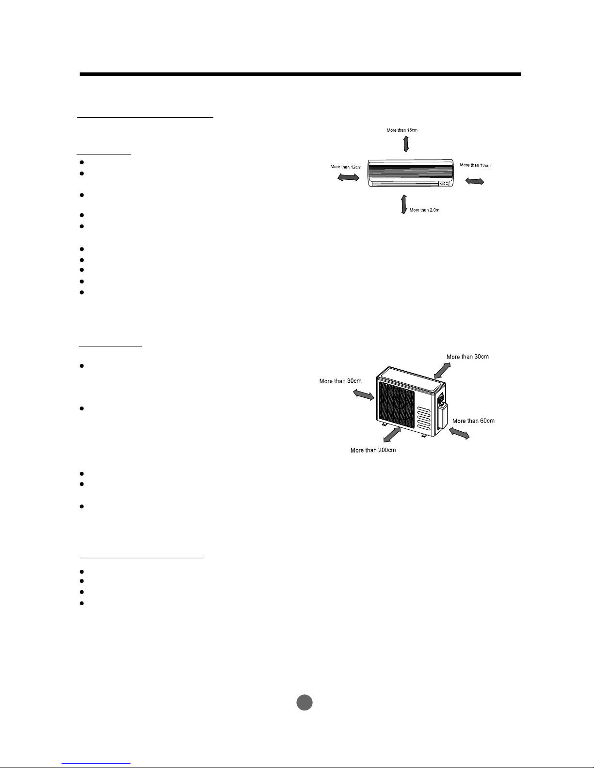
Selectinginstallationplace
Readcompletely,thenfollowstepbystep.
Indoorunit
Donotexposetheindoorunittoheatorsteam.
Selectaplacewheretherearenoobstacles
infrontoraroundtheunit.
Makesurethatcondensationdrainagecan
beconvenientlyroutedaway.
Donotinstallnearadoorway.
Ensurethatthespaceontheleftandright
oftheunitismorethan12cm.
Useastudfindertolocatestudstopreventunnecessarydamagetothewall.
Theindoorunitshouldbeinstalledonthewallataheightof2.0metresormorefromthefloor.
Theindoorunitshouldbeinstalledallowingaminimumclearanceof15cmfromtheceiling.
Anyvariationsinpipelengthwill/mayrequireadjustmenttorefrigerantcharge.
Thereshouldnotbeanydirectsunlight.Otherwise,thesunwillfadetheplasticcabinetand
affectitsappearance.Ifunavoidable,sunlightpreventionshouldbetakenintoconsideration.
Outdoorunit
Ifanawningisbuiltovertheoutdoorunitto
preventdirectsunlightorrainexposure,
makesurethatheatradiationfromthe
condenserisnotrestricted.
Ensurethattheclearancearoundtheback
oftheunitismorethan30cm
.Thefrontoftheunitshould
havemorethan200cmofclearanceandthe
connectionside(rightside)shouldhavemore
than60cmofclearance.
Donotplaceanimalsandplantsinthepathoftheairinletoroutlet.
Taketheairconditionerweightintoaccountandselectaplacewherenoiseandvibration
willnotbeanissue.
Selectaplacesothatthewarmairandnoisefromtheairconditionerdonotdisturbneighbors.
Iftheoutdoorunitisinstalledonaroofstructure,besuretoleveltheunit.
Ensuretheroofstructureandanchoringmethodareadequatefortheunitlocation.
Consultlocalcodesregardingrooftopmounting.
Iftheoutdoorunitisinstalledonroofstructuresorexternalwalls,thismayresultin
excessivenoiseandvibration,andmayalsobeclassedasanonserviceableinstallation.
andleftsideis
morethan30cm
Rooftopinstallation:
INSTALLATIONINSTRUCTIONS
Fig.2
Fig.1
1.Wall-mountedtype

4
Accessories
INSTALLATIONINSTRUCTIONS
Note: Excepttheabovepartsprovided,theotherpartsneededduringinstallationyoumust
purchase.
Levelgauge
Screwdriver
Electricdrill,Holecoredrill(65φ mm)
Flaringtoolset
Specifiedtorquewrenches:1.8kgf.m,4.2kgf.m,
5.5kgf.m,6.6kgf.m(differentdependingonmodelNo.)
Spanner(halfunion)
Hexagonalwrench(4mm)
Gas-leakdetector
Toolsneededforinstallation:
Vacuumpump
Gaugemanifold
Usersmanual
Thermometer
Multimeter
Pipecutter
Measuringtape
Partsyoumustpurchase
Consultthetechnician
forthepropersize.
6.35
9.53
12.7
6
2
Self-tappingScrewBST2.9X10
Remotecontroller
InstallationPlate
NameofAccessories
Self-tappingScrewAST3.9X25
Seal(forcooling&heatingmodelsonly)
DrainJoint
Magneticring
(Hitchitontheconnectivecablebetweenindoor
unitandoutdoorunitafterinstallation.)
Transferconnector
()
(Pipesizedifferfromappliancetoappliance.
Tomeetdifferentpipesizerequirement,sometimes
thepipeconnectionsneedthetransferconnector
toinstallontheoutdoorunit.)
NOTE:
Packedwiththeindoorunit
Connecting
pipe
Assembly
Liquidside
PlasticExpansionSheath
Number
Qty/oneunit’
Gasside
7
Remotecontrollerholder
1
(forcooling&heatingmodelsonly)
1
5-8
(dependingonmodels)
5-8
(dependingonmodels)
1
1
Optionalpart
(onepiece/onecable)
1
(onsomemodels)
1
5
4
9
11
10
8
3
2
1
Optional
parts

Thisillustrationisforexplanationpurposesonly.
Theactualshapeofyouraircondtionermaybe
slightlydifferent.
Copperlinesmustbeinsulatedindependently
Useastudfindertolocatestudstoprevent
unnecessarydamagetothewall.
Aminimumpiperunof3metresisrequired
tominimisevibration&excessivenoise.
TwooftheA,BandCdirectionsshouldbe
freefromobstructions.
CAUTION
INSTALLATIONINSTRUCTIONS
5
CAUTIONS
One-Two
One-Three
One-Four
One-Five
Remote
controller
Remote
controller
Remote
controller
Remote
controller
Morethan15cm
Remote
controller
A
B
C
Airout
Loopa
connective
cable
1
2
3
4
5
6
Fig.3
6
INSTALLATIONINSTRUCTIONS
Fig.4
Correctorientation
ofInstallationPlate
Wall
Indoor
Outdoor
Fig.6
Fig.5
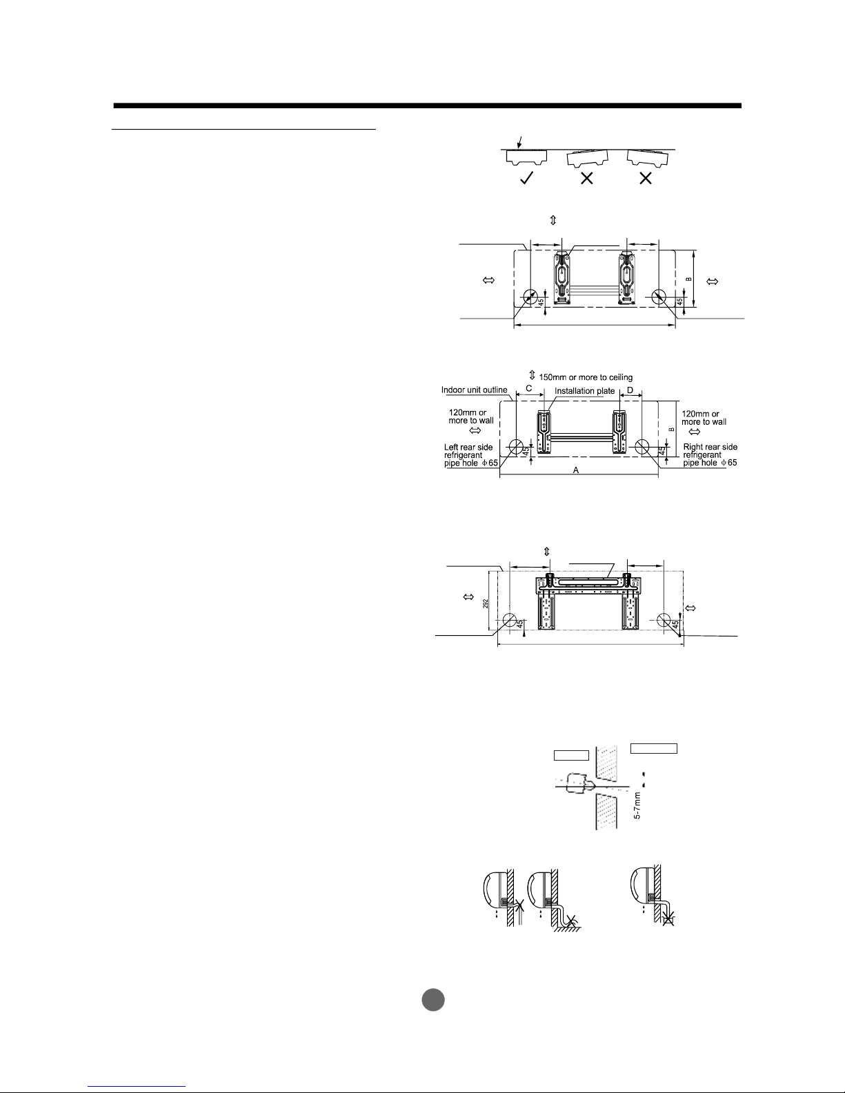
Indoorunitinstallation(wall-mountedtype)
2.Drillaholeinthewall
Note:
1.FittheInstallationPlate
1.Fittheinstallationplatehorizontally
onstructuralpartsofthewallwith
spacesaroundtheinstallationplate.
2.Ifthewallismadeofbrick,concrete
orthelike,drillfiveoreight5mmdiameter
holesinthewall.InsertClipanchorfor
appropriatemountingscrews.
3.Fittheinstallationplateonthewall
withfiveoreighttype “A” screws.
FittheInstallationPlateanddrill
holesinthewallaccordingtothe
wallstructureandcorresponding
mountingpointsontheinstallation
plate.TheInstallationPlatemaybe
slightlydifferentaccordingtothe
differentmodelsofindoorunit.
(Dimensionsarein “mm” unless
otherwisestated)
1.Determineholepositionsaccording
tothediagramdetailedinFig.5.Drill
one(1)hole(65mm)slantingslightly
tooutdoorside.
2.Alwaysusewallholeconduitwhen
drillingmetalgrid,metalplateorthelike.
φ
3.ConnectivePipeandDrainage
Installation
1.Runthedrainhoseslopingdownward.
Donotinstallthedrainhoseas
illustratedinFig.7.
Drainage
Fig.7
Donotblockwaterflowbyarise.
Donotputtheendof
drainhoseintowater.
150mmormoretoceiling
Indoorunitoutline
Installationplate
Rightrearside
refrigerant
pipehole65
φ
Leftrearside
refrigerant
pipehole65
φ
120mmor
moretowall
120mmor
moretowall
918
190
150
A
Rightrearside
refrigerant
pipehole65
φ
Installationplate
Indoorunitoutline
Leftrearside
refrigerant
pipehole65
φ
150mmormoretoceiling
120mmor
moretowall
120mmor
moretowall
ModelA(A:710,B:250,C:100,D:110)
ModelA(A:710,B:250,C:100,D:110)
ModelA(A:920,B:293,C:150,D:185)
ModelB()A:790,B:265,C:100,D:150
ModelB()A:790,B:275,C:100,D:85
ModelC()A:850,B:290,C:100,D:115
ModelB()A:995,B:293,C:150,D:200
ModelC()A:850,B:305,C:150,D:145
C
D

7
INSTALLATIONINSTRUCTIONS
1.Fortheleft-handandright-handpiping,
removethepipecoverfromtheside
panel.
2.Fortherear-right-handandrear-left-hand
piping,installthepipingasshowninFig.10.
3.Fixtheendoftheconnectivepipe.(Refer
toTighteningConnectioninREFRIGERANT
PIPINGCONNECTION)
Connectivepipeinstallation
2.Whenconnectingextensiondrainhose,
insulatetheconnectingpartofextension
drainhosewithashieldpipe,donotlet
thedrainhoseslack.
Right-handpiping
Left-handpiping
Rear-rightpiping
Rear-leftpiping
Fig.8
Fig.9
Fig.10
4.Pipingandwrapping
Bundlethetubing,connectingcable,anddrain
hosewithtapesecurely,evenlyasshownin
Fig.11.
Becausethecondensedwaterfromrearofthe
indoorunitisgatheredinpondingboxandis
pipedoutofroom.Donotputanythingelsein
thebox.
Indoorunit
Connective
pipe
Piperoom
Pondingbox
Wrappingbelt
Connective
cable
Drainhose
Fig.11
Connecttheindoorunitfirst,thenthe
outdoorunit.
Donotallowthepipingtoletoutfrom
thebackoftheindoorunit.
Becarefulnottoletthedrainhoseslack.
Heatinsulatedbothoftheauxiliarypiping.
Besurethatthedrainhoseislocatedat
thelowestsideofthebundle.Locating
attheuppersidecancausedrainpan
tooverflowinsidetheunit.
Neverintercrossnorintertwistthepower
wirewithanyotherwiring.
Runthedrainhoseslopeddownwardto
drainoutthecondensedwatersmoothly.
CAUTION

8
INSTALLATIONINSTRUCTIONS
Fig.12
1.Passthepipingthroughtheholeinthe
wall.
2.Puttheupperclawatthebackofthe
indoorunitontheupperhookofthe
installationplate,movetheindoorunit
fromsidetosidetoseethatitissecurely
hooked(seeFig.12).
3.Pipingcaneasilybemadebyliftingthe
indoorunitwithacushioningmaterial
betweentheindoorunitandthewall.
Getitoutafterfinishpiping.
4.Pushthelowerpartoftheindoorunitup
onthewall,thenmovetheindoorunit
fromsidetoside,upanddowntocheck
ifitishookedsecurely.
4.Indoorunitinstallation
(R410A)
Max.50m
(R407c/R22)
Max.10m
Max.5m
(R410A)
(R407c/R22)
10.5KW
7

Settlementofoutdoorunit
Anchortheoutdoorunitwith
aboltandnut10or8tightly
andhorizontallyonaconcrete
orrigidmount.
φφ
Fig.45
Installtheoutdoorunitonarigidbaseto
preventincreasingnoiselevelandvibration.
Determinetheairoutletdirectionwherethe
dischargedairisnotblocked.Inthecasethat
theinstallationplaceisexposedtostrongwind
suchasaseaside,makesurethefanoperating
properlybyputtingtheunitlengthwisealongthe
wallorusingadustorshieldplates.
Speciallyinwindyarea,installtheunittopreventtheadmissionofwind.Ifneedsuspending
installation,theinstallationbracketshould
accordwithtechniquerequirementinthe
installationbracketdiagram.
Theinstallationwallshouldbesolidbrick,
concreteorthesameintensityconstruction,or
actionstoreinforce,dampingsupportingshould
betaken.Theconnectionbetweenbracketand
wall,bracketandtheairconditionershouldbe
firm,stableandreliable.
Besurethereisnoobstaclewhichblock
radiatingair.
Strong
wind
Fig.44
Outdoorunitinstallation
Outdoorinstallationprecaution
INSTALLATIONINSTRUCTIONS
530
560
290
335
624
366
590
333
760x590x285
845x700x320
900x860x315
990x965x345
L2(mm)
W2(mm)
Mountingdimensions
9

Fitthesealintothedrainjoint,theninsertthe
drainjointintothebasepanholeofoutdoorunit,
rotate90tosecurelyassemblethem.
Connectingthedrainjointwithanextensiondrain
hose(Locallypurchased),incaseofthewater
drainingofftheoutdoorunitduringtheheating
mode.
。
Drainjointinstallation
Seal
Drainjoint
Basepanholeof
outdoorunit
Seal
Drainpipe
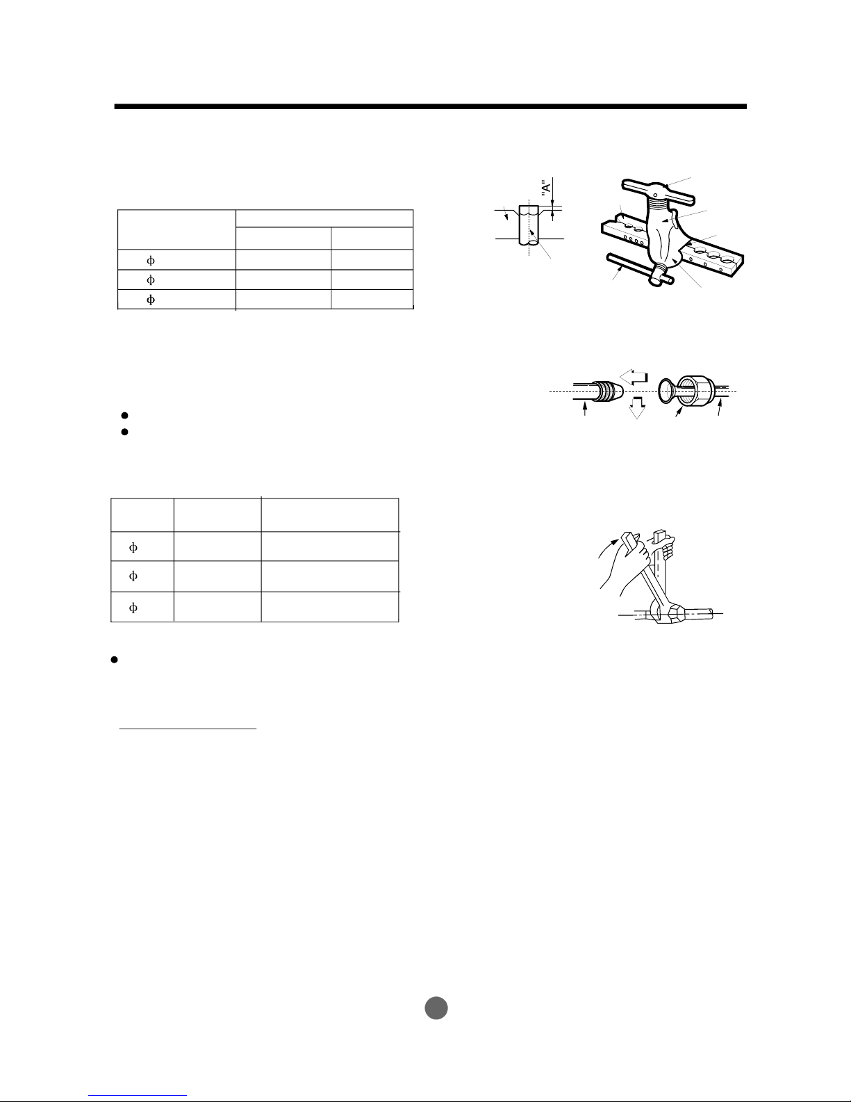
Refrigerantpipeconnection
Oblique
90
。
Roughness Burr
Maincauseforrefrigerantleakage
isduetodefectintheflaringwork.
Carryoutcorrectflaringwork
usingthefollowingprocedure:
1.Usethepipingkitaccessoryorpipes
purchasedlocally.
2.Measurethedistancebetweentheindoor
andtheoutdoorunit.
3.Cutthepipesalittlelongerthanthe
measureddistance.
4.Cutthecable1.5mlongerthanthepipe
length.
A:Cutthepipesandthecable.
1.Flaringwork
Fig.46
B:Burrremoval
1.Completelyremoveallburrsfromthecut
crosssectionofpipe/tube.
2.Puttheendofthecoppertube/pipeina
downwarddirectionasyouremoveburrsin
ordertoavoiddroppingburrsintothetubing.
Pipe
Reamer
Pointdown
Fig.47
Fig.48
C:Puttingnuton
Removeflarenutsattachedtoindoorand
outdoorunit,thenputthemonpipe/tube
havingcompletedburrremoval.(notpossible
toputthemonafterflaringwork)
Flarenut
Coppertube
Fig.49
REFRIGERANTPIPECONNECTION
(1)
(2)
NOTE:Thedrainjointdifferfromappliance
toappliance.
10
ELECTRICALWORK
Bar
Copperpipe
Clamphandle
Redarrowmark
Cone
Yoke
Handle
Bar
Fig.50
D:Flaringwork
Firmlyholdcopperpipeinadieinthe
dimensionshowninthetablebelow.
Caution
Alignthecenterofthepipes.
Sufficientlytightentheflare
nutwithfingers,andthentighten
itwithaspannerandtorquewrench
asshowninFig.51&52.
TighteningConnection
Excessivetorquecanbreaknut
dependingoninstallationconditions.
Outerdiam.
(mm)
A(mm)
Max.
Min.
6.35 1.3 0.7
9.53
1.6 1.0
12.7
1.8
1.0
Fig.52
Indoorunittubing Flarenut Pipings
Fig.51
ElectricsafetyregulationsfortheinitialInstallation
1.Ifthereisserioussafetyproblemaboutthepowersupply,thetechniciansshouldrefuse
toinstalltheairconditionerandexplaintotheclientuntiltheproblemissolved.
2.Powervoltageshouldbeintherangeof90%~110%ofratedvoltage.
3.Thecreepageprotectorandmainpowerswitchwitha1.5timescapacityofMax.Current
oftheunitshouldbeinstalledinpowercircuit.
4.Ensuretheairconditionerisgroundedwell.
7.Anindividualbranchcircuitandsinglereceptacleusedonlyforthisairconditionermustbeavailable.
5.AccordingtotheattachedElectricalConnectionDiagramlocatedonthepaneloftheoutdoor
unittoconnectthewire.
6.Allwiringmustcomplywithlocalandnationalelectricalcodesandbeinstalled
byqualifiedandskilledelectricians.
12.7
1.8
1.0
Electricalwork
Outer
diam.
Tightening
torque(N.cm)
Additionaltightening
torque(N.cm)
6.35
12.7
9.52
1500
(153kgf.cm)
1600
(163kgf.cm)
3500
(357kgf.cm)
3600
(367kgf.cm)
2500
(255kgf.cm)
2600
(265kgf.cm)
11
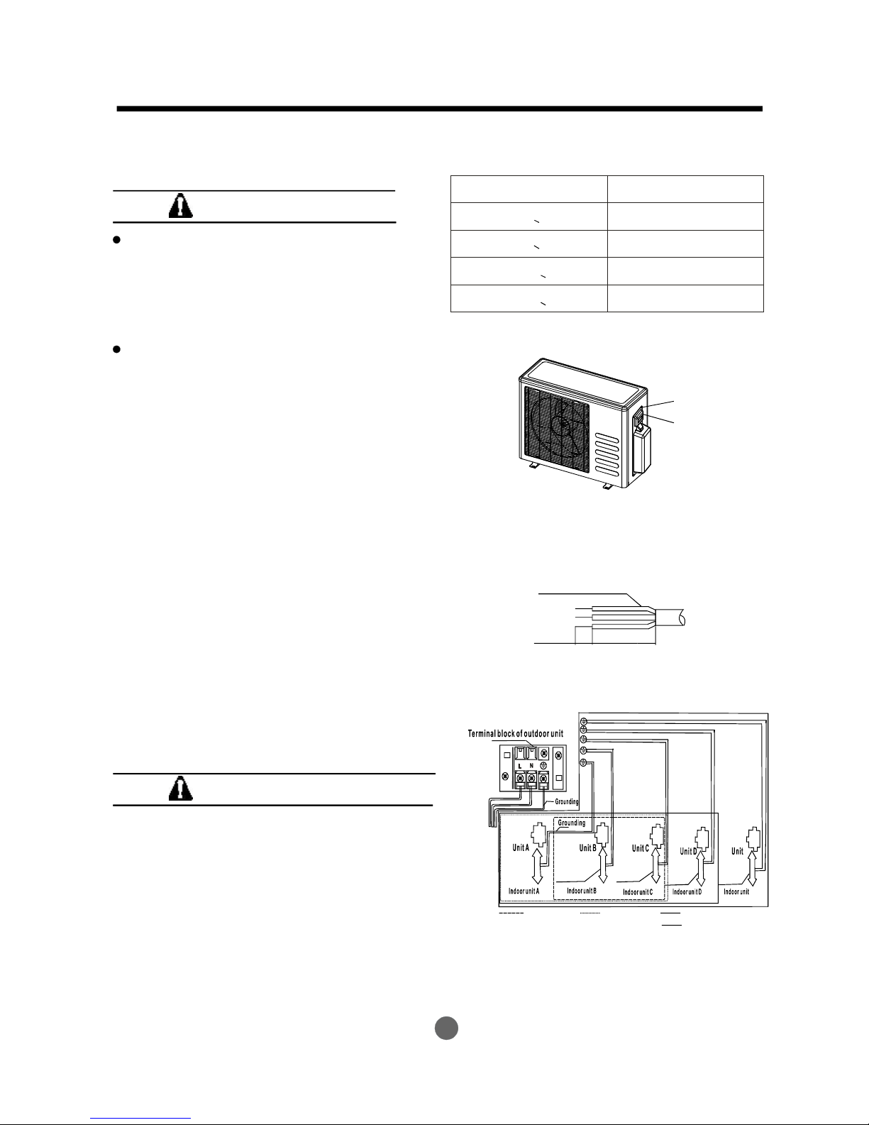
ELECTRICALWORK
Fig.53
Connectthecabletotheoutdoorunit
1.Removetheelectricalcontrolboardcover
fromtheoutdoorunitbylooseningthescrew
asshowninFig.53.
2.Connecttheconnectivecablestothe
terminalsasidentifiedwiththeirrespective
matchednumbersontheterminalblockof
indoorandoutdoorunits.
3.Securethecableontothecontrolboardwith
thecordclamp.
4.Topreventtheingressofwater,fromaloop
oftheconnectivecableasillustratedinthe
installationdiagramofindoorandoutdoor
units.
5.Insulateunusedcords(conductors)with
PVC-tape.Processthemsotheydonot
touchanyelectricalormetalparts.
Wiringconnection
NOTE:Beforeperforminganyelectrical
work,turnoffthemainpowertothesystem.
ConnectionCable
10mm
40mm
CAUTIONS
Donottouchthecapacitorevenifyou
havedisconnectedthepowerforthereis
stillhighvoltagepoweronit,orelectric
shockhazardmayoccur.Foryoursafety,
youshouldstartrepairingatleast5minutes
laterafterthepowerisdisconnected.
ThepowerissuppliedfromtheOutdoor
Unit.TheIndoorUnitsareconnected
withsignalwiresorpowercordsare
connectedreliablyandcorrectly,orthe
airconditionercouldnotrunnormally.
Fig.54
CAUTIONS
Makesuretoconnecttheindoorunit(A,B,C,D,
E)totheHiandLovalveandterminalsofsignal
wires(A,B,C,D,E)ofoutdoorunitasidentified
withtheirrespectivematchedconnection.
Wrongwiringconnectionsmaycausesome
electricalpartstomalfunction.
Minimumnorminalcross-sectionalarea
ofconductors:
Ratedcurrentofappliance
(A)
Nominalcross-sectional
area(mm)
2
>3and<6
>6and<10
>10and<16
>16and<25
0.75
1
1.5
2.5
Screw
Cover
Connectivecable
ofindoorunitand
outdoorunit
Connectivecable
ofindoorunitand
outdoorunit
Connectivecable
ofindoorunitand
outdoorunit
Connectivecable
ofindoorunitand
outdoorunit
Connectivecable
ofindoorunitand
outdoorunit
One-two One-three One-four
One-five
POWER
E
E
12

POWER
L
N
TOA
TOB
L(A)
L(B)
N(A) N(B)
S(A)
S(B)
One-twomodels:
One-threemodels:
One-fourmodels:
One-fivemodels:
Fig.55
L
N
S(A)
L(A)
N(A)
TOA
TOA
L
N
L(A)
N(A)
S(A)
NOTE:pleaserefertothefollowingfigures,iftheclientwantwirebythemselves.
ELECTRICALWORK
L2
S
L2L1L1
SUPPLY
S
TOA
L2
L1
L1
L2
SUPPLY
Y/G
Y/G
Y/G
TOA
TOA
TOB
L1
L2
SUPPLY
SUPPLY
Y/G
Y/G
Y/G
Y/G
Y/G
Y/G
TOB
TOC
TOC
TOD
TOD
TOE
L1
L2
ModelA
ModelA
ModelA
ModelA
ModelB
Magneticring(notsupplied,
optionalpart)
ModelB
ModelB
ModelB
L N
TOB
TOA
L(B)
N(B)
S(B)
L(A)
N(A)
S(A)
(Usedtohitchtotheconnective
cableofindoorandoutdoor
unitsafterinstallation.)
13

Aftertheconfirmationoftheaboveconditions,preparethewiringasfollows:
1)Neverfailtohaveanindividualpowercircuitspecificallyfortheairconditioner.Asfor
themethodofwiring,beguidedbythecircuitdiagrampostedontheinsideofcontrol
cover.
2)Thescrewwhichfastenthewiringinthecasingofelectricalfittingsareliabletocome
loosefromvibrationstowhichtheunitissubjectedduringthecourseof
transportation.Checkthemandmakesurethattheyarealltightlyfastened.(Ifthey
areloose,itcouldcauseburn-outofthewires.)
3)Specificationofpowersource.
4)Confirmthatelectricalcapacityissufficient.
5)Seetothatthestartingvoltageismaintainedatmorethan90percentoftherated
voltagemarkedonthenameplate.
6)Confirmthatthecablethicknessisasspecifiedinthepowersourcespecification.
7)Alwaysinstallanearthleakagecircuitbreakerinawetormoistarea.
8)Thefollowingwouldbecausedbyvoltagedrop.
Vibrationofamagneticswitch,whichwilldamagethecontactpoint,fusebreaking,disturbanceofthe
normalfunctionoftheoverload.
9)Themeansfordisconnectionfromapowersupplyshallbeincorporatedinthefixed
wiringandhaveanairgapcontactseparationofatleast3mmineachactive(phase)
conductors.
Airandmoistureintherefrigerantsystemhaveundesirableeffectsasindicatedbelow:
Pressureinthesystemrises.
Operatingcurrentrises.
Coolingorheatingefficiencydrops.
Moistureintherefrigerantcircuitmayfreezeandblockcapillarytubing.
Watermayleadtocorrosionofpartsintherefrigerationsystem.
Therefore,theindoorunitandtubingbetweentheindoorandoutdoorunitmustbeleaktested
andevacuatedtoremoveanynoncondensablesandmoisturefromthesystem.
●
●
●
●
●
Airpurgingwithvacuumpump
●
Preparation
Checkthateachtube(bothliquidandgassidetubes)betweentheindoorandoutdoorunits
havebeenproperlyconnectedandallwiringforthetestrunhasbeencompleted.Remove
theservicevalvecapsfromboththegasandtheliquidsideontheoutdoorunit.Notethat
boththeliquidandthegassideservicevalvesontheoutdoorunitarekeptclosedatthis
stage.
●
Pipelengthandrefrigerantamount:
Connective
pipelength
Lessthan5m
Morethan5m
Airpurging
method
Usevacuum
pump.
Usevacuum
pump.
Additionalamountofrefrigeranttobecharged
AIRPURGING
Airpurging
R22:(Pipelength-5m)x30g/m
R410A:(Pipelength-5m)x15g/m
R407c:(Pipelength-5m)x30g/m
14

AIRPURGING
Whenrelocatetheunittoanotherplace,
performevacuationusingvacuumpump.
Makesuretherefrigerantaddedintotheair
conditionerisliquidforminanycase.
(NotapplicabletotheunitsadoptfreonR22)
Openthevalvestemuntilithitsagainstthe
stopper.Donottrytoopenitfurther.
Securelytightenthevalvestemcapwitha
spannerorthelike.
Valvestemcaptighteningtorque(See
Tighteningtorquetableinpreviouspage).
Outdoor
unit
Indoor
unit
Refrigerant
Flarenut
Stopper
Cap
Valvebody
Packedvalve Halfunion
Gasside
Liquidside
A
C
D
B
Valvestem
Fig.56
Fig.57
WhenUsingtheVacuumPump
(Formethodofusingamanifoldvalve,refer
toitsoperationmanual.)
1.Completelytightentheflarenuts,A,B,C,D,
valvechargehosetoa
chargeportofthelow-pressurevalveonthe
gaspipeside.
2.Connectthechargehoseconnectiontothe
vacuumpump.
3.FullyopenthehandleLoofthemanifoldvalve.
4.Operatethevacuumpumptoevacuate.After
slightlyloosetheflarenut
oftheLovalveonthegaspipeside
checkthattheairisentering(Operationnoise
pumpchangesanda
commeterindicates0insteadofminus)
5.Aftertheevacuationiscomplete,fullyclose
manifoldvalveandstop
theoperationofthevacuumpump.Make
evacuationfor15minutesormore
compoundmeterindicates
-76cmHg(-1x10Pa).
6.TurnthestemofthepackedvalveBabout
45counterclockwisefor6~7secondsafter
thegascomingout,thentightentheflarenut
again.Makesurethepressuredisplayinthe
pressureindicatorisalittlehigherthanthe
atmospherepressure.
7.RemovethechargehosefromtheLow
pressurechargehose.
8.FullyopenthepackedvalvestemsBandA.
9.Securelytightenthecapofthepackedvalve.
connectthemanifold
startingevacuation,
and
ofthevacuum
pound
thehandleLoofthe
andcheck
thatthe
5
o
Manifoldvalve
Compoundmeter
-76cmHg
HandleLo
HandleHi
Chargehose
Chargehose
Vacuumpump
Pressuregauge
Lowpressurevalve
Fig.58
Cautioninhandlingthepackedvalve
15

Performtheelectricsafecheckafter
completinginstallation:
1.Insulatedresistance
Theinsulatedresistancemustbemorethan
2M.
2.Groundingwork
Afterfinishinggroundingwork,measurethe
groundingresistancebyvisualdetectionand
groundingresistancetester.Makesurethe
groundingresistanceislessthan4.
3.Electricalleakagecheck(performingduring
testrunning)
Duringtestoperationafterfinishinginstallation,
theservicemancanusetheelectroprobeand
multimetertoperformtheelectricalleakage
check.Turnofftheunitimmediatelyifleakage
happens.Checkandfindoutthesolution
waystilltheunitoperateproperly.
Ω
Ω
A:LopackedvalveB:Hipackedvalve
CandDareendsofindoorunitconnection.
CAUTION
Electricalsafetycheck●
Gasleakcheck●
1.
Applyasoapwateroraliquidneutral
detergentontheindoorunitconnection
oroutdoorunitconnectionsbyasoft
brushtocheckforleakageofthe
connectingpointsofthpiping.Ifbubbles
comeout,thepipeshaveleakage.
2.
Soapwatermethod:
Leakdetector
Usetheleakdetectortocheckforleakage.
Safetyandleakagecheck
15
Indoorunit
checkpoint
Outdoorunit
checkpoint
n
m
k
j
i
h
A
B
C
a
c
b
d
e
f
a,b,c,d,h,i,j,karepointsforone-twotype.
a,b,c,d,e,f,,h,i,j,k,m,narepointsforone-threetype.
A,B,C,Darepointsforone-fourtype.
A,B,C,D,Earepointsforone-fivetype.
Indoorunit
checkpoint
Outdoorunit
checkpoint
AIRPURGING
Fig.59
Fig.60
NOTE: Theillustrationisforexplanation
purposeonly.TheactualorderofA,B,C
DandEonthemachinemaybeslightly
differentfromtheunityoupurchased.The
actualshapeshallprevail.
E
16

Testrunning
Performtestoperationaftercompletinggasleakcheckattheflarenutconnectionsand
electricalsafetycheck.
Checkthatalltubingandwiringhavebeenproperlyconnected.
Checkthatthegasandliquidsideservicevalvesarefullyopen.
1.Connectthepower,presstheON/OFFbuttonontheremotecontrollertoturntheuniton.
2.UsetheMODEbuttontoselectCOOL,HEAT,AUTOandFANtocheckifallthefunctions
workswell.
3.Whentheamienttemperatureistoolow(lowerthan17C),theunitcannotbecontrolledby
theremotecontrollertorunatcoolingmode,manualoperationcanbetaken.Manual
operationisusedonlywhentheremotecontrollerisdisableormaintenancenecessary.
PresstheManualcontrolbuttontoselecttheAUTOorCOOL,theunitwilloperateunder
ForcedAUTOorCOOLmode(seeUserManualfordetails).
4.Thetestoperationshouldlastabout30minutes.
Holdthepanelsidesandliftthepaneluptoanangleuntilitremainsfixedwithaclicking
sound.
Manualcontrol
Button
TESTRUNNING
Fig.61
Manualcontrol
button
AUTO/COOL
17
Beforeusingyourairconditioner,pleaseread
thismanualcarefullyandkeepitforfuturereference.
INVERTERONE-TWO/ONE-THREE/ONE-FOURSPLIT-TYPE
ROOMAIRCONDITIONER
ReadThisManual
Insideyouwillfindmanyhelpfulhintsonhow
touseandmaintainyourairconditionerproperly.
Justalittlepreventativecareonyourpartcan
saveyouagreatdealoftimeandmoneyover
thelifeofyourairconditioner.You'llfindmany
answerstocommonproblemsinthechartof
troubleshootingtips.Ifyoureviewthechartof
TroubleshootingTipsfirst,youmaynotneed
tocallforservice.
18

SOCIABLEREMARK
DISPOSAL: Donotdisposethisproductasunsortedmunicipalwaste.Collectionofsuchwaste
separatelyforspecialtreatmentisnecessary.
Itisprohibitedtodisposeofthisapplianceindomestichouseholdwaste.
Fordisposal,thereareseveralpossibilities:
A)Themunicipalityhasestablishedcollectionsystems,whereelectronicwastecanbedisposedofat
leastfreeofchargetotheuser.
B)Whenbuyinganewproduct,theretailerwilltakebacktheoldproductatleastfreeofcharge.
C)Themanufacturewilltakebacktheoldappliancefordisposalatleastfreeofchargetotheuser.
D)Asoldproductscontainvaluableresources,theycanbesoldtoscrapmetaldealers.
Wilddisposalofwasteinforestsandlandscapesendangersyourhealthwhenhazardoussubstances
leakintotheground-waterandfindtheirwayintothefoodchain.
WhenusingthisairconditionerintheEuropeancountries,thefollowinformationmustbe
followed:
19

SAFETYPRECAUTIONS
Topreventinjurytotheuserorotherpeopleandpropertydamage,thefollowinginstructionsmustbe
followed.Incorrectoperationduetoignoringofinstructionsmaycauseharmordamage.
Theseriousnessisclassifiedbythefollowingindications.
Thissymbolindicatesthepossibilityofdeathorseriousinjury.
Meaningsofsymbolsusedinthismanualareasshownbelow.
WARNING
Alwaysdothis.
Neverdothis.
CAUTION
Thissymbolindicatesthepossibilityofinjuryordamagetoproperty.
Connectwiththepower
properly.
Donotmodifypowercord
lengthorsharetheoutlet
withotherappliances
Alwaysensureeffective
earthing.
Disconnectthepowerif
strangesounds,smell,or
smokecomesfromit.
Ventilateroombeforeoperatingair
conditionerifthereisagasleakagefrom
anotherappliance.
Otherwise,itmaycauseelectric
shockorfireduetoheat
generation.
excess
Itmaycauseelectricshockor
fireduetoheatgeneration.
Noearthingmaycauseelectric
shock.
Itmaycausefireandelectric
shock.
Itmaycauseexplosion,fireand,burns.
Itmaycauseelectricshockorfire
duetoheatgeneration.
Itmaycauseelectricshock.
Itmaycausefailureofmachine
orelectricshock.
Itcontainscontaminantsand
couldmakeyousick.
Itmaycausefireandelectric
shock.
Itmaycauseelectricshockorfire.
Thiscoulddamageyourhealth.
Noinstallationmaycausefire
andelectricshock.
Itmaycauseelectricshock.
Itmaycauseanexplosionorfire.
Itmaycausefailureandelectricshock.
Donotoperateorstopthe
unitbyswitchingonoroff
thepower.
Donotoperatewithwet
handsorindamp
environment.
Donotallowwatertorun
intoelectricparts.
Donotdrinkwaterdrained
fromairconditioner.
Donotusethepowercord
closetoheatingappliances.
Donotdamageorusean
unspecifiedpowercord.
Donotdirectairflowat
roomoccupantsonly.
Alwaysinstallcircuit
breakerandadedicated
powercircuit.
Donotopentheunit
duringoperation.
Donotusethepowercordnear
flammablegasorcombustibles,such
asgasoline,benzene,thinner,etc.
Donotdisassembleormodifyunit.
WARNING
Usethecorrectlyrated
breakerorfuse.
Thereisriskoffireorelectric
shock.
20

SAFETYPRECAUTIONS
CAUTION
Whentheairfilteristobe
removed,donottouchthe
metalpartsoftheunit.
Itmaycauseaninjury.
Donotcleanunitwhen
powerisonasitmaycause
fireandelectricshock,itmay
causeaninjury.
Operationwithwindows
openedmaycausewetting
ofindoorandsoakingof
householdfurniture.
Whentheunitistobe
cleaned,switchoff,andturn
offthecircuitbreaker.
Stopoperationandclose
thewindowinstormor
hurricane.
Usecautionwhenunpacking
andinstalling.Sharpedges
couldcauseinjury.
Donotcleantheair
conditionerwithwater.
Watermayentertheunitand
degradetheinsulation.Itmay
causeanelectricshock.
Thiscouldinjurethepetor
plant.
Donotputapetorhouse
plantwhereitwillbe
exposedtodirectairflow.
Ventilatetheroomwell
whenusedtogether
withastove,etc.
Anoxygenshortage
mayoccur.
Donotusethisairconditionertopreserveprecisiondevices,food,pets,
plants,andartobjects.
Itmaycausedeterioration
ofquality,etc.
Itmaycausefailureof
productorfire.
Donotusefor
specialpurposes.
Turnoffthemainpower
switchwhennotsing
theunitforalongtime.
u
Ifwaterentersthe
unit,turntheunitoff
anddisconnectthe
power,contacta
qualifiedservice
technician.
Itmaycausefailureof
applianceoraccident.
Appearancemaybe
deterioratedduetochange
ofproductcoloror
scratchingofitssurface.
Donotplaceobstacles
aroundair-inletsorinside
ofair-outlet.
Donotusestrongdetergent
suchaswaxorthinner.Use
asoftclothforcleaning.
Ifbracketisdamaged,there
isconcernofdamagedueto
fallingofunit.
Thereisdangeroffireor
electricshock.
Ensurethattheinstallationbracketof
theoutdoorapplianceisnotdamaged
duetoprolongedexposure.
Donotplaceheavyobjectonthe
powercordandtakecaresothat
thecordisnotcompressed.
Operationwithoutfilters
maycausefailure.
Alwaysinsertthefilters
securely.Cleanfilter
onceeverytwoweeks.
21

OPERATINGINSTRUCTIONS
Indoorunit
Outdoorunit
Identificationofparts
Indoorunit
Outdoorunit
One-twin
One-three
One-four
9
10.Drainhose,refrigerantconnectingpipe
11.Connectivecable
12.Stopvalve
13.Fanhood
10
11
12
13
1.Panelframe
2.Rearairintakegrille
3.Frontpanel
4.AirPurifyingfilter&Airfilter(behind)
5.Horizontallouver
6.LCDdisplaywindow
7.Verticallouver
8.Manualcontrolbutton(behind)
9. Remotecontrollerholder
22

AUTOoperationdisplay
DisplayedduringAutooperation.
OPERATIONdisplay
Displayedwhentheairconditionerisin
operation.
DEFROSToperationdisplay
(ForHeating&Coolingmodelonly):
Displayedwhentheairconditionerstarts
defrostingautomaticallyorwhenthewarm
aircontrolfeatureisactivatedinheating
operation.
TIMERdisplay
DisplayedduringTimeroperation.
TURBOoperationdisplay
DisplayedwhenselectTURBOfunction
oncoolingoperationoronheating
operation.
DIGITALDISPLAY
Displaysthecurrentsettingtemperaturewhentheairconditionerisin
operation.
FANSPEEDdisplay
Displayedtheselectedfanspeed:
LOW(),MED()and
HIGH().
OPERATINGINSTRUCTIONS
Thisdisplayisseparatedintofivezones.
Thezonesilluminatebasedonthe
compressorcurrentfrequency.Forexample,
higherfrequencywillilluminatemorezones.
Frequencyindicationlamp
23

Manuloperationcanbeusedtemporarilyincaseyoucannotfindtheremotecontrolleror
testrunningpurposeormaintenancenecessary.
OPERATINGINSTRUCTIONS
Manualoperation
NOTE:ThismanualdoesnotincludeRemoteControllerOperations,seethe
<<RemoteControllerInstruction>>packedwiththeunitfordetails.
Operatingtemperature
Manual
controlbutton
AUTO/COOL
ModelA
ModelB
Manual
controlbutton
ForDUCTandCEILINGtype,CASSETTE
type,CEILINGandFLOORtypeandFLOORand
STANDINGtype,pleaserefertothepreviouspages
tooperatetheManualbutton.
NOTE:
Openandliftthefrontpaneluptoanangle
untilitremainsfixedwithaclickingsound.
Forsomemodels,themanualcontrolbuttonis
locatedatthebottomoftheunit.
Closethepanelfirmlytoitsoriginal
position.
Onepressofthemanualcontrolbuttonwill
leadtotheforcedAUTOoperation.Ifpress
thebuttontwicewithinfiveseconds,theunit
willoperateunderforcedCOOLoperation.
1
3
2
NOTE:Theunitmustbeturnedoffbefore
operatingthemanualcontrolbutton.Ifthe
unitisoperational,continuepressingthe
manualcontrolbuttonuntiltheunitisoff.
Mode
Temperature
Roomtemperature
Outdoortemperature
1.Optimumperformancewillbeachievedwithintheseoperatingtemperatures.Ifair
conditionerisusedoutsideoftheaboveconditions,certainsafetyprotectionfeatures
mightcomeintooperationandcausetheunittofunctionabnormally.
2.Iftheairconditioneroperatesinaroomwhoserelativehumidityislessthan80%
thesurfaceoftheairconditionermayattractcondensation.Pleasesetsthevertical
airflowlouvertoitsmaximumangle(verticallytothefloor),andsetHIGHfanmode.
Suggestion: FortheunitadoptsanElectricHeater,whentheoutsideambienttemperature
isbelow0C(32F),westronglyrecommendyoutokeepthemachinepluggedinorderto
guaranteeitrunningsmoothly.
OO
NOTE:
Coolingoperation
Heatingoperation Dryingoperation
1762
-15505122
Forthemodelswithlow
temperaturecoolingsystem
050
32122
3088
-1534
592
1050
050
32122
Manualcontrolbutton
24

OPERATINGINSTRUCTIONS
Airflowdirectioncontrol
Adjusttheairflowdirectionproperlyotherwise,it
mightcausediscomfortorcauseunevenroom
temperatures.
Adjustthehorizontallouverusingtheremote
controller.
Adjusttheverticallouvermanually.
Tosettheverticalairflow(Up--Down)direction
Performthisfunctionwhiletheunitisinoperation.
Usetheremotecontrollertoadjusttheairflow
direction.Thehorizontallouvercanbemovedat
arangeof6Oforeachpress,orswingupanddown
automatically.PleaserefertotheREMOTE
CONTROLLEROPERATIONMANUALfordetails.
Tosetthehorizontalairflowdirection(left-right)
Movetheverticallouvermanuallytoadjusttheair
flowinthedirectionyouprefer.
Beforeadjustingtheverticallouvers,
thesupplypowermustbedisconnected.
Forsomemodels,theverticallouvercanbeadjusted
byusingtheremotecontroller.Pleaserefertothe
REMOTECONTROLLEROPERATIONMANUAL
fordetails.
IMPORTANT:
Donotoperatetheairconditionerforlongperiodswith
theairflowdirectionsetdownwardincoolingor
dehumidifyingmode.Otherwise,condensationmay
occuronthesurfaceofthehorizontallouvercausing
moisturetodropontothefloororonfurnishings.
Donotmovethehorizontallouvermanuallyunlessitis
necessary.Alwaysusetheremotecontroller.
Whentheairconditionerisstartedimmediatelyafterit
wasstopped,thehorizontallouvermightnotmovefor
approximately10seconds.
Openangleofthehorizontallouvershouldnotbeset
toosmall,asCOOLINGorHEATINGperformancemay
beimpairedduetotoorestrictedairflowarea.
Donotoperateunitwithhorizontallouverinclosed
position.
Whentheairconditionerisconnectedtopower(initial
power),thehorizontallouvermaygenerateasoundfor
10seconds,thisisanormaloperation.
CAUTION
,,
,,
,,
,,
Range
Range
Vertical
louver
(threeplaces)
25

AUTOoperation
operation
DRYINGoperation
WhenyousettheairconditionerinAUTOmode,
itwillautomaticallyselectcooling,heating(cooling
/heatingmodelsonly),orfanonlyoperation
dependingonwhattemperatureyouhaveselected
andtheroomtemperature.
Theairconditionerwillcontrolroomtemperature
automaticallyroundthetemperaturepointsetby
you.
IftheAUTOmodeisuncomfortable,youcan
selectdesiredconditionsmanually.
Whenyoupush tononremotecontroller
duringcooling,heating(coolingonlytypewithout),
orAUTOoperation,theairconditionerwill
automaticallyincrease(cooling)ordecrease
(heating)1perhour.
Thesettemperaturewillbesteady2hourslater.
Andtheairconditionerwillbetimeroffin7hours.
Thefanspeedwillbeautomaticallycontrolled.
Thisfeaturecanmaintainthemostcomfortable
temperatureandsavemoreenergyforyou.
Thefanspeedwillbeautomaticallycontrolled
underdryoperation.
Duringthedryoperation,iftheroomtemperature
islowerthan10C,thecompressorstopsoperation
andrestartsuntiltheroomtemperatureisabove
12C.
℃
O
O
OPERATINGINSTRUCTIONS
Howtheairconditionerworks
1hour
1hour
Set
Temperature
Cooling
1℃
1℃
Heating
operation
1℃
1℃
1hour
1hour
Set
Temperature
7hourstimeroff
7hourstimeroff
ECONOMY
ECONOMY
ECONOMY but
26
operationECONOMY
Whilesimultaneouslyoperatingtwoindoorunitsormore,makesuretheoperationmodeswill
notconflictwitheachother.Theheatmodeclaimsprecedenceoverallothermodes.
Forexample:Iftheunitintiallystartedoperatesundercool(orfan)mode,theotherunitscan
operateunderanymodeexceptheat.Ifoneoftheunitselectsheatmode,theotheroperating
unitswillstopoperationanddiplayP5(Fortheunitswithdisplaywindowonly)ortheAutoand
Operationindicationlightflashrapidly,theDefrostindicationlightturnoff,theTimerindication
lightremainon(Fortheunitswithoutdisplaywindow),ortheDefrostandAlarmindicationlight(
ifapplicable)illuminate,theOperationindicationlightflashesrapidlyandtheTimerindication
lightturnsoff(FortheFloorandstandingtype).
Iftheunit
intiallystartedoperatesunderheatmode,theotherunitscanoperateunderheatmodeonly.
OPERATINGINSTRUCTIONS
Operationmodeselection
Toachieveoptimalperformance,pleasenotethefollowing:
Adjusttheairflowdirectioncorrectlysothatitisnotdirectedonpeople.
Adjustthetemperaturetoachievethehighestcomfortlevel.Donotadjusttheunittoexcessive
temperaturelevels.
ClosedoorsandwindowsonCOOLorHEATmodes,orperformancemaybereduced.
UseTIMERONbuttonontheremotecontrollertoselectatimeyouwanttostartyourairconditioner.
Donotputanyobjectnearairinletorairoutlet,astheefficiencyoftheairconditionermaybereduced
andtheairconditionermaystoprunning.
Cleantheairfilterperiodically,otherwisecoolingorheatingperformancemaybereduced.
Donotoperateunitwithhorizontallouvreinclosedposition.
Suggestion:FortheunitadoptsanElectricHeater,whentheoutsideambienttemperatureis
below0C,westronglyrecommendyoutokeepthemachinepluggedinordertoguaranteeit
runningsmoothly.
O
Optimaloperation
27

CAREANDMAINTENANCE
CleaningtheGrille,CaseandRemoteController
Aclothdampenedwithcoldwatermaybeusedon
theindoorunitifitisverydirty.Thenwipeitwitha
drycloth.
Donotuseachemicallytreatedclothordusterto
cleantheunit.
Donotusebenzine,thinner,polishingpowder,or
similarsolventsforcleaning.Thesemaycause
theplasticsurfacetocrackordeform.
Neverusewaterhotterthan40Ctocleanthefront
panel,itcouldcausedeformationofdiscoloration.
CAUTIONS
Careandmaintenance
Turnthesystemoffbeforecleaning.Toclean,wipe
withasoft,drycloth.Donotusebleachorabrasives.
NOTE:Supplypowermustbedisconnectdbefore
cleaningtheindoorunit.
FilterHandle
Acloggedairfilterreducesthecoolingefficiencyof
thisunit.Pleasecleanthefilteronceevery2weeks.
1.Lifttheindoorunitpaneluptoanangleuntilit
stopswithaclickingsound.
2.Takeholdofthehandleoftheairfilterandliftit
upslightlytotakeitoutfromthefilterholder,
thenpullitdownwards.
Cleaningtheairfilter
3.Removethefromthe
indoorunit.
Cleantheitoncetwoweeks.
Cleantheitwithavacuumcleanerorwater,
thendryitupincoolplace.
ActiveCarbon&DustFilter
.
.
WALL-MOUNTEDTYPE
28

29
CAREANDMAINTENANCE
Maintenance
Checksbeforeoperation
Ifyouplantoidletheunitforalongtime,performthe
following:
(1)Operatethefanforabouthalfadaytodrythe
insideoftheunit.
(2)Stoptheairconditioneranddisconnectpower.
(3)Theoutdoorunitrequiresperiodicmaintenance
andcleaning.Donotattempttodothisyourself.
Contactyourdealerorservicer.
Removethebatteriesfromtheremotecontroller.
Checkthatthewiringisnotbrokenoffor
disconnected.
Checkthattheairfilterisinstalled.
Checkiftheairoutletorinletisblockedafterthe
airconditionerhasnotbeenusedforalongtime.
Donottouchthemetalpartsoftheunitwhen
removingthefilter.Injuriescanoccurwhen
handlingsharpmetaledges.
Donotusewatertocleaninsidetheairconditioner.
Exposuretowatercandestroytheinsulation,
leadingtopossibleelectricshock.
Whencleaningtheunit,firstmakesurethatthe
powerandcircuitbreakerareturnedoff.
Caution
4.Removethe
SilverIonfilter/Biofilter/
VitaminCfilter)fromitssupportframe.
(Theinstallationandremovingmethodoftheair
fresheningfilterisdifferentdependingonthemodels,
seethepicturesmarkedandontheleft.
Cleantheairfresheningfilteratleastonceamonth,
andreplaceitevery4-5months.
Cleanitwithvacuumcleaner,thendryitincoolplace.
5.Installtheairfresheningfilterbackintoposition.
6.Inserttheupperportionofairfilterbackintotheunit
takingcarethattheleftandrightedgeslineup
correctlyandplacefilterintoposition.
AirFresheningFilterOptionalfilter(:
PlasmaDustcollector/
.
.
1
2
1
2

Maintenance
Ifyouplantoidletheunitforalongtime,performthefollowing:
Useadryclothtowipeoffthedustaccumulatedonrearairintakegrille,inordertoavoidthedust
blowingoutfromtheindoorunit.
Checkthatthewiringisnotbrokenoffordisconnected.
Checkthattheairfilterisinstalled.
Checkiftheairoutletorinletisblockedaftertheairconditionerhasnotbeenusedforalongtime.
1.Cleantheindoorunitandairfilter.
2.SelectFANonlymode,lettheindoorfanrunforawhiletodrytheinsideoftheunit.
3.Disconnectthepowersupplyandremovebatteryfromtheremotecontrol.
4.Checkcomponentsoftheoutdoorunitperiodically.Contactalocaldealeroracustomerservicecentre
iftheunitrequiresservicing.
Note: Beforeyoucleantheairconditioner,besuretoswitchtheunitoffanddisconnectthepower
supplyplug.
Whentheairconditioneristobeusedagain:
OPERATIONTIPS
Thefollowingeventsmayoccurduringnormaloperation.
1.
Thecompressorcan'trestartfor3minutesafteritstops.
TheunitisdesignednottoblowcoldaironHEATmode,whentheindoorheatexchangerisin
oneofthefollowingthreesituationsandthesettemperaturehasnotbeenreached.
A)Whenheatinghasjuststarting.
B)Defrosting.
C)Lowtemperatureheating.
Theindoororoutdoorfanstoprunningwhendefrosting(Coolingandheatingmodelsonly).
Frostmaybegeneratedontheoutdoorunitduringheatcyclewhenoutdoortemperatureislow
andhumidityishighresultinginlowerheatingefficiencyoftheairconditioner.
Duringthisconditionairconditionerwillstopheatingoperationandstartdefrostingautomatically.
Thetimetodefrostmayvaryfrom4to10minutesaccordingtotheoutdoortemperatureand
theamountoffrostbuildupontheoutdoorunit.
2.
Awhitemistmaygenerateduetoalargetemperaturedifferencebetweenairinletandairoutleton
COOLmodeinanindoorenvironmentthathasahighrelativehumidity.
Awhitemistmaygenerateduetomoisturegeneratedfromdefrostingprocesswhentheairconditioner
restartsinHEATmodeoperationafterdefrosting.
3.
Youmayhearalowhissingsoundwhenthecompressorisrunningorhasjuststoppedrunning.
Thissoundisthesoundoftherefrigerantflowingorcomingtoastop.
Youcanalsohearalow"squeak"soundwhenthecompressorisrunningorhasjuststoppedrunning.
Thisiscausedbyheatexpansionandcoldcontractionoftheplasticpartsintheunitwhenthetemper-
atureischanging.
Anoisemaybeheardduetolouverrestoringtoitsoriginalpositionwhenpowerisfirstturnedon.
Protectionoftheairconditioner.
Compressorprotection
Anti-coldair(Coolingandheatingmodelsonly)
Defrosting(Coolingandheatingmodelsonly)
Awhitemistcomingoutfromtheindoorunit
Lownoiseoftheairconditioner
OperationTips
30

11
4.
Thisisanormalconditionwhentheairconditionerhasnotbeenusedforalongtimeorduringfirst
useoftheunit.
5.
Thisiscausedbytheindoorunitgivingoffsmellspermeatedfrombuildingmaterial,fromfurniture,
orsmoke.
Dustisblownoutfromtheindoorunit.
Apeculiarsmellcomesoutfromtheindoorunit.
6.
Whenindoortemperaturereachesthetemperaturesettingonairconditioner,thecompressorwillstop
automatically,andtheairconditionerturnstoFANonlymode.Thecompressorwillstartagainwhenthe
indoortemperaturerisesonCOOLmodeorfallsonHEATmode(Forcoolingandheatingmodelsonly)to
thesetpoint.
TheairconditionerturnstoFANonlymodefromCOOLorHEAT(Forcoolingandheatingmodels
only)mode.
OPERATIONTIPS
7.Drippingwatermaygenerateonthesurfaceoftheindoorunitwhencoolinginahighrelativelyhumidity
(relativehumidityhigherthan80%).Adjustthehorizontallouvertothemaximumairoutletpositionand
selectHIGHfanspeed.
8.
Theairconditionerdrawsinheatfromtheoutdoorunitandreleasesitviatheindoorunitduringheating
operation.Whentheoutdoortemperaturefalls,heatdrawninbytheairconditionerdecreasesaccordingly.
Atthesametime,heatloadingoftheairconditionerincreasesduetolargerdifferencebetweenindoorand
outdoortemperature.Ifacomfortabletemperaturecan'tbeachievedbytheairconditioner,wesuggestyou
useasupplementaryheatingdevice.
9.
Powerfailureduringoperationwillstoptheunitcompletely.
FortheunitwithoutAuto-restartfeature,whenthepowerrestores,theOPERATIONindicatorontheindoor
unitstartsflashing.Torestarttheoperation,pushtheON/OFFbuttonontheremotecontroller.Fortheunit
withAuto-restartfeature,whenthepowerrestores,theunitrestartsautomaticallywithalltheprevioussettings
preservedbythememoryfunction.
10.Lightningoracarwirelesstelephoneoperatingnearbymaycausetheunittomalfunction.
Disconnecttheunitwithpowerandthenre-connecttheunitwithpoweragain.PushtheON/OFFbuttonon
theremotecontrollertorestartoperation.
Heatingmode(Forcoolingandheatingmodelsonly)
Auto-restartfunction
31

32
TROUBLESHOOTINGTIPS
Stoptheairconditionerimmediatelyifoneofthefollowingfaultsoccur.Disconnectthe
powerandcontactthenearestcustomerservicecenter.
Fuseblowsfrequentlyorcircuitbreakertripsfrequently.
Otherobjectsorwaterpenetratetheairconditioner.
Theremotecontrollerwon'tworkorworksabnormally.
Otherabnormalsituations.
Trouble
Malfunctions
Unitdoesnot
start
Unitnotcooling
orheating
(Cooling/heating
modelsonly)
roomverywell
whileairflowing
outfromtheair
condtioneri
Cause
Powercut
Unitmayhavebecomeunplugged.
Fusemayhaveblown.
BatteryinRemotecontrollermayhave
beenexhausted.
Thetimeyouhavesetwithtimeris
incorrect.
Waitforpowertoberestored.
Checkthatplugissecurelyinwall
receptacle.
Replacethefuse.
Replacethebattery.
Waitorcanceltimersetting.
Settemperaturecorrectly.Fordetailed
methodpleasereferto"Remote
controllerinstruction"section.
Cleantheairfilter.
Closethedoorsorwindows.
Clearobstructionsawayfirst,then
restarttheunit.
Wait.
Inappropriatetemperature
setting.
Airfilterisblocked.
DoorsorWindowsareopen.
Airinletoroutletofindooror
outdoorunithasbeenblocked.
Compressor3minutes
protectionhasbeenactivated.
Ifthetroublehasnotbeencorrected,pleasecontactalocaldealerorthenearestcustomer
servicecenter.Besuretoinformthemofthedetailedmalfunctionsandunitmodel.
Notes:Donotattempttorepairtheunityourself.
Alwaysconsultanauthorisedserviceprovider.
Whatshouldbedone?
IftheE(0,1.......)orP(0,1.......)codeappearsontheLED(LCD)window,disconnectthe
powerandcontacttheservicepeople.

2201 Dwyer Avenue,
Utica NY 13501
website: www.enviromaster.com
 Loading...