

Page 1
TM
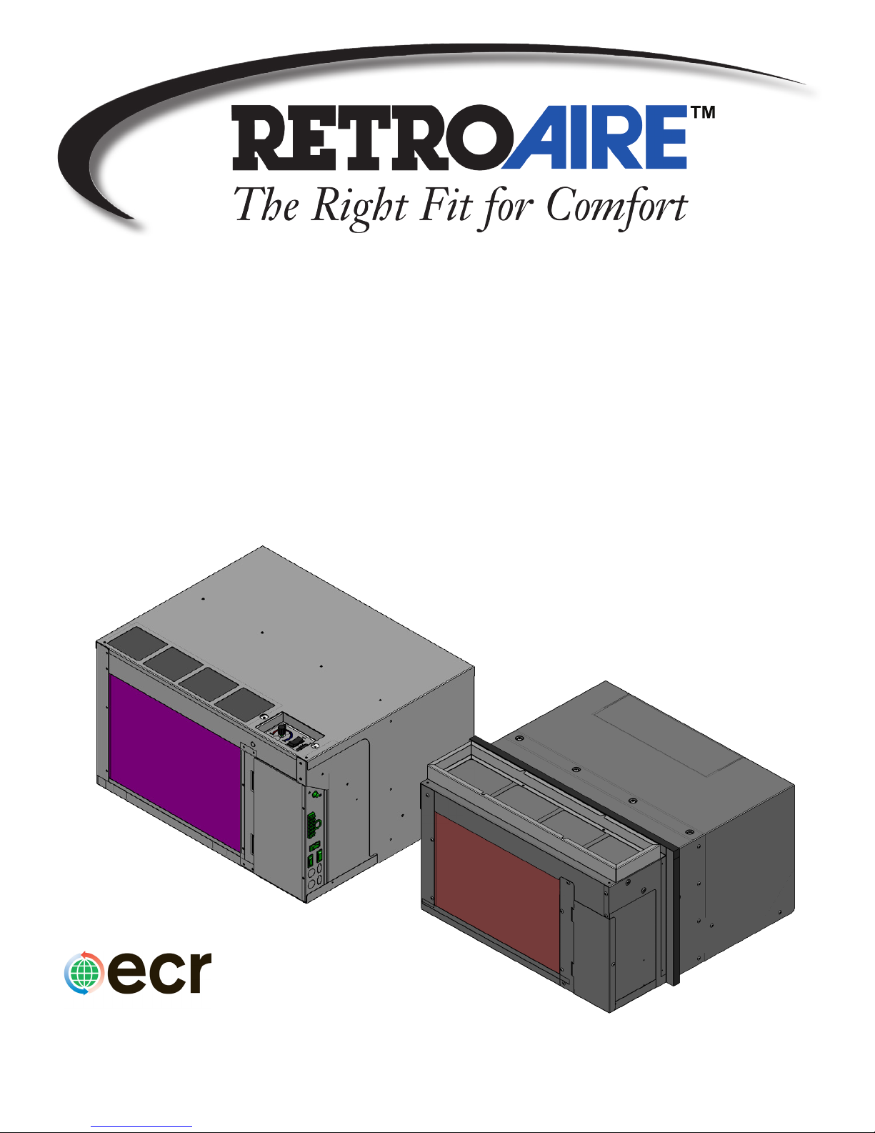
R40C/R41C
Packaged Terminal Air Conditioner (PTAC)
Installation, Operation &
Maintenance Manual
Replacement for:
Fedders Model CMEA packaged Terminal Unit
R40C
ECR International, Inc.
2201 Dwyer Avenue • Utica, New York 13501
Ph: 800.325.5279 • Web: retroaire.com
R41C
P/N 240010598 Rev. A [05/12/2014]
Page 2
TABLE OF CONTENTS
Receiving Information ....................................................................................................3
Important Safety Information .........................................................................................4
R40C - Dimensional/Physical Data ...................................................................................5
R41C - Dimensional/Physical Data ...................................................................................8
General Product Information ......................................................................................... 10
Features ..................................................................................................................... 11
Installation Preparation ................................................................................................ 12
Installation ................................................................................................................. 13
R40C - Bafe Installation ............................................................................................. 14
R41C - Bafe Installation ............................................................................................. 15
Sequence of Operation ................................................................................................. 16
Final Inspection & Start-up ........................................................................................... 18
Maintenance ............................................................................................................... 24
Troubleshooting .......................................................................................................... 27
R40C - Performance Data ............................................................................................. 28
R41C - Performance Data ............................................................................................. 29
Warranty .................................................................................................................... 31
AHRI Certied ™ is a
trademark of the Air-
Conditioning, Heating
and Refrigeration
Institute. These units
are tested and rated in
accordance with: AHRI
Standards 310/380
UL-484
Information and specications outlined in this manual in effect at the
time of printing of this manual. ECR International reserves the right to
discontinue, change specications or system design at any time without
notice and without incurring any obligation, whatsoever.
The Right Fit for Comfort 2
P/N 240010598, Rev. A [05/12/2014]
Page 3

RECEIVING INFORMATION
Shipping damage MUST be reported to the carrier IMMEDIATELY.
Examine exterior.
Remove cover and examine compressor and piping for signs of damage.
Inspection
Check shipment against bill of lading.
Verify equipment received as ordered.
Verify unit:
• Unit size and type correct per submittal sheet and
job requirements?
• Louver color correct, if special color specied?
• Voltage correct?
• Electric heat correct capacity, if used?
Inspect each component for damage. Concealed
damage must be reported to carrier within 15 days
of receipt of shipment.
Carrier must make proper notation on delivery
receipt of all damage identied and complete carrier
inspection report.
Purchaser must notify Manufacturer’s Service
department of all damage and is responsible for ling
any necessary claims with carrier.
General Information
Installation shall be completed by qualied agency.
this manual for future reference.
Installer, review this manual to verify unit has been
installed correctly. Run unit for one complete cycle to
verify proper function.
To obtain technical service or warranty assistance
during or after installation, contact your local
representative.
When calling for assistance, please have following
information ready:
Model Number_________________________
Serial Number_________________________
Date of installation______________________
Retain
Customer Service : (800) 228-9364
3 Made in USA
P/N 240010598, Rev. A [05/12/2014]
Page 4
IMPORTANT SAFETY INFORMATION
All eld wiring shall conform to requirements of authority
having jurisdiction or in absence of such requirements:
• United States - National Electrical Code, ANSI/NFPA
70
• Canada - CSA C22.1 Canadian Electrical Code Part 1.
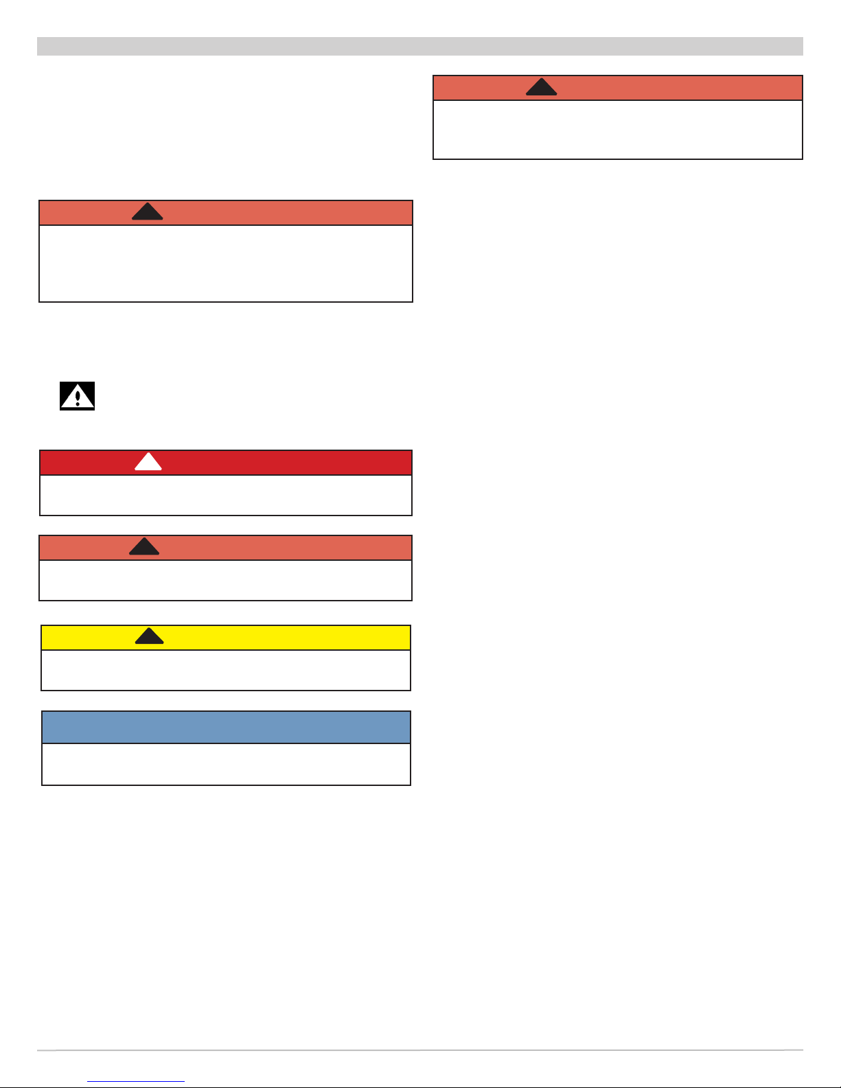
!
WARNING
Fire, and electrical shock hazard. Improper
installation could result in death or serious injury.
Read this manual and understand all requirements
before beginning installation.
Become Familiar With Symbols
Identifying Potential Hazards.
!
DANGER
Indicates a hazardous situation which, if not
avoided, WILL result in death or serious injury.
!
WARNING
Tampering with PTAC/PTHP is dangerous and could
result in death or serious injury. Do not modify or
change this unit.
Safety Information
• Installation by qualied personnel.
• Turn off electrical supply before servicing unit.
• Inspect all parts for damage prior to installation and
start-up.
• Do not use unit if it has damaged wiring, is not
working properly, or has been damaged or dropped.
• Connect to properly grounded electrical supply with
proper voltage as stated on rating plate.
• Have proper over current protection (i.e. time delay
fuse/HACR Breaker) as listed on Rating Plate.
• Connect unit to properly grounded electrical supply.
Do not fail to properly ground this unit.
!
WARNING
Indicates a hazardous situation which, if not
avoided, could result in death or serious injury.
!
CAUTION
Indicates a hazardous situation which, if not
avoided, could result in minor or moderate injury.
NOTICE
Indicates information which should be followed to
ensure proper installation and operation.
The Right Fit for Comfort 4
P/N 240010598, Rev. A [05/12/2014]
Page 5
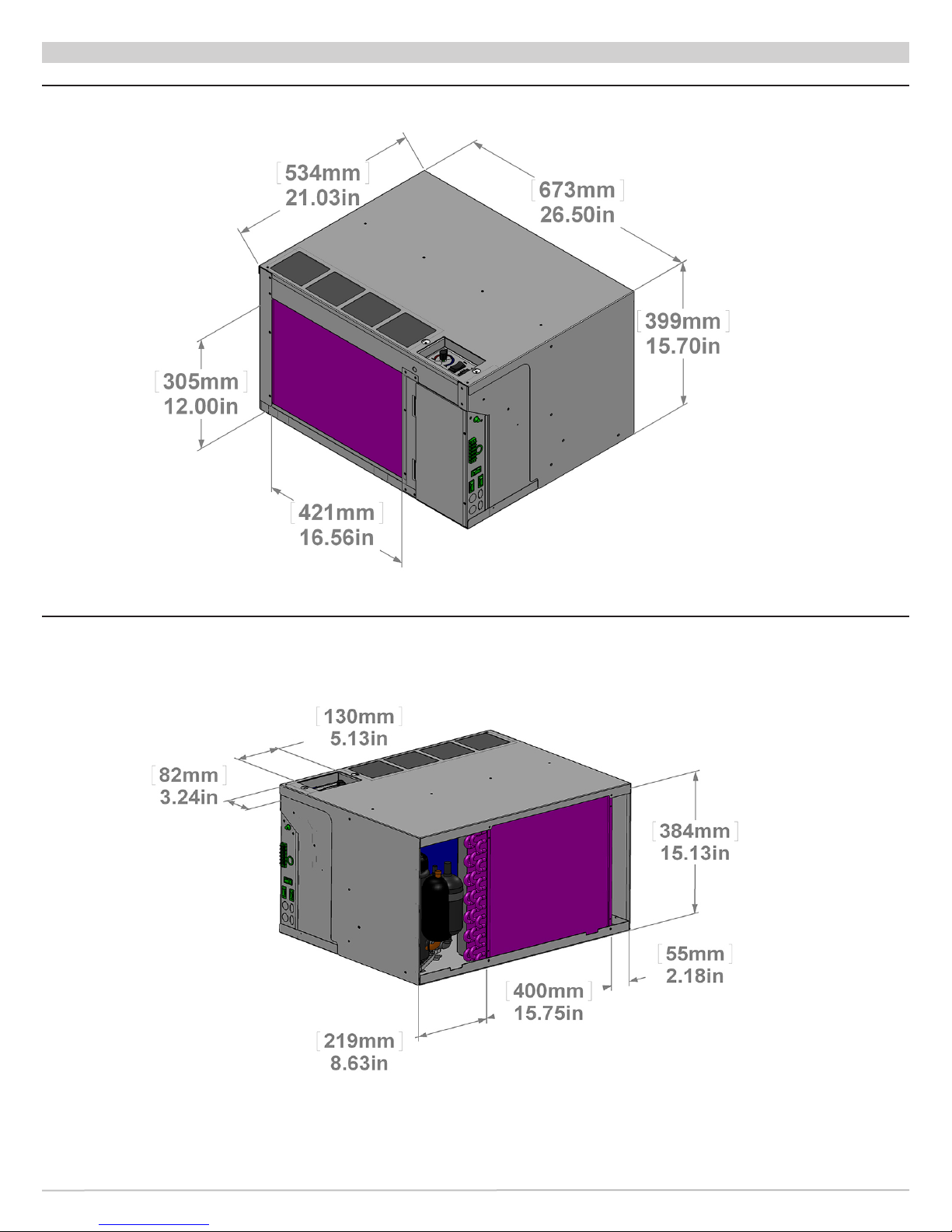
R40C - DIMENSIONAL/PHYSICAL DATA
Figure 1 R40C Dimensions - Inches (mm) Front View
Figure 2 R40C Dimensions - Inches (mm) Rear View
5 Made in USA
P/N 240010598, Rev. A [05/12/2014]
Page 6
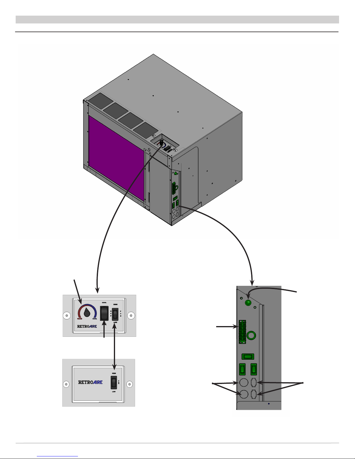
Figure 3 R40C Chassis
R40C - DIMENSIONAL/PHYSICAL DATA
Thermostat
Unit Mount
System
Switch
(SS)
Fan Speed
Switch
(FSS)
Remote Mount
The Right Fit for Comfort 6
5-POS
Terminal
Block
Optional
Knockouts
High Pressure
Switch (HPS)
reset
Optional
Knockouts
P/N 240010598, Rev. A [05/12/2014]
Page 7
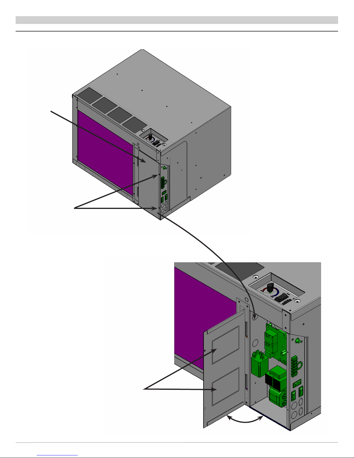
R40C - DIMENSIONAL/PHYSICAL DATA
Figure 4 R40C Chassis Electrical Box
Rating Plate
Remove
Screws to
Open Door
Electrical
Diagram
Open/Close
7 Made in USA
P/N 240010598, Rev. A [05/12/2014]
Page 8
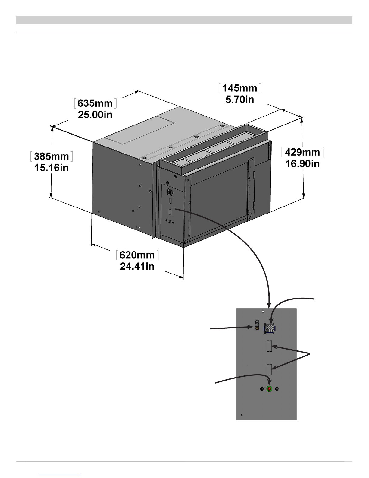
R41C - DIMENSIONAL/PHYSICAL DATA
Figure 5 R41C Dimensions - Inches (mm) Front View
The Right Fit for Comfort 8
12 Position
Molex
Ground
Terminal
Block
Knockouts
for Optional
Switches
High Pressure
Switch (HPS)
reset
P/N 240010598, Rev. A [05/12/2014]
Page 9
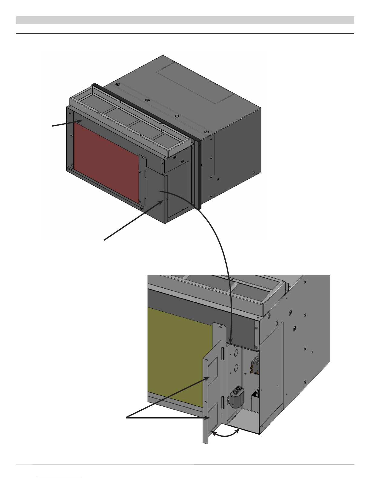
R41C - DIMENSIONAL/PHYSICAL DATA
Figure 6 R41C Chassis Electrical Box
Rating Plate
Remove
Screw to
Open Door
Electrical
Diagram
Open/Close
9 Made in USA
P/N 240010598, Rev. A [05/12/2014]
Page 10

GENERAL PRODUCT INFORMATION
Product Description
• Available in straight cooling (PTAC).
• Use R-410A refrigerant.
• Include high-efciency rotary compressors, protected
by a 5-year warranty.
• Include enhanced high-efciency heat exchangers.
• Offer two fan speeds.
• Incorporate positive condensate re-evaporation to
improve efciency.
• Have optional motorized fresh-air feature with positive
pressure seal.
• PTACunits are available in nominal sizes of 9,000 Btuh,
(2.6kW) 12,000 Btuh (3.5kW) or 15,000 Btuh (4.4kW)
18,000 Btuh (5.3kW).
• Energy Efciency Rating (EER) as high as 9.
Standard Controls And Components
– Construction
• 20-gauge galvanized steel construction of chassis.
• Condenser bafe options to accommodate extended
wall sleeve applications.
• Powder-coated condenser and evaporator drain pan.
• Foam strip seal for supply air duct.
• Weather strip insulation.
– Air Systems
• Thermally-protected PSC type motors.
• Air-stream surfaces insulated with 1/4" ber-glass or
1/8" (3.2 mm) Volara™.
• Forward-curved type indoor fan, directly mounted to
motor shaft.
• Unit mount controls include eld selection switch
to control indoor fan by cycling with compressor
operation or continuously with the unit.
– Condensate Removal
• Outdoor fan incorporates condensate slinger ring.
Condensate is thrown onto coil, where it evaporates,
improving system performance.
• Thermostatic drain pan valve for condensate
elimination when outdoor temperature drops below
60°F (15°C), heat pump units only.
– Controls
• Unit-mounted operating controls include thermostat,
fan speed control, heat/cool switch, fan cycle switch,
fresh air switch, if equipped.
• Ability to utilize 1-stage or 2-stage thermostat. 2
stage thermostat is capable of activating emergency
heat if auxiliary heat source is available.
• Low ambient protection — see "Microprocessor
control board" for details.
• Ability to control normally-open or normally-closed
motor valve switch, available on hydronic heat units
only. Order valve controls for 24V or line voltage.
The Right Fit for Comfort 10
• All hydronic heat units include molex plugs for
connection of hydronic valve motor.
• Remote mount controls include fan speed control and
fresh air switch, if equipped.
• All units are equipped with manual reset high
pressure switch which prevents abnormal high
pressure operation, increasing compressor reliability.
– Microprocessor Control Board
• Universal control board is used in straight cooling,
electric resistance heat, hydronic heat, or cooling/
heat pump applications.
• Random start timer prevents multiple units from
simultaneous startups after power interruption or on
initial power-up.
• Fan purge — fan remains on for 60 seconds after
heat/cool is satised.
• Anti-short-cycle compressor protection prevents the
compressor from rapid cycling, increases compressor
reliability.
• Freeze-protection prevents evaporator coil freeze up,
improving compressor reliability.
• Low ambient lockout prevents compressor operation
in outdoor temperatures less than 40°F (4.4°C).
PTHP units supplied with unit-mounted control,
Control causes automatic changeover to auxiliary
heat, if installed.
• Test operation — all timers are temporarily
suppressed to allow ease of testing or
troubleshooting.
• Control board LED provides self-diagnostic
troubleshooting codes, see "Sequence of operation."
Field-Installed Accessories
• Hydronic heat — coil assembly is shipped loose for
eld installation.
• Remote wall thermostat — digital 1-stage or 2-stage
available.
• Wall sleeves, louvers, and cabinets
• Aquastat - delays fan start-up until coil reaches
100°F (38°C) to eliminate "cold" blow condition.
• Hydronic control valve , Water 2 way & 3 way
• Hydronic control valve, Steam 2 way
• Hydronic Isolation valve, 1/2 in Sweat Connection.
Indoor Coil Freeze Protection (Standard)
Prevents indoor coil from freeze up in cooling mode.
• Indoor coil freeze up can occur due to a dirty air lter,
restricted or poor air ow, low refrigerant charge or low
room or outdoor temperatures.
• This can cause compressor damage.
• Should freeze condition be detected, compressor and
outdoor fan switch off for minimum of three minutes
until freeze condition is satised.
• During this time the indoor fan continues to run to aid
in defrost process.
P/N 240010598, Rev. A [05/12/2014]
Page 11

FEATURES
Condensate Removal (Standard)
RetroAire replacement unit, cooling operation, is designed
to eliminate condensate by slinging it onto outdoor coil.
• Condensate drains through the bulkhead to the area
near the outdoor fan.
• Unit as part of normal operation produces condensate
and collects it in the unit's base pan. It is picked up
there by the outdoor fan slinger ring and deposited onto
the condenser coil. This improves the unit’s efciency
by maintaining reduced refrigeration system pressures.
• Base pan has overow notches. If too much condensate
is produced notches allow condensate to ow out of the
base pan and into the wall sleeve out of the building.
Random Start Feature (Standard)
Random start feature is initiated on initial power-up or
after a power interruption.
• Controller adds a random time delay (from 5–120
seconds) on start-up, preventing compressor from
starting.
• This staggers the start of multiple units in a single
facility, preventing a large surge if all units started at
the same time.
Anti-Short Cycle Timer (Standard)
Microprocessor control uses this timing to prevent
compressor short-cycling.
• When the compressor cycles off on heating or cooling
call, controller starts a 180-second timer.
• Compressor is not allowed to start until this time has
elapsed.
• On initial power-up or after a power failure, this timing
occurs after the random start timing.
Power Cord With Integral Safety Protection
(Standard)
All PTAC/PTHP units rated 250V or less are equipped with
power cord with integral safety protection as standard.
• Providing personal shock protection as well as arcing
and re prevention. Device is designed to sense any
damage in line cord and disconnect power before a re
can occur.
• Tested in accordance with Underwriters Laboratories,
cord set offers a unique “passive” operation, meaning
unit does not require resetting if main power is
interrupted.
Hydronic Heating (Optional)
Hydronic heat package may be selected in lieu of electric
heat. Heating operation is same as that of units with
electric heat.
Aquastat Connection (Optional)
All replacement PTAC/PTHP's with hydronic heat are
supplied with standard line volt Aquastat connection. Field
installed Aquastat delays fan operation until hydronic coil
reaches temperature of 100°F (38°C).
Motorized Fresh Air Damper (Optional)
Motorized fresh air damper allows fresh air into the space
to be conditioned. When the Fresh Air switch is in "YES"
position, damper door is open and allows fresh air into
the space. This is only available when the indoor fan is
on. When damper door switch is in the "NO" position, the
damper door is closed and does not allow air in the space.
Optional Wall-Mounted Thermostats
PTAC compatible thermostats.
• Manufacture offers single stage, cool/heat, thermostat
that can be used in all RetroAire cooling, heating or
heat pump applications.
• Thermostat has adjustable setpoint range of between
45°F (7°C) and 90°F (32°C).
• For heat pumps manufacture offers a 2 stage heat/cool
thermostat which allows for emergency heat.
Selecting A Thermostat
When selecting a thermostat for the PTACchoose a single
stage heat/cool, 24V thermostat.
Straight cooling with electric heat or hydronic heat (R10C
— PTAC's) oling/electric heat system. Thermostat should
have “R”, “Y”, “ W”, "C" and “G” terminals.
Heat Pump With Electric Heat (R__H - PTHPS)
Select a thermostat compatible with cooling/single-stage
heat/heat pump system.
Thermostat should have "R", "Y", "O" and "G" terminals.
RetroAire units are single stage heating only.
Electric heat and heat pump will not operate
simultaneously.
11 Made in USA
P/N 240010598, Rev. A [05/12/2014]
Page 12
INSTALLATION PREPARATION
!
DANGER
Electrical shock hazard — Verify power to existing
unit is disconnected before removing. Failure to do
so will result in death or serious injury.
!
CAUTION
Moving parts can cause personal injury. Avoid
contact with moving parts when testing or servicing
the unit. Failure to follow these instructions could
result in minor or moderate injury.
Verify existing wall sleeve/enclosure:
1.
RetroAire PTAC/PTHP's are to be used with metal wall
sleeves.
2.
Existing front panels must be secured by screws that
prevent contact with all parts.
3.
Minor dimensions of openings must not exceed ½ inch
(12.5mm).
4.
Indoor air discharge grill must have dimensions not
less than 26” x 4”. Grill must separate top surface of
chassis from top surface of discharge grill by minimum
of 1 in (25.4mm).
5.
For all models, outdoor openings must prevent contact
of all moving parts by means of louvers or grills, with
minor dimension not exceeding 1 in (25.4mm).
Electrical Power Connection
All wiring shall conform to requirements of authority
having jurisdiction or in absence of such requirements:
• United States
National Electrical Code, ANSI/NFPA 70
UL 1995 4th Addition.
• Canada
CSA C22.1 Canadian Electrical Code Part 1.
Installer is responsible for ensuring units are installed in
accordance with all applicable national and local codes.
UNITS RATED 208/230V — RetroAire unit is wired for 230v
primary voltage from manufacture.
Transformer must be rewired by installer if job site voltage
is 208V. Change transformer tap from orange to red. See
wiring diagram for details.
1.
Verify RetroAire unit rating plate for circuit ampacity
and required breaker or fuse size.
2.
Verify existing breaker or fuse is correct size.
A. Replace breaker or fuse if incorrectly sized.
B. Breakers must be type HACR only.
3.
Cord connected units — verify wall outlet is correct
rating. Outlet's blade conguration must match that of
cord supplied with RetroAire unit.
4.
Hard-wired units — verify power wiring is correctly
sized. Inspect existing wiring for deciencies, such as
cuts or frayed wires. Replace any decient wiring if
found.
5.
Each unit must have separate branch circuit protected
by fuse or breaker. Refer to unit rating plate for proper
wire and breaker or fuse size. Use of extension cords is
prohibited.
6.
DO NOT connect RetroAire unit to circuit with
incorrectly sized overcurrent protection device.
7.
All cord-connected 265-volt units must be plugged into
receptacles within unit subbase or chassis.
8.
Open power supply disconnect switch. Secure in open
position during installation. Attach sign stating, "DO
NOT TURN ON."
9.
On a plug and receptacle connection, unplug existing
unit at the wall outlet. DO NOT plug in the new unit
until installation is complete and start-up checklist has
been completed.
Remove Old Chassis
1.
Disconnect power or unplug cord before proceeding.
2.
Remove front of the existing room enclosure to expose
old chassis.
3.
Loosen any tie-down bolts or screws. Remove old
chassis.
NOTICE
Dispose of old chassis following existing state and
federal regulations.
4.
Inspect wall sleeve/cabinet for any rust, holes, or
damage.
A. Clean wall sleeve of any dirt.
B. Repair any damage.
C. Ensure proper drainage of condensate or rainwater
to exterior of building.
5.
Remove or repair old weather seals. Note location for
installation of any new seals.
6.
Check wall sleeve/cabinet to ensure all drain holes are
open and:
A. Wall sleeve/enclosure is level left to right
B. Back is pitched to outside by ½ in (12.5mm)
maximum.
7.
Before installing new chassis, inspect outdoor louver
for minimum free area of 70% and remove any
obstructions. Obstructions restrict air ow over
condenser coil and may cause damage to the chassis.
8.
Follow the installation instructions on the following
pages.
9.
DO NOT connect power to the unit or plug in the cord
until instructions in this manual have been completed.
The Right Fit for Comfort 12
P/N 240010598, Rev. A [05/12/2014]
Page 13

INSTALLATION
Installation
1.
Verify existing wall thickness. Distance from
condenser coil to outdoor louver varies with wall sleeve
depth. Units shipped with factory installed bafes.
Manufacturer offers alternate air bafe kits for unique
applications. Wall sleeve depth is required when
ordering to ensure proper bafe size.
2.
Connecting optional hydronic coil controls. If
hydronic heat option has been ordered, eld install
the hydronic coil on the new unit. Coil with old unit
can be located in subbase, under chassis in a special
attachment, or above chassis in a special attachment.
It is necessary to know where the coil is to be located
and physical size of the coil so the new coil can be
veried if ordered for replacement. The new coil
should be installed in the same manner as the coil it is
replacing. Hydronic coils are not factory installed and
need to be ordered.
• Remove 2-position connector assembly from kit
bag supplied with unit. This will have 2 yellow wires
attached.
• Splice 2 yellow wires to valve motor using 2 - crimp
popcorn.
• Connect this 2-position connector to 2-position
connection located on bottom of control box panel.
3.
Connecting accessory eld installed Aquastat.
A. Remove black jumper wire located on bottom panel
of control box. This is terminated with 2-position
connector.
B. Cut jumper wire in the middle and splice the
Aquastat to jumper using 2 - crimp popcorns.
C. Place connector back into original location. Refer to
wiring diagram on unit for details.
4.
Install Bafes - Install correct condenser
bafes for proper performance of unit.
See Figures 7 and 8
A. Slide unit back out of wall sleeve.
B. Remove both sets of provided bafes from
accessory bag. Install only one set of left and right
side bafes on the condenser coil.
C. Choose the proper tting bafes for your
application by verifying selected bafes come in
contact with outdoor louver.
D. Verify bafes are directed inward toward center of
coil.
E. Secure bafes tightly into existing holes of
condenser coil using provided screws.
5.
Secure chassis — Verifying all seals are correct size,
located properly, and correct bafes are attached to
condenser coil in proper orientation. Slide unit into
nal position and tighten tie down bolts or screws.
6.
Hard-wired units — Hard wired units follow
instructions on page 10 to verify existing wiring and
over current protection.
A. Remove line cord wires from PTAC/PTHP power
entrance terminals.
B. Route power supply wiring through strain-relief
bushing and connect leads to power entrance
terminals. Secure the strain-relief clamp.
C. If wiring is through conduit insert conduit through
control box knockout and secure in place. DO NOT
turn on power until completing instructions in
"Final Inspection and Startup" page 22.
7.
DO NOT PLUG IN the line cord, if used. Follow
instructions in "Final Inspection and Startup" page 22.
13 Made in USA
P/N 240010598, Rev. A [05/12/2014]
Page 14
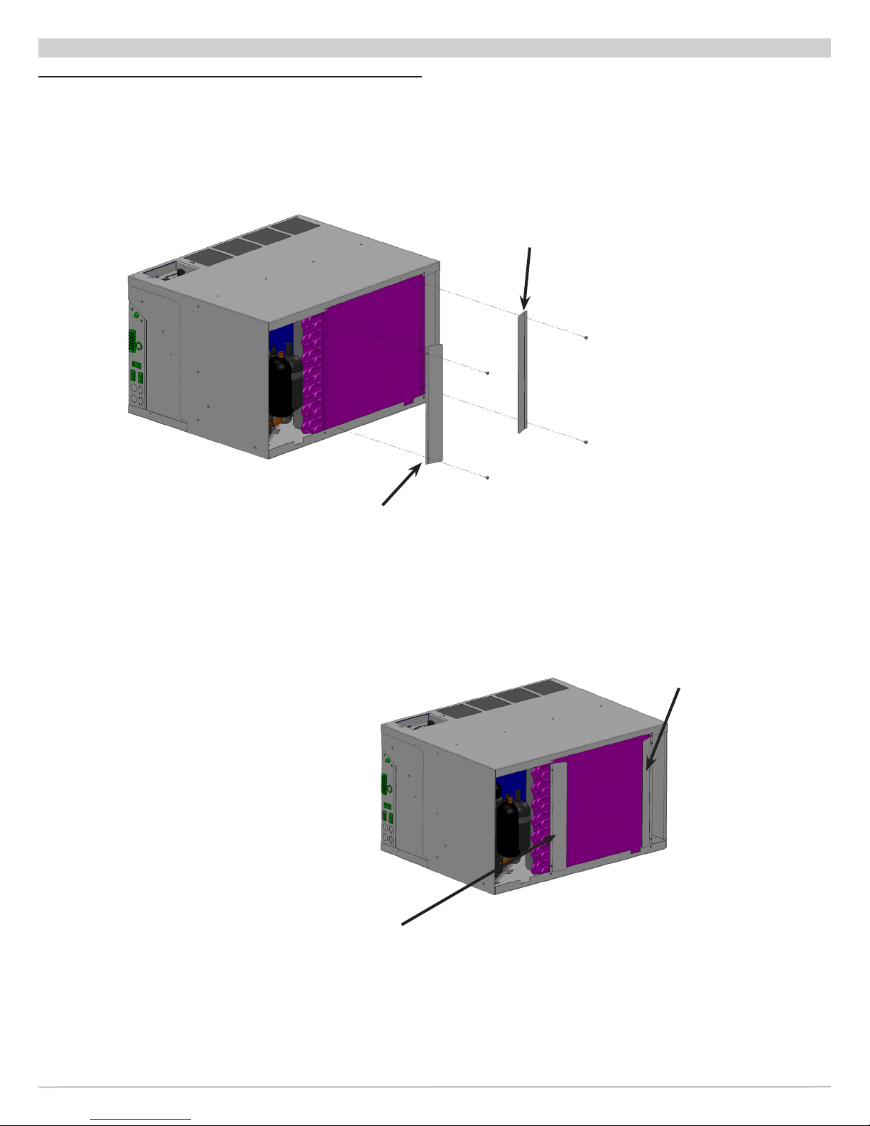
Figure 7 R40C Bafe Options
R40C - BAFFLE INSTALLATION
Standard Bafe
Standard Bafe
Standard Bafe
Standard Bafe
The Right Fit for Comfort 14
P/N 240010598, Rev. A [05/12/2014]
Page 15
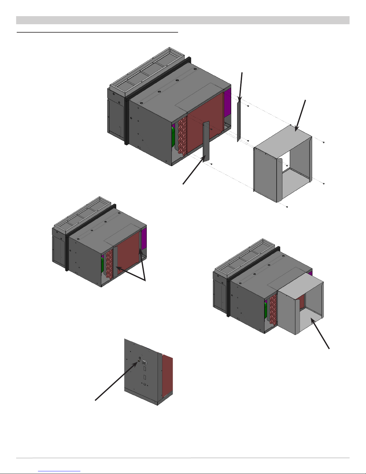
R41C - BAFFLE INSTALLATION
Figure 8 R41C Bafe Options and Field Ground
Connection
Standard Bafe
Standard Bafe
Optional Bafe
For Deeper Wall
Sleeves
Field GRND Connected
to Ground Terminal
Standard Bafe
Optional Bafe
For Deeper Wall
Sleeves
15 Made in USA
P/N 240010598, Rev. A [05/12/2014]
Page 16
SEQUENCE OF OPERATION
Sequence of Operation
• R_ _C units are straight cool, single stage air
conditioners available with electric or hydronic heat.
General
Microprocessor controlled unit. Thermostat and control
connections are made to the control board.
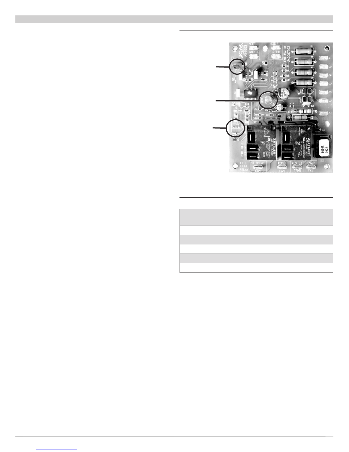
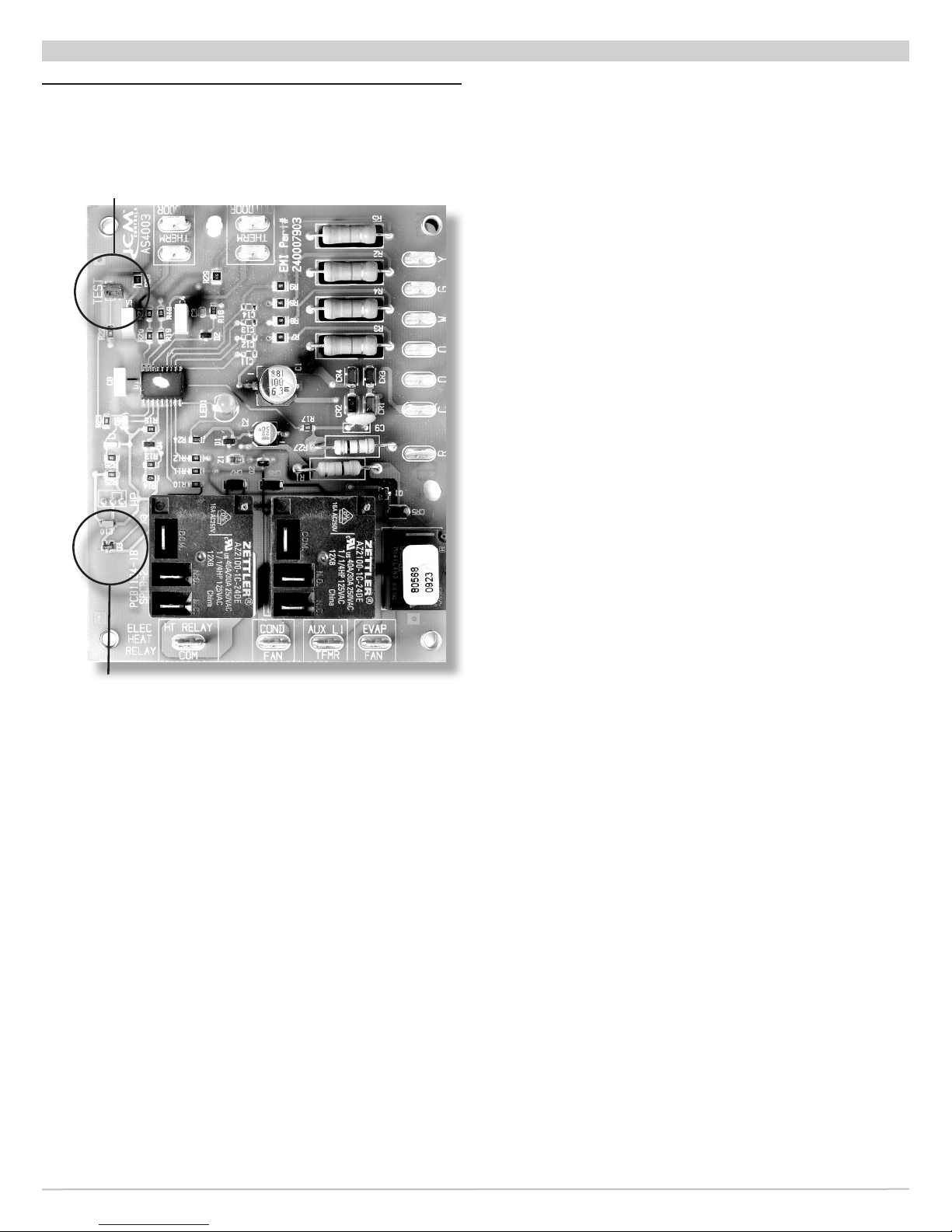
Two conguration jumpers are located on the board. See
Figure 9.
• Straight Cool units R_ _C, locate jumper on outside two
pins.
Second conguration jumper “TEST” allows for control’s
internal timers to be by-passed for test purposes. Placing
jumper on two pins enables test mode.
Status LED (Light Emitting Diode), LED1 is located
on center of board. Series of blinks communicates
board status. Between blink sequence is separation of
approximately 2 seconds. See Table 1.
Initial Power-Up or Power Restoration
• When power is applied to the unit, either for the rst
time or after a power failure, board initializes itself.
• During initialization, LED1 is lit for approximately 5
seconds.
• Following initialization, a random start timer is
initiated. Timer adds randomly selected 5-120
seconds to start-up sequence, reducing possibility of
multiple units starting at same time.
• Once random start timer has expired, 180 second
Anti-Short Cycle Timer is initiated and Processor
Board Trouble Code LED is set to blink a 2 ash code.
Timer prevents compressor from rapid cycling.
• After Anti-Short Cycle Timer expires, Processor Board
Trouble Code LED is set to blink 1 blink Trouble Code,
indicating normal operation.
Figure 9 - Control Board
Conguration
Conguration
TEST
Jumper
LED
Indicator
Light
Heat
Pump
Jumper
Table 1 - Status Codes
Trouble Code
(Blinks)
1
2
3
4
5
Anti-Short Cycle Timer Active
Outdoor Coil Freeze Protection
Indoor Coil Freeze Protection
Simultaneous “Y” and “W” Call
Status
Normal Operation
R_ _C ; Cooling Operation
Unit Mount Controls
• With System Switch [SS] set to “Cool”, and Fan Cycle
Switch [FCS] set to “On” (Continuous Fan Operation),
indoor fan motor starts.
• If Fan Cycle Switch [FCS] is set to “Off” (Cycling Fan
Operation), indoor fan motor starts with call for cooling
from internal thermostat [T’stat].
• If equipped with Motorized Fresh Air Damper, and is
active with Fresh Air Switch [FAS], damper will open
with call for the indoor fan.
• If room temperature is below thermostat setting fan
operation continues as noted.
• If room temperature is above thermostat setting,
reversing valve is energized. Compressor and outdoor
fan start provided Anti-Short Cycle Timer has timed out
from initial power-up, power restoration or previous
compressor on cycle. Operation will continue until room
temperature satises the thermostat.
The Right Fit for Comfort 16
P/N 240010598, Rev. A [05/12/2014]
Page 17

SEQUENCE OF OPERATION
• Once room temperature falls below set point by 3º F (2º
C) compressor, outdoor fan motor and reversing valve
will de-energize.
• If FCS is set to “Off”, indoor fan continues to operate for
60 seconds after compressor stops.
• If FCS is set to “On”, indoor fan continues to operate.
• Anti-Short Cycle Timer is initiated, prohibiting
compressor operation for 180 seconds. Processor
Board Trouble Code LED ashes 3 blink Trouble
Code, indicating auxiliary heat operation.
• Heating operation with auxiliary heat continues
until outdoor coil sensor reaches 50º F (10º C).
A.1 “Electric Heat”
• As soon as the compressor is de-energized, Anti-Short
Cycle Timer is initialized and prevents compressor from
starting again for another 180 seconds.
• While Anti-Short Cycle Timer is active, Processor Board
Trouble Code LED is set to blink a 2 ash code.
• After Anti-Short Cycle Timer expires, Processor Board
Trouble Code LED is set to blink 1 blink Trouble Code,
indicating normal operation.
NOTE:
Remote-Mount Cooling Operation depends on
features of wall-mounted thermostat. By default fan will
cycle with call for cooling.
For thermostats with AUTO / ON fan switch, fan will run
continuously if this is “ON” (Continuous Fan Operation).
Fan cycles with call for cooling if this is set to “AUTO”
(Cycling Fan Operation).
In cooling, units will not start if indoor air temperature is
60º F (15.5º C) or below or outdoor temperature is below
40º F (4.5º C).
R_ _C Heating Operation
• With System Switch [SS] set to “Heat”, and Fan Cycle
Switch [FCS] set to “On” (Continuous Fan Operation),
indoor fan motor will start.
• If Fan Cycle Switch [FCS] is set to “Off” (Cycling Fan
Operation), indoor fan motor will start with call for
heating from the internal thermostat [T’stat].
• If equipped with Motorized Fresh Air Damper, and is
active with Fresh Air Switch [FAS], damper opens with
call for indoor fan.
• If room temperature is above thermostat setting fan
operation continues as noted above.
• If room temperature is below thermostat setting,
action of the unit will depend on outdoor temperature
and freeze sensor status.
NOTE: Remote-Mount Heating Operation depends on
features of wall-mounted thermostat. By default fan will
cycle with call for Heating.
For thermostats with AUTO / ON fan switch, fan runs
continuously if this is “ON” (Continuous Fan Operation).
Fan cycles with call for heating if this is set to “AUTO”
(Cycling Fan Operation).
A. R_ _H; Auxiliary Heating “Electric” or “Hydronic”
• If outdoor coil temperature falls to 25º F (-4º C) or
below for 180 seconds at anytime during heating
call, compressor and outdoor fan motor are deenergized and auxiliary heat is energized.
17 Made in USA
P/N 240010598, Rev. A [05/12/2014]
A. System Switch [SS] set to “Heat”, and Fan
Cycle Switch [FCS] set to “On” (Continuous
Fan Operation), indoor fan motor starts.
B. If Fan Cycle Switch [FCS] is set to “Off”
(Cycling Fan Operation), indoor fan motor
starts with call for heating from internal
thermostat [T’stat].
C. If unit is equipped with Motorized Fresh Air
Damper, and is activated with Fresh Air Switch
[FAS], damper opens with call for indoor fan.
D. If room temperature is above thermostat
setting fan operation continues as noted
above.
E. If room temperature is below thermostat
setting, electric heater is energized until room
temperature satises thermostat.
F. Once room temperature increases above set
point by 3º F (2º C), electric heaters are deenergize.
A.2 “Hydronic Heat”
A. If FCS is set to “On” (Continuous Fan
Operation) and unit has Aquastat, the indoor
fan and fresh air motorized damper operation
are controlled by the Aquastat.
B. If the Aquastat senses temperature of 80 ± 5º
F (26 ± 3º C) or below, the indoor fan shuts
down and the motorized damper closes fresh
air door.
C. With call for heat, signal from processor board
activates water or steam valve.
D. If unit is equipped with a eld installed
Aquastat [AS], the indoor fan start will be
delayed until the hydronic coil reaches 100
± 5 ºF (38 ± 3 ºC). The signal to the water
or steam valve will continue until the room
temperature rises above the set point by 3 ºF
(2 ºC). If the FCS is set to “Off”, the indoor
fan will continue to operate for 60 seconds or
until the hydronic coil temperature as sensed
by the Aquastat reaches 80 ± 5 ºF (26 ± 3
ºC), whichever occurs rst. If the FCS is set
to “On”, the indoor fan will de-energize if the
Aquastat senses a temperature of 80 ± 5 ºF
(26 ± 3 ºC) or below.
A.3 “Remote Wall Thermostat Controls”
Cooling and Heating operates identical to unit
mount controls.
See remote controls manual for control details.
Remote units do not use a system switch, or FCS.
Page 18
FINAL INSPECTION & START-UP
Before Operating The Unit
1.
Install unit per the instructions outlined in this manual
and all applicable local and national codes.
2.
Verify electrical supply matches electrical requirements
of the unit, and unit is properly grounded.
3.
Examine control box. Verify all wire connections are
secure, and control board jumpers are in proper
positions.
4.
Verify chassis is properly tted to wall sleeve and
securely mounted to surrounding framing.
5.
Verify chassis is level: Pour water into drain pan.
Verify it ows through the drain hoses to condenser
side of unit.
6.
Verify indoor blower wheels and outdoor fan blades are
secured to their motor shafts, and rotate freely.
7.
Verify all sheet metal panels are in place and secure.
8.
Attach front panel to the existing cabinet enclosure.
9.
Verify nothing interferes with room discharge air or
return air of units.
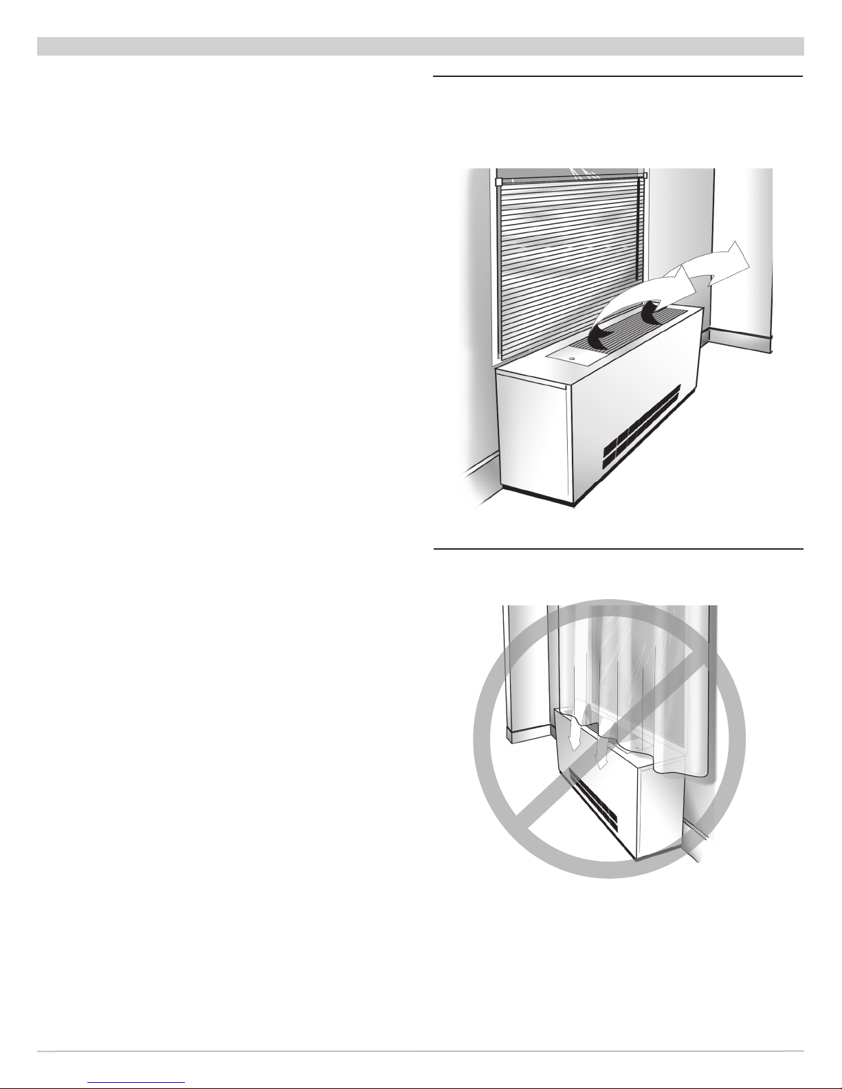
Examples:
Check for curtains or drapes that obstruct air ow. See
Figure 10 and Figure 11.
Check for plush carpeting that can obstruct return air.
These types of obstructions can cause serious damage
to the chassis.
Figure 10 - Proper Air Flow Diagram
Figure 11 - Restricted Air Flow Diagram
Any obstruction of supply air, including use of deector
bafes, may cause condensate to form on louver or
cabinet. See Figure 11.
For optimum performance of your PTAC/PTHP, avoid
restricting the air ow. Position of curtains or drapes
over supply air grille may cause air to recirculate without
cooling the room. Unit will short cycle and may cause
premature compressor failure. See Figure 11.
The Right Fit for Comfort 18
P/N 240010598, Rev. A [05/12/2014]
Page 19
FINAL INSPECTION & START-UP
Electrical Connections
Installation and wiring shall be in accordance with
requirements of authority having jurisdiction In absence of
such requirements refer to:
• USA- National Electrical Code, ANSI/NFPA 70.
• Canada - Canadian Electrical Code, Part I, CSA C22.1:
Safety Standard for Electrical Installations.
Units Rated 208/230V:
• RetroAire unit is wired for 230V primary voltage from
manufacturer.
• Transformer must be rewired by installer if job site
voltage is 208V.
• Change transformer tap from orange to red. See wiring
diagram for details. See Figure 4 page 6 and Figure 6
page 9 for location of wiring diagram.
Setting Control Board Jumpers
Control board has two sets of factory installed jumper
pins: HP jumper and TEST jumper.
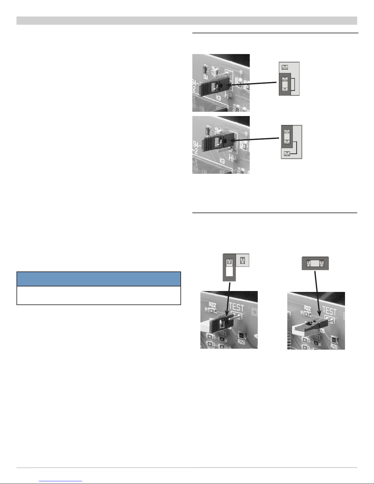
HP Jumper — selects heat pump or straight cooling.
Pins determine whether unit operates as straight cooling or
as heat pump. See Figures 12 and 13.
• Jumper right pin to center pin for heat pump operation.
• Jumper left pin to center pin for straight cooling
operation.
Figure 12 - HP Jumper (selects heat pump or
straight cooling)
Heat Pump Mode
(Jumper center
& Bottom pins)
HP
Straight
Cool Mode
(Jumper center
HP
& Top pins)
Figure 13 - TEST jumper (selects normal or
test mode)
Normal operation
(pins not jumped)
Test mode
(pins jumped)
TEST Jumper
— selects normal or test mode
NOTICE
Do not leave unit operating with TEST jumper in
TEST position.
• Jumper is for testing only. See Figure 13 and 14.
• When jumper pins are jumped together, all timers are
eliminated (example — anti-short cycle, purge, etc.).
• May be used for eld testing. Units are factory set with
jumper on only one pin (normal operation position).
19 Made in USA
P/N 240010598, Rev. A [05/12/2014]
Page 20
FINAL INSPECTION & START-UP
Figure 14 TEST jumper (selects normal or
test mode)
TEST JUMPER
HEAT PUMP
JUMPER
The Right Fit for Comfort 20
P/N 240010598, Rev. A [05/12/2014]
Page 21
FINAL INSPECTION & START-UP
Start Up
1.
Verify unit is secure and level.
2.
Heat pump units only — Verify thermostatic drain pan
valve is operating correctly. Valve should be closed if
temperature is above 60° F and open if below 60°F.
3.
Test fresh air damper, if equipped, by setting damper
door switch to "YES". Verify damper opens and allows
fresh air to be moved into the space. Set damper door
switch to "NO". Verify ow of air into the space has
stopped. Fresh air is only available when indoor fan is
operating.
4.
Verify HP jumper is set correctly for unit type, cooling
only or heat pump. See Figure 12, page 19.
5.
Set TEST jumper to test mode, this disables time
delays, including anti-short-cycle and purge times. See
Figure 13, page 19.
6.
Verify unit is wired correctly, including requirements on
page 16.
7.
Connect Electric power to unit.
8.
Turn unit on. Verify proper operation.
9.
Verify condensate removal:
A. Pour water into base pan.
B. Place unit in cooling mode, with condenser fan
operating, verify water is picked up by slinger ring
and thrown onto outdoor coil.
Compressor will not start until anti-short time period has
elapsed.
On power-up, there are delays for control board
initialization and random start timing. See Sequence of
Operation Section, page 16.
Unit Mounted Thermostat
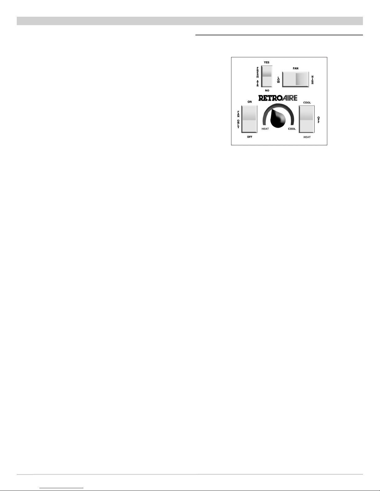
Figure 15 Typical Representation - Unit
Mount Control
THERMOSTAT KNOB
Do not rotate thermostat knob back and forth from heating
to cooling.
This causes compressor to cycle on and off rapidly and will
cause damage to the compressor.
Allow compressor to remain off for at least three minutes
prior to restarting the unit.
Remote Mounted Thermostat
1.
Use thermostat to place PTAC/PTHP in COOL, HEAT, or
OFF position. Test operation in all positions.
2.
If thermostat is tted with fan switch, set as desired
places the fan in either ON, OFF, or AUTO. Test
operation in all positions.
3.
Check thermostat calibration for both heating and
cooling operation.
1.
Use system switch to place PTAC/PTHP in COOL,
HEAT, or OFF position. Test operation in all positions.
See Figure 15.
2.
Use fan speed switch to place fan in LOW or HIGH
speed. Test operation in both positions for heating and
cooling. See Figure 15.
3.
Test operation of Fan Cycle switch, toggle switch on
side of control box. Set switch to ON, continuous fan
operation, or AUTO, cycling with thermostat, for both
heating and cooling. Set switch in desired position.
4.
Rotate thermostat knob left to increase setpoint
temperature, or right to decrease.
• Turning unit-mounted thermostat knob to far left
produces the warmest room temperature.
• Turning thermostat knob all the way to the right
produce coolest room temperature.
• Setting can be adjusted for personal comfort. See
Figure 15.
21 Made in USA
P/N 240010598, Rev. A [05/12/2014]
Page 22

FINAL INSPECTION & START-UP
Straight Cooling PTAC's
Important Information
• Room temperature must be above 65°F (18°C) for
compressor to operate in cooling mode on PTAC's with
unit-mounted controllers.
• Room temperature must be below 85°F (29.4°C) to
energize the heater on PTAC's with unit-mounted
controllers.
• Room temperature must be below 85°F (29°C) for
hydronic heater to operate on PTAC's with unitmounted controllers.
Hydronic valve is 24 Vac normally open valve. Should
power be interrupted, valve will default to open
position.
• When unit is rst powered up, high humidity conditions
may cause condensation to form on discharge grill.
Keep doors and windows closed to reduce humidity
allowing condensation to evaporate.
Cooling Cycle
1.
Place thermostat or system switch in COOL position.
2.
Adjust thermostat to cooler temperature until indoor
fan starts running. Compressor and outdoor fan will
turn on and cold air will begin to ow from unit.
Allow unit to continue operating to cool the room and
remove humidity.
3.
After unit starts and space gets cooler, adjust
thermostat to warmer temperature until compressor
cycles off.
4.
If a colder room temperature is desired, adjust
thermostat to cooler temperature setting, turn
compressor and both fans back on.
5.
If a warmer room temperature is desired, adjust
thermostat to warmer temperature setting.
Compressor and outdoor fan stop, indoor fan switches
off after sixty-second purge time has elapsed.
6.
Place thermostat or system switch in OFF position.
All operation will stop.
Heating Cycle — Electric Option
1.
Outdoor fan does not run during heating cycle.
2.
Place thermostat or system switch in HEAT position.
3.
Adjust thermostat for warmer temperature until
indoor fan starts running and electric heater coil starts
emitting heat.
4.
After unit starts running and space gets warmer,
adjust thermostat to cooler temperature until electric
heater turns off.
5.
If warmer room temperature is desired, adjust
thermostat to warmer temperature setting, which will
turn electric heater on.
6.
If cooler room temperature is desired, adjust
thermostat to cooler temperature setting until electric
heater turns off. Indoor fan will switch off after sixtysecond purge time has elapsed.
7.
Place thermostat or system switch in OFF position. All
operation will stop.
The Right Fit for Comfort 22
Heating Cycle — Hydronic Option
Before Starting The unit:
• Verify motor valve is rated for correct voltage.
• Most RetroAire units with unit mount controls will
power a hydronic valve that is the same voltage
as the unit (ex: a unit rated 208/230v will power a
208/230v).
• Switch is provided on control box to change from NO
to NC.
• Verify wiring using wiring diagram, located on the unit,
and voltage application for the specic unit.
• Other valve congurations and voltage options are
available. Consult Technical Service if unit voltage does
not match your valve application.
Starting the unit:
1.
Place thermostat or system switch in HEAT position.
2.
Adjust thermostat to warmer temperature.
3.
A signal from processor board will activate the water or
steam valve.
4.
The motorized valve will open and allow hot water or
steam to run through the coil.
5.
Indoor fans run, blowing air through the hydronic coil
6.
If the unit is equipped with an Aquastat, the indoor fan
and motorized damper operation are delayed until the
hydronic coil reaches 100 ± 5°F (38 ± 3°C).
7.
The signal to water or steam valve continues until
room temperature rises above setpoint by 3°F (2°C).
8.
Once the area gets warmer, adjust thermostat to a
cooler temperature. The hydronic valve closes and
indoor fan switches off after sixty-second purge time
has elapsed.
9.
If warmer room temperature is desired, adjust
thermostat to warmer temperature setting, which
opens the hydronic valve and turns on the indoor fan.
10.
If cooler room temperature is desired, adjust
thermostat to cooler temperature setting. Hydronic
valve closes and indoor fan switches off after sixtysecond purge time has elapsed.
11.
Place thermostat or system switch in OFF position.
All operation stops.
Testing Completion For Cooling-Only PTAC's
Operation testing is now complete.
If TEST jumper was set to test mode verify it is set back to
normal operation. See Figure 10, page 16.
NOTICE
Do not leave unit operating with TEST jumper in
TEST position.
P/N 240010598, Rev. A [05/12/2014]
Page 23

FINAL INSPECTION & START-UP
Auxiliary Heating Operation — Electric Option
Room temperature must be below 85°F(29°C) to energize
heater on PTHP's with unit-mounted controllers.
1.
Place thermostat or system switch in HEAT position.
2.
Adjust thermostat to warmer temperature until indoor
fans start running and electric coil starts emitting heat.
3.
After space gets warmer, adjust thermostat to cooler
temperature until electric heater turns off.
4.
If warmer room temperature is desired, adjust
thermostat to warmer temperature setting, which will
turn electric heater back on.
5.
If cooler room temperature is desired, adjust
thermostat to cooler temperature setting until electric
heater turns off. Indoor fan will switch off after sixtysecond purge time has elapsed.
6.
Place thermostat or system switch in OFF position.
All operation stops.
Electric Heat Models
Manually reset limit switch if the limit switch opens and
de-energizes the electric heat.
To reset switch:
• Turn power off
• Remove control box cover.
• Locate limit switch.
• Push reset button in, located on the face of the switch
23 Made in USA
P/N 240010598, Rev. A [05/12/2014]
Page 24
MAINTENANCE
!
WARNING
Electrical shock hazard. Disconnect power to unit
before servicing or accessing control compartment.
Failure to do follow these instructions could result in
death or serious injury.
NOTICE
Perform regular service and maintenance by
qualied service agency at least once every 12
months to assure safe, trouble free operation and
maximum efciency.
NOTICE
Verify proper operation after servicing.
Maintenance Schedule
Manufacturer recommends performing following
inspections and maintenance on monthly basis. Units
installed in harsh or dirty environments will require more
frequent inspections and maintenance.
Disconnect power to unit and remove necessary access
panels:
☐ Clean or replace indoor air lter.
☐ Inspect chassis interior for rodent or insect infestation.
Clean if necessary.
☐ Clean & ush condensate drain pan and chassis base pan.
☐ If applicable, verify condensate drain is functioning
properly.
☐ Inspect refrigeration tubing, especially braze joints, for
signs of refrigerant leaks (oil residue). Repair if necessary.
☐ Inspect indoor and outdoor coils. Verify dirt or debris
have not collected on ns. Clean if necessary. Take care
not to damage coil ns when cleaning. Use n comb to
straighten any bent ns.
☐ Examine control box. Verify all wire connections are
secure.
☐ Verify indoor blower wheels and outdoor fan blades are
secured to their motor shafts.
☐ Verify dirt or debris have not collected on indoor blower
wheels and outdoor fan blades. Use vacuum and soft
brush to clean if necessary.
☐ Verify any ductwork connected to unit is secure and free
of air leaks.
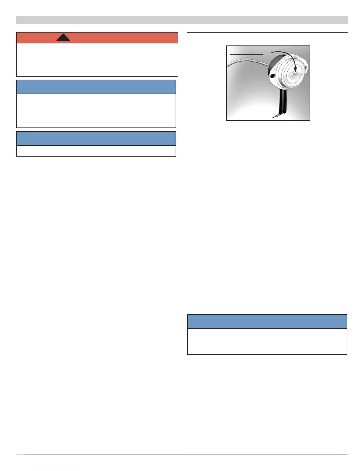
☐ ELECTRIC HEAT MODELS — in event the limit switch
opens and de-energizes the electric heat, limit switch
will need to be manually reset. See Figures 16, 18 and
19.
To reset switch:
• Remove the control box cover.
• Locate the limit switch.
• Push in the reset button on the face of the
switch.
Figure 16 - Manual Reset Limit Switch
Reset Button
*Note:
Button will pop
out when limit
switch opens. Push
in to reset.
Seasonal Start-Up And Maintenance
Beginning of cooling and heating seasons, complete
mechanical check should be performed and maintenance/
inspections performed as described below.
Disconnect power to unit and remove necessary access
panels:
1.
Remove access panel. Visually inspect equipment.
Look for obvious changes in unit such as damaged coils
or evidence of extended wear on any moving parts.
2.
Check for unusual odors or leaks (examples: burnt
motor windings, water, or refrigerant). Verify base pan
is clean.
3.
Clean or replace return air lter as needed. Check lter
at least once month. Some environments may require
more frequent replacement, depending on particulate
in air stream.
4.
Inspect all electrical connections for frayed wires and
poor connections.
5.
Check fan motors and blower assemblies. Verify screws
and motor mounting hardware are tight.
6.
Centrifugal fan blades and blower cage brush and/or
vacuum as necessary.
7.
Inspect both indoor and outdoor coils. Use n comb to
straighten out any damaged ns.
NOTICE
Do not use solvent based cleaner to clean coils,
some solvents will produce noxious odor when unit
is in operation or may deteriorate components.
8.
Look for oil leaks or stains on or around all braze joints
and refrigerant lines. Presence of oil here indicates
potentially serious problem, such as refrigerant leak.
9.
Inspect and clean drain pan and drain line(s). Use of
anti-fungicide tablet to keep condensate system free
from bacterial contaminants is recommended.
10.
Verify unit is level for proper operation. Building and
equipment may settle, causing shift in direction of
condensate ow. Verify weep holes along rear ange of
base pan are free of debris.
The Right Fit for Comfort 24
P/N 240010598, Rev. A [05/12/2014]
Page 25
MAINTENANCE
11.
Air leaks may make the conditioned area
uncomfortably drafty or produce noises. Visually
inspect foam gasket between wall and unit, taking
note of separation between air inlet for condenser
and condenser coil discharge. These two areas must
be sealed off from each other. If you experience poor
cooling operation or erratic operation, check for air
recirculation at condenser coil.
12.
Replace access panels and reconnect electrical power.
Troubleshooting Sensors
1.
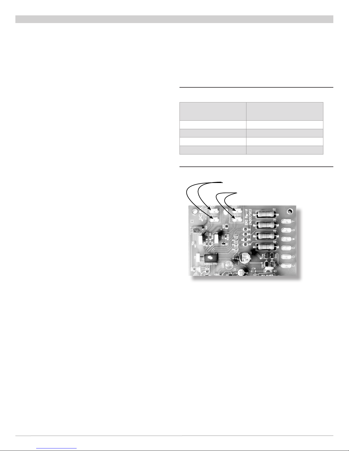
See Figure 17 for location of sensor connections to the
control board.
2.
If temperature response of indoor or outdoor sensor
is not correct, disconnect sensor from control board
and verify sensor resistance. Replace sensor if its
resistance is not close to values in the table below.
Table 2 - Sensor Resistance Values
@ Ambient
T e m p e r a t u r e
77°F (25°C) 10.0 K
50°F (10°C) 19.9 K
35°F (1.6°C) 30.0 K
30°F (-1.1°C) 34.4 K
Resistance
Figure 17 - Control Board Sensor Connections
Indoor Sensor Connections
Outdoor Sensor Connections
25 Made in USA
P/N 240010598, Rev. A [05/12/2014]
Page 26
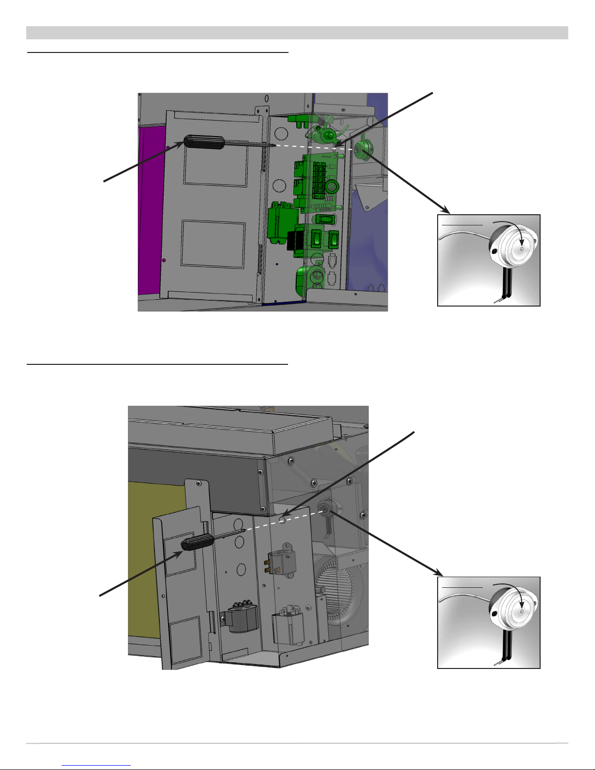
Figure 18 R40 Limit Switch Location
Use long blunt
tool to depress
limit switch reset
button
MAINTENANCE
Remove plug to access
Limit Switch Reset Button,
Replace Plug when
complete
Reset Button
*Note:
Button will pop
out when limit
switch opens. Push
in to reset.
Figure 19 R41 Limit Switch Location
Use long blunt
tool to depress
limit switch reset
button
Remove plug to access
Limit Switch Reset Button,
Replace Plug when
complete
Reset Button
*Note:
Button will pop
out when limit
switch opens. Push
in to reset.
The Right Fit for Comfort 26
P/N 240010598, Rev. A [05/12/2014]
Page 27
TROUBLESHOOTING
!
WARNING
Electrical shock hazard. Disconnect power to unit
before servicing or accessing control compartment.
Failure To follow these instructions could result in
death or serious injury.
Symptom Suggestion
No heat or cooling • Check to see if unit has power and if thermostat is satised. If
thermostat is not satised, call your installing contractor or service
contractor.
Thermostat calls for cooling, but
cool air is not coming out of unit.
Light on circuit board is
blinking.
Circuit board light is blinking 3
or 4 times, but there is no freeze
condition.
Thermostat is satised, but fan
is still running.
Thermostat calls for heat, but no
heat comes out of unit.
Thermostat calls for heat while in
heat pump mode, but heated air
is not coming out of unit.
• Check for continuity between thermostat and unit. Verify 24Vac is
present across terminals C and R.
• Verify high pressure switch located in outdoor section has not been
tripped. If tripped, press switch button to restart compressor.
• Note: If evaporator fan is operational and all of above suggested
procedures have been followed, and there is still no cooling being
supplied by unit, contact trained heating and cooling professional.
• Circuit board uses light for diagnostic purposes. Blinking codes are as
follows:
– 1 blink = normal operation
– 2 blinks = compressor lockout (ASCT — Anti-short cycle timer)
– 3 blinks = outdoor freeze condition
– 4 blinks = indoor freeze condition
– 5 blinks = simultaneous Y and W call (Straight cool units only)
• Verify sensors have not been damaged. Remove sensor wires from control
board and make resistance measurements, compare to following sensor
resistances. Indoor and outdoor coil sensor wires are labeled, as is control
board.
– 77°F = 10KOhms
– 50°F = 19.9KOhms
– 35°F = 30KOhms
– 30°F = 34.4KOhms
• If thermostat is set to auto mode, once thermostat is satised, fan will
stay energized for extra 60 seconds to purge unit of excess cool or warm
air in plenum.
• If thermostat fan switch is set to ON, fan will stay energized regardless
of whether thermostat is satised or not. Only way to turn fan off is to
turn unit off or turn thermostat fan switch to AUTO.
• Units equipped with electric heaters have temperature limit switch to
prevent electric heater from reaching unsafe temperatures. If after calling
for heating, heater is not energized, check for continuity across limit. If
limit is open, replace with equivalent limit switch.
• Verify unit has power or thermostat has been satised. If unit has power
and thermostat is satised, turn thermostat few degrees above room
temperature.
• While in heat pump mode, verify thermostat is not energizing O terminal.
Retroaire units are designed to work in heat pump mode when 24Vac
is present across Y and C. Verify heat pump jumper on control board
is jumping two pins labeled “HP”. See control board jumper locations,
Figure 9, Page 17.
• Verify there are no freeze conditions. Refer to blinking codes question
above for more information.
Have qualied technician conduct troubleshooting
procedures.
NOTICE
27 Made in USA
P/N 240010598, Rev. A [05/12/2014]
Page 28
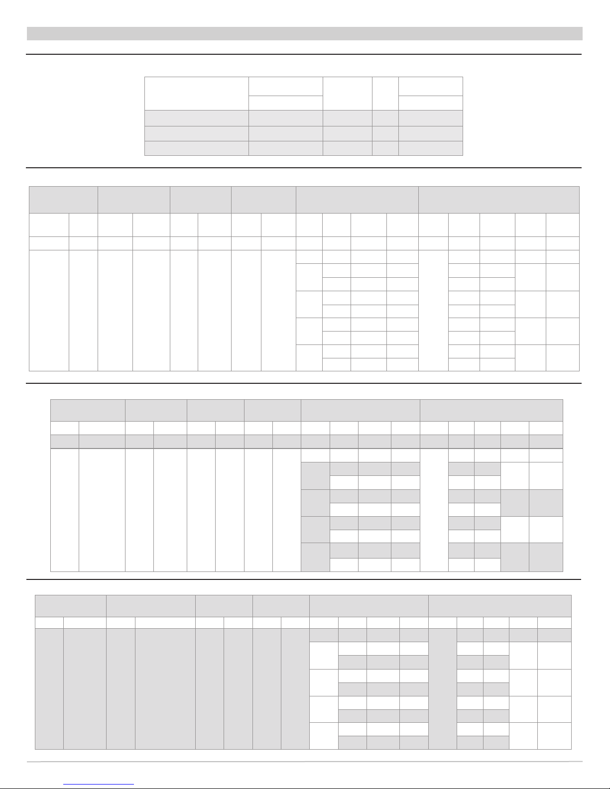
Table 3 R40C Performance Data
R40C - PERFORMANCE DATA
Model
R40
Cooling
Btuh (kW) CFM (L/s)
Sensible
Heat
Ratio
Indoor Air Flow
EER
R 40 C 09 9,000 (2.6) 0.7 8.98 350 (165)
R 40 C 12 10,800 (3.17) 0.6 8.6 350 (165)
R 40 C 15 13,200 (3.90) 0.6 8.09 350 (165)
Table 4 R40C - 9,000 BTU Electrical Specications
Power Supply
Volt 1–60
Compressor
Volt Min RLA LRA FLA Hp FLA Hp
115V 104 8.0 45.6 1.4 0.09 1.6 0.125 N/A N/A N/A N/A 11 N/A 13.0 20 5-15P
208/
230V
197 4.0 22.2 0.6 0.08 0.71 0.09
Indoor Fan
Motor
Outdoor Fan
Motor
Electric Heat Unit Electrical Ratings
Htr
Volt W HA TCA THA MCA MOCP Plug
#
0 N/A N/A N/A
208 1636 7.9 8.5 10.6
2
230 2000 8.7 9.3 11.6
208 2454 11.8 12.4 15.5
3
230 3000 13 13.6 17.1
208 3271 15.7 16.3 20.4
4
230 4000 17.4 18 22.5
208 4089 19.7 20.3 25.3
5
230 5000 21.7 22.3 27.9
N/A 6.3 15 6-15P
5.3
15 6-15P
20 6-20P
25 6-30P
30 6-30P
Table 5 R40C - 12,000 BTU Electrical Specications
Power Supply
Volt — 1–60
Volt Min RLA LRA FLA Hp FLA Hp Htr # Volt W HA TCA THA MCA MOCP Plug
115V 104 9.2 55 1.4 0.09 1.6 1.25 0 N/A N/A N/A 12.2 N/A 14.5 25 5-20P
208/
230V
197 5.6 29 0.6 0.08 0.71 0.09
Compressor
Indoor Fan
Motor
Outdoor
Fan Motor
Electric Heat Unit Electrical Ratings
0 N/A N/A N/A
208 1636 7.9 8.5 10.6
2
230 2000 8.7 9.3 11.6
208 2454 11.8 12.4 15.5
3
230 3000 13 13.6 17.1
208 3271 15.7 16.3 20.4
4
230 4000 17.4 18 22.5
208 4089 19.7 20.3 25.3
5
230 5000 21.7 22.3 27.9
N/A 8.3 15 6–15P
6.9
15 6–15P
20 6–20P
25 6-30P
30 6-30P
Table 6 R40C - 15,000 BTU Electrical Specications
Power Supply
Volt — 1–60
Volt Min RLA LRA FLA Hp FLA Hp Htr # Volt W HA TCA THA MCA MOCP Plug
208/
230V
197 6.6 33 0.6 0.08 0.71 0.09
Compressor
Indoor Fan
Motor
Outdoor
Fan Motor
Electric Heat Unit Electrical Ratings
0 N/A N/A N/A
208 1636 7.9 8.5 10.6
2
230 2000 8.7 9.3 11.6
208 2454 11.8 12.4 15.5
3
230 3000 13 13.6 17.1
208 3271 15.7 16.3 20.4
4
230 4000 17.4 18 22.5
208 4089 19.7 20.3 25.3
5
230 5000 21.7 22.3 27.9
N/A 9.6 15 6–15P
8.7
15 6–15P
20 6–20P
25 6-30P
30 6-30P
The Right Fit for Comfort 28
P/N 240010598, Rev. A [05/12/2014]
Page 29
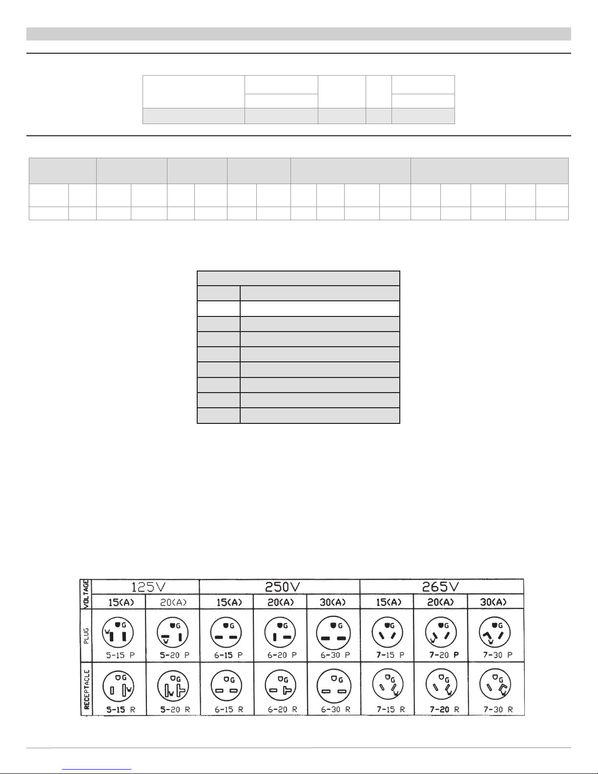
Table 7 R41C Performance Data
R41C - PERFORMANCE DATA
Model
R40
R 40 CA09 9,000 (2.6) 0.7 8.98 350 (165)
Cooling
Btuh (kW) CFM (L/s)
Sensible
Heat
Ratio
Indoor Air Flow
EER
Table 8 R41C - 9,000 BTU Electrical Specications
Power Supply
Volt 1–60
Volt Min RLA LRA FLA Hp FLA Hp
115V 104 7.5 47 1.4 0.09 1.6 0.125 5 115 1250 10.9 10.5 12.3 15.3 20 5-20P
Compressor
Indoor Fan
Motor
Outdoor Fan
Motor
Htr
#
LEGEND
Electric Heat Unit Electrical Ratings
Volt W HA TCA THA MCA MOCP Plug
RLA Rated Load Amps
FLA Full Load Amps
Hp Horse Power
W Watts
HA Heater Amps
TCA Total Cooling Amps
THA Total Heating Amps
MCA Minimum Circuit Amps
MOCP Maximum Over Current Protection
29 Made in USA
P/N 240010598, Rev. A [05/12/2014]
Page 30
NOTES
The Right Fit for Comfort 30
P/N 240010598, Rev. A [05/12/2014]
Page 31
LIMITED PRODUCT WARRANTY
RetroAire offers to the original purchaser/owner that under normal use and maintenance for comfort cooling and
conditioning applications, all RetroAire equipment will be free from defects in material and workmanship for a period of 12
months from the documented date of original installation or 18 months from the date of manufacture, if the documented
date of original installation is not available. Unit compressors shall be free from defects in materials and workmanship
under normal use and maintenance for a period 60 months from the documented date of original installation or 66 months
from the date of manufacture, if the documented date of original installation is not available.
WHAT RETROAIRE WILL WARRANT:
ECR will provide a replacement for or, at the discretion of RetroAire, repair any functional component that proves to be
defective in material or workmanship, under normal maintenance and operating conditions, within the prescribed warranty
period. Said parts will be supplied via standard shipping; billed and then credited back, when the defective component is
returned, at the sole discretion of RetroAire. However, the replacement cost shall NOT include labor or service costs to
diagnose, remove, or install a warranty part, or return of defective materials, at the sole discretion of RetroAire.
WHAT RETROAIRE WILL NOT WARRANT:
Damages to or arising from: misapplication, improper installation or service; components not supplied or approved by
RetroAire, including, without limitation, cabinetry, wall sleeves, louvers, internal components, equipment, or controls
supplied by others; and lack of preventative maintenance such as, but not limited to, replacing air filters, general cleaning,
clearing condensate drains, air flow adjustments; products manufactured or distributed by RetroAire but installed outside
the United States and Canada; unauthorized alteration, application or improper operation; excessively corrosive
installation environments; equipment usage during construction; shipping or handling.
RETROAIRE IS ALSO NOT RESPONSIBLE FOR:
Damages caused by faulty or interrupted power supply or electrical service; Damages caused by acts of God including,
but not limited to, wind, hail, floods, lightning, earthquakes or other conditions beyond the control of RetroAire.
FURTHER LIMITATIONS:
All implied warranties of merchantability and/or fitness for any particular purpose are limited in duration to the period of the
limited warranty. The rights and remedies provided herein are exclusive and constitute the entire contract. This limited
warranty and any optional extended warranties are granted only to the original owner/user. This warranty becomes null
and void if payment for the goods or product is in default. Warranty remedies may be withheld if the customer account is
in arrears or default.
In no event shall RetroAire be liable (whether for breach of this limited warranty or contract, for strict liability for
negligence, or otherwise), for any special, incidental, punitive or consequential damages, including, without limitation,
damages for loss of profits, loss of goodwill, loss of time or convenience, loss of use of the product, the cost of a product
rental, costs of gasoline, electricity, telephone, travel or lodging, or the loss of personal or commercial property, whether
or not RetroAire has been advised of the possibility of any such damages.
In no event shall RetroAire’s obligations under this limited warranty exceed the purchase price of the product.
Any repairs performed under this limited warranty shall not in any way extend the statute of limitations for claims under
this limited warranty.
No agent, representative or distributor of RetroAire has any authority to alter the terms of this limited warranty in any way.
For Service or Repair:
1) Contact the installing contractor
2) Call the nearest RetroAire sales rep/distributor
3) Call, E-Mail or write:
RetroAire, c/o ECR International, Inc., 2201 Dwyer Avenue, Utica, NY 13501, Ph: 1-800-325-5479
Fax: 1-866-432-7329, E-Mail: [email protected], Web: www.RetroAire.com.
P/N 240009782 Rev B (9/2013)
31 Made in USA
P/N 240010598, Rev. A [05/12/2014]
Page 32

TM
ECR International, Inc.
2201 Dwyer Avenue • Utica, New York 13501
Phone: 1.800.325.5279 • Web: retroaire.com
 Loading...