

Page 1

Page 2
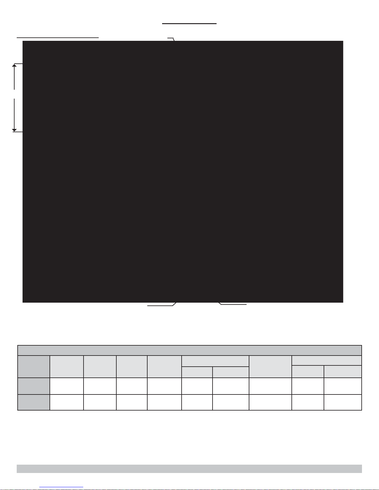
DIMENSIONS
FIGURE 1-1 Dimensions
(D)
(D)
Floor
(B)
(F)
Wall Hanging
Vent Connection
Supply Water
(E)
Gas
Connection
(G)
Bracket
(D)
Combustion Air
Return Water
(E)
User Interface
(A)
(B)
Size
075
100
Width
(A)
22-1/16"
(560mm)
22-1/16"
(560mm)
Height
(B)
35-5/8"
(905mm)
35-5/8"
(905mm)
Alternate Gas
Connection
(F)
Alternate
Supply Water
(E)
Table 1 : Physical Data
Depth
(C)
16-3/16"
(411mm)
16-3/16"
(411mm)
Bracket
27-1/2"
(969mm)
27-1/2"
(969mm)
(D)
(C)
Return Water
Water Connections
Size (E) Height (F)
1-1/4"
NPT
1-1/4"
NPT
38"
(965mm)
38"
(965mm)
Alternate
(E)
Gas
Connection
(G)
1/2" NPT
1/2" NPT
Weight
Shipping Unit
140 lb
(63.5 kg)
140 lb
(63.5kg)
115 lb
(51.2 kg)
115 lb
(51.2 kg)
2
Page 3

1 - TABLE OF CONTENTS
1 - Introduction ............................................................................................................................... 4
2 - Important safety Information ....................................................................................................5
3 - Component Listing .....................................................................................................................6
4 - Locating Boiler ......................................................................................................................... 10
5 - Hydronic Piping ........................................................................................................................12
5.2 Special Conditions ................................................................................................................... 12
5.3 Safety Relief Valve and Air Vent........................................................................................... 12
5.4 Trim Piping ............................................................................................................................. 13
5.5 System Piping ......................................................................................................................... 13
6 - Combustion Air And Vent Piping ............................................................................................... 18
6.2 Removal of Existing Boiler From Common Vent System.................................................................18
6.3 Materials ............................................................................................................................... 18
6.4 Pipe Installation ...................................................................................................................... 19
6.5 Termination ............................................................................................................................ 19
6.6 Condensate Piping ................................................................................................................... 24
7 - Gas Supply Piping ....................................................................................................................25
8 - Electrical Connections .............................................................................................................. 27
8.2 Line Voltage Connections .......................................................................................................... 27
8.3 Low Voltage Connections .......................................................................................................... 27
9 - Start Up Procedure ................................................................................................................... 29
10 - Operating Instructions ...........................................................................................................34
11 - General Maintenance And Cleaning ........................................................................................35
12 - Ratings And Capacities ........................................................................................................... 38
13 - Trouble Shooting ....................................................................................................................39
15 - Wiring Diagram ......................................................................................................................56
16 - Glossary .................................................................................................................................58
Appendix A - Control Module .........................................................................................................59
1.1 Introduction ............................................................................................................................ 59
1.2 Operation ................................................................................................................................59
1.3 Status Indication ...................................................................................................................... 59
1.4 Sequence of Operation .............................................................................................................. 60
1.5 Theory of Operation ................................................................................................................. 62
3
Page 4

1 - INTRODUCTION
1.1 Designated Use
Hot water heating boiler.•
Indoor installations.•
Closet or alcove installation.•
Direct vent boiler.•
For use with natural gas or liquefi ed petroleum gases •
(LP/propane).
1.2 The unit MUST NOT:
• Directly heat potable water. Indirect heating is acceptable.
• Heat water with non-hydronic heating system chemicals
present (example, swimming pool water).
Exceed 50 psig (344 kPa) system pressure.•
Exceed 200°F (93°C) system design temperature.•
1.3 Operational Features
Modulating: 20-100%.•
Integral Dual Limit.•
Integral Low Water Cutoff.•
Outdoor Temperature Reset.•
Integral Multiple Boiler Control.•
Auto Low Voltage or Intermittent Power Reset.•
4
Page 5
!
This is the safety alert symbol. Symbol alerts you to
potential personal injury hazards. Obey all safety messages
following this symbol to avoid possible injury or death.
2.2
Become familiar with symbols identifying
potential hazards.
2 - Important safety Information
2.1 General
Boiler installation shall be completed by qualifi ed agency.
See glossary for additional information.
WARNING
!
Fire, explosion, asphyxiate and electrical shock
hazard. Improper installation could result in death
or serious injury. Read this manual and understand
all requirements before beginning installation.
2.2
Become familiar with symbols identifying
potential hazards.
This is the safety alert symbol. Symbol alerts you to
potential personal injury hazards. Obey all safety messages
following this symbol to avoid possible injury or death.
!
DANGER
Indicates a hazardous situation which, if not avoided,
WILL result in death or serious injury
!
WARNING
Indicates a hazardous situation which, if not avoided,
could result in death or serious injury.
!
CAUTION
Indicates a hazardous situation which, if not avoided,
could result in minor or moderate injury.
Installation shall conform to requirements
2.3
of authority having jurisdiction or in absence of
such requirements:
United States
•
National Fuel Gas Code, ANSI Z223.1/NFPA 54•
National Electrical Code, NFPA 70.•
Canada •
Natural Gas and Propane Installation Code, •
CAN/CSA B149.1.
Canadian Electrical Code, Part I, Safety Standard •
for Electrical Installations, CSA C22.1
.
2.4 Where required by authority having
jurisdiction, installation shall conform to
Standard for Controls and Safety Devices for
Automatically Fired Boilers, ANSI/ASME CSD-1.
Additional manual reset low water cutoff may be required.
2.5 Requirements for Commonwealth of
Massachusetts:
Boiler installation must conform to state code 248 CMR
which includes but is not limited to:
Installation by licensed plumber or gas fi tter.•
Carbon monoxide detectors with side wall horizontally •
vented gas-fuel equipment in residential dwelling,
building or structure.
NOTICE
Used to address practices not related to personal
injury.
5
Page 6

Return Water From Heating System (In) 1-1/4"
NPT
(see pages 7 & 8)
-
Connections supplied to con-
nection top and/or bottom of boiler.
Low Voltage Terminal Strip
(see pages 7 & 8)
- Connection of all low voltage wiring, including
thermostat. See section
8.
Heat Exchanger Pump Pump
Gas Shutoff Valve
- Fuel supply isolation
during servicing. See section 7
Combustion Air Blower
- Delivers
proper quantity of combustion air, receives fuel from
gas valve, mixes air and fuel sending mixture to burner
for combustion.
Gas (Control) Valve
- Delivers
proper quantity of fuel to Combustion Air Blower.
See section 7.
High Temperature Supply Switch
Low Water Cutoff
Senses inadequate
quantity of water. Turns off boiler before damage can
occur.
8
Gas Connection
- Gas supply may be
piped either through top or bottom of boiler. See
section 7.
Control Module
3 - COMPONENT LISTING
3.1 COMPONENT LISTING
User Interface
1.
tion regarding boiler condition. Allows adjustment of
boiler operating parameters. NOTE: Does not replace
thermostat used to control central heating space.
2.
Combustion Air Inlet (2" PVC)
Return Water From Heating System (In) 1-1/4"
3.
NPT
(see pages 7 & 8)
nection top and/or bottom of boiler.
Low Voltage Terminal Strip
4.
- Connection of all low voltage wiring, including
thermostat. See section
Igniter
5.
Flame Sensor
6.
Sight Glass
7.
burner fl ame.
Burner
8.
(see page 8)
(see page 8)
(see Page 8) - Displays informa-
(see page 7 & 8)
-
Connections supplied to con-
(see pages 7 & 8)
8.
(see page 8)
(see page 8) - Permits observation of
Gas (Control) Valve
20.
proper quantity of fuel to Combustion Air Blower.
See section 7.
High Temperature Supply Switch
21.
Low Water Cutoff
22.
quantity of water. Turns off boiler before damage can
occur.
Safety Relief Valve
23.
section 5.
High Voltage Junction Box
24.
connection of 120V components. See section
Vent Connector (2" PVC)
25.
section 6.
Gas Connection
26.
piped either through top or bottom of boiler. See
section 7.
Bracket for Optional Wall Mount
27.
Integral to boiler. Allows optional wall mounting when
used with supplied wall mounting bracket. See section 4.
(see page 8)
(see page 8) --
(see page 8) - Field installed. See
(see page 8) - For
(see pages 7 & 8) - See
(see page 7)
- Delivers
(see page 8)
Senses inadequate
8.
- Gas supply may be
(see page 7) -
Combustion Chamber
9.
Condensate Collector
10.
Return Temperature Sensor
11.
Drain Valve
12.
Heat Exchanger Ball Valve
13.
14.
Supply Water Outlet to Heating System (Out)
1-1/14"NPT (see pages 7 & 8) - Connections supplied
for connecting from either top or bottom of boiler. See
section 5.
Vent Temperature Sensor
15.
Condensate Drain
16.
a liquid (condensate) as a by-product of combustion.
Condensate must be piped to appropriate drain. See
section 6.
Heat Exchanger Pump Pump
17.
(see page 8)
(see page 8)
(see page 8)
(see page 8)
(see page 8)
(see page 8)
(see page 8) - Boiler produces
(see page 8)
Auxiliary Power Outlet
28.
outlet for condensate pump or service. Controlled by
Service Switch (28)
Service Switch
29.
Air Vent
30.
Central Heating Pump Circuit Breaker
31.
5 amp circuit breaker protects control module.
Control Module
32.
Internal Access Panel
33.
upward then forward to access control module.
Removable for access to internal components of boiler.
Central Heating Pump Relay
34.
Transformer
35.
water cutoff.
36.
Air Pressure Switch
(see page 7)
(see page 7)
(see page 9)
(see page 9) - Supplies 24V power to low
(see page 7) - Convenience
(see page 7)
(see page 9) - Gently pull
(see page 9)
(not shown) - see page 31
Gas Shutoff Valve
18.
during servicing. See section 7
Combustion Air Blower
19.
proper quantity of combustion air, receives fuel from
gas valve, mixes air and fuel sending mixture to burner
for combustion.
(see page 8)
(see page 8)
- Fuel supply isolation
- Delivers
Flue Transition Test Port
37.
Combustion Air Analysis Test Port
38.
(see page 8)
(37) (see page 8)
6
(38)
Page 7

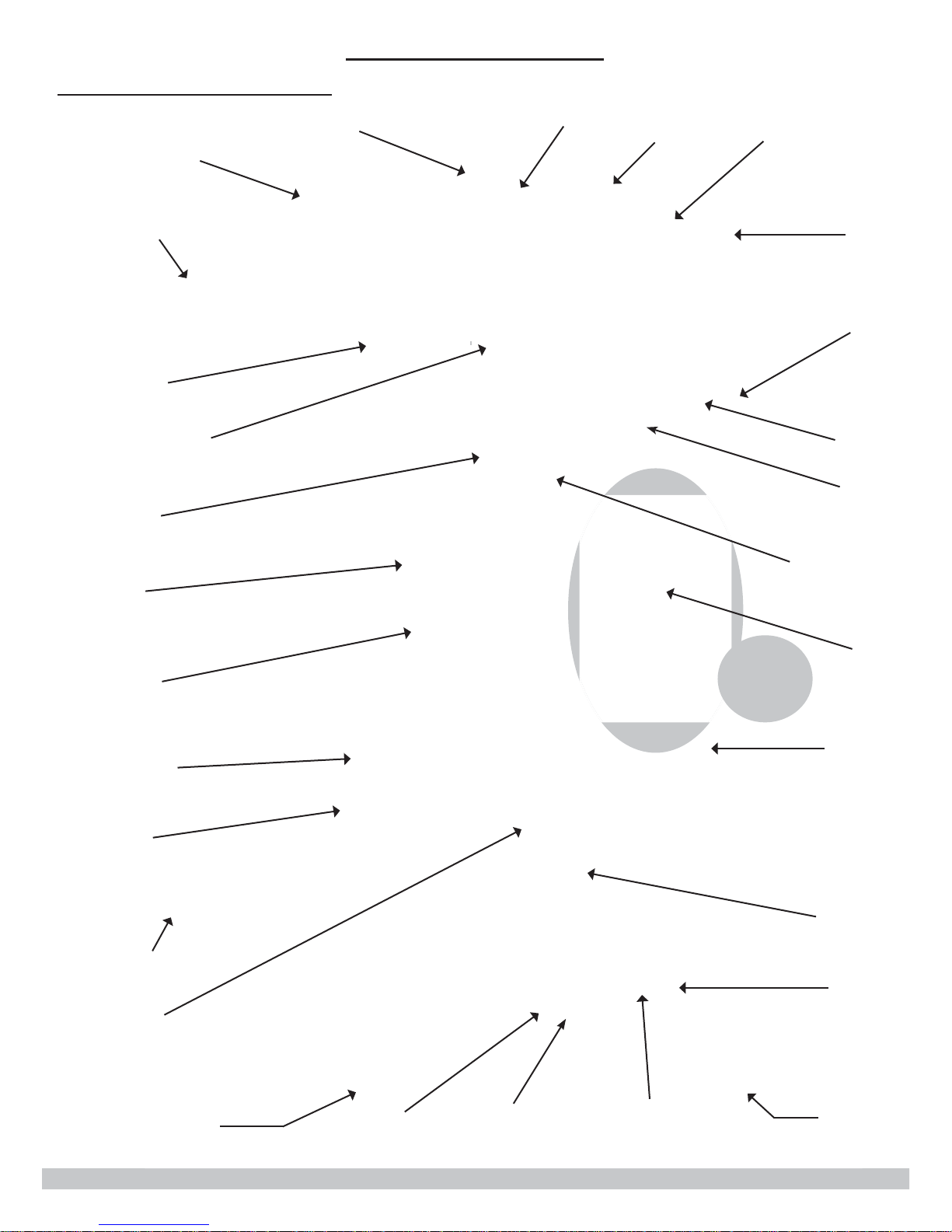
FIGURE 3-1 Boiler Components
LOW VOLTAGE
TERMINAL
STRIP (4)
SAFETY
RELIEF
VALVE
(23)
AIR VENT
(30)
RETURN WATER
FROM HEATING
SYSTEM (IN) (3)
HIGH VOLTAGE
JUNCTION BOX
(24)
SUPPLY WATER TO
HEATING SYSTEM
(OUT) (14)
GAS CONNECTION
(26)
SERVICE SWITCH
(29)
AUXILIARY POWER
OUTLET (28)
CENTRAL HEATING
PUMP CIRCUIT BREAKER
(31)
BRACKET FOR
OPTIONAL WALL
MOUNT (27)
LOW VOLTAGE
TERMINAL
STRIP (4)
COMBUSTION
AIR INLET- 2" PVC
(2)
3 - COMPONENT LISTING
VENT
CONNECTOR - 2" PVC
(25)
HIGH VOLTAGE
JUNCTION BOX
(24)
SAFETY
RELIEF
VALVE
(23)
AIR VENT
(30)
RETURN WATER
FROM HEATING
SYSTEM (IN) (3)
BRACKET FOR
OPTIONAL WALL
MOUNT (27)
SUPPLY WATER TO
HEATING SYSTEM
(OUT) (14)
GAS CONNECTION
(26)
SERVICE SWITCH
(29)
AUXILIARY POWER
OUTLET (28)
PUMP CIRCUIT BREAKER
CENTRAL HEATING
(31)
7
Page 8
3 - COMPONENT LISTING
LOW
VOLTAGE
TERMINAL
STRIP (4)
HIGH VOLTAGE
JUNCTION BOX
(24)
RETURN WATER
FROM HEATING
SYSTEM (IN)
1-1/4" NPT (3)
IGNITER
(5)
SIGHT
GLASS
(7)
HEAT EXCHANGER
BALL VALVE (13)
CONDENSATE
DRAIN 1/2" PVC
(16)
GAS SHUTOFF
VALVE (18)
LOW WATER
CUTOFF (22)
COMBUSTION
AIR
BLOWER (19)
COMBUSTION
CHAMBER
(9)
GAS (CONTROL)
VALVE (20)
USER INTERFACE (1)
RETURN WATER
FROM HEATING
SYSTEM (IN)
1-1/4" NPT
(3)
SUPPLY WATER TO
HEATING SYSTEM
(OUT) 1-1/4" NPT
(14)
HEAT EXCHANGER
PUMP
(17)
SAFETY RELIEF
VALVE (23)
COMBUSTION
AIR ANALYSIS
TEST PORT (38)
FIGURE 3-2 Boiler Components
HIGH VOLTAGE
JUNCTION BOX
(24)
SAFETY RELIEF
VALVE (23)
LOW WATER
CUTOFF (22)
HIGH TEMPERATURE
SUPPLY SWITCH
(21)
GAS (CONTROL)
VALVE (20)
COMBUSTION
AIR
BLOWER (19)
GAS SHUTOFF
VALVE (18)
(SHOWN IN OPEN
POSITION)
COMBUSTION
AIR ANALYSIS
TEST PORT (38)
VENT
CONNECTOR
2" PVC (25)
USER INTERFACE (1)
COMBUSTION
AIR INLET
2" PVC (2)
perspective
RETURN WATER
FROM HEATING
SYSTEM (IN)
1-1/4" NPT (3)
VOLTAGE
TERMINAL
STRIP (4)
IGNITER
FLAME SENSOR
FLUE
TRANSITION
TEST PORT
(37)
BURNER
View has
different
than boiler
COMBUSTION
CHAMBER
LOW
(5)
(6)
SIGHT
GLASS
(7)
(8)
(9)
HEAT EXCHANGER
PUMP
(17)
CONDENSATE
DRAIN 1/2" PVC
(16)
VENT
TEMPERATURE
SENSOR (15)
SUPPLY WATER TO
HEATING SYSTEM
(OUT) 1-1/4" NPT
(14)
HEAT EXCHANGER
BALL VALVE (13)
DRAIN
VALVE (12)
8
RETURN TEMPERATURE
SENSOR (11)
CONDENSATE
COLLECTOR
(10)
RETURN WATER
FROM HEATING
SYSTEM (IN)
1-1/4" NPT
(3)
Page 9
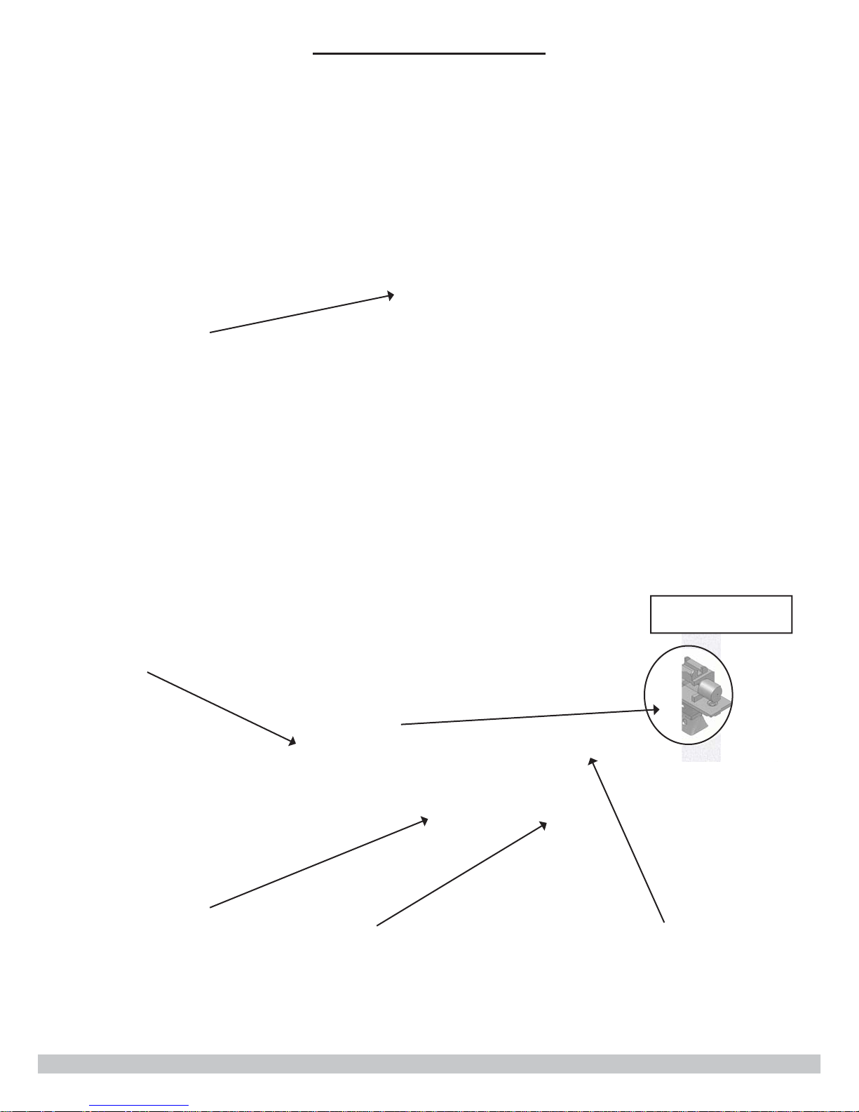
INTERNAL ACCESS
PANEL - CLOSED
(33)
3 - COMPONENT LISTING
CONTROL
MODULE
(32)
INTERNAL ACCESS
PANEL -OPEN
(33)
CENTRAL HEATING
PUMP RELAY
(34)
Control Module
Fuse and holder
TRANSFORMER
(35)
9
Page 10
4 - LOCATING BOILER
4.1 Boiler Location Considerations
Ambient room temperature always above 32°F (0°C) to •
prevent freezing of liquid condensate.
Approved for installation in closets and on combustible •
fl oors. Do not install boiler on carpeting.
Protection of gas ignition system components from •
water (dripping, spraying, rain, etc.) during operation
and service (circulator replacement, condensate trap,
control replacement, etc.).
Floor or wall mounting. •
Wall must be plumb and capable of supporting boiler •
weight plus 60 lbs (28 kg), see Table 12-1 (page 38)
Floor must be level. Leveling feet allow adjustment •
up to 1/4" (6 mm).
Wall mounting - see section 4.2•
Access to outdoors to meet minimum and maximum •
pipe lengths for combustion air and vent piping. See
section 6.
Disposal of condensate. See section 6.•
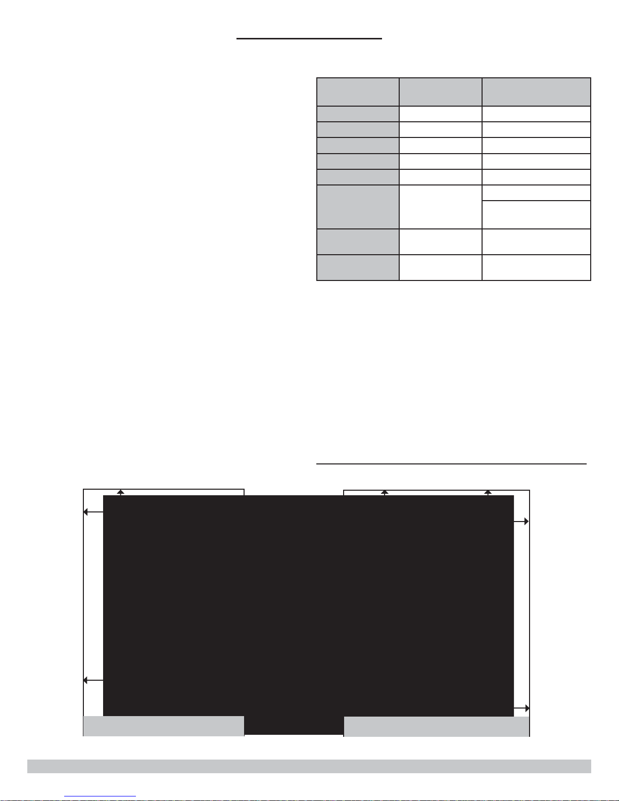
TABLE 2: BOILER CLEARANCES
Dimension
Top (A)
Left Side (B)
Right Side (C)
Front (D)
Back (E)
Bottom (F)
Combustion
Air/Vent piping
Hot Water Piping
(1)
Required distances measured from boiler.
(2)
Service clearance recommendation.
Combustible
Materials
0" (0 cm) 14" (36 cm)
6" (16 cm) 6" (16 cm)
0" (0 cm) 1½" (4 cm)
0" (0 cm) 6" (16 cm)
0" (0 cm) 0" (0 cm)
0" (0 cm)
0" (0 cm) 6" (16 cm)
1/2" (1.3 cm) 6" (16 cm)
(1)
Service
0" (0 cm) Floor
12" (32 cm) for
Bottom Piped
(1)(2)
Drainage of water (or water - antifreeze solution) during •
boiler service or from safety relief valve discharge. See
section 5.
Access to system water piping, gas supply, and electrical •
service. See Sections 5, 7 and 8.
Clearances to combustible materials and service •
clearances. See Table 2 and fi gure 4-1.
Multiple Boilers can be placed side by side, back to back •
or wall mounted.
FIGURE 4-1 Clearance to Combustible Materials
A
E
B
A
A
C
E
FLOOR
D
10
B
C
FLOOR
Page 11
4 - LOCATING BOILER
!
!
WARNING
Do not install wall mount bracket directly on drywall.
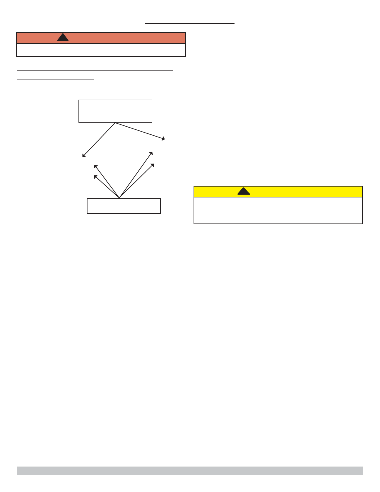
FIGURE 4-2 Wall Mounting Bracket Engaged
with Bracket on Boiler
Center brackets. Avoid
overhang on sides of wall
mount bracket.
4 Slots for attaching Wall
Mount Bracket to Studs
4.2 WALL MOUNTING OPTION
Boiler can be wall mounted using wall mounting bracket
included with unit.
1.
Structure must be capable of supporting boiler
weight plus 60 lbs (28 kg). See Table 1, page 2.
Wall mount bracket has 4 slots allowing mounting
2.
on two (2) wall studs spaced at 11½" to 16½" on
center. See fi gure 4-2.
Boiler includes (4) 3/8" x 3" lag screws and (4)
3.
washers for attaching wall mount bracket to wood
studs. Field source appropriate fasteners for other
wall constructions (masonry, concrete).
Attach wall mount bracket level on wall.
4.
Boiler must engage with wall mount bracket.
5.
Avoid overhang on sides of wall mount bracket.
6.
Verify boiler bracket is centered on wall bracket.
See fi gure 4-2.
!
CAUTION
Boiler weigh's approximately 100 pounds (45.4 kg)
without jacket. Do not lift boiler onto wall without
assistance.
11
Page 12
!
5 - HYDRONIC PIPING
5.1 General
Install piping in accordance with authority having jurisdiction.•
NOTICE
Use two (2) wrenches when tightening and fi tting
to pipe boiler's threaded fi ttings. Boiler's internal
piping can be damaged if subjected to excessive
torque.
Support system piping and safety relief valve discharge •
piping. Boiler's internal piping and wall mount bracket can
be damaged if subjected to excessive weight.
Size central heating pump (and domestic hot water pump, •
if used) for system requirements only. Boiler pump
compensates for pressure drop through boiler internal
piping and heat exchanger.
Thoroughly clean and fl ush system before connecting to •
boiler.
5.2 Special Conditions
System piping exposed to freezing conditions: Use •
inhibited proplyene glycol solutions certifi ed by fl uid
manufacturer for use with closed water heating system.
Do not use automotive or ethylene glycol.
Boiler installed above radiation level (or as required by •
authority having jurisdiction). Intergral low water cutoff
provided in boiler (see page 6).
!
CAUTION
Non-potable water only piped directly to boiler. DO
NOT connect drinking water to heating system.
!
WARNING
Poison hazard. Ethylene glycol is toxic. Do not •
use ethylene glycol.
Never use automotive or standard glycol antifreeze, •
even ethylene glycol made for hydronic systems.
Ethylene glycol can attack gaskets and seals used •
in hydronic systems.
Use only inhibited proplyene glycol solutions •
certifi ed by fl uid manufacturer as acceptable for
use with closed water heating system.
Thoroughly clean and fl ush any system that used •
glycol before installing new Boiler.
Provide user with Material Safety Data Sheet •
(MSDS) on fl uid used.
NOTICE
Do not expose boiler and condensate piping to
freezing temperatures.
Boiler used in connection with refrigeration system. •
Install piping in parallel with boiler, with appropriate
valves to prevent chilled medium from entering boiler.
System piping connected to heating coils located in air •
handling unit exposed to refrigerated air circulation.
Install fl ow control valves or other automatic means to
prevent gravity circulation of boiler water during cooling
cycle.
5.3 Safety Relief Valve and Air Vent
NOTICE
Field source safety relief valve for system pressures greater than 30 psig (206 kPa). Temperature-
Pressure Gauge and Air Vent satisfactory for 30-50
psig (206-345 kPa) operation.
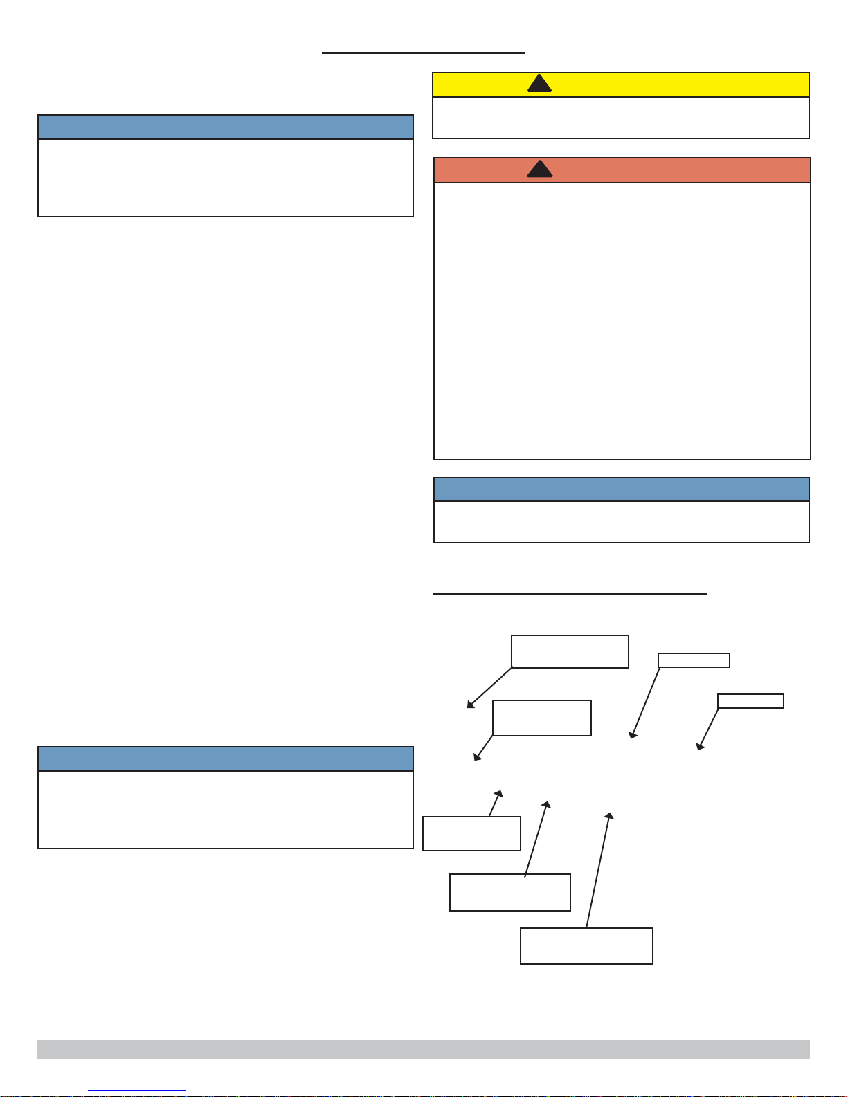
Install safety relief valve and air vent using pipe fi ttings •
provided with boiler. See fi gure 5-1
Install safety relief valve with spindle in vertical position.•
Do not install shutoff valve between boiler and safety •
relief valve.
FIGURE 5-1 Relief Valve & Air Vent
Safety Relief
Valve
Air Vent
3/4" NPT
90° Elbow
3/4" NPT
Close Nipple
3/4"F x 3/4"M
NPT Tee
3/4" x 1/4" NPT
90° Elbow
3/4 NPT
12
Page 13
5 - HYDRONIC PIPING
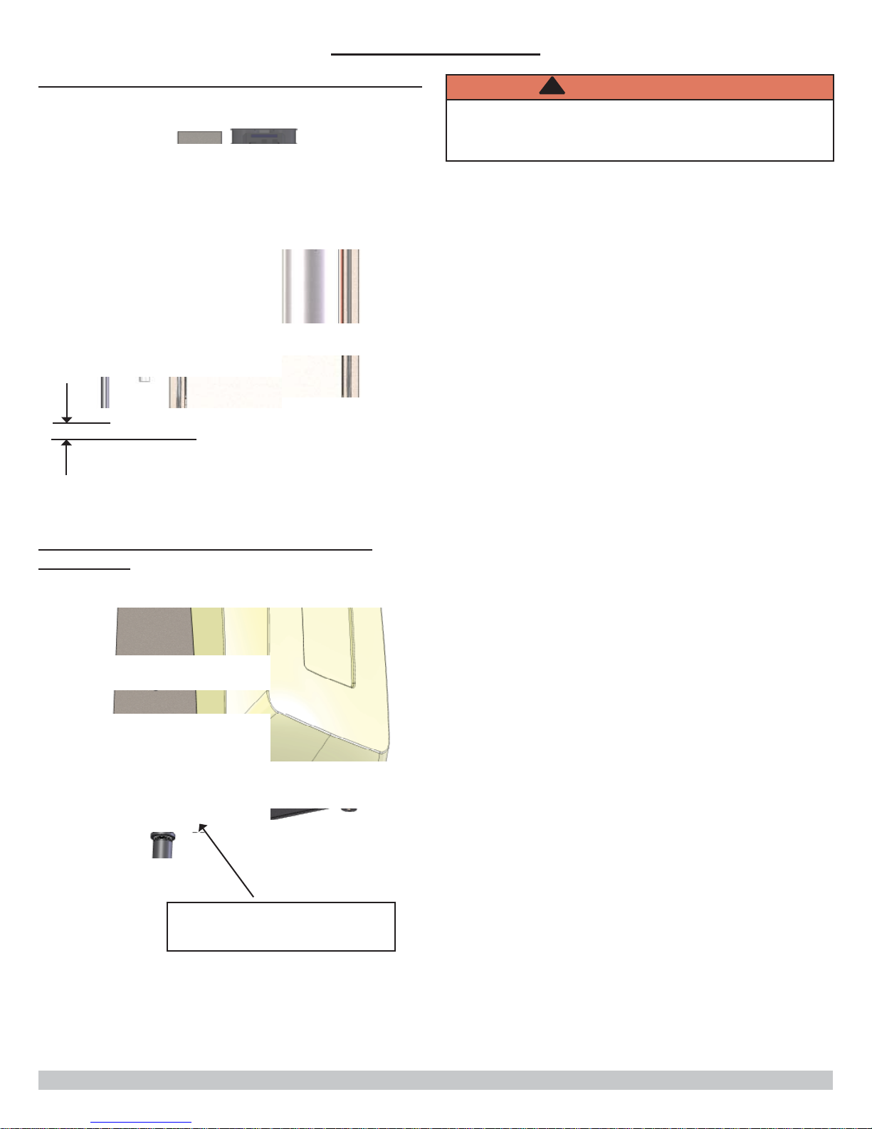
FIGURE 5-2 Safety Relief Valve Discharge Piping
Burn and scald hazard. Safety relief valve could
discharge steam or hot water during operation.
Install discharge piping per these instructions.
Check Local Codes
For Maximum
Distance To Floor
!
WARNING
Install discharge piping from safety relief valve. See •
fi gures 5-2 and 5-4.
Use ¾" or larger pipe.•
Use pipe suitable for temperatures of 375°F (191°C) •
or greater.
Individual boiler discharge piping shall be independent •
of other discharge piping.
Size and arrange discharge piping to avoid reducing •
safety relief valve relieving capacity below minimum
relief valve capacity stated on rating plate.
Run pipe as short and straight as possible to loca-•
tion protecting user from scalding and properly drain
piping.
Install union, if used, close to safety relief valve outlet.•
Install elbow(s), if used, close to safety relief valve •
outlet and downstream of union (if used).
Terminate pipe with plain end (not threaded).•
FIGURE 5-3 Temperature Pressure Gauge
Installation
Temperature Pressure Gauge
Located at Optional Bottom
Supply Connection to Boiler
5.4 Trim Piping
Supply and Return Piping•
Supply. Select either top or bottom supply options.•
Return. Select either top, bottom, or both.•
Install brass plug(s) provided with boiler in unused •
tapping(s).
Temperature - Pressure Gauge. Install temperature •
pressure gauge using nipple and tee provided with
boiler. See fi gure 5-3.
5.5 System Piping
Single boiler system. See fi gures 5-4, 5-5, 5-6, 5-7 for •
general guidance. Additional considerations:
Control system designed for single central heating •
pump. Installer responsible for integration of
multiple central heating pumps.
Control system allows domestic hot water •
prioritization. Function could be lost if central
heating pump not directly connected to control
system.
Multiple boiler system. See fi gure 5-8 for general guid-•
ance. Additional considerations:
Control system requires equivalent water •
temperatures entering each boiler to properly sequence and adjust system supply temperature.
Install multi boiler sensor kit. See parts list for part •
number.
13
Page 14
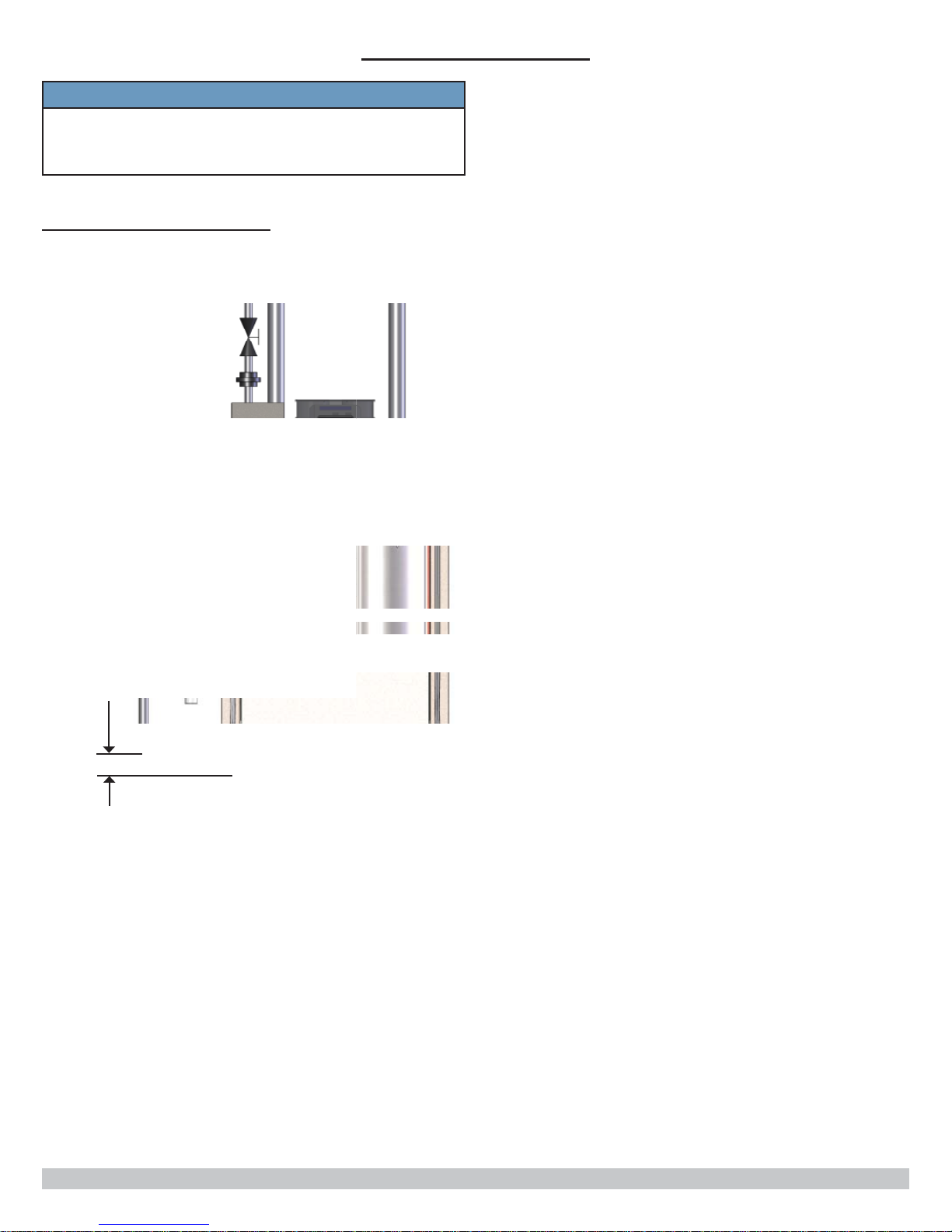
5 - HYDRONIC PIPING
NOTICE
Illustrations are meant to show system piping concept only. Installer responsible for all equipment and
detailing required by authority having jurisdiction.
FIGURE 5-4 System Piping
System
Supply
System
Return
Piping Legend
Check Local Codes
For Maximum
Distance To Floor
14
Page 15

5 - HYDRONIC PIPING
5-5 TWO-PIPE ZONED SYSTEM WITH VALVES
Circulating Ball
Valve Open
(as shipped)
5-6 TWO-PIPE ZONED SYSTEM WITH PUMPS
3/8" Open End Wrench
Circulating Ball
Valve Open
(as shipped)
3/8" Open End Wrench
15
Page 16

5 - HYDRONIC PIPING
5-7 SINGLE BOILER USING PRIMARY/SECONDAY PUMPING
12"/305mm Max. apart
12"/305mm
Max. apart
System
Pump
3/8" Open End Wrench
Heat Exchanger
valve open
Existing closely
spaced tees
in primary
system loop
Limit length to
5 feet water
pressure drop
Heat Exchanger
valves closed
3/8" Open End Wrench
16
Page 17

5 - HYDRONIC PIPING
5-8 TYPICAL MULTIPLE BOILER PIPING - (See Multiple Boiler Guide)
System
Pump
12"/305mm Max. apart
System
T emperature
Sensor
Size common piping
according to max.
heat capacity of
entire system
Limit to
2 feet
Up to 16
boilers
All heat exchanger
valves closed
3/8" Open End Wrench
17
Page 18
6 - COMBUSTION AIR AND VENT PIPING
6.1 General
This boiler requires a dedicated direct vent system.
Install air and vent piping in accordance with these
instructions, authority having jurisdiction, and:
USA - National Fuel Gas Code, ANSI 223.1/NFPA 54.•
Canada - Natural Gas and Propane Installation Code, •
CAN/CSA B149.1
Vent connections serving appliances vented by natural draft
shall not be connected into any portion of mechanical draft
systems operating under positive pressure.
6.2 Removal of Existing Boiler From Common
Vent System
When existing boiler is removed from common venting
system, common venting system is likely to be too large for
proper venting of appliances remaining connected to it.
At removal of existing boiler, following steps shall be
followed with each appliance remaining connected to
common venting system placed in operation, while other
appliances remaining connected to common venting system
are not in operation:
Seal any unused openings in common venting system.•
Visually inspect venting system for proper size and •
horizontal pitch. Determine there is no blockage or
restrictions, leakage, corrosion and other defi ciencies
which could cause an unsafe condition.
When practical, close all building doors, windows, and •
all doors between space in which appliances remaining
connected to common venting system are located and
other spaces of building. Turn on clothes dryer and any
appliance not connected to common venting system.
Turn on exhaust fans, such as range hoods and bathroom exhaust so they will operate at maximum speed.
Do not operate summer exhaust fan. Close fi replace
dampers.
Any improper operation of common venting system •
should be corrected so installation conforms with National
Fuel Code, ANSI Z223.1/NFPA 54 and/or Natural Gas
and Propane Installation Code, CAN/CSA B149.1. When
re-sizing any portion of common venting system, common
venting system should be re-sized to minimum size as
determined using appropriate tables Chapter 13 of the
National Fuel Gas Code, ANSI Z223.1/NFPA 54 and/or
Natural Gas and Propane Installation Code, CAN/CSA
B149.1.
6.3 Materials
See Table 4•
Table 3 - Combustion Air and Vent Piping Length
Combustion Air and Vent Pipe Equivalent
Length
2” Pipe 3” Pipe
Minimum 6 ft (1.8 m) 6 ft (1.8 m)
Maximum 60 ft (18.3 m) 100 ft (30.4 m)
1 - 90° elbow = 5 ft (1.6 m)
1 - 45° elbow = 3.5 ft (1.1 m)
1- 2" x 3" adapter = 0 ft. (0 m)
For Example: Boiler can be installed on outside wall and
vented with 1-90° elbow and 2 feet of vent pipe.
Turn on appliance being inspected. Follow lighting •
instructions. Adjust thermostat so appliances will operate
continuously.
Test for spillage at draft hood relief opening after 5 •
minutes of main burner operation. Use fl ame of match or
candle, smoke from cigarette, cigar or pipe.
Determine each appliance remaining connected to •
common venting system properly vents when tested as outlined above. Then return doors, windows,
exhaust fans and any other gas-burning appliance to
their previous condition of use.
18
Page 19
6 - COMBUSTION AIR AND VENT PIPING
Table 4 - Combustion air and vent pipe fi ttings
must conform with the following:
Item Material Standards
PVC schedule 40 ANSI/ASTM D1785
PVC - DWV ANSI/ASTM D2665
CPVC schedule 40
Vent Pipe
and Fittings
Pipe Ce-
ment/
Primer
IPEX is approved vent manufacturer in Canada listed •
to ULC-S636.
IPEX System 636 Cements and Primers are approved •
in Canada listed to ULC-S636.
SDR-21 & SDR-26 PVC ANSI/ASTM D2241
ABS-DWV ANSI/ASTM D2661
Schedule 40 ANSI/ASTM F628
PVC ANSI/ASTM D2564
CPVC ANSI/ASTM F493
Schedule 40 ABS ANSI/ASTM D2235
DO NOT USE CELLULAR (FOAM) CORE PIPE
!
WARNING
ANSI/ASTM D1784/
F441
Use of cellular core PVC for venting fl ue gas could
result in death, serious injury.
!
WARNING
Exhaust vent extending through exterior wall shall
not terminate adjacent to wall or below building
extensions such as eaves, balconies, parapets or
decks. Failure to comply could result in death or
serious injury.
6.4 Pipe Installation
Minimum and maximum combustion air and vent pipe •
lengths listed in Table (3). Pipe length counted from
combustion air connector to termination.
Install fi eld-sourced 2" to 3" transition, if used, in vertical •
section at combustion air inlet and vent connector.
90° elbows equivalent to 5.0 ft (1.6 m). 45° elbows •
equivalent to 3.5 ft (1.1 m). 2" to 3" transition has no
equivalent length.
Slope vent pipes minimum 1/4" per foot (21 mm/m) •
back toward boiler. Vent piping must be above boiler
vent connector. Provide condensate drain tee(s) in
piping below boiler. Avoid sags capable of accumulating
condensate.
Support piping in accordance with pipe manufacturer's •
instruction and authority having jurisdiction. In absence
of manufacturer's instruction use pipe hooks, pipe
straps, brackets, or hangers of adequate and strength
located at intervals of 4 ft (1.2 cm) or less. Allow for
expansion/contraction of pipe do not restrict.
Combustion air and vent piping must be air tight and •
water tight.
Certifi ed vent system components must NOT be inter-•
changed with other vent systems or unlisted pipe/fi ttings.
Canadian installations only. All plastic venting •
material,primer and glue must be listed to ULC S636.
Canadian installations only. First 3 ft (0.9 m) of plastic •
vent pipe from appliance fl ue outlet must be readily ac-
cessible for visual inspection.
6.5 Termination
Terminate combustion air and vent pipes with fi ttings or •
concentric vent kit.
See "Parts, Kits and Optional Accessory" manual •
for concentric vent kit part numbers. Follow
instructions provided with kit.
Use horizontal pipe for vent and 90° elbow for •
combustion air termination when using fi ttings.
Terminate combustion air and vent pipes in same •
atmospheric pressure zone through exterior sidewall or
roof.
Locate combustion air termination as far as possible •
from swimming pool, swimming pool pump house, and
other sources of airborne chlorine.
Locate combustion air and vent as required by authority •
having jurisdiction.
19
Page 20
6 - COMBUSTION AIR AND VENT PIPING
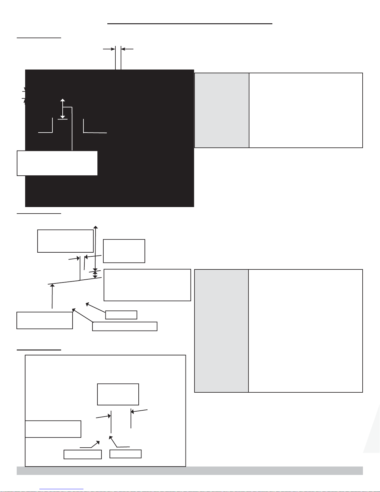
FIGURE 6-1
12" (30 cm)
Minimum
8" (21 cm)
Minimum
Exhaust Combustion
12" (30 cm) 18" (46 cm)
Canada Minimum above
anticipated snow line
FIGURE 6-2
3" (8 cm)
Maximum
Air
15" (38 cm)
Maximum
Roof
Terminations
3" (8 cm) Maximum horizontal
separation between combustion air
intake and exhaust
8" (21 cm) Minimum vertical
separation between combustion air
intake and exhaust.
15" (38 cm) Maximum horizontal
length of exhaust.
Properly support all piping.
12" (30 cm)
Minimum from
overhang
See snow & ice
page 20
FIGURE 6-3
3" (8 cm)
Maximum
separation
12" (30 cm) Separation
between bottom of
combustion air intake
and bottom of exhaust
Exhaust
Combustion Air
12" (30cm)
Minimum
separation
Side Wall
Terminations
3" (8 cm) Minimum horizontal
separation between combustion air
intake and vent terminations.
8" (21 cm) Minimum vertical separ ation
between combustion air intake and
vent terminations.
12" (30 cm) Separation between
bottom of combustion air intake
and bottom of exhaust.
Multiple terminations as shown in
6-1, 6-2, and 6-3 must be a minimum
of 12” (300 mm) horizontally between
exhaust of one termination and air
intake of next termination.
Properly support all piping.
See snow & ice
page 20
Air Intake
Exhaust
20
Page 21
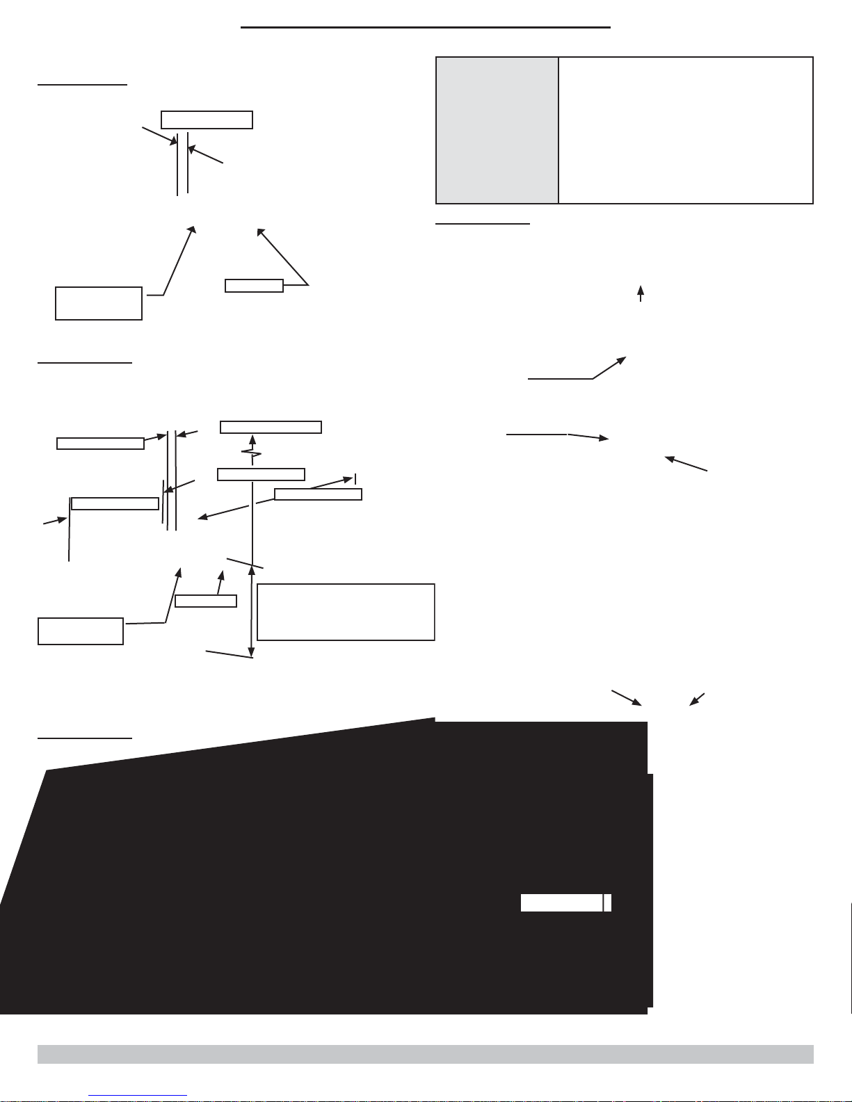
6 - COMBUSTION AIR AND VENT PIPING
FIGURE 6-4
Combustion
Air
FIGURE 6-5
1" Maximum
12" Minimum
1" Maximum
Exhaust
Roof overhang
12" Minimum
36" Minimum
Maintain 12" (18" for Canada)
minimum clearance above highest
Concentric
Vent Roof
Terminations
anticipated snow level. Maximum
of 24" above roof.
Support must be fi eld installed to
secure termination kit to structure.
Elbow, Roof Boot/Flashing fi eld
supplied.
FIGURE 6-6
Maintain 12" (30 cm)
18" (46 cm) Canada
Minimum clearance
above highest
anticipated snow
level maximum of 24"
above roof
Combustion Air
Roof boot/fl ashing
(fi eld supplied)
Exhaust
Support
(fi eld supplied)
Combustion
Air
FIGURE 6-7
Exhaust
Exhaust
Combustion Air
Elbow fi eld
supplied
Exhaust
Note: Support must
Maintain 12"
clearance above
Maintain 12" (18" Canada)
highest anticipated
clearance above highest
snow level or grade
anticipated snow level or
grade
be fi eld installed to
secure termination
kit to structure
Exhaust
Combustion Air
1-1/2"
(3.8 cm)
1" Maximum
1-3/16"
(4.0 cm)
31-7/8"
(0.8 m)
3" (7.6 cm) Diameter PVC intake/combustion air
46-3/4" (1.2 m)
Combustion Air
Exhaust
Note: Securing strap must
be fi eld installed to prevent
movement of termination
kit in side wall
21
Page 22
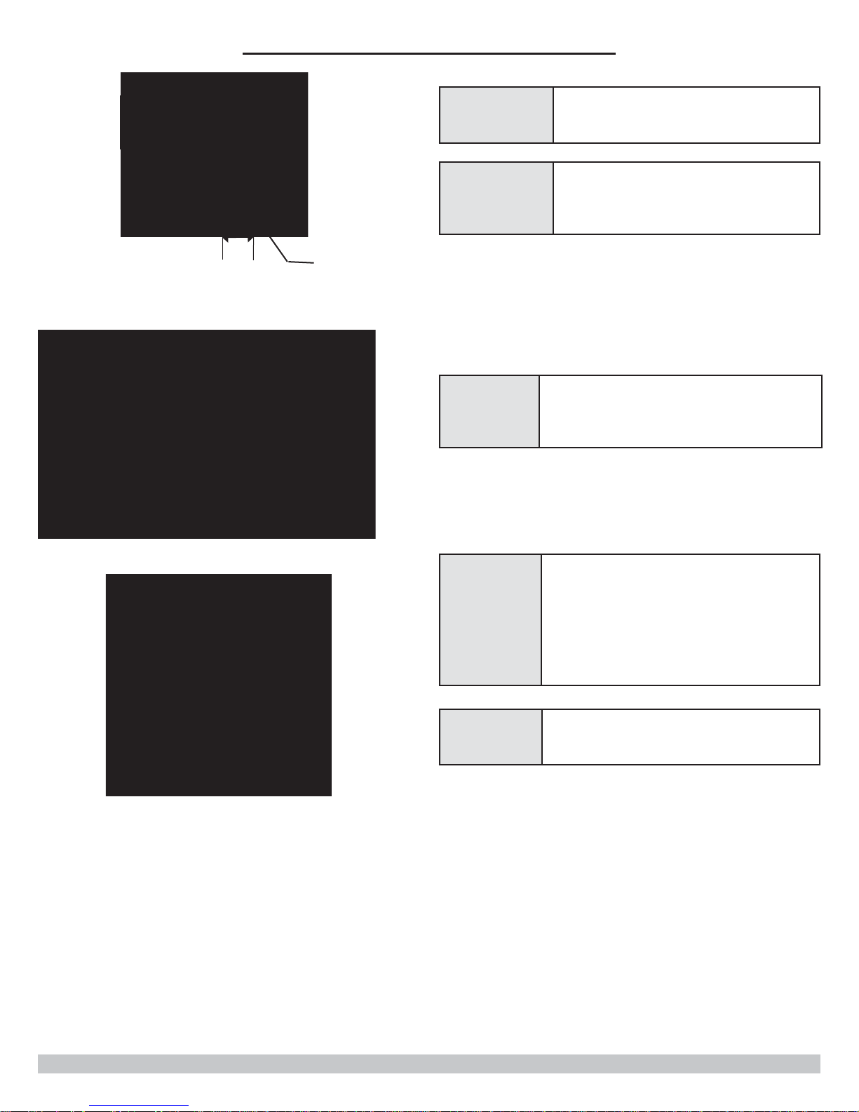
6 - COMBUSTION AIR AND VENT PIPING
Forced Air
Inlet
12"'
(30.5cm m)
Minimum
Less than
10' (3 m)
Minimum
Termination must
be 12" (30.5 cm)
from or below doors,
windows or gravity
inlet.
Termination
Termination
3' (0.9 m)
[If located
within 10' (3 m)
of forced air
inlet]
Doors &
Windows
Condensate
Forced Air
Inlet
Combustion air and vent termination
must be 12" (30.5 cm) from or below
doors, windows or gravity inlet.
Vent gas may condense, forming
moisture, may be corrosive. Protect
building materials at vent from exhaust
of vent gas.
Terminate venting system 3’ (0.9 m)
above and 10' (3.0 m) from any forced
air inlet (except boiler’s combustion air
inlet).
3' (0.9 m)
Minimum
Grade,
Snow & Ice
"L"
Corner
Terminate vent bottom, min. 12"(300
mm) above highest anticipated snow
level.
Avoid locations where snow may drift and
block vent. Ice or snow may cause boiler
to shut down if vent becomes obstructed.
Vent termination shall NO T be installed
closer than 3' (0.9 m) from inside corner
of “L” shaped structure.
22
Page 23
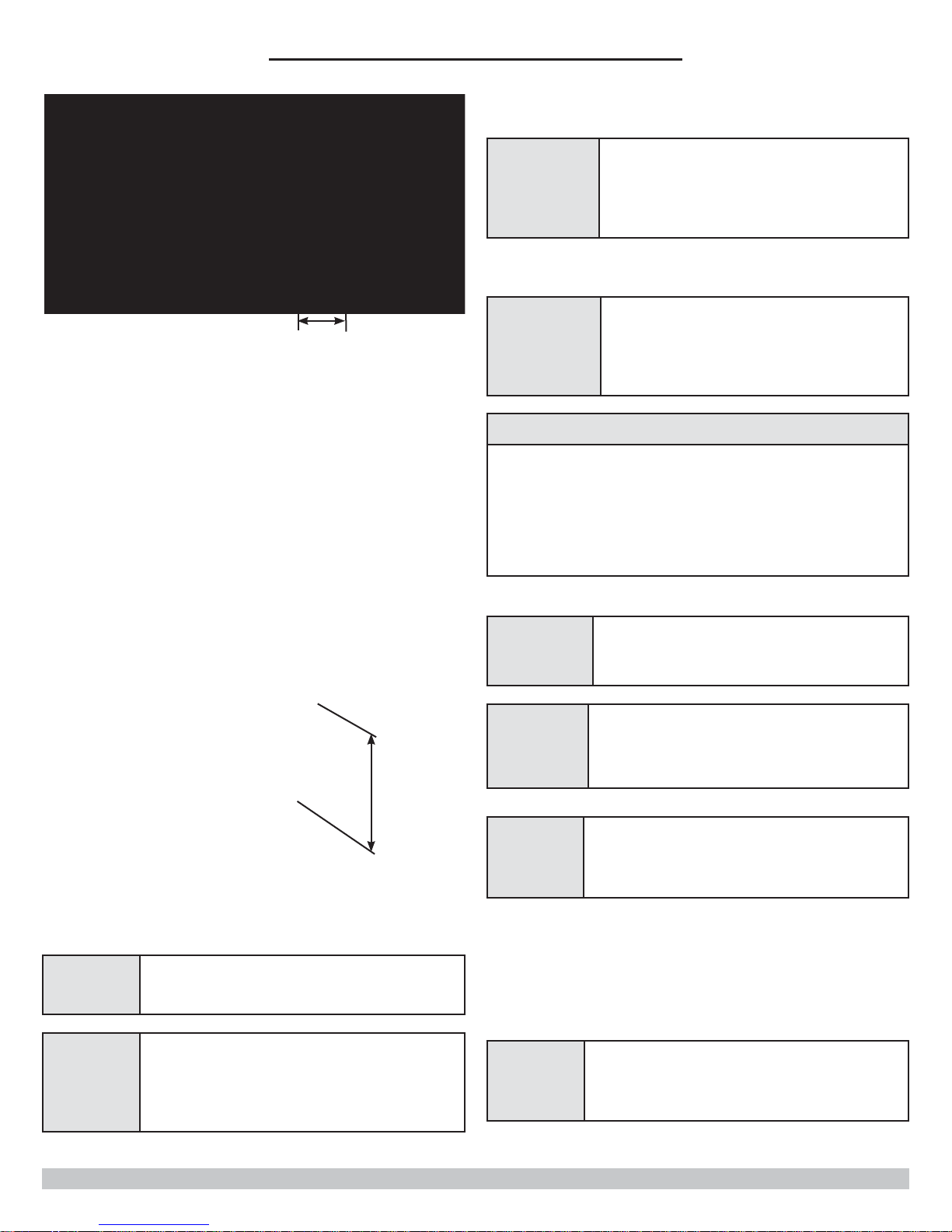
6 - COMBUSTION AIR AND VENT PIPING
Keep vent termination 3’min. (0.9
3' (0.9 cm)
Minimum
Vegetation,
Plants &
Shrubs
Termination
Meters,
Regulators,
deck, porch
Requirements for Commonwealth of Massachusetts
Boiler and venting installation must conform to state code
248 CMR which includes but is not limited to:
Installation by licensed plumber or gas fi tter.•
cm) away from vegetation. Position
termination where vent vapors will not
damage plants/shrubs or air conditioning
equipment.
Vent termination 4’ (1.2 m) horizontally
from, no case above or below, electric meters, gas meters, regulators,
and relief equipment, or under deck or
porch.
Vapors
7' (2.1 m)
Minimum
Position termination where vent vapors are
not objectionable.
Carbon monoxide detectors with side wall horizontally •
vented gas-fuel equipment in residential dwelling,
building or structure.
Locate vent termination minimum 7'
Walkways
People or
Pets
Stones,
Balls,
Etc.
(2.1 m) above any public walkway, with
consideration to condensate.
Locate combustion air and vent termination
to prevent accidental contact with people
or pets.
Position combustion air and vent
termination where it will NOT be damaged
by foreign objects, such as stones, balls,
etc.
Position termination so it will not be effect-
Eddy,
Flue
Gases
ed by wind eddy, air born leaves, snow, or
recirculated vent gases. Give consideration
to excessive wind and locate away from
windward side of building.
Multiple
Family
Dwellings
23
Vent shall not terminate directly above
paved sidewalk or paved driveway located
between two single-family dwellings serving
both dwellings.
Page 24
6 - COMBUSTION AIR AND VENT PIPING
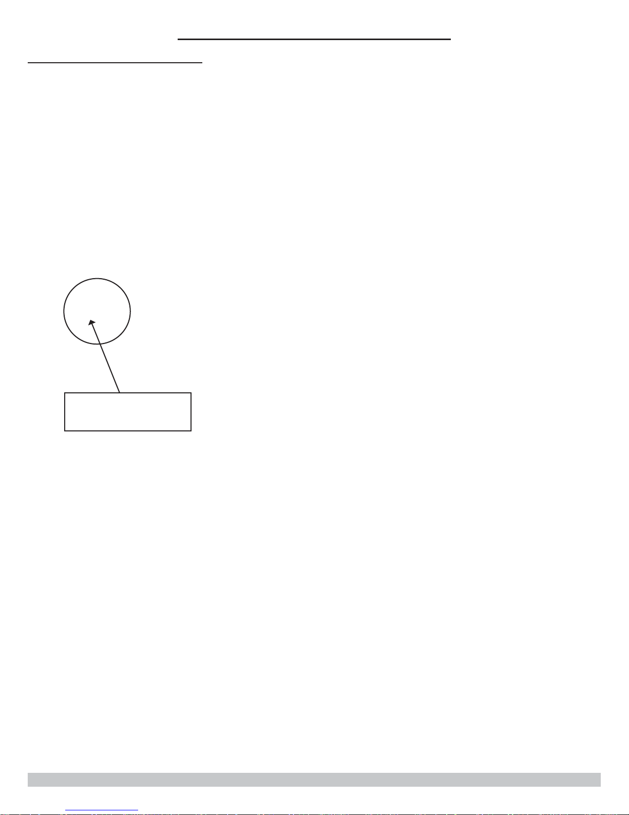
FIGURE 6-1 Condensate Drain
6.6 Condensate Piping
Use materials acceptable to authority having jurisdiction. •
In absence of such authority:
USA - PVC or CPVC per ASTM D1785/D2845 Cement •
or primer per ASME D2564 or F493.
Canada - CSA or ULC certifi ed PVC/CPVC pipe, fi t-•
tings and cement.
Insert 1/2" (1.3 cm) PVC pipe through grommet in •
chassis.
Attach PVC tee provided with boiler and fi eld sourced •
piping to condensate drain stub on left side of boiler.
See fi gure 6-1.
Slope condensate drain pipe minimum 1/4" per foot •
(21mm/m) away from boiler.
Use condensate pump if boiler located below disposal •
point. 120 VAC auxiliary power outlet can be used to
power condensate pump.
Field source condensate neutralizing fi lter as required •
by authority having jurisdiction or for environmentally
friendly condensate disposal.
PVC Tee (fi eld installed)
on condensate drain
stub
24
Page 25
!
7 - GAS SUPPLY PIPING
7-1 Gas Connection Knockout Plate at Bottom of
Boiler
Bottom knock out
for Optional Gas
Connection
7.1 General
7-2 Gas connection at Top of Boiler
Gas Connection Top
of Boiler
!
CAUTION
WHAT TO DO IF YOU SMELL GAS
Do not try to light any appliance.•
Do not touch any electrical switches; do not use •
any phones in your building.
Immediately call your gas supplier from a neigh-•
bor’s phone.
Follow the gas supplier’s instructions. •
If you cannot reach your gas supplier, call the fi re •
department
Use piping materials and joining methods acceptable •
to authority having jurisdiction. In absence of such
requirements:
USA - National Fuel gas Code, ANSI Z223.1/NFPA 54•
Canada - Natural Gas and Propane Installation Code, •
CAN/CSA B149.1)
Size and install gas piping system to provide suffi cient •
gas supply to meet maximum input at not less than
minimum supply pressure. See Table 5.
Support piping with hooks, straps, bands, brackets, •
hangers, or building structure components to prevent or
dampen excessive vibrations and prevent strain on gas
connection. Boiler will not support piping weight.
Use thread (joint) compound (pipe dope) suitable for •
liquefi ed petroleum gas.
7-3 Bottom Gas Connection
Optional Bottom Gas
Connection
SIZE
075 75,000
100 100,000
Note: See Piping Table 16-Glossary page 58
Maximum
Input (Btuh)
7.2 Near Boiler Gas Piping
Select top or bottom gas connection. To convert from
•
top connection to bottom connection:
Remove bottom knockout by removing two (2)
•
screws. See fi gure 7-1.
Disconnect gas connection by removing two (2)
•
screws. See fi gure 7-2.
Relocate gas connection to bottom opening.
•
Secure with two (2) screws. See fi gure 7-3.
Relocate knockout cover to top opening. Secure
•
with two (2) screws. See fi gure 7-4.
Install fi eld sourced manual main shutoff valve and
•
ground joint union. See fi gure 7-5.
TABLE 5: GAS SUPPLY PRESSURE
Natural Gas Propane
Min. Max. Min. Max.
3.0" w.c.
(0.7 kPa)
3.0" w.c.
(0.7 kPa)
13.5" w.c.
(3.3 kPa)
13.5" w.c.
(3.3 kPa)
5.0" w.c.
(1.2 kPa)
5.0" w.c.
(1.2 kPa)
13.5" w.c.
(3.4 kPa)
13.5" w.c.
(3.4 kPa)
25
Page 26
7 - GAS SUPPLY PIPING
!
DANGER
Fire Hazard. Do not use matches, candles, open
fl ames, or other methods providing ignition source.
Failure to comply will result in death or serious
injury.
7.3 Leak Check Gas Piping
Pressure test boiler and gas connection before placing
boiler in operation.
Pressure test over 1/2 psig (3.5 kPa). Disconnect
•
boiler and its individual gas shutoff valve from
gas supply system.
Pressure test at 1/2 psig (3.5 =kPa) or less.
•
Isolate boiler from gas supply system by closing
manual gas shutoff valve. See fi gure 7-6.
Locate leakage using gas detector, noncorrosive
•
detection fl uid, or other leak detection method
acceptable to authority having jurisdiction. Do
not use matches, candles, open fl ames, or other
methods providing ignition source.
Correct leaks immediately and retest.
•
7-4 Gas Connection Knockout Plate at Top of
Boiler
Top of Boiler knock out
for Gas Connection
7-5 Manual Main Gas Shutoff Valve Outside
Boiler Jacket
Manual Main Gas
Shutoff Valve
Option: Gas
Connection May be
Located
At Bottom of Boiler
7-6 Gas Shutoff Valve
Gas shutoff valve
(shown in closed
position)
26
Page 27
8 - ELECTRICAL CONNECTIONS
!
WARNING
Electrical shock hazard. Turn OFF electrical power
supply at service panel before making electrical
connections. Failure to do so could result in death
or serious injury.
NOTICE
Wiring diagrams can be found in Section 15 of this
Manual.
8-1 LINE VOLTAGE CONNECTIONS
8-2 LOW VOLTAGE CONNECTIONS
8.1 General
Electrically bond boiler to ground in accordance with requirements of authority having jurisdiction. In absence of
such requirements:
USA- National Electrical Code, ANSI/NFPA 70.•
Canada - Canadian Electrical Code, Part I, CSA C22.1: •
Safety Standard for Electrical Installations.
8.2 Line Voltage Connections (Figure 8-1)
Boiler•
Provide individual 120V, 15 amp circuit (recom-A.
mended) with fused disconnect or service switch,
as required by authority having jurisdiction.
Open High Voltage Junction Box (see Figures 3-1, B.
3-2) to access line voltage terminal strip.
Connect 120 VAC circuit to line voltage terminal C.
strip 120 VAC L,N,G.
Central Heating Pump, if used.•
Isolate pump from control module if pump FLA A.
exceeds 5 amps.
Connect pump to line voltage terminal strip CH B.
PUMP L,N,G.
Domestic Hot Water Pump, if used.•
Isolate pump from control module if pump FLA A.
exceeds 0.5 amps.
Connect pump to line voltage terminal strip DHW B.
PUMP L,N,G.
8.3 Low Voltage Connections (Figure 8-2)
User Interface Terminals •
Factory wired to low voltage terminal plug USER A.
INTERFACE terminals
Optional - Remote mount user interface for im-B.
proved access. See Controller Manual for additional
information.
Argus Link (Multiple boiler applications only)•
Outdoor Sensor, if used.•
Provided with boiler in accessory kit.A.
Locate outdoor sensor to protect against wind and B.
direct sunlight. Mounting instructions provided with
sensor.
Maximum wire length is 100 ft (30m) for 22 ga. C.
wire, or 150 ft (45m) for 18 ga. wire.
Connect wires to low voltage terminal plug OUT-D.
DOOR SENSOR terminals. Wires are interchangeable.
System Sensor •
When using system sensor with multiple boiler A.
applications, connect sensor wires to low voltage
terminal plug SYSTEM SENSOR terminals. Wires are
interchangeable.
27
Page 28

8 - ELECTRICAL CONNECTIONS
Domestic Hot Water (DHW) Thermostat, if used.•
Use Temperature control with dry contacts rated at A.
0.5 amps @ 120 VAC. Boiler control does not provide power to DHW temperature control
Maximum wire length is 330 ft (180 m) 22 gauge B.
wire.
Connect wires (interchangeable) to low voltage C.
terminal plug DHW T-T terminals. Wires are
interchangeable.
Use of isolation relay is required. Do not use control D.
with 24 VAC circuit typically found on zone t-stat
terminal.
Central Heating Thermostat•
Use thermostat or boiler system control with dry A.
contacts related 0.5 amps @ 120 VAC. Boiler
control does not provide 24 VAC power to central
heating thermostat.
Locate and install thermostat per manufacturer's B.
instructions and away from infl
hot or cold water pipes, light fi xtures, televisions,
sunlight, or fi replaces.
Maximum wire length isC. 330 ft (180 m) for 18 ga.
wire.
Connect wires to low voltage terminal plug CH T-T D.
terminals. Wires are interchangeable.
uences of drafts,
28
Page 29
9 - START UP PROCEDURE
NOTICE
IMPORTANT: On initial start up condensate trap
must be manually fi lled with water.
9-1 Condensate Drain Assembly
9.1 Fill boiler with water and purge air
Consult local water treatment companies for hard water •
areas (above 7 grains hardness).
Do not fi ll boiler or operate with water containing chlorine •
in excess of 200ppm. Filling with chlorinated fresh tap
water should be acceptable.
Fill boiler and system piping with water (or antifreeze-
•
water solution, if used). See antifreeze information
page 12. Purge air from boiler using air vent. Purge
air from system piping.
Inspect system piping and boiler connections. Repair
•
any leaks immediately.
9.2 Fill Condensate Trap with Water
Disconnect collet clip from elbow. See fi gure 9-1.
•
Disconnect tubing below elbow.
•
Pour about 1 cup (237ml) of water into vent drain.
•
•
Reconnect tubing to elbow with collet clip. See Figure
•
9-1.
1. Disconnect collet clip from
hose barb and fi ll Condensate
trap with water.
2. Reconnect collet clip to hose barb
before starting boiler.
29
Page 30
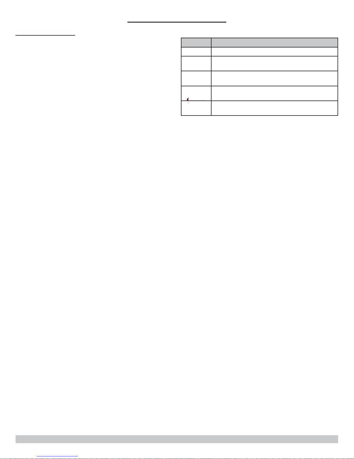
9-2 User Interface
e
-2 User Interfac
9 - START UP PROCEDURE
9.3 Program Boiler Control
Key Description
- Manual Lockout Reset
- Enter/Exit user menu
- Go to previous screen
- Select a menu item
- Confi rm new parameter value
- Scroll up to next menu item
- Increase value
- Scroll down to next menu item
- Decrease value
Verify thermostat is off or in set to cooling mode.1.
Turn power switch to ON position.2.
Set language: default English3.
Press Menu [M]
•
Use arrow keys to scroll to • Settings; press OK
once
Use arrow keys to scroll to • Language
Press OK key once (choices start blinking)
•
Use arrow keys to scroll to desired Language
•
Press OK key once
•
4. Set Temperature Scale: default Fahrenheit
Use arrow keys to scroll to • Change
Temperature units
Press OK key once (units start blinking)
•
Use arrow keys to scroll to desired scale
•
Press OK key once
•
Press Menu once to return to main menu
•
Installer Menu5. - press both OK and Menu keys at
same time - hold down for 4 seconds.
Press arrow keys to scroll to • Boiler Confi g.
Press arrow keys to scroll to • Pump mode
Press OK key once
•
2 choices:
•
Pump Mode 0 : CH
A.
Pump Mode 1: CH & DHW
B.
Press OK key once
•
30
Use arrow keys to scroll to • SERVICE REMINDER
Press OK key once
A.
Use arrow keys to scroll to choice: ON or
B.
OFF
Press OK key once
C.
If ON use arrow keys to scroll to desired
D.
time for service reminder
Page 31

9 - START UP PROCEDURE
Press OK key once
E.
Press Menu key once
F.
Press arrow keys to scroll to • CH (Central
Heating) SETTINGS
A.
Press OK key once
In CH Mode:
B.
Press OK key once
C.
4 modes to choose from, scroll to
D.
choice:
0 - No outdoor reset
1 - Outdoor reset (Default mode)
2 - Full outdoor reset - No thermostat
3 - CH with permanent demand
Press OK key once
•
Use arrow keys to scroll to • WARM WEATHER
SHUT DOWN TEMP. Down Temp. - default is
70°F (21°C)
Press OK key once
A.
Scroll to temperature choice
B.
Press OK key once
C.
Use arrow keys to scroll to • RESET CURVE design
temperatures. Default is 180°F (82°C) Boiler
temperature, 0°F (-18°C) Outdoor temperature.
Press OK key once
A.
Scroll to temperature choice
B.
Press OK key once
C.
Use arrow keys to scroll to • R.CURVE MILD
WEATH. Default is 70°F (21°C) Boiler, 70 °F
(21°) Outdoor. To change:
Press OK key once
A.
Scroll to temperature choice boiler
B.
Press OK key once
C.
Use arrow keys to scroll to • BOOST function,
default Temperature is 18°F, Time 20 minutes.
To change:
Press OK key once
A.
Scroll to temperature choice
B.
Press OK key once; scroll to select Time
C.
Scroll to time choice
D.
Press OK key once
E.
Use arrow keys to scroll to• MAXIMUM POWER
CH, default is 100%. To change:
Press OK key once
A.
Scroll to power choice
B.
Press OK key once
C.
Press Menu key once
•
In DHW mode • (DHW setting is for tank tem-
perature)
Press OK key once
A.
3modes to choose from
B.
0 - No DHW
1 - DHW store with sensor
2 - DHW setting is for tank temperature
Press OK key once
•
Use arrow keys to scroll to • DHW MAXIMUM
PRIORITY TIME, default is 30 minutes.
Press OK key once
A.
Scroll to Time choice
B.
Press OK key once
C.
Press Menu key twice will take you back to regu-
•
lar menu.
6.
System Test Mode
The installer menu also features a 'System Test' mode
which allows the contractor to test proper operation of
the combustion system and the pumps.
Combustion Check:
•
Use arrow keys scroll to System Test
A.
Menu
Press OK key once
B.
Use arrow keys scroll to 'System Test
C.
Power' menu
Press OK Key once
D.
3 selections to choose from
E.
0 - Low
2 - Ignition
3 - High
4 - Off
Press OK key once
F.
Note: In test mode boiler will stay at fi xed fi ring
rate until either 30 minutes elapses, user
switches to 'OFF' mode or boiler reaches
maximum temperature.
Pump Check:
•
Use arrow keys scroll to System Test
A.
Menu
Press OK key once
B.
Use arrow keys scroll to 'Pump' menu
C.
Press OK Key once
D.
Scroll to Boiler, CH/System or DHW to
E.
cycle Press OK key on choice
Pumps will shutoff after 6 minutes
F.
Cascade Settings 7. - See ECR Multiple Boiler Manual
Use arrow keys to scroll to • DHW Settings
31
Page 32
9 - START UP PROCEDURE
9.4 Boiler Start-up and Operational Test
Verify air is purged from hydronic piping1.
System test pumps - verify each pump is opera-2.
tional
Verify gas piping3.
Confi rm pressure test. See section 7.3.
•
Visually inspect piping to determine there are no
•
open fi ttings or ends, and all valves at unused
outlets are closed and plugged/capped.
Purge air from piping
•
Check piping and connections for leaks immedi-
•
ately after gas is turned on. Shut off gas supply
and make necessary repairs if leaks found.
Follow OPERATING INSTRUCTIONS to initiate boiler 4.
operation. See section 10.
Inspect combustion air and vent piping. Verify pipe 5.
is not leaking and terminations are unobstructed
and vent gas discharge is not a nuisance or hazard.
Verify boiler functions.6.
Inspect condensate disposal system. Verify con-7.
densate fl ows adequately and is disposed properly.
Check control module operation.8.
Check fi eld-sourced limits, low water cutoffs, etc. 9.
per manufacturer's instructions.
Compare to boiler rating2.
Size Minimum Nominal Maximum
075 68.0 75.0 77
100 90.0 100.0 103
Adjust rate if needed using diagram 9-3 below3.
Check CO4.
. Natural gas should be between 8.5%
2
and 10.0%.
If CO
•
is low increase gas fl ow following diagram
2
9-3 below.
If CO
•
is high decrease gas following diagram
2
9-3 below.
Propane Gas
Most propane systems do not have fl ow meters.
Check CO1.
. Propane should be between 9.5% and
2
11.0%.
If CO
•
is low increase gas fl ow following diagram
2
9-3 below.
If CO
•
is high decrease gas fl ow following dia-
2
gram 9-3.
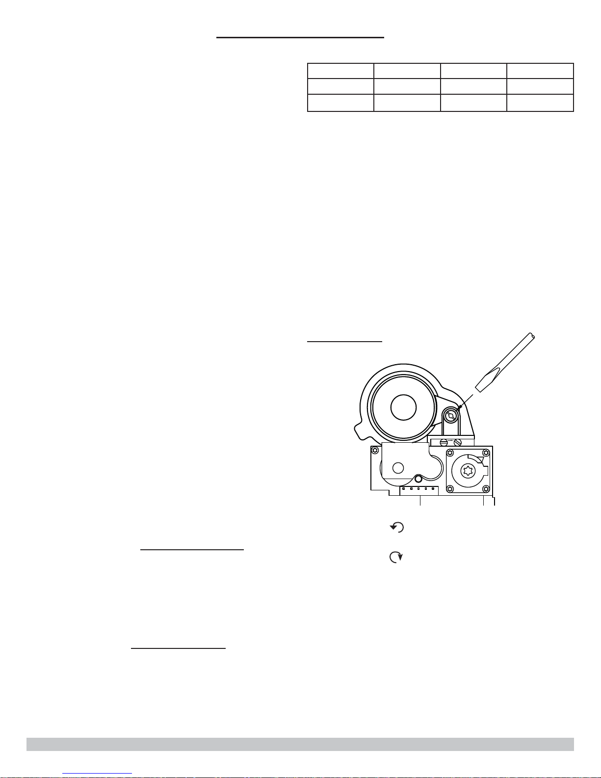
9-3 Gas Valve
1/4" FLAT HEAD
SCREWDRIVER
9.5 Check Combustion
Natural Gas
Measure input. English units*1.
Turn off gas to all other appliances.
•
Use ½, 1 or 2 cu ft dial on gas meter. Mea-
•
sure time required for one or more complete
revolutions. Measure time for 1-2 minutes.
Calculate input.
•
Input (MBH) =
Example: Gas fl ow from
Meter = 2 cu ft
Measured time = 72 seconds
Rate ( MBH) =
3600 x cu ft
seconds
3600 x 2 cu ft
72 seconds
=
100
MBH
MIN
To increase gas fl ow turn 'throttle' left or counter
•
OUT
clockwise .
To decrease gas fl ow turn 'throttle' right or
•
clockwise .
Limit adjustment to one turn and retest.
•
*See Metric - Glossary page 58
32
Page 33
9 - START UP PROCEDURE
NOTICE
Combustion analyzer port is provided. After use
replace cover.
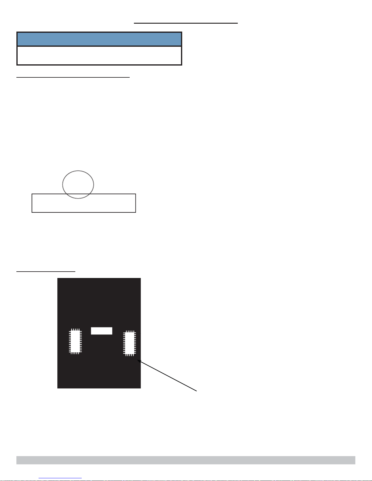
9-4 Combustion Air Analyzer Port
Combustion Air Analyzer Port
Verify Burner, Proper Operation
Inspect burner fl ame through Sight Glass. See fi g-1.
ure 9-5.
Operate boiler through several heating cycles, 2.
including domestic hot water, if used. Verify proper
operation.
Reset control parameters to operating settings if
3.
adjusted to allow startup and operation test.
Follow instructions TO TURN OFF GAS TO APPLIANCE 4.
if boiler is not being placed into immediate operation.
Enter installer information on Warranty Registration 5.
Card.
Gather all instructions, manuals, wiring diagrams, 6.
warranty registration card and other supporting
information. Review with user and/or affi x in con-
spicuous location adjacent to boiler.
9-5 Burner Flame
Burner
Flame
Flame
Look for BLUE fl ame
with slight YELLOW tips
evenly spaced around
the burner
33
Page 34
!
10 - OPERATING INSTRUCTIONS
FOR YOUR SAFETY READ BEFORE OPERATING
!
WARNING
If you do not follow these instructions
exactly, a fi re or explosion may result
causing property damage, personal injury
or loss of life.
This appliance is equipped with an ignition device •
which automatically lights burner. Do NOT try to
light this burner by hand.
Before operating smell all around appliance area •
for gas. Be sure to smell next to fl oor because
some gas is heavier than air and will settle to the
fl oor.
Use only your hand to turn the gas shutoff •
valve. Never use tools. If valve will not turn by
hand, do not try to repair it, call a qualifi ed ser-
vice technician. Force or attempted repair may
result in fi re or explosion.
Do not use this appliance if any part has •
been under water. Immediately call a quali-
fi ed service technician to inspect appliance and to
replace any part of control system and any gas
control which has been under water.
!
CAUTION
WHAT TO DO IF YOU SMELL GAS
Do not try to light any appliance.•
Do not touch any electrical switches; do not use •
any phone in your building.
Immediately call your gas supplier from a neigh-•
bor’s phone. Follow the gas supplier’s instructions.
If you cannot reach your gas supplier, call the fi re •
department.
10.2 TO TURN OFF GAS TO APPLIANCE
Set thermostat to lowest setting.•
Turn• "OFF" all electric power to appliance if service is
to be performed.
Remove front jacket panel.•
Turn gas shutoff valve handle should be clockwise •
to closed position. Handle should be perpendicular to
gas pipe.
Replace front jacket panel.•
10-1 Gas Shutoff Valve
10.1 OPERATING INSTRUCTIONS
Stop! Read Safety information above.
Set thermostat to the lowest setting.•
Turn "• OFF" all electrical power to appliance.
This appliance is equipped with an ignition device which •
automatically lights the burner. Do not try to light
this burner by hand!
Remove the front jacket panel.•
Turn• gas shutoff valve clockwise to closed position.
Handle should be perpendicular to gas pipe.
Wait 5 minutes for any gas to clear. Smell for gas, •
including near fl oor. If you smell gas, STOP! Follow
instructions on this page: “What To Do If You Smell
Gas.” If you do not smell gas, go to next step.
Turn gas shutoff valve counter clockwise to the •
open position. Handle should be parallel to gas pipe.
Replace front jacket panel.•
Turn "• ON" electrical power to appliance.
Set thermostat to desired setting.•
If the appliance will not operate, follow instructions TO •
TURN OFF GAS TO APPLIANCE and call your service
technician or gas supplier.
OPEN POSITION
CLOSED POSITION
34
Page 35
11 - GENERAL MAINTENANCE AND CLEANING
!
!
DANGER
Before servicing, turn off electrical power to boiler
at service switch. Close manual gas valve to turn
gas supply OFF to boiler.
!
CAUTION
Label all wires prior to disconnection when servicing controls. Wiring errors can cause improper and
dangerous operation.
NOTICE
Verify proper operation after servicing.
NOTICE
Perform regular service and maintenance by
qualifi ed service agency at least once every 12
months to assure safe, trouble free operation
and maximum effi ciency .
11-1 Sight Glass
11.1 Beginning of Each Heating Season
Check boiler area is free from combustible materials, •
gasoline, and other fl ammable vapors and liquids.
Visually inspect combustion air and vent piping for proper •
operation. Check for and remove any obstruction to fl ow
of combustion air or vent gases. Immediately repair or
replace pipe showing deterioration or leakage. Insure
proper reassembly and resealing of system.
Visually inspect condensate drain line for proper opera-•
tion. Checking for deteriorated or plugged condensate
drain line. Verify condensate trap drains freely.
Test safety relief valve for proper operation. Refer to •
valve manufacturer's instructions packaged with relief
valve.
Examine fl ue passages in heat exchanger, burner, con-•
densate lines, and cleaning (if necessary) by following
instructions in “Annual Examination and Cleaning of Boiler
Components” in this section.
Circulator pump and blower fan motor furnished with boil-•
er are permanently lubricated from factory and require
no further lubrication. Lubricate fi eld sourced pumps and/
or motors should be lubricated according to pump and/or
motor manufacturer’s instruction.
Check following components are operating properly and •
are free of blockages or obstructions:
Sight Glass
air vent;•
check venturi air inlet for blockage and clean as re-•
quired;
check air hose is tight•
supply, return, and fl ue temperature sensor clips •
must be securely seated on pipes; Check boiler for
any sign of leaks.
Check low water cutoff using user interface.•
Check operation every year by pressing test button.•
"Low Water" LED should illuminate and burner •
should shut down.
Every 5 years remove Low water cutoff and clean •
all surfaces in contact with water. Reinstall after
cleaning.
Every 10 years replace low water cutoff.•
Check fl ame signal with user interface. Should be 8 micro •
amps at high fi re.
35
Page 36
11 - GENERAL MAINTENANCE AND CLEANING
Visual inspection of fl ame through sight glass. Burner •
should be fully illuminated.
Check expansion tank.•
11.2 Annual shut down procedure
Follow instructions “To Turn Off Gas To Appliance”• unless
boiler is also used to supply domestic hot water. See
section 10.
Drain system completely and add antifreeze when heat-•
ing system is to remain out of service during freezing
weather.
Drain condensate lines when boiler is to be exposed to •
freezing temperatures.
!
DANGER
Before servicing, turn off electrical power to boiler
at service switch. Close manual gas valve to turn
OFF gas supply to boiler.
11-2 Blower Inlet Assembly
A
B
C
D
E
F
G
!
WARNING
The following service procedures must be performed
by qualifi ed service agent. Boiler owner shall not at-
tempt these steps.
11.3 Annual Examination and Cleaning of Boiler
Components
Obtain Burner Inspection Kit. See parts list.•
Before servicing, turn off electrical power to boiler at •
service switch.
Follow instruction 'To Turn Off Gas to Appliance'. Close •
main gas valve.
Visually inspect through sight glass no fl ame is present.•
Examine fl ue passages by removing blower/burner as-•
sembly from heat exchanger.
Confi rm manual gas valve is closed. Disconnect gas •
line to gas valve at union. Disconnect air hoses to gas
valve and air inlet.
Disconnect wires to gas valve, fl ame rod sensor and •
igniter.
H
I
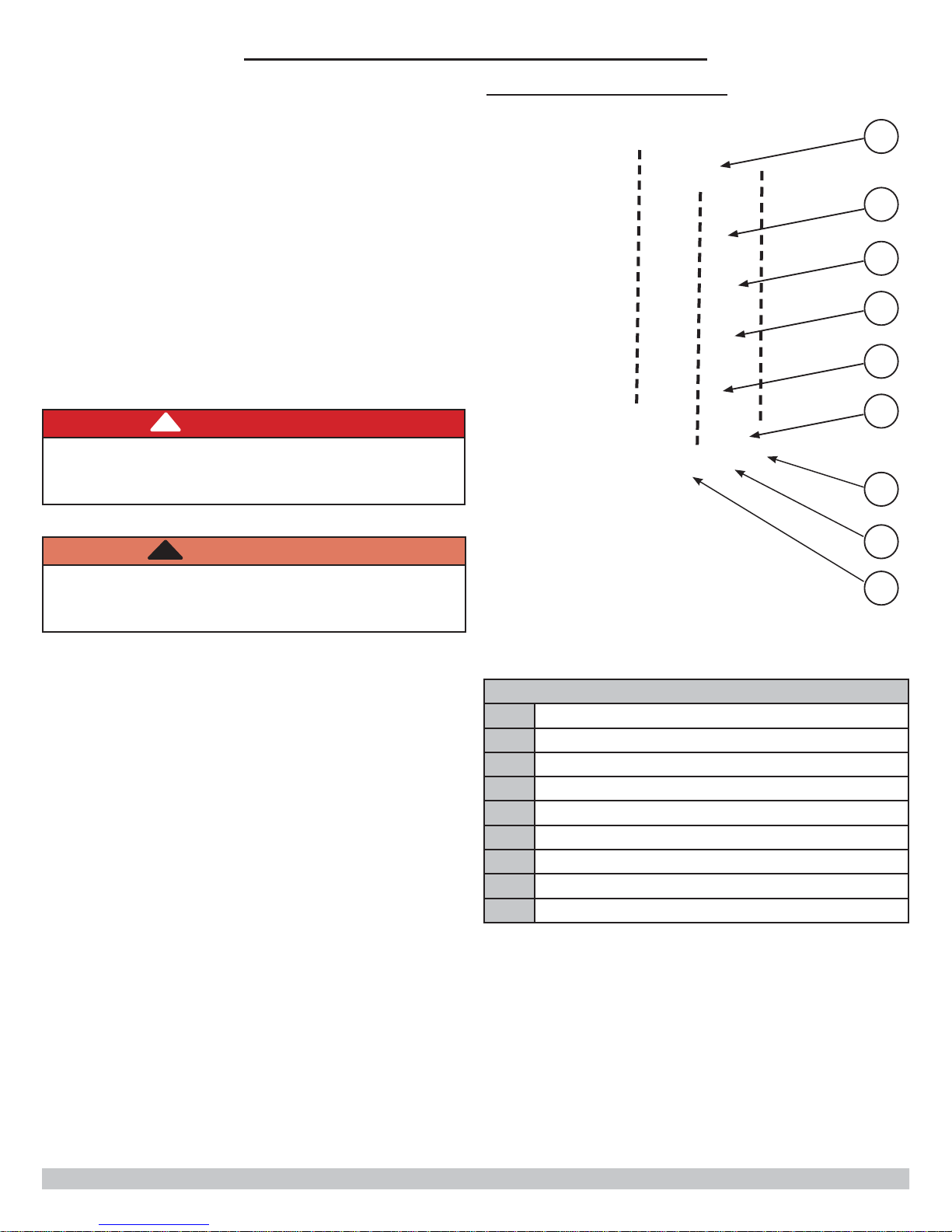
Burner Assembly
A Fuel Mixer
B Burner Gasket - Upper
C Burner Plate
D Refractory
E Burner
F Burner Gasket - Lower
G Flame Sensor
H Igniter
I Sight Glass
Remove 2 screws and carefully remove igniter.•
Remove 2 screws and carefully remove fl ame rod •
sensor.
Loosen and remove four nuts connecting blower inlet •
assembly to heat exchanger.
36
Page 37
11 - GENERAL MAINTENANCE AND CLEANING
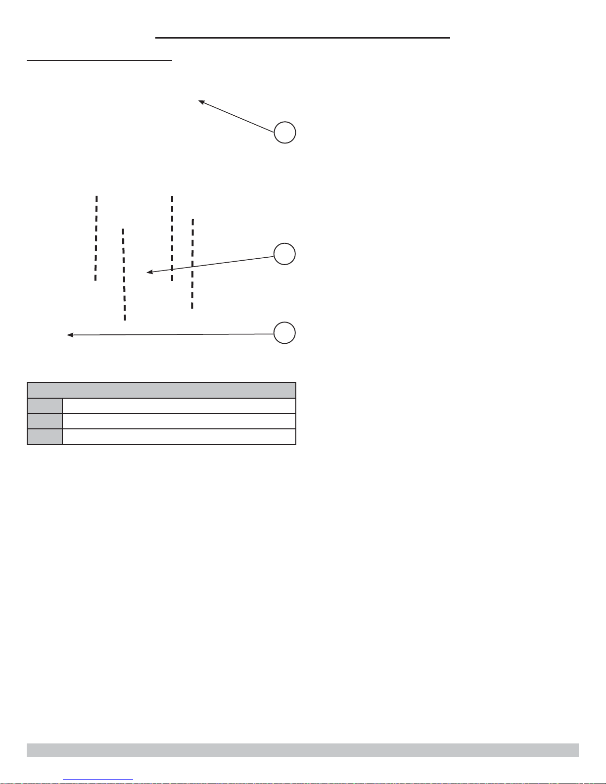
11-2 Condensate Collector
Condensate Collector
A Combustion Chamber
B Condensate Collector
C Condensate Drain
Remove inlet assembly with blower attached, remove •
gasket and burner.
Clean burner by inserting an air hose into blower •
opening of casting and blowing air through heat
exchanger side.
A
B
C
After cleaning burner, remove burner holder and •
refractory from top of combustion chamber. Remove
four nuts holding condensate collector from bottom of
heat exchanger assembly. Also remove gasket.
Clean heat exchanger with low pressure water spray. •
If this does not clean fi ns adequately, use fl exible
handle nylon brush to loosen sediment and oxide on
all accessible heating surfaces of heat exchanger.
Take care not to get brush stuck in heat exchanger.
After brushing and rinsing, remove any remaining •
loosened sediment using shop vacuum with snorkel attachment. Inspect burner for foreign matter in
fl ame ports or inside burner. Foreign matter should
be removed by blowing with compressed air or
vacuuming. If burner cannot be cleaned, it must be
replaced.
Reinstall refractory, burner holder, burner and re-•
place gasket (in that order). Position blower adapter
assembly over studs. Install four nuts and tighten.
Reinstall igniter and igniter gasket and fasten with
two screws. Replace gasket and condensate collector
to bottom of heat exchanger assembly. Replace and
tighten four nuts holding collector to heat exchanger
assembly.
Connect gas line to gas valve, pressure switch hose •
to gas valve and air inlet assembly, igniter wires, and
gas valve wires.
Visually inspect condensate trap. Any foreign material •
visible in condensate lines need to be cleaned out as
described below:
I• nspect for sediment or blockage.
Flush out with water or vacuum.•
Follow the instructions “Filling The Condensate Trap •
With Water”
Follow Boiler Start-up and Operational Test. See section •
9.4.
Page 29
.
37
Page 38
12 - RATINGS AND CAPACITIES
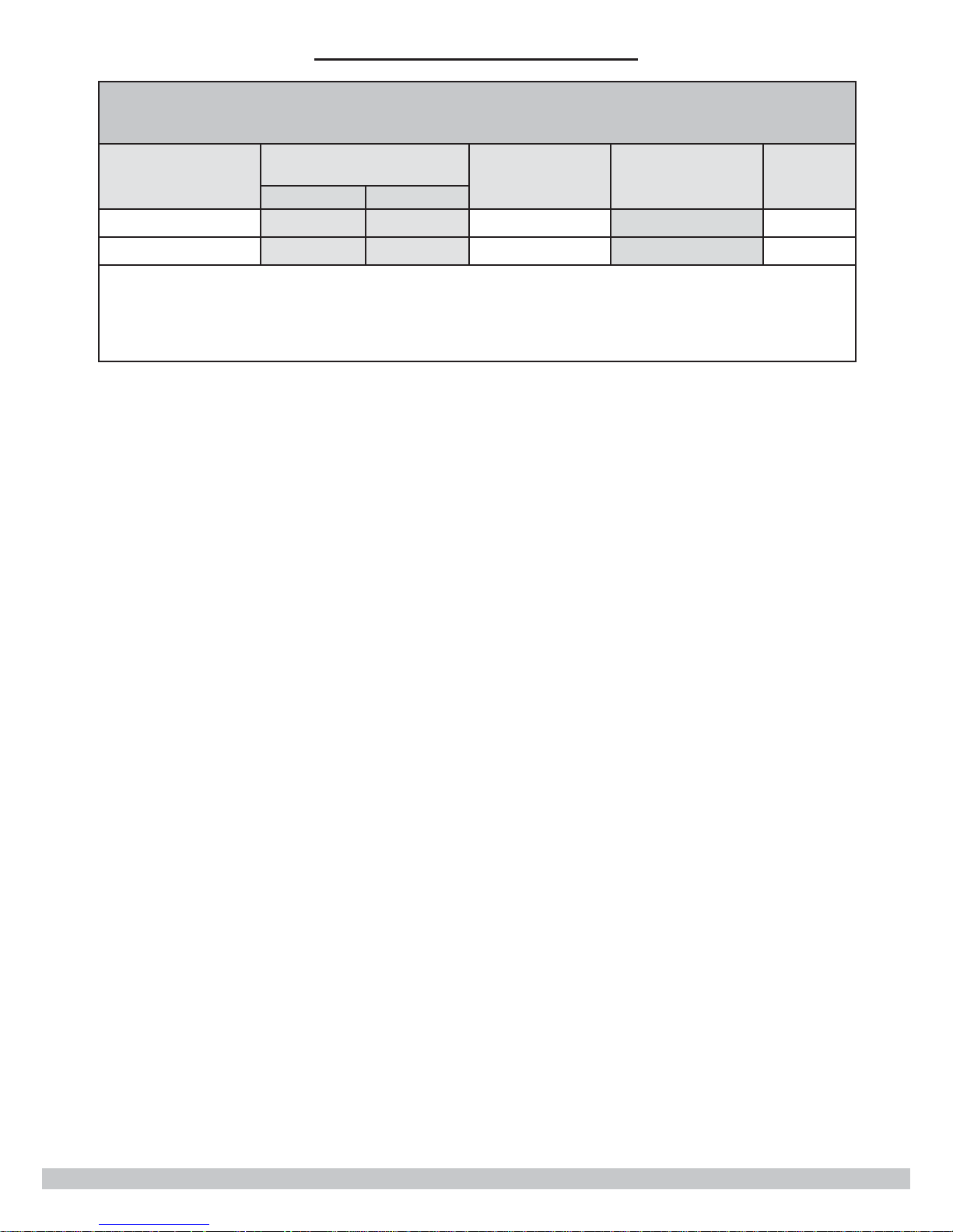
TABLE 12-1: SEA LEVEL RATINGS
NATURAL AND PROPANE GASES
Size
075
100
(1)
1000 Btu/hr (British Thermal Units Per Hour)
(2)
Heating Capacity and AFUE (Annual Fuel Utilization Effi ciency) are based on DOE (Department of Energy) test
procedures.
(3)
Net I=B=R Ratings based on piping and pickup allowance of 1.15. Contact ECR Technical Support before selecting boiler for
installations having unusual piping and pickup requirements, such as intermittent system operation, extensive piping systems,
etc..
Boiler Input Rate (MBH)
Maximum Minimum
75 15 69 60 97.0
100 20 91 79 97.0
(1)
12.1 Ratings and Capacities
Constructed and hydrostatically tested for maximum •
working pressure of 50 psig (pounds per square inch
gauge) in accordance with ASME Boiler and Pressure
Vessel Code, Section IV, Rules for Construction of
Heating Boilers.
Ratings are for sea level applications. Boiler •
derates input 2% for every 1000 feet above an elevation
of 2000 feet.
Heating Capacity
(MBH)
(1)(2)
Net I=B=R Rating,
Water (MBH)
(1)(3)
AFUE
(2)
38
Page 39
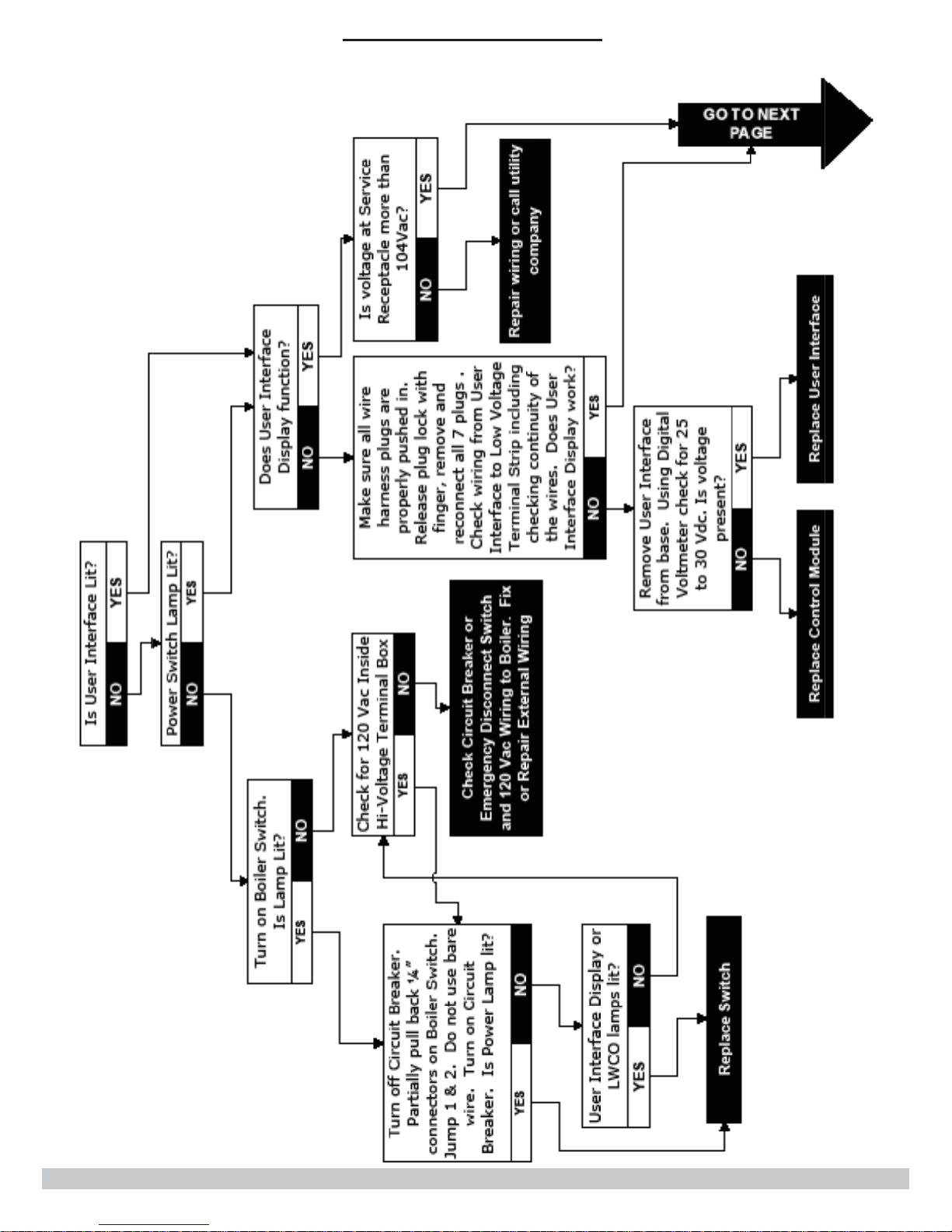
13 - TROUBLE SHOOTING
39
Page 40
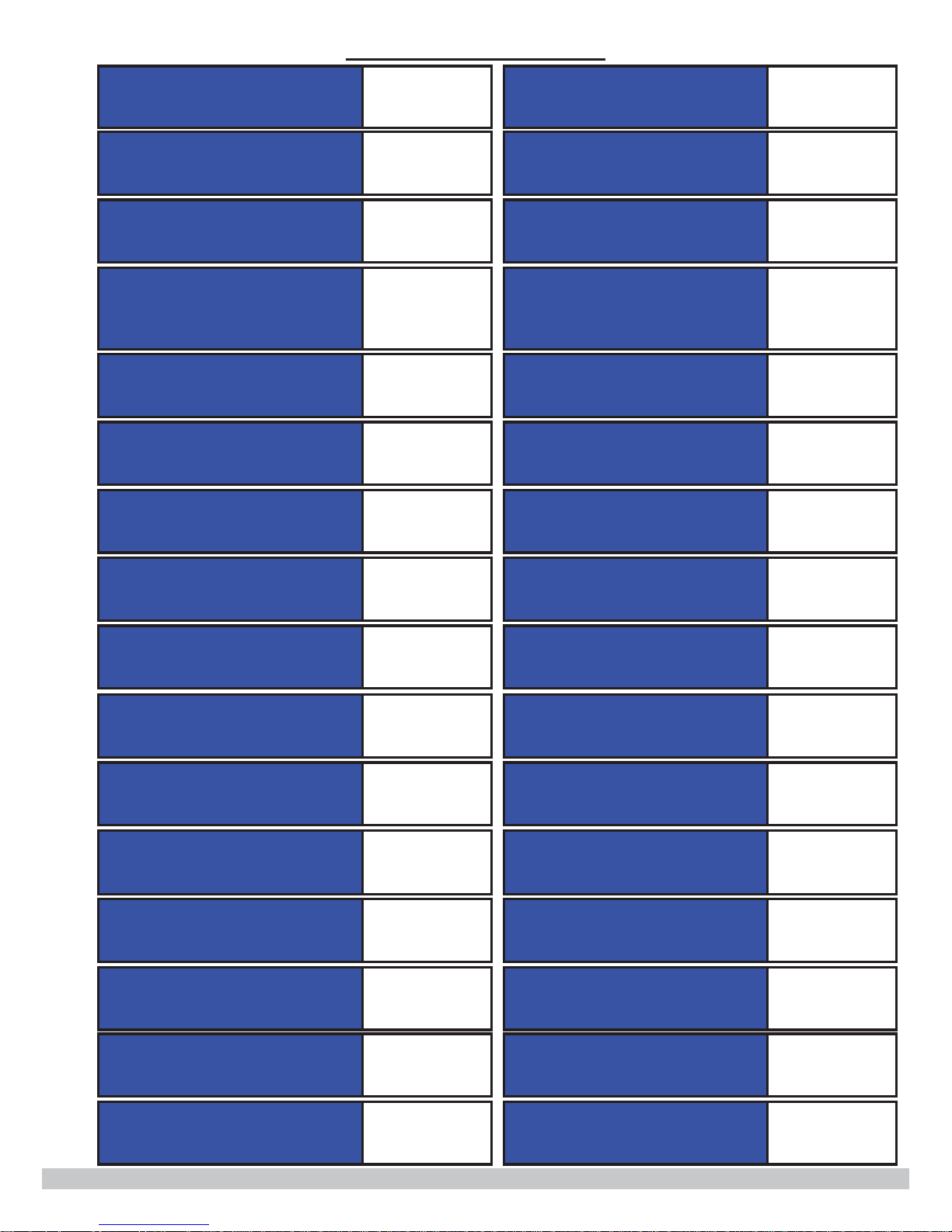
13 - TROUBLE SHOOTING
x
p
p
p
p
p
p
_ _ _ _ _ _ F P _ _ _ _
Go to Page 41
Lockout Alarm Blocking Error E 3 5
Blocking Too Long Error False Flame Detect
_ _ _ _ _ _ _ _ _ _ _ _
Lockout Alarm Blocking Error E 3 6
Ignit Error Low Water Cutoff
_ _ _ _ _ _ _ _ _ _ _ _
Lockout Alarm Blocking Error E 4 0
GV Relay Error Return Temp
A 0 0
Go to Page 42
A 0 1
A 0 5
Go to Page 41
Go to Page 48
Go to Page 49
Go to Page 50
_ _ _ _ _ _ _ _ _ _ _ _
Lockout Alarm Blocking Error E 4 3
Replace Control
Module
A 0 6
Safety Relay Error Various Text Messages
_ P _ _ _ _ _ _ _ _ _ _
Go to Page 43
Lockout Alarm Blocking Error E 4 4
A 0 8
Fan Error Phase Error
_ _ _ _ _ _ _ _ _ _ _ _
Lockout Alarm Blocking Error E 4 5
A 0 9 to A 1 4
Re
lace Control
Module
Various Text Messages Net Freq Error
_ P _ _ _ _ _ _ _ _ _ _
A 1 5
Lockout Alarm Blocking Error E 4 6
Go to Page 44
Air SW Not Open Faulty Earth Error
_ _ _ _ _ _ _ _ _ _ _ _
Lockout Alarm Blocking Error E 4 7
Replace Control
A 1 6
Module
Varioius Text Various Text Messages
_ _ _ _ _ _ _ P _ _ _ _
A 1 7
Lockout Alarm Blocking Error E 5 1
Go to Page 46
Air SW Not Closed Supply Sens Open
_ _ _ _ _ _ _ P _ _ _ _
Go to Page 47
Lockout Alarm Blocking Error E 5 2
A 1 8
Max Temp Error Return Sens Open
_ _ _ _ _ _ _ P _ _ _ _
Lockout Alarm Blocking Error E 5 7
Replace Gas
A 2 0
Valve
Flame Out Too Late Flue Sens Shorted
Re
lace Control
Module
Go to Page 50
Go to Page 51
Go to Page 52
lace Control
Re
Module
Go to Page 52
Go to Page 53
Go to Page 54
_ _ _ _ _ _ _ P _ _ _ _
Lockout Alarm Blocking Error E 5 9
Flame Error 1 Supply Sens Shorted
_ _ _ _ _ _ _ P _ _ _ _
Lockout Alarm Blocking Error E 6 0
A 2 2 A 2 3
Various Text Messages Return Sens Shorted
_ _ _ _ _ _ _ P _ _ _ _
Lockout Alarm Blocking Error E 6 5
3 Flame Failures Flue Sens Shorted
_ _ _ _ _ _ _ P _ _ _ _
Lockout Alarm Blocking Error E 6 6
A 2 7 to A 3 0
Various Text Messages Reset Button Error
_ _ _ _ _ _ _ _ _ _ _ _
Blocking Error Blocking Error
E 3 1 to E 3 4
Various Text Messages Various Fan Error Te
Replace Gas
A 2 1
Valve
Re
Module
A 2 4
Go to Page 48
Re
Module
Replace Control
Module
lace Control
lace Control
40
E73 to E79
E 81, 88, 89
Go to Page 54
Go to Page 55
Go to Page 55
Error clears in
1-2 minutes
Re
lace Control
Module
Page 41
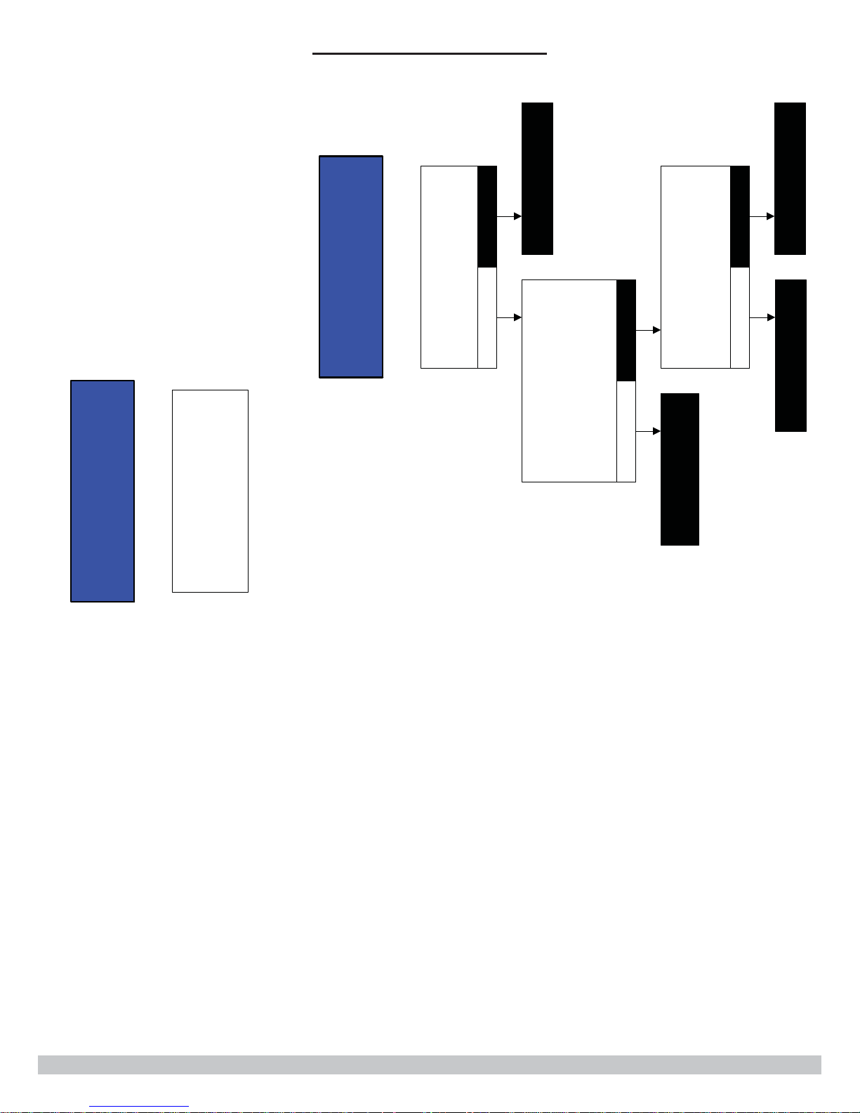
13 - TROUBLE SHOOTING
Enter Installer Menu, Boiler
Status. Scroll to most recent
Diagnose corrective action using
Lockout Alarm A 0 0
Blocking too long error
Lockout Alarm or Blocking Error.
_ _ _ _ _
appropriate Troubleshooting Tree.
to Control Module J13?
Is harness connected to Gas
Lockout Alarm A 0 5
GV relay error
Valve? Is harness connected
_ P _ _ _
NOYES
Connect harness
YES NO
and Control Module?
Valve. Does each wire have
Disconnect harness from Gas
continuity between Gas Valve
Replace harness
Replace Gas Valve
1.0 and 1.2 kohms?
Disconnect harness from
resistance across J13-3 and
Control Module J13. Measure
YES NO
J13-4. Is resistance between
Module
Replace Control
41
Page 42
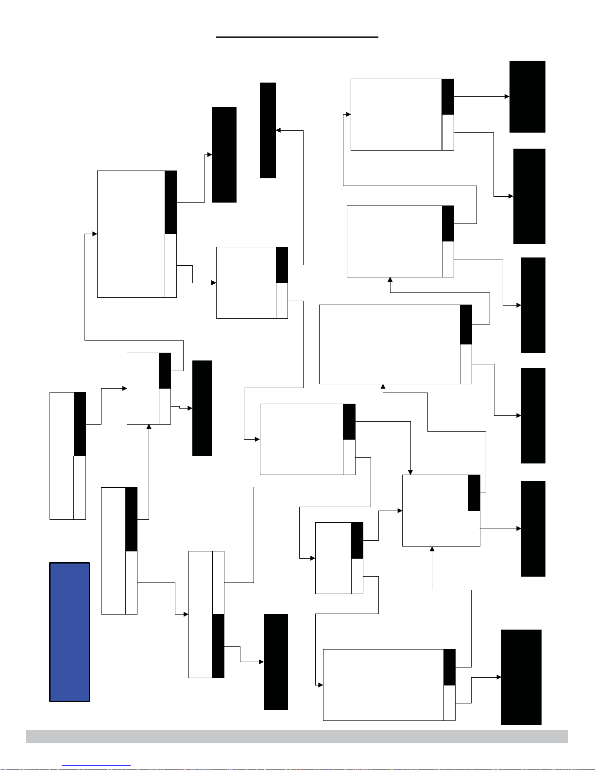
Check all wires, including
Igniter and Flame Sensor
leads. Check for proper and
connected?
board. Are all wires
tight connections to control
YES NO
13 - TROUBLE SHOOTING
Inspect the flue
way along the
sides of the baffle
near the coil for
Clear vent blockage
check for secure fit
Connect all wires and
Remove the gas
train including the
flue transition.
Remove the
burner and
blockages.
Is there any
apparent debris or
inspect.
Any sign of
obstruction of the
damage to burner
surface?
Tree
Valve
Refer to the Gas
Troubleshooting
YES NO
flue way?
section
Refer to the Heat
Exchanger cleaning
YES NO
Is this a new boiler on first
startup?
NO
YES
Is the Gas Shutoff
Valve closed?
propane gas?
YES NO
Is this boiler to run with
YES NO
valves
Open gas shutoff
YESNO
Inspect Vent
System for
blockages.
YES NO
Is the vent system
clear?
Reset the boiler by
pressing the
‘Reset’ button.
When the boiler
tries to ignite, is
there a strong,
Disconnect the gas
valve electrical
harness and close
`
consistent spark
evident throught
the sight glass?
Does the boiler
ignite and stay
running?
the gas shutoff
valve.
With the ignition
lead connected to
the igniter, hold the
YES NO
YES NO
tip near the chassis
ground and attempt
ignition.
Remove the flame
rod and igniter rod
and inspect. Is
Is a spark observed
between the igniter
and ground?
there any
indication of
damage or debris
baked on?
Replace Burner
YES NO
Replace Control
YES NO
rod or igniter
Replace/clean flame
Is the propane gas orifice
Lockout Alarm A 0 1
Ignit error
_ P _ _ _
properly installed?
Install propane
Orifice
Enter the Installer
Menu and place
the boiler into test
mode in high fire.
Once the boiler
starts, go to the
boiler status
screen and
monitor the flame
signal.
YES NO
Is the flame signal
greater than
8.0uA?
Check vent
of wind effects
termination for
proper consideration
42
Page 43
13 - TROUBLE SHOOTING
NO
operating?
YES
Is Combustion Air Blower
Lockout Alarm A 0 8
Fan error
_ _ _ _ _
NO
Are 3-wire and 4-wire
YES
harnesses connected to
Combustion Air Blower?
Connect harness
Disconnect harness from
NO
Is voltage 120 Vac ± 10%
Control Module J9. Measure
voltage between J9-2 and J9-3.
Air Blower
Replace Combustion
NO
YES
Module
Replace Control
NO
YES
Disconnect 3-wire harness
Measure continuity in each
from Combustion Air Blower.
wire. Continuity in each wire?
Replace harness
Air Blower
Replace Combustion
speed increase?
YES
Disconnect 4-wire harness
from Combustion Air Blower.
Does Combustion Air Blower
43
Replace harness
in each wire of 4-wire harness
YES NO
(yellow, red, white, black)?
Module
Replace Control
Disconnect harness from
Control Module J9. Continuity
Page 44
13 - TROUBLE SHOOTING
Correct wiring
NO
Module
Replace Control
operating?
YES NO
Is Combustion Air Blower
Lockout Alarm A 1 5
Air SW not open
_ P _ _ _
YES NO
terminals (interchangeable)?
Air Pressure Switch NO and C
Are orange wires connected to
Air Pressure Switch.
Disconnect orange wires from
NO
YES
Combustion Air Blower?
Is 4-wire harness connected to
Connect harness
NO
terminals?
YES
Continuity across NO and C
NO
Disconnect harness from
between J16-2 and J16-3?
Control Module J16. Continuity
Switch
Replace Air Pressure
Replace wire(s)
YES
Replace harness
44
YES
and Control Module J9.
Disconnect 4-wire harness
Continuity in each wire?
from Combustion Air Blower
Air Blower
Replace Combustion
Page 45

Silicone Tubing
Flue Transition
Test Port
Combustion Air
Analyzer Port
13 - TROUBLE SHOOTING
Differential Air
Pressure Switch
Vinyl Tubing
Vinyl Tubing
Tee
Vinyl Cap
(Typ. 2)
Test Lines
-
(Or Differential Pressure Gauge)
Inclined Manometer
+
!
DANGER
Replace all test port caps. Failure to comply will
result in death or serious injury.
Flue
Transition
Test Port
Combustion
Air Analysis
Test Port
45
Page 46
13 - TROUBLE SHOOTING
Connect harness
operating?
YES NO
Is Combustion Air Blower
Lockout Alarm A 1 7
Air SW not closed
_ P _ _ _
YES NO
Combustion Air Blower?
Is 3-wire harness connected to
in each wire?
YES NO
Control Module J9. Continuity
Are orange wires connected to
NC and C?
Air Pressure Switch terminals
Disconnect harness from
Disconnect 3-wire harness
from Combustion Air Blower.
NOYES
Connect wires
Replace wires
and J9-3. Is voltage
approximately 120 VAC?
Measure voltage between J9-2
Replace wires
Module
NOYES
Replace Control
Air Blower
Replace Combustion
See page 45
is each wire?
YES NO
Disconnect wires from Air
Pressure Switch. Disconnect
harness from J16. Continuity
46
Remove obstructions
YES NO
Is combustion air and vent
piping free of obstructions?
Connect manometer to Air
Pressure Switch tubing (see
INSTRUCTIONS to initiate
boiler operation. Is pressure
figure). Follow OPERATING
greater than 0.14" wc (35 Pa)?
Air Blower
NOYES
Replace Combustion
Switch
Replace Air Pressure
Page 47
13 - TROUBLE SHOOTING
Replace Control
Module
NTC Resistance Chart
°F°C Resistance
3K to 9K ohms
50 to 9010 to 32 9K to 24K ohms
90 to 130
32 to 54
2K to 1K ohms
2K to 3K ohms
150 to 200
130 to 150
54 to 66
66 to 94
and Control Module J13.
Temperature Supply Switch
Lockout Alarm A 1 8
Max Temp Error
Disconnect harness from High
_ _ _ _ _
NO
Switch 3?
YES
1? Continuity from J13-6 to
Continuity from J13-5 to Switch
Replace wire(s)
NO
YES
less than 185°F (91°C)?
Is supply water temperature
YES NO
Switch open (no continuity
Is High Temperature Supply
between terminals 1 and 3)?
Switch
Replace High
Temperature Supply
Switch
Replace High
Temperature Supply
YES NO
High Temperature Supply
Switch terminals 2 and 4?
Measure resistance across
YES NO
Switch open (no continuity
Is High Temperature Supply
between terminals 1 and 3)?
Replace High
Does resistance match supply
water temperature (see table)?
Switch
Temperature Supply
Module
Replace Control
47
Page 48
13 - TROUBLE SHOOTING
clean and secure?
Inspect harness connection
Lockout Alarm A 2 4
3 flame failures
Flame Sensor. Is connection
_ P _ _ _
NO
YES
Replace Flame
Sensor or harness
NO
YES
free of contamination?
Remove Flame Sensor. Is rod
Clean or replace
Follow OPERATING
Flame Sensor
INSTRUCTIONS to initiate
Menu, Boiler Status, Flame
boiler operation. Enter Installer
NO
than 3.7 uA?
YES
Signal. Is flame signal greater
Replace Flame
Sensor and Burner
Module
Replace Control
Blocking Error E 3 5
False flame detect
Inspect burner through sight
_ P _ _ _
Module
NOYES
glass. Is flame present?
Replace Control
Turn Gas Shutoff
Valve clockwise to
closed position.
Follow instructions
TO APPLIANCE.
TO TURN OFF GAS
Replace Gas Valve.
48
Page 49
13 - TROUBLE SHOOTING
NO
amber lamp lit?
NO
YES
Check Low Water Cutoff.
NO
YES
Is Green Power Lamp lit?
NO
YES
Is Harness plugged into Low Water Cutoff?
Is Black/White Harness plugged into 24 volt harness?
Is Blue/Yellow Harness plugged into 24 Vac Transformer?
Insert Harness
Disconnect Black/White
NO
Disconnect Blue/Yellow
harness from Transformer.
YES
Vac. Is 24 to 30 Vac present?
Using digital meter check for 24
Connect harness to
Transformer. Disconnect
Harness?
YES
Is 120 Vac measured at
Harness from Transformer.
NO
terminals 1 & 2?
YES
Cutoff. Is 24 Vac at
harness from Low Water
Replace Main Harness
Replace Transformer
Blocking Error E 3 6
Low Water Cutoff
_ _ _ _ _
Check Low Water Cutoff. Is
NO
Replace Low Water Cutoff Replace Harness
Insert Harness
Replace Harness
YES
system and refill.
Repair System Piping,
remove any remaining air in
Control Module J16?
Is harness plugged into
Harness OK?
YES NO
continuity if harness.
Low Water Cutoff and
Disconnect harness from
Control Module J16. Check
Replace Low Water Cutoff
49
Page 50
13 - TROUBLE SHOOTING
Blocking Error E 4 4
_ P _ _ _
Phase error
Measure incoming power with
NOYES
VAC? Is 120 VAC (N)
volt meter. Is terminal 120
approximately 0 VAC?
VAC (L) approximately 120
Module
Replace Control
Correct field wiring
Blocking Error E 4 0
Return Temp
_ _ _ _ _
Is correct harness connected to
return sensor (2 Brown Wires)?
NOYES
Correct wiring
oriented properly?
Is Heat Exchanger Pump
YES NO
(Pump Arrow pointing down?)
Install Heat
proper orientation
Exchanger Pump in
Return Water Sensor.
Disconnect harness from
Measure resistance using
digital ohm meter. Is
resistance between 950 to
Sensor
Replace Return Water
33,000 ohms?
YES NO
Module
Replace Control
50
Page 51
13 - TROUBLE SHOOTING
+/- 2%
Blocking Error E 4 5
Net frequency error
_ P _ _ _
and 61 Hz?
Is power supply between 59
NO
YES
stabilized power
Provide frequency
supply rated at 60 Hz
breaker
NO
loose or faulty?
YES
Is power supply circuit breaker
Replace circuit
NO
YES
Is field wiring loose or faulty?
Module
Replace Control
Correct wiring
51
Page 52
13 - TROUBLE SHOOTING
Insert Harness
NOYES
Replace Wires
Sensor
Blocking Error E 4 6
Faulty ground
_ P _ _ _
Control Module J5?
Supply Water Sensor?
Is harness plugged into
Is harness plugged into
Blocking Error E 5 1
Supply Sens Open
_ P _ _ _
conductor
Connect ground
YES NO
connected to High Voltage
Is field grounding conductor
Terminal Strip 120 VAC (G)?
Replace Supply Water
Continuity?
YES NO
Control and Sensor.
brown wires between
Disconnect J5 from Control
Module. Using digital meter
measure check continuity of
11 andJ5-3. Measure
digital meter. Estimate
resistance between Supply
Using digital meter measure
RTD Resistance Chart
conductor
NOYES
Correct faulty ground
resistance of Sensor with
Water Sensor terminals J5-
3K to 9K ohms
°F°C Resistance
50 to 9010 to 32 9K to 24K ohms
90 to 130
32 to 54
Sensor temperature. Does
2K to 3K ohms
130 to 150
54 to 66
it fall in the range of the
RTD Resistance Chart?
2K to 1K ohms
150 to 200
66 to 94
YES NO
Replace Control Module
10 ohms?
Disconnect field wiring. Is
neutral and ground less than
continuity between field wiring
Module
Replace Control
52
Page 53
13 - TROUBLE SHOOTING
Insert Harness
Replace Wires
NOYES
Blocking Error E 5 2
Return Sens Open
_ P _ _ _
Return Water Sensor?
Is harness plugged into
Is harness plugged into
Control Module J5?
Check continuity of brown
wires between Return Water
YES NO
Sensor and Control Module
J5-4 and J5-12 Continuity?
Using digital meter measure
RTD Resistance Chart
Water Sensor terminals.
resistance between Return
°F°C Resistance
Estimate Sensor
Measure resistance of
Sensor with digital meter.
temperature. Does it fall in
2K to 3K ohms
3K to 9K ohms
50 to 9010 to 32 9K to 24K ohms
90 to 130
130 to 150
YES NO
Resistance Chart?
the range of the RTD
2K to 1K ohms
150 to 200
Sensor
Replace Return Water
Replace Control Module
53
54 to 66
32 to 54
66 to 94
Page 54
13 - TROUBLE SHOOTING
Replace wires
Switch 4?
Supply Water Sensor.
Blocking Error E 5 9
Supply Sensor Shorted
Disconnect wire harness from
_ P _ _ _
NOYES
Switch terminals 2 and 4.
High Temperature Supply
Measure resistance across
Does resistance match supply
water temperature (see table)?
Insert harness
Disconnect J5 from Control
Module. Continuity between
Replace High
Temperature Supply
J5-11 and Switch 2?
Continuity between J5-3 and
Switch
YES NO
Module
Replace Control
NTC Resistance Chart
°F°C Resistance
3K to 9K ohms
50 to 9010 to 32 9K to 24K ohms
90 to 130
32 to 54
2K to 1K ohms
2K to 3K ohms
150 to 200
130 to 150
54 to 66
66 to 94
NOYES
Module J5?
Temperature Sensor? Is
Is harness plugged into Vent
Blocking Error E 5 7
Flue sens open
harness plugged into Control
_ P _ _ _
Replace wires
for each blue wire?
Temperature Sensor and
Disconnect harness from Vent
YES NO
Control Module J5. Continuity
Vent Temperature Sensor
Measure resistance across
54
match estimated flue
terminals. Does resistance
temperature (see table)?
YES NO
Replace Vent
Temperature Sensor
Module
Replace Control
Page 55
13 - TROUBLE SHOOTING
Blocking Error E 6 5
Flue Sens Shorted
_ P _ _ _
NOYES
Does resistance match
Flue Temperature Sensor.
Measure Sensor resistance.
Disconnect wire harness from
estimated flue temperature?
Replace Flue
Temperature Sensor
in blue wires?
Disconnect harness from
Control Module J5. Continuity
YES NO
°F°C Resistance
Replace wires
Module
Replace Control
NTC Resistance Chart
50 to 9010 to 32 9K to 24K ohms
2K to 3K ohms
3K to 9K ohms
90 to 130
130 to 150
54 to 66
32 to 54
2K to 1K ohms
150 to 200
66 to 94
Disconnect harness from
Blocking Error E 6 0
Return sens shorted
_ P _ _ _
Disconnect harness from
Control Module J5. Measure
less than 50 ohms?
Return Water Sensor.
Measure resistance across
YES NO
sensor terminals. Is resistance
Sensor
Replace Return Water
55
resistance between brown
wires at terminals J5-4 and J5-
12. Is resistance less than 50
NOYES
ohms?
Module
Replace Control
Replace wires
Page 56

14.1 Connection Diagram
15 - WIRING DIAGRAM
56
Page 57
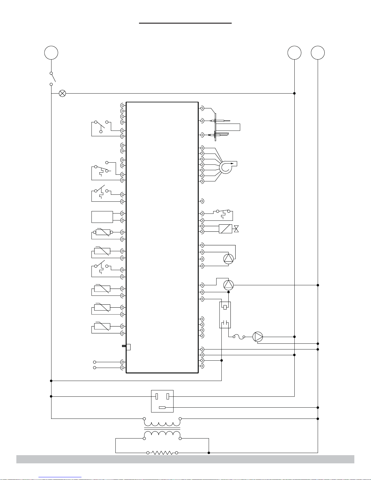
15 - WIRING DIAGRAM
14.2 Schematic Diagram of Ladder Form
L
LIGHTED
POWER
SWITCH
LWCO
AIR
PRESSURE
SWITCH
CH
THERMOSTAT
USER
INTERFACE
SUPPLY
SENSOR
RETURN
SENSOR
DHW
THERMOSTAT
FLUE
SENSOR
SYSTEM
SENSOR
(OPTIONAL)
OUTDOOR
SENSOR
ARGUS LINK
POWER
ARGUS LINK /
MULTI BOILER
(OPTIONAL)
43
2 NO
C
3 NC
DISPLAY
4
2
ON
OFF
J22-6
J22-5
J22-4
J22-3
J16-1
J16-4
J16-5
J16-8
J16-6
J16-7
J16-3
J16-2
J5-9
J5-1
J5-10
J5-2
J5-11
J5-3
J5-12
J5-4
J5-13
J5-5
J5-14
J5-6
J5-15
J5-7
J5-16
J5-8
S4
J18-1
J18-2
ARGUS
CONTROL
J12
J13-2
J9-1
J9-2
J9-6
J9-7
J9-5
J9-4
J9-3
J13-1
J13-5
J13-6
J13-3
J13-4
J7-1
J7-4
J7-3
J7-2
J6-1
J6-3
J6-2
J4-1
J4-2
J4-3
J4-4
J2-1
J2-2
J2-3
J2-4
NG
G
BURNER
T2
PE
DC+/L
+
DATA/PWM
HALL
GND
DC-/N
1
G
L
N
L
N
L
5
G
N
L
GROUND
FLAME SENSOR
IGNITION
FAN
120VAC
3
LIMIT
GAS VALVE
HEAT EXCHANGER
PUMP 120 VAC
DHW PUMP
120 VAC
FIELD SUPPLIED
1
CH PUMP
RELAY
120 VAC
43
5 A
BREAKER
CH PUMP
120 VAC
FIELD SUPPLIED
LM N
G
LWCO
24 VAC
1
RECEPTACLE
(REAR SHOWN)
120V / 24V, 15VA
TRANSFORMER
2
57
Page 58
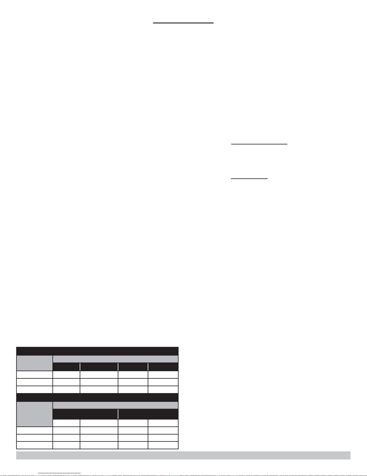
16 - GLOSSARY
ANSI• - American National Standards Institute, Inc. oversees creation and maintenance of voluntary consensus standards, including ANSI Z21.13/CSA 4.9: Gas-Fired
Low Pressure Steam and Hot Water Boilers.
ASTM • - American Society for Testing and Materials. ASTM
International is one of largest voluntary standards development organizations in world trusted source for technical
standards for materials, products, systems, and services.
Known for their high technical quality and market relevancy, ASTM International standards have important role in
information infrastructure that guides design, manufacturing and trade in the global economy.
AUTHORITY HAVING JURISDICTION -• Individual or organization adopting and enforcing codes, rules, and by-laws
HIGH-VOLTAGE• - Circuit involving potential of not more
than 600 volts and having circuit characteristics in excess
of those of low-voltage circuit.
IGNITER• - Device utilizing electrical energy to ignite gas
at main burner.
LEAK CHECK• - Operation performed on gas piping system
to verify system does not leak.
LOW WATER CUTOFF• - Device constructed to automati-
cally cut off fuel supply when surface of water in boiler
falls to lowest safe water level.
LOW-VOLTAGE• - Circuit involving potential of not more
than 30 volts.
METRIC GAS METERS•
governing various concerns of community. Commonly
referred to as "fi nal authority" for any matters relating
to LIFE SAFETY and BUILDING CONSTRUCTION within a
community.
Btu• - Abbreviation for British Thermal Unit. Quantity of
For example: Gas Meter measures 0.1 cubic Meters in 100
seconds
heat required to raise temperature of 1 pound of water1°F.
BURNER • - Device for fi nal conveyance of gas or mixture of
gas and air, to combustion zone.
COMBUSTION • - Rapid oxidation of fuel gases accompanied
by production of heat or heat and light. Complete combustion
of fuel is possible only in presence of adequate supply of
Oxygen.
COMBUSTIBLE MATERIAL• - Materials made of or surfaced
with wood, compressed paper, plant fi bers, or other
materials capable of being ignited and burned. Such material shall be considered combustible even though fl ame-
proofed, fi re-retardant treated, or plastered.
PRESSURE TEST• - Operation performed to verify gas
tight integrity of gas piping following its installation or
modifi cation.
PURGE • - To free gas conduit of air or gas, or mixture of
gas and air.
PURGE TIME• - Period of time intended to allow for dis-
sipation of any unburned gas or residual products of
combustion.
QUALIFIED AGENCY• - Any individual, fi rm, corporation, or
company engaged in and responsible for:
CONDENSATE• - Liquid separated from fl ue gas due to re-
duction in temperature.
DIRECT VENT BOILER• - Boiler constructed and installed so
all combustion air is derived directly from outdoors and all
vent gases are discharged to outdoors.
DRAFT• - Pressure difference causes gases or air to fl ow
through a chimney, vent , fl ue or appliance.
FLUE GASES • - Products of combustion plus excess air in
appliance fl ues or heat exchanger.
GAS PIPE SIZES•
NATURAL GAS
Length of Pipe
- Ft.
20 92,000 190,000 350,000 625,000
40
60 50,000 105,000 195,000 365,000
Length of Pipe
- Ft.
20
40 90,000 145,000 129,000 267,000
60 72,000 121,000 103,000 217,000
Pipe Capacity - BTU Per Hour Input Includes Fittings
1/2” 3/4” 1” 1 1/4”
63,000 130,000 245,000 445,000
PROPANE GAS
Pipe Capacity - BTU Per Hour Input Includes Fittings
Copper Tubing
(Outside Diameter)
5/8” 3/4” 1/2” 3/4”
131,000 216,000 189,000 393,000
Iron Pipe
SAFETY RELIEF VALVE• - Valve designed to relieve
pressure, in hot water supply system, when pressure
exceeds pressure capability of equipment.
SAFETY SHUTOFF DEVICE• - Device that will shut off gas
supply to controlled burner in event source of ignition
fails.
SEDIMENT TRAP• - Gas piping arrangement designed to
collect any liquid or solid contaminant before reaching
gas valve.
VENT• - Passageway used to convey fl ue gases from
appliance vent connector to outdoors.
VENTING SYSTEM• - Continuous open passageway from
of appliance vent connector to outdoors for purpose of
removing fl ue or vent gases.
127,116 x cu meters
MBH
MBH
=
Seconds
127,116 x 0.1
=
100
= 127 MBH
Installation, testing, or replacement of gas piping, •
or connection, installation, testing, repair or
servicing of appliances and equipment.
Experienced in such work.•
Familiar with all precautions required.•
Complies with all requirement of authority having •
jurisdictions.
58
Page 59
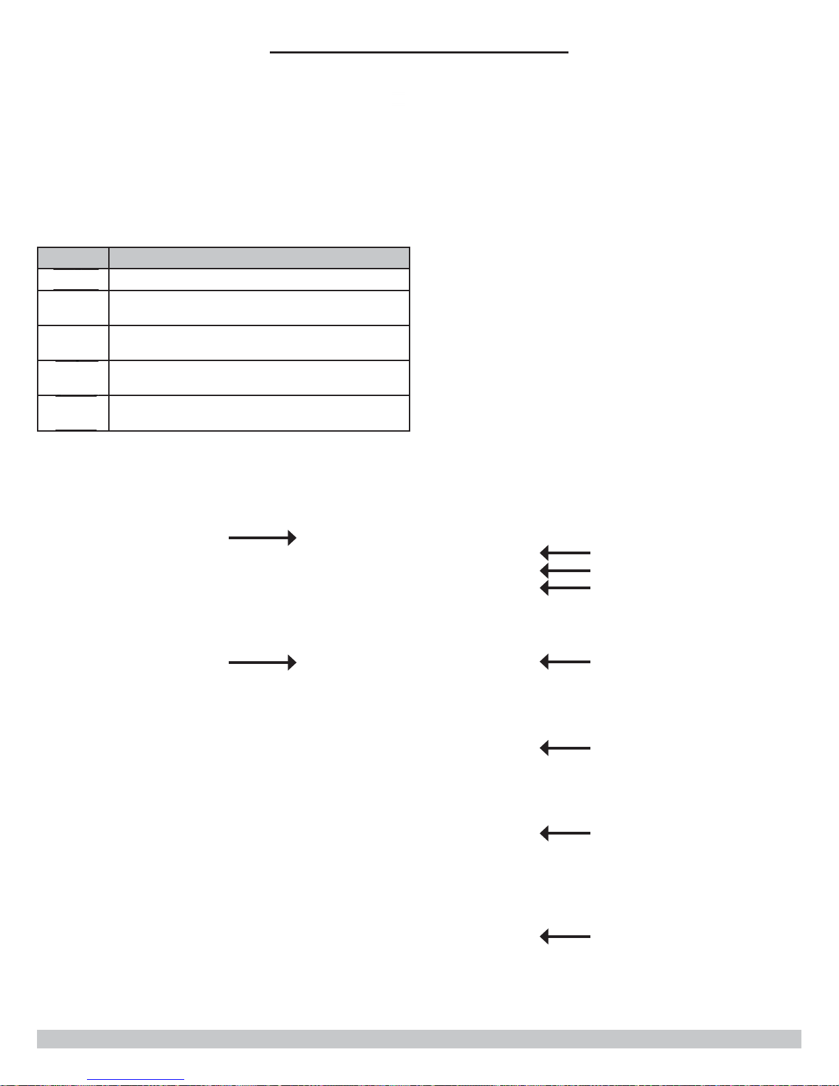
APPENDIX A - CONTROL MODULE
l
e
1.1 Introduction
The boiler is equipped with a programmable electronic con-
trol and user interface module.
n-
1.2 Operation
Display: 4x20 character LCD screen to show boiler •
status.
Function Keys•
Key Description
- Manual Lockout Reset
- Enter/Exit user menu
- Go to previous screen
- Select a menu item
- Confi rm new parameter value
- Scroll up to next menu item
- Increase value
- Scroll down to next menu item
- Decrease value
Operation with LCD character display module
eration with LCD character display modu
1.3 Status Indication
The following status screens can be displayed:
Boiler Status Indicator
F = Flame Detected
SERVICE Reminder
P = Boiler Pump On
B = Combustion Air Blower On
S = Safety Relay Check
G = Gas Valve Open
D = DHW Pump On
Combustion Air Blower
Speed Indicator
Service Reminder Indica
Boiler in Standby Mode
Boiler Supply Water
Temperature Indicator.
tor
Boiler Running in Central
Heat mode
Boiler Running in DHW
mode
Lockout Alarm Indicator
Error code and short text description is displayed
Press 'Reset" key for manual
reset.
Boiler Running in DHW
mode
Error code and short text
description is displayed Boiler
automatically returns to Standby Mode when condition is
eliminated.
59
Page 60
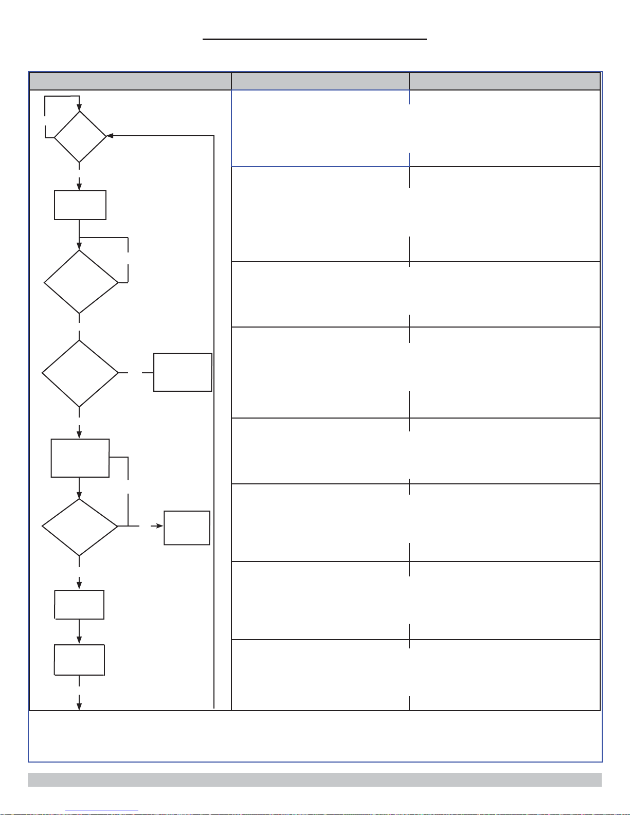
1.4 Sequence of Operation
Operational State User Interface Display Explanation
APPENDIX A - CONTROL MODULE
No
Heat
Demand?
Yes
DHW CH
Pump on
Supply
Temperature
<Setpoint?
Yes
Air Pressure
Switch Open?
No
No
Lockout
Error
A15
Standby: No Demand
Boiler operates in standby mode until
demand for Central Heat (CH) or Domestic Hot Water (DHW) is detected.
CH or DHW pump is turned based on
type of heating demand.
(CH call is illustrated)
Control Module compares supply
temperature to set point. Boiler proceeds
to ignition if supply temperature is less
than set point.
Air Pressure Switch is checked for open
circuit before energizing Combustion Air
Blower
Closed Air Pressure Switch during this
stage will result in Lockout Error.
Yes
Combustion
Air Blower
On
Air Pressure
Switch
Closed?
Yes
15 Second
Prepurge
Ignition
Sparking
After 2 seconds
No
After
3
Trials
Lockout
Error
A17
Combustion Air Blower is energized to
prove fl ow though Combustion and Vent
Systems.
Air Pressure Switch is checked for closed
circuit.
Open Air Pressure Switch during this
stage will result in Lockout Error after 3
trials.
Combustion Air Blower speed
modulates to prepurge setting for 15
seconds.
Initiates sparking
60
Page 61
1.4 Sequence of Operation
Operational State User Interface Display Explanation
After 2 seconds
Flame
Detected?
No
Gas Valve
Energized
Yes
Lockout
Error A21
5 Ignition
Lockout A01
APPENDIX A - CONTROL MODULE
If fl ame detected before Gas Valve opens
during ignition boiler will lockout.
Please refer to troubleshooting guide.
Note:
trials,
then
Gas Valve energized to deliver air/fuel to
burner.
After 3 seconds
Flame
Detected?
Yes
Heat Demand
Met?
No
No
Simultaneous
DHW + CH
Demand?
Yes
DHW
Priority
Mode
No
See Max DHW
Priority Time
30 second
post purge
Yes
Setting
Flame undetected 3 seconds boiler will
de-energize Gas Valve and enter post
purge mode for 30 seconds.
Ignition attempted 5 times before lockout.
Flame detected Boiler will run provided
all operational and safety devices devices
within limits
Refer to section 1.5 for more information.
Control module adjusts fi ring rate ac-
cording to heating demand. When Boiler
detects demand met, will enter post
purge mode and enter standby mode.
If simultaneous demand for Central Heat
and DHW, boiler will enter DHW Priority
Mode.
Mode limits amount of time boiler can
run in DHW mode to meet CH demand.
Max DHW Priority Time setting determines maximum time allowed for DHW
heating mode.
Please refer to section 1.5 for more
information.
61
Page 62
1.5 Theory of Operation
Standby: No Deman d
75° F
MENU
Bo i l e r St a t us
Set t i ngs
Cascade Sta tus
BO I LER STATUS ▲
Suppl y 140 °F
Return 120 °F
DHW S t a t Open
▼
BO I LER STATUS ▲
Syst em N.C.
Flue 132°F
Outdoor 36 °F
▼
BO I LER STATUS ▲
Bo i l e r Pump Of f
CH / Sys t em Pump O f f
DHW Pump O f f
BO I LER STATUS
Cur rent Suppl y
Setpoint 160°F
▼
APPENDIX A - CONTROL MODULE
STANDBY
User Menu
User Menu
User Interface Display
Explanation
Boiler operates in standby mode until demand for Central Heat
(CH) or Domestic Hot Water (DHW) is detected.
User Menu can be accessed by pressing ‘Menu’ key on user
interface.
Installer Menu can be accessed by simultaneously holding
‘Menu’ and ‘Enter’ keys for 5 seconds.
User Menu structure includes:
‘Boiler Status’ submenu– User can monitor general boiler •
status parameters such as sensor temperatures and
pump operation.
‘Settings’ submenu – User can view CH , adjust DHW •
supply water set points and also select control language.
‘Cascade Status’ submenu – Boiler set to function as •
part of multiple boiler installation; submenu used to view
runtime parameters. See Multiple Boiler Manual.
Boiler Status
Supply Temperature set point displayed.
If boiler running in CH mode, CH set point displayed.
Note:
While running in Outdoor Reset mode, this value may •
change in proportion with the outdoor temperature.
If the boiler is running in DHW mode, the DHW supply set •
point is displayed.
Several boiler runtime parameters can be viewed while in ‘Boiler
Status’ submenu.
Operational status of pump system also shown.
Information available during all states of boiler operation.
Sensor values with troubleshooting tree used to diagnose
typical problems.
62
Page 63
SETT I NGS
Cen t ra l Hea t i ng
Setpoint
°F
▼
SETT I NGS ▲
DHW Se t po i n t
°F
▼
SETT I NGS ▲
Change
Temperature Uni ts
Fahrenhei t °F
▼
SETT I NGS ▲
Change
Language
Eng l i sh
▼
APPENDIX A - CONTROL MODULE
Settings
User Interface Display
Explanation
Adjust CH set point to hydronic system design while in
Operating in CH Mode = 0 (CH with Thermostat) or 3 (Permanent Demand).
Closed loop software control algorithm used to meet set point
temperature boiler uses. Algorithm calculates boiler modulation
rate based on several factors.
In CH Mode = 1 (CH with Thermostat and Outdoor Reset) or 2
(CH with Full Outdoor Reset). Display will change to ‘OD Reset
Setpoint’ and cannot be changed. Controller is calculating set
point based on outdoor temperature.
Setting Range: 104..195 °F (40..91 °C)
Default Value: 140 °F (60 °C)
Note:
Explanation of available CH heating modes, refer to ‘CH •
Mode’ section located in ‘CH Settings’ submenu.
DHW set point determines supply water temperature set point
while operating in DHW mode.
Setting Range: 104..195 °F (40..91 °C)
Default Value: 180 °F (82 °C)
User interface temperature unit of measure is selected using
‘Change Temperature Units’ screen.
Fahrenheit and Celsius available.
Select user interface language using ‘Change Language’ screen.
English and French are available.
63
Page 64
INSTALLER MENU
Bo i l e r St a t us
Bo i l e r Con f i g
CH Se t t i ngs
DHW Se t t i ngs
Cascade Set t ings
System Test
STAT US
Fa n Sp e ed
Ac t ua l 4000RPM
Low Power 1560RPM
▼
STAT US ▲
Fa n Sp e ed
I gn i t i on 3500RPM
H i Power 5725RPM
▼
STAT US ▲
Fl ame
Signal 07.2uA
Fai lures 2
▼
APPENDIX A - CONTROL MODULE
User Interface Display
Installer Menu
Installer Menu
Explanation
The Installer Menu structure includes:
‘Boiler Status’ submenu – User monitors detailed boiler •
status parameters such as fl ame signal, fan speeds and
stored error codes.
‘Boiler Confi g’ submenu – Modifi es general boiler •
settings.
‘CH Settings’ submenu – Modifi es advanced Central Heat-•
ing settings including outdoor reset curve parameters
and boost function.
‘DHW Settings’ – Modifi es Domestic hot Water control •
settings such as DHW priority time.
‘Cascade Settings’ - Refer to Multiple Boiler Manual.•
‘System Test’ – Tool aids setup of boiler installation or •
diagnosis of common problems.
Boiler Status
Pulse Width Modulated Combustion Air Blower provides airfl ow
through Combustion and Vent systems.
Fan speed is digital control and is determined by control
algorithm.
Fan speed status screen indicates actual fan speed in RPM, high,
low and ignition power speed settings.
Settings are for information only to aid in troubleshooting.
Boiler equipped with ionization rod to detect presence of
combustion using fl ame rectifi cation method. When fl ame is
present, fl ame ionization rod measures small DC offset current
across fl ame to ground (i.e. burner surface).
‘Flame’ screen in ‘Boiler Status’ submenu displays information
regarding fl ame ionization system; for information only and
used in diagnosing combustion problems. See troubleshooting
guide.
64
Page 65
APPENDIX A - CONTROL MODULE
STAT US ▲
Ign i t i on Attempts
Suc c e s ful 4267
Fai led 21
▼
User Interface Display
Installer Menu
Explanation
Control module logs successful and failed ignition attempts.
Information accessed in ‘Ignition Attempts’ Screen as shown.
Ignition attempts are stored in non-volatile memory and are
retained in event of power failure.
Typical Ignition Cycle:
Following control features are implemented to ensure safe and
reliable operation of Combustion System:
Boiler Status
False Flame
Detection
Re-ignition
Intermittent
Operation
Flame out too
late
Safety relay test
UL3563 High
Limit Temperature Device
If fl ame is detected at end of pre-spark
period (Ignit_0) than lockout will occur.
If at end of safety period no fl ame detected
control will go to post-purge removing
unburned gas. Re-ignition attempt started
following same cycle. Number of re-ignition
attempts limited to 4 after which lockout
occurs.
Boiler can be fi ring continuously for 24
hours. Burner switched off and restart
sequence follows.
If fl ame detected after post purge lockout
follows.
In Safety ON/OFF state correct operation
of safety relay is proved before ignition.
Boiler comes equipped with UL353
approved temperature high limit device.
Gas Valve energized when supply
temperature exceeds 195 °F lockout follows.
65
Page 66
STAT US ▲
Bo i l e r Run T ime
CH 320HR
DHW 145HR
▼
STAT US #E39 ▲
2H r s t o prev. Block
Low Water Cutoff
▼
STAT US #A01 ▲
13H r s t o prev. Lock
Ignition Error
BO I L E R C ONF I G
Add r e s s Se l e c t i on :
Bo i l e r Address: 0▼
BO I L E R C ONF I G ▲
LOW WA T ER CUTOFF
Disabled
▼
APPENDIX A - CONTROL MODULE
User Interface Display
Boiler Status
Explanation
Boiler stores information regarding total CH and DHW run time
in hours.
Data stored in non-volatile memory and retained in event of
power failure.
Boiler logs last 16 blocking errors and 16 locking errors in
non-volatile memory. Information retained in event of power
failure.
Most recent blocking error code and its text description
displayed with elapsed time in hours since logged.
Optional Computer interface Kit purchased separately to view
extended error code history
‘Address Selection” screen used to set boiler position in multiple
boiler cascade installation. Refer to Multiple Boiler Installation
Manual.
Default setting of ‘0’ indicates boiler is operating in single boiler
mode.
Boiler Confi guration
Boiler incorporates integrated Low Water Cutoff device (LWCO)
disables boiler when low water condition exists. LWCO device
located at high point of internal Heat Exchanger loop to detect
low water condition.
Detection of low water condition will result in blocking error,
boiler will automatically resume normal operation when proper
water level returns. Refer to Troubleshooting Guide.
LWCO device can be disabled for diagnostic purposes or where
applicable code permits.
66
Page 67
BO I L E R C ONF I G ▲
Pump Mo de MODE: 0
CH o r C H&DHW
▼
BO I L E R C ONF I G ▲
SERV I C E REMI NDER
Status On
Rem i nder 365 days
APPENDIX A - CONTROL MODULE
User Interface Display
Explanation
Two pump modes are available:
Pump Mode = 0 ‘CH or CH&DHW’
1.
Mode either CH or DHW pump terminal energized •
dependant on demand (CH or DHW).
CH and DHW pumps not energized at same time.•
Simultaneous call for CH and DHW, energized pump •
dependant on boiler currently supplying CH or DHW
demand. Refer to DHW Priority settings below.
Typical hydronic system design with separate CH and DHW •
Pumps.
Pump Mode = 4 ‘System Pump’
2.
One external system pump installed in the hydronic system •
In mode only . Pump will energize independent of type of
demand (CH or DHW).
Connect pump to CH/System Pump electrical terminal •
block. See page ZZ for diagram
Boiler Confi guration
DHW pump terminal does not function.•
Typical hydronic system design utilizes zone valves for all •
CH zones and DHW indirect tank.
Note:
TPump Mode selection depends on electrical and hy-•
dronic system design. Refer to Installation, Maintenance
Manual for recommended hydronic piping and electrical
confi gurations.
Internal boiler pump energized anytime demand exists •
regardless of Pump Mode setting or type of demand (CH
or DHW).
‘Service Reminder’ allows installer to enable or disable service
reminder notifi cation on User Interface at predefi ned interval
Service reminder does not affect boiler operation i. It is
reminder to t End User that routine preventative maintenance
required by qualifi ed service technician.
Allowed Range: 1..999 days
67
Page 68
CH SETT INGS
CH mod e MODE:1
CH w i t h thermostat
▼
APPENDIX A - CONTROL MODULE
User Interface Display
CH Settings
Explanation
4. Central Heating (CH) modes available:
CH Mode = 0 ‘CH with Thermostat’•
Boiler will attempt to satisfy CH demand while CH ther-•
mostat input is closed.
Boiler will modulate its fi ring rate to maintain CH set •
point and match system heat load.
CH set point adjusted in ‘Settings’ submenu under ‘User •
Menu’
CH Mode = 1 ‘CH with Thermostat and Outdoor Reset’•
Boiler will attempt to satisfy CH demand when CH ther-•
mostat input is closed.
Boiler will modulate its fi ring rate to maintain CH set •
point and match system heat load.
CH set point calculated as function of outdoor tem-•
perature using outdoor reset curve. See fi gure x.x
• CH Mode = 2 ‘CH with Full Outdoor Reset’
Boiler will permanently attempt to satisfy CH de-•
mand.
CH thermostat input is ignored.•
CH set point calculated as function of outdoor •
temperature using outdoor reset curve. See fi gure. x.x
CH Mode = 3 ‘CH with Permanent Demand’•
Boiler will permanently attempt to satisfy CH •
demand.
CH thermostat input is ignored.•
CH set point is adjusted in ‘Settings’ submenu under •
‘User Menu’
Note:
• Once CH demand is satisfi ed (i.e. CH thermostat opens or
boiler determines its minimum fi ring rate exceeds system
heating load):
Burner shuts off, boiler enters post purge.•
CH pump continues to run for 30 seconds.•
Control will wait until Anti-cycle time of 180 seconds •
elapses before boiler fi res again. Prevents short-
cycling.
• The internal boiler pump is energized anytime a demand
exists regardless of Pump Mode setting or type of demand (CH or
DHW).
68
Page 69
CH SETT INGS ▲
Warm Weather
Shutdown Temp
70°F
▼
CH SETT INGS ▲
Reset Curve Design
Bo i l e r 180°F
Ou t do o r 25°F
▼
CH SETT INGS ▲
R.Curve Mild Weath.
Bo i l e r 70°F
Ou t do o r 70°F
▼
CH SETT INGS ▲
Reset Curve
Bo i l e r Min 070°F
Bo i l e r Max 180°F
▼
APPENDIX A - CONTROL MODULE
User Interface Display
Allowed Range: 35..100 °F (2..38 °C)
Default Setting: 70 °F (21 °C)
A
Allowed Boiler Range: 60..195 °F
(40..91 °C)
Default Boiler Setting: 180 °F ( 82
°C)
B
Explanation
Outdoor temperature greater than Warm Weather Shutdown
Temperature, demand for CH blocked and pumps stopped.
Boiler capable of operating in Outdoor Reset Mode when
included Outdoor Sensor connected and proper CH Mode
selected.
If CH Mode = 1, ‘Outdoor Temperature Reset with Thermostat’ or 2, ‘Full Outdoor Reset’ boiler will adjust CH set point
proportional to outdoor temperature as defi ned by Outdoor
Reset Curve below.
Outdoor reset curve adjusted by modifying Design and Mild
Weather reference temperatures. See points A & of Reset Curve
below.
Calculated CH set point always limited between ‘Reset Curve
Boiler Minimum/Maximum’ temperatures. See points C & of
Reset Curve below.
Outdoor Reset Curve
Allowed Boiler Range: 35..120 °F (2..49 °C)
Default Boiler Setting: 70 °F (21 °C)
Allowed Outdoor Range: 35..85 °F (2..29 °C)
Default Outdoor Setting: 70 °F (21 °C)
CH Settings
C
D
Allowed Min. Range: 40..180 °F (4..82 °C)
Default Min. Setting: 70 °F (21 °C)
Allowed Max. Range: 80..195 °F (27..91 °C)
Default Max. Setting: 180 °F (82 °C)
A
D
B
C
Note:
Modes only function when outdoor temperature sensor •
connected.
‘Open’ outdoor sensor detected CH set point equal to •
‘Boiler Reset Curve Design’ temperature.
Outdoor temperature used for CH set point calcula-•
tion measured once a minute and averaged with
previous measurement to address rapid outdoor
temperature variations.
69
Page 70
CH SETT INGS ▲
Boos t Function
Temp 10°F
Time 20min
▼
CH SETT INGS ▲
Max imum Power CH
Max 100%
▼
DHW S E T T I NGS
DHW m o d e MODE : 1
DHW s t o r e w i t h
senso r
▼
APPENDIX A - CONTROL MODULE
User Interface Display
CH Settings
Explanation
Outdoor reset boost function increases CH set point by
increment (‘Temp’) if CH demand continues beyond pre-set
time limit (‘Time’).
CH set point will continue to increase until set point reaches
195°F / 90.5 °C
Allowable Temperature Increment: 0..36 °F (0..20 °C)
Default Temperature increment: 18 °F (10 °C)
Allowable Time Delay: 1..120 minutes
Default Time Delay: 20 minutes
Maximum boiler power in CH mode limited by adjusting
‘Maximum Power CH’ setting. Boiler will not exceed this value
while operating in CH Mode.
Allowable Range: 1..100%
Default Setting: 100%
Two DHW modes are available
DHW Mode = 0 ‘No DHW•
DHW Mode is disabled•
The DHW thermostat input is ignored and the DHW •
pump is not used.
DHW Settings
• DHW Mode = 2 ‘DHW Store with Thermostat’
Boiler reacts to DHW demand when DHW thermostat •
input closes.
Boiler modulates to meet DHW demand similar to CH •
Mode except DHW set point is used. DHW set point set
in Settings’ submenu found in 'User Menu’.
Simultaneous CH & DHW demands handled using DHW •
Priority Timing. See ‘DHW Maximum Priority Time’
below.
Note:
Outdoor reset function disabled while operating in DHW •
Mode
Hydronic system design which utilizes DHW indirect tank.•
After DHW demand satisfi ed, boiler enters post purge •
mode and DHW pump continues to run for 15 seconds.
70
Page 71
DHW S E T T I NGS ▲
DH W m a x . p r i o r i t y
time
30min
SYSTEM TEST
Set t est power
Of f
SYSTEM TEST
Boi l e r Pump Off
CH\ Sys t em Pump Off
DHW Pump Off
APPENDIX A - CONTROL MODULE
User Interface Display
DHW Settings
Explanation
DHW demand prioritized over CH demand when DHW Mode 2 is
enabled.
Maximum time boiler operates in DHW mode limited by DHW
Maximum Priority Time Setting.
Priority timer starts when CH and DHW demand is present.
Boiler will switch from DHW back to CH operation after Maximum Priority Time has elapsed.
CH demand has priority until Maximum Priority Time has
elapsed.
Process repeats until either CH or DHW demand satisfi ed.
Allowed Range: 1..60 Minutes
Default Setting: 30 Minutes
System test can be activated via installer menu, for testing system at fi xed power rates.
Boiler can be started without CH or DHW being present.
System Test has priority over any system demand while test
mode activated.
System test mode automatically ends after 30 minutes boiler
resumes normal operation.
System Test
The following modes are available:
Disabled•
Low power - Burner starts. After ignition period has •
fi nished the burner stays at low power
Ignition power - Burner starts. Stays at ignition power•
High power - Burner starts. After ignition period has •
fi nished burner stays at high power.
Note:
Before running system test modes, check if hydronic •
system capable of dissipating heat.
During system test only boiler and CH pump will be on.•
Boiler will run at fi xed power rates until supply water •
temperature is 93°C/200°F during System Test Mode.
All other safety functions remain active while in System •
Test Mode.
71
Page 72

ECR International, Inc.
2201 Dwyer Ave.
Utica, NY 13501
www.ecrinternational.com
72
 Loading...