

Page 1
u Safety Guides
Designed, Engineered &
Assembled in the U.S.A.
u Installation
u Operation
u Maintenance
Undersink
REVERSE OSMOSIS
DRINKING WATER SYSTEM
ERO-375
ERO-375E
HERO-375
u Repair Parts
EcoWater Systems LLC
P.O. Box 64420
St. Paul, MN 55164
TEL (651) 739-5330
Systems tested and certified by
NSF International against
NSF/ANSI Standards 42 & 58. See
performance data sheet for details.
7311143 (Rev. R 9/26/16)
Page 2

TABLE OF CONTENTS
Warranty Information . . . . . . . . . . . . . . . . . . . . . . . . . . . 2
Safety Guides . . . . . . . . . . . . . . . . . . . . . . . . . . . . . . . . . 3
Specifications . . . . . . . . . . . . . . . . . . . . . . . . . . . . . . . . . 4
What the Drinking Water System Will Do. . . . . . . . . . . 5
Components of the System. . . . . . . . . . . . . . . . . . . . . . . 5
Checks to Make Before Installing . . . . . . . . . . . . . . . . . 5
Installing . . . . . . . . . . . . . . . . . . . . . . . . . . . . . . . . . . 6-14
Feed Water Supply. . . . . . . . . . . . . . . . . . . . . . . . . . . . 6
Reject Water Drain Fitting. . . . . . . . . . . . . . . . . . . . . . 6
Installing Faucet . . . . . . . . . . . . . . . . . . . . . . . . . . . . . 7
Installing RO Assembly & Storage Tank . . . . . . . . . . 8
Tubing Connections. . . . . . . . . . . . . . . . . . . . . . . . . . . 9
Connect Water Supply, Storage Tank
& Drain Tubing . . . . . . . . . . . . . . . . . . . . . . . . . . . . . 10
Sanitizing / Pressure Testing / Purging . . . . . . . . . . . 11
Installing Hydrolink
®
RO Module . . . . . . . . . . . . . . 12
Installing (or Replacing) Batteries. . . . . . . . . . . . . . . 12
Connecting Hydrolink
®
RO Module to Remote . . . . 13
How the Hydrolink®RO Module Works . . . . . . . . . . . 14
Status Screen on the Remote . . . . . . . . . . . . . . . . . . . . 14
Status LED on the Hydrolink
®
RO Module . . . . . . . . . 15
Checking RF Signal Strength . . . . . . . . . . . . . . . . . . . . 15
Changing the Remote Display . . . . . . . . . . . . . . . . 16-17
How the RO System Works . . . . . . . . . . . . . . . . . . . . . 18
Replacing the Filters & RO Membrane . . . . . . . . . . . . 19
Care of Your Reverse Osmosis System. . . . . . . . . . 19-22
Troubleshooting . . . . . . . . . . . . . . . . . . . . . . . . . . . . . . 22
System Schematic . . . . . . . . . . . . . . . . . . . . . . . . . . . . . 23
Installation of Optional Fittings . . . . . . . . . . . . . . . . . . 24
Remote Installation . . . . . . . . . . . . . . . . . . . . . . . . . . . . 25
Repair Parts . . . . . . . . . . . . . . . . . . . . . . . . . . . . . . . 26-27
WARRANTY INFORMATION
LIMITED WARRANTY
1, 3, 5 and 10 YEAR
EcoWater Systems LLC, guarantees to the original owner that:for a period of ten (10) years from from the date of purchase, the RO holding tank will be free from defects in material and workmanship. All other parts of the drinking water
system will be guaranteed for a period of five (5) years from defects in material and workmanship. The faucet and electronics will be guaranteed for three (3) years from defects in material and workmanship. The reverse osmosis membrane will be guaranteed for one (1) year from defects in material and workmanship. The prefilters and postfilter, which
are expendable, are not covered under this warranty. This warranty does not include normal shipping, installation or
service charges.
Any defective part, as described above, which fails within the ten, five, three or one year period from date of purchase
will be repaired or replaced, F.O.B. our plant, St. Paul, MN.
The sole obligation of EcoWater Systems LLC, under these guarantees, is to replace or repair the component or part
which proves to be defective, within the specified time period, and EcoWater is not liable for consequential or incidental
damages due to misuse, alteration, neglect, freezing or a force of nature. All implied warranties, including any implied
warranty of merchantability or of fitness for a particular purpose, are disclaimed to the extent they extend beyond the
above periods. No dealer, agent, representative, or other person is authorized to extend or expand these guarantees.
Some states do not allow limitations on how long an implied warranty lasts or exclusions or limitations of incidental or
consequential damage, so the limitations and exclusions in this warranty may not apply to you. This warranty gives you
specific legal rights, and you may have other rights which vary from state to state.
2
Page 3

SAFETY GUIDES
u Read all steps, guides and rules carefully before installing
and using the Drinking Water System. Follow all steps exactly
to correctly install.
u BE SURE TO FOLLOW APPLICABLE STATE AND
LOCAL PLUMBING AND SANITATION CODES when
installing the Drinking Water System. Massachusetts plumbing
code 248 CMR shall be adhered to. Please consult your licensed
plumber. Using a qualified installer is recommended.
u The Drinking Water System works on water pressures of 40
psi minimum, to 100 psi maximum (see the table on Page 4). If
house water pressure is over the maximum, install a pressure
reducing valve in the water supply line to the Drinking Water
System.
u This system is acceptable for treatment of influent concentra-
tions of no more than 27 mg/L nitrate and 3 mg/L nitrite measured as N and is certified for nitrate/nitrite reduction only for
water supplies with a pressure of 280 kPa (40 psig) or greater.
This system is supplied with a nitrate/nitrite test kit. Product
water should be monitored periodically according to the
instructions provided with the test kit.
u DO NOT install the Drinking Water System outside, or in
extreme hot or cold temperatures. Temperature of the water
supply to the Drinking Water System must be between 40°F
(minimum) and 100°F (maximum), see the table on Page 4. DO
NOT INSTALL ON HOT WATER.
u Read the other limits (pH, water hardness, etc.), Page 4, and
be sure the water supply conforms.
u Do not use with water that is microbiologically unsafe or of
unknown quality without adequate disinfection before or after
the system. Systems certified for cyst reduction may be used on
disinfected water that may contain filterable cysts.
u This system shall only be used for arsenic reduction on chlo-
rinated water supplies containing detectable residual free chlorine at the system inlet. Water systems using an inline chlorinator should provide a one minute chlorine contact time before the
RO system. Conforms to NSF/ANSI 58 for pentavalent arsenic
reduction. See performance data sheet and Arsenic Facts section
for an explanation of reduction performance.
u NOTE: This equipment has been tested and found to com-
ply with the limits for a Class B digital device, pursuant to Part
15 of the FCC Rules. These limits are designed to provide reasonable protection against harmful interference in a residential
installation. This equipment generates, uses, and can radiate
radio frequency energy and, if not installed and used in accordance with the instructions may cause harmful interference to
radio communications. However, there is no guarantee that
interference will not occur in a particular installation. If this
equipment does cause harmful interference to radio or television reception, which can be determined by turning the equipment off and on, the user is encouraged to try to correct the
interference by one or more of the following measures:
= Reorient or relocate the receiving antenna.
= Increase the separation between the equipment and receiv-
er.
= Connect the equipment into an outlet on a circuit different
from that to which the receiver is connected.
= Consult the dealer or an experienced radio/TV technician
for help.
Changes or modifications not expressly approved by EcoWater
Systems could void the user’s authority to operate the equipment.
This device complies with Industry Canada Standard RSS-
210. Operation is subject to the following two conditions: (1)
this device may not cause interference, and (2) this device
must accept any interference, including interference that may
cause undesired operation of the device.
Ce dispositif est conforme avec la norme CNR-210
d’Industrie Canada. Le fonctionnement du dispositif est
sujet aux deux conditions suivantes: (1) le dispositif ne doit
pas causer de brouillage, et (2) le dispositif doit accepter tous
brouillages, incluant tous brouillages qui peut nuire au bon
fonctionnement du dispositif.
European Directive 2002/96/EC requires all electrical and electronic equipment to be disposed of
according to Waste Electrical and Electronic
Equipment (WEEE) requirements. This directive or
similar laws are in place nationally and can vary
from region to region. Please refer to your state
and local laws for proper disposal of the equipment.
3
Page 4
SPECIFICATIONS
Feed water pressure limits - pounds per square inch (psi) . . . . . . . . . . . . . . . . . . . . . . . . . . . . . . . . . . . . 40 - 100
Feed water temperature limits - minimum / maximum degrees F . . . . . . . . . . . . . . . . . . . . . . . . . . . . . . 40 - 100
Maximum total dissolved solids (TDS) - parts per million (ppm) . . . . . . . . . . . . . . . . . . . . . . . . . . . . . . . . . 2000
Maximum water hardness @ 6.9 pH - grains per gallon (gpg) . . . . . . . . . . . . . . . . . . . . . . . . . . . . . . . . . . . . . 10
Maximum iron, manganese, hydrogen sulfide . . . . . . . . . . . . . . . . . . . . . . . . . . . . . . . . . . . . . . . . . . . . . . . . . . . 0
Chlorine in water supply . . . . . . . . . . . . . . . . . . . . . . . . . . . . . . . . . . . . . . . . . . . . . . . . . . . . . . . . . . allowable
Feed water pH limits (pH). . . . . . . . . . . . . . . . . . . . . . . . . . . . . . . . . . . . . . . . . . . . . . . . . . . . . . . . . . . . . . . 4 - 10
Product (quality) water, 24 hours - gallons
Percent rejection of TDS, minimum (new membrane)
Automatic shutoff control . . . . . . . . . . . . . . . . . . . . . . . . . . . . . . . . . . . . . . . . . . . . . . . . . . . . . . . . . . . . . . . . . yes
Efficiency
Recovery ¤ . . . . . . . . . . . . . . . . . . . . . . . . . . . . . . . . . . . . . . . . . . . . . . . . . . . . . . . . . . . . . . . . . . . . . . . . . 21.1 %
u Chlorine reduction (max. of 2.0 ppm) by the RO Prefilter. REGULAR MAINTENANCE REQUIRED.
Chlorine will destroy the RO membrane, See page 4.
= Feed water supply at 50 psi, 77°F, and 750 TDS - Quality water production and percent rejection all vary
with changes in pressure, temperature and total dissolved solids.
¢ Efficiency rating means the percentage of the influent water to the system that is available to the user as
revers osmosis treated water under operating conditions that approximate typical daily use.
¤ Recovery rating means the percentage of the influent water to the membrane portion of the system that is
available to the user as reverse osmosis treated water when the system is operated without a storage tank or
when the storage tank is bypassed.
¢ . . . . . . . . . . . . . . . . . . . . . . . . . . . . . . . . . . . . . . . . . . . . . . . . . . . . . . . . . . . . . . . . . . . . . . . . 10.0 %
= (closed system) . . . . . . . . . . . . . . . . . . . . . . . . . . . . . . . . . . . 19.7
=. . . . . . . . . . . . . . . . . . . . . . . . . . . . . . . . . . . . . . . . 90.8
u
This system conforms to NSF/ANSI 58 for the specific performance claims as verified and substantiated by
test data.
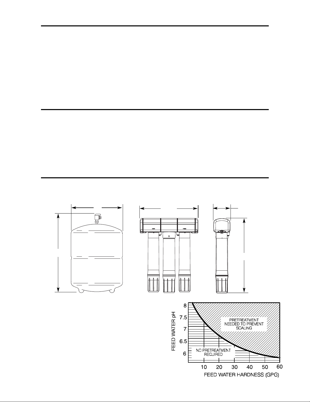
11”
17”
PRETREATMENT OF THE WATER SUPPLY
NEED ED TO PREVENT SCALING
TO USE THE CHART...
12-1/2”
3-1/2”
16”
...Locate the intersecting point of feed water hardness
and pH.
If this point falls within the shaded area, pretreatment* is
needed.
*Softening of the water is the suggested pretreatment.
4
Page 5

WHAT THE DRINKING WATER SYSTEM WILL DO
The drinking water system is a REVERSE OSMOSIS
(RO) water treating unit. Reverse osmosis is a way of
reducing dissolved solids and organic matter from water
by passing it through a special membrane. The membrane separates minerals and impurities from the water,
and they are flushed to the drain. Good tasting, high
quality product water goes directly to the drinking water
faucet, or to the storage area. The system makes a good
supply of drinking water each day (see specifications).
How much it will make depends on the feed water supply pressure, temperature, and quality.
Pre and postfilters are replaceable cartridges. The carbon
prefilter reduces some chlorine (see specifications) while
also filtering sediments. The postfilter reduces any other
undesirable tastes and odors before you use the water.
COMPONENTS OF THE SYSTEM
The RO system consists of:
(1) RO Assembly.
(2) Color coded tubing.
(3) Storage Tank.
(4) Parts bag containing storage tank shutoff valve, drain
flow restrictor, mounting washers and screws.
(5) Hydrolink
its own box (Model HERO-375 only).
(6) Faucet, packaged separately.
INSTALLER PROVIDES: (1) fittings to tap the cold
water pipe for a feed water source to the RO . . . must
adapt to 1/4" tubing; and (2) a drain point for RO discharge water . . . must adapt to 3/8" OD tubing. Both
items must comply with state and /or local codes.
Optional fittings are available from EcoWater for use in
areas where codes permit.
THINGS TO CHECK BEFORE YOU START TO
INSTALL:
« FEED WATER - The water supply to the Drinking
Water System must have the qualities listed in the specifications. If not, it will not make product water as it
should and life of the RO membrane is shortened. City
water most often will have these qualities. Well water
may need conditioning. Have the water tested by a water
analysis laboratory, and get their recommendations for
treatment. Check and comply with local plumbing codes
when providing a water supply to the RO. Refer to Pages
24 and 27.
®
RO Module, with batteries and cable, in
The RO system also includes a standard faucet assembly
to vend the drinking water, and a storage tank.
NOTE: A performance data sheet is included listing
what the system will reduce from the water supply. See
performance data sheet for individual contaminants and
reduction performance.
The drinking water system fits under the kitchen or bathroom sink. However, you can install it where most convenient. You do need a COLD water supply pipe and
drain point within a few feet (6' tubing lengths included).
You can buy longer lengths of tubing if needed to reach
more distant points. Be sure tubing is acceptable for use
on potable water supplies.
NOTE: Codes in the state of Massachusetts require
installation by a licensed plumber, and do not permit the
use of the drain clamp. For installation, use plumbing
code 248-CMR of the Commonwealth of Massachusetts.
CAUTIONS:
Feed water must have chlorine reduced (prefilters reduce
up to amount shown in specifications, Page 4). Chlorine
will destroy the RO membrane cartridge. Be sure to service the prefilters, Page 19.
« DRAIN POINT - A suitable drain point (check your
local plumbing codes) is needed for reject water from the
RO membrane cartridge. Running the RO drain tubing
directly to a floor drain, laundry tub, sump, standpipe,
etc., is preferred. If that is not possible or practical, using
the sink p-trap drain pipe is suggested. A drain clamp
(drilling required), or a special drain adapter are available from EcoWater to use where codes permit. Refer to
Pages 24 and 27. These options install on the sink drain
pipe tailpiece, above the p-trap.
« RO FAUCET - The RO product water faucet installs
on the sink, or on the countertop next to the sink. Often,
it's installed in an existing sink spray attachment hole.
Space is required underneath for tubing to and from the
faucet, and for securing it in place. Refer to Pages 7 and
10.
« MOUNTING SURFACE - The RO assembly mounts
on a wall surface under the sink, or you can lay it on the
bottom of the cabinet. Special washers and screws are
included for wall mounting.When the storage tank is full
of water, it weighs about 30 pounds. Be sure to set on a
surface that will support this weight.
5
Page 6
INSTALLATION - FEED WATER SUPPLY
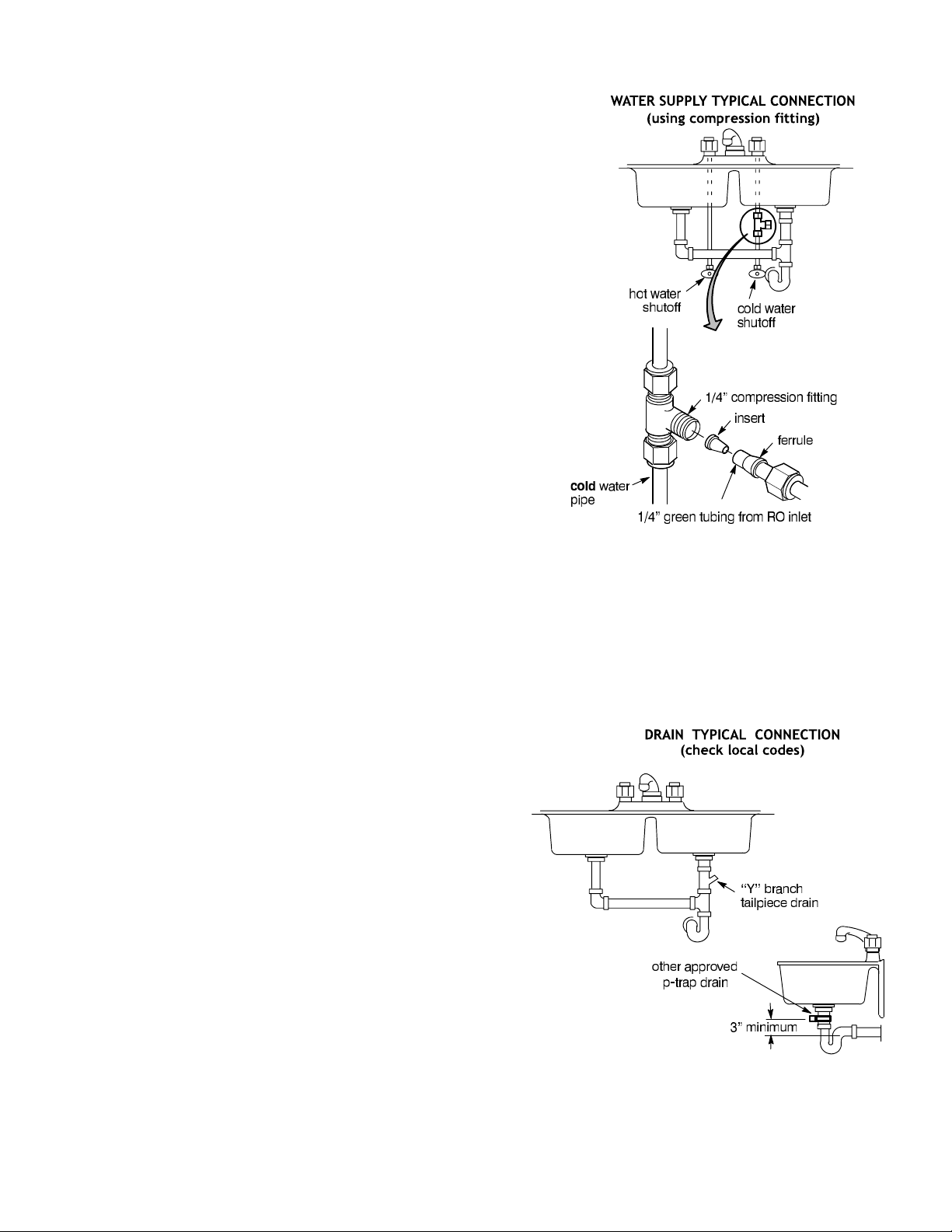
Check and comply with local plumbing codes as you
plan, then install a cold feed (supply) water fitting. The
fitting must provide a leak tight connection to the RO
1/4" OD tubing, see Figure 6, Page 10. A typical installation, using standard plumbing fittings is shown in Figure
1. A saddle valve (not available from EcoWater) may be
used where codes permit. Installation instructions are on
Page 24.
NOTE: Codes in the state of Massachusetts require
installation by a licensed plumber, and do not permit the
use of the drain clamp. For installation, use plumbing
code 248-CMR of the Commonwealth of Massachusetts.
PIPE FITTINGS (compression shown)
IMPORTANT: Before starting, close the hot and cold
water shutoff valves (See Figure 1). Use a pan to catch
water when disassembling the pipe.
Complying with plumbing codes, install a fitting on the
kitchen cold water pipe to adapt 1/4" OD tubing. A typical connection is shown in Figure 1. You can use solder
or threaded fittings. If threaded fittings are used, be sure
to use pipe joint compound or Teflon tape on outside
threads.
FIGURE 1
Do not connect the tubing to the fitting until Step 2, top
of Page 10.
REJECT WATER DRAIN FITTING
Running the RO drain tubing directly to a floor drain,
laundry tub, sump, standpipe, etc., is preferred. If that is
not possible or practical, check and comply with local
plumbing codes as you plan, then install a drain fitting
for RO reject water. This fitting is usually installed at the
sink p-trap (always above). It must provide a leak-tight
connection to 3/8" OD tubing from the RO product water
faucet airgap, see Figure 6, Page 10. Typical drain fitting
installations are listed below. A drain adapter (part no.
7192230) is available to use where codes permit.
Installation instructions are on Page 24. Other options are
shown on Page 27.
“Y” BRANCH TAIL PIECE, OR OTHER
APPROVED P-TRAP DRAIN
Reject water from the RO is routed to the RO faucet airgap (1/4" tubing), then to the drain point with 3/8" OD
tubing. COMPLYING WITH PLUMBING CODES,
install a fitting to accept the 3/8" tubing. Figure 2 shows
typical p-trap and "Y" branch tail piece type drains.
FIGURE 2
Do not connect drain tubing until Step 1, top of Page 10.
6
Page 7
INSTALL THE FAUCET
Select one of the following places to install the faucet.
Be sure there's room underneath so you can make the
needed connections.
u In an existing sink spray attachment hole.
u Drill a hole in the sink top.
u Drill a hole in the countertop, next to the sink.
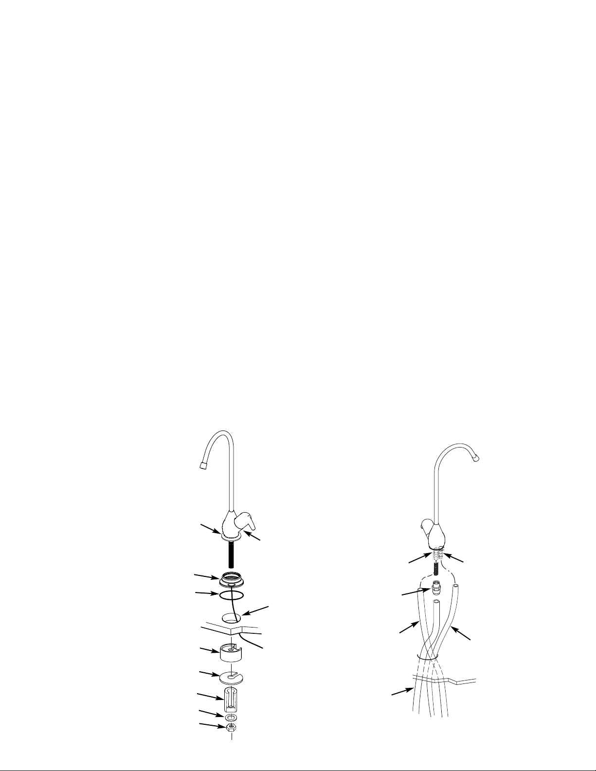
NOTE: Looking at Figure 3, be sure the faucet base will
fit flat against the surface at the selected location so the
o-ring will seal.
1. Do not connect drain tubing until Step 1, top of Page
10.
2. For Model ERO-375, slide the chrome washer onto
the faucet stud, Figure 3.
3. For Model ERO-375E or HERO-375, snap the oring in the groove on the bottom of the ring and slide the
monitor ring onto the faucet stud. The monitor ring LED
wire must be routed through the sink or countertop hole
and through the spacer, if used, Figure 3.
NOTE: If you will route the RO drain tubing directly to
the drain point, disregard Steps 4 and 6 and do Step 1 on
top of Page 10.
4. Take the 30" length of 3/8" black tubing and push
one end onto the 3/8" faucet barb fitting, Figure 4.
5. Move the RO system into position, under the sink.
(Referring to Page 8, hang the system on cabinet wall, or
lay on the floor surface, as desired.)
6. Route the 1/4" red tubing from the bottom, up
through the faucet mounting hole. Push the end of the
tubing onto the 1/4" barb fitting.
7. Work tubing and the faucet stud down, into the
mounting hole.
8. On the underside of the sink or countertop, install
the spacer (Model ERO-375E or HERO-375 only), plastic bushing, flat washer, and hex nut. Slide the large steel
washer in place, between the bushing (or spacer) and the
bottom of the sink or countertop. Then, tighten the hex
nut securely. Make sure that the LED wire is in a position so that it will not be cut, pinched or kinked before
tightening the faucet assembly.
9. Thread the tubing connector onto the bottom of the
faucet stud.
10. Push the end of the 3/8" blue tubing from the RO,
into the tubing connector installed in Step 9.
NOTE: See tubing connection procedures on Page 9. For
ease of service and maintenance, keep tubing lengths
long enough so removal of the RO system from under
the sink is possible.
FIGURE 3 - FAUCET INSTALLATION FIGURE 4 - TUBING CONNECTIONS
¤ Model ERO-375 only
u Model ERO-375E or
HERO-375 only
washer ¤
electronics ring u
o-ring u
spacer u
steel washer
(large)
bushing
washer
hex nut
spout
lever
faucet
1-1/4” dia. hole
wire will be connected to
electronics in manifold
(ERO-375E) or
Hydrolink
in manifold (HERO-375)
®
RO Module
3/8” barb
fitting
tubing connector
1/4” to 3/8”
3/8” black
tubing,
30” long
3/8” blue tubing
from RO
1/4” barb
fitting
1/4” red
tubing
from RO
7
Page 8
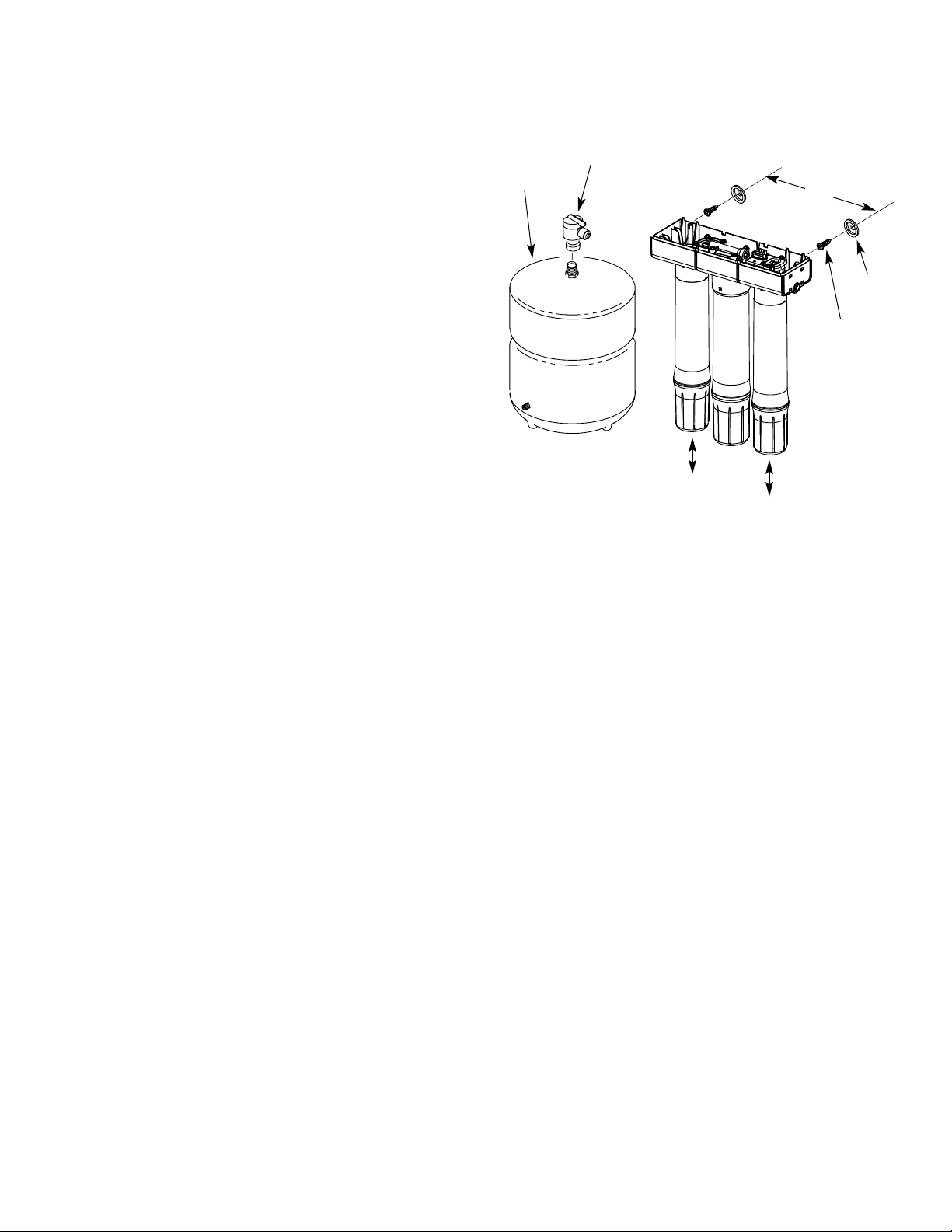
INSTALL RO ASSEMBLY AND STORAGE TANK
1. Hold the RO assembly up to the wall surface where
you will install it. Mark locations for the hanger washers
and screws.
2. Fasten the hanger washers to the wall surface. Wood
screws are included for fastening to a wood surface.
Provide other screws for other surfaces as needed.
3. Hang the RO assembly on the hanger washers.
4. Move the storage tank into place, setting on the floor
surface. Use the stand, included with the tank, and position the tank upright, or on its side.
5. Apply teflon tape on the tank nipple threads and
install the shutoff valve.
6. Model ERO-375E only: Connect telephone style
wire from the monitored faucet to the receptacle on the
electronics board, located on the top of the RO unit.
Route the wire through the strain relief notch on the back
of the manifold.
FIGURE 5
storage
tank
NOTE: Be sure to allow a minimum
space of 4" above the system for
connector (shut
off) valve
removing the top cover to change
batteries (ERO-375E or HERO-375).
9”
hanger
washer (2)
screw (2)
NOTE: Be sure to allow a minimum space of 1-1/2" under the
system for removing the cartridges in order to change them.
8
Page 9
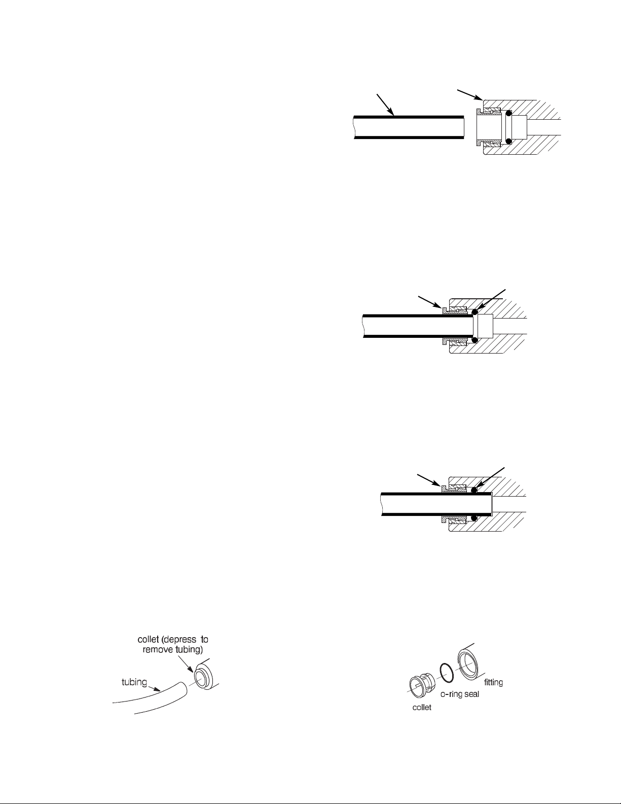
TUBING CONNECTIONS
HOW TO CUT AND CONNECT THE TUBES
Your Reverse Osmosis Water System includes push-in
fittings for quick tubing connection. Review the following instructions before connecting the tubes in the next
step.
Cut tubes to length
1. Use a sharp cutter or knife to cut the end of tubing.
Always cut the tubing square.
2. Inspect the end (about 1") of the tubing to be sure
there are no nicks, scratches or other rough spots. If
needed, cut the tubing again.
NOTE: Tubing lengths should allow for the removal of
the assembly from the hanger washers for servicing. If
tubing lengths are shortened for neater appearance, it
may be necessary to keep the assembly on the hanger
washers for service.
Connect tubes
Tube Correctly Cut
push-in
tube
Cut tubing square with end of tubing round,
smooth, with no cuts, nicks or flat spots.
fitting
Tube Partially Engaged With Fitting
collet
1. Push tubing through collet, until it engages the oring. Continue pushing until the tube bottoms out against
the back of the fitting. A common mistake is to stop
pushing when the tube engages the o-ring. This will lead
to future leaks. When a 1/4” tube is fully engaged,
11/16” of the tube has entered the fitting. When a 3/8”
tube is fully engaged, 3/4” of the tube has entered the fitting.
2. If using tubing other than tubing supplied with the
system, be sure it is of high quality, exact size and roundness with a smooth surface.
To Disconnect Tubes
1. Push the collet inward with a finger tip.
2. Continue holding collet inward while pulling the
tubing out.
Tube Fully Engaged With Fitting
collet
Collet and O-ringDisconnect Tubing
9
Page 10
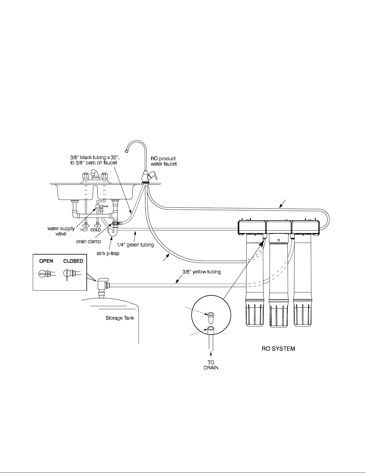
CONNECT WATER SUPPLY, STORAGE TANK AND DRAIN TUBING
drain flow
control insert
(from parts bag)
1/4” red
tubing
Prefilter
PostfilterRO
Membrane
1. Connect faucet drain tubing (if using p-trap
drain): Route the 3/8" black tubing from the 3/8" faucet
barb, to the drain fitting installed on page 6. Keep this
tubing run as straight as possible, without loops, dips or
low-spots. Cut the tubing as needed and fasten to the
drain fitting, securing as required (pages 6 and 24).
Or, connect RO drain tubing (if using floor drain or
other approved drain point): Route the 1/4" red tubing
from the RO to the floor drain, sump, etc. Be sure to provide an air gap when securing in place.
FIGURE 6 - TYPICAL INSTALLATION
2. Install Flow Control Insert: Before connecting the
1/4” red tubing to the RO system manifold’s drain port,
take the flow control insert from the parts bag and insert
it into the end of the tube, as shown below.
3. Connect water supply tubing: Route the length of
1/4 " green tubing from the RO inlet to the feed water
supply fitting, installed on page 6. Connect the tubing as
applies (Figures 1 and 6) and tighten the nut securely.
NOTE: Cut tubing lengths as needed for
neat appearance, but keep long enough for
easier cartridge replacement, see page 19.
3/8” blue tubing to 3/8” quick
connect fitting on faucet stem
1/4” red tubing
from drain port to
1/4” barb on faucet
INSTALL THE FILTER CARTRIDGES
1. Remove the plastic wrap from the prefilter, postfilter
and RO membrane cartridges.
2. Install the cartridges onto the RO system head
assembly, where shown in the figure above. Turn cartridges to the right to tighten.
10
Page 11

SANITIZING THE RO SYSTEM
SANITIZE THE SYSTEM
Sanitizing is recommended immediately after installation
of the Reverse Osmosis system. It’s also recommended
after servicing inner parts. It is important that the person
installing or servicing the system have clean hands while
handling inner parts of the system.
Complete the following steps to sanitize the system.
1. Turn off the water supply to the Reverse Osmosis
system, or remove prefilter to automatically shut off
water supply.
2. Open the Reverse Osmosis faucet. If the tank is not
already empty, allow the water to empty.
3. Use an eyedropper or other suitable tool, and com-
PRESSURE TESTING
DO THE PRECEDING SANITIZING PROCEDURES
BEFORE PRESSURE TESTING.
mon household bleach (5.25%).
4. Add 3 mL. of bleach into open end of yellow tank
tubing. Handle bleach according to bleach manufacturers
recommendations.
5. Connect yellow tank tubing to tank connector. Run
the length of 3/8" yellow tubing from the RO to the connector (shutoff) valve at the top of the storage tank
(Figure 6).
6. Sanitizing the system will be completed during the
pressure test and purging steps below.
NOTE: The bleach must be removed from the system
before drinking the water. See purging instructions
below.
3. Open the shutoff valve on the RO water storage
tank.
1. Open the water supply shutoff valve to the RO.
2. Open the main water supply valve and several house
faucets to purge air from the system. Close faucets when
water runs smooth.
PURGING THE SYSTEM
To purge the system, complete the following steps.
1. Open the RO faucet and let water flow through the
system for a 24 hour period.
NOTE: Water flow may be a slow trickle at this time.
4. In about two hours, pressure will start to build in the
RO system. Then, carefully check all fittings and connections for water leaks. Correct leaks if any are found.
2. Close the RO faucet after the 24 hour purging period
is complete.
3. When the purging is finished, your Reverse Osmosis
system is ready for use.
11
Page 12
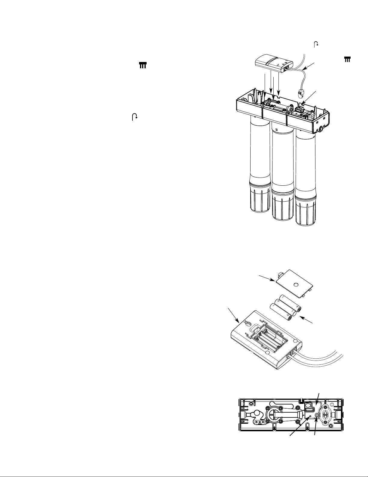
INSTALL THE HYDROLINK®RO MODULE (Model HERO-375 Only)
WIRING CONNECTIONS
1. Locate the cable packed with the Hydrolink®RO
Module. One end should be plugged into the telephonestyle receptacle identified by the RO icon:
2. Plug the other end into the RO electronics receptacle
on the top the RO manifold assembly (See Figure 7).
3. Locate the the wire from the monitored faucet and
plug its connector into the Hydrolink
®
RO Module
receptacle identified by the faucet icon:
NOTE: When installing, or replacing, batteries in the
®
HERO-375’s Hydrolink
module, always make sure that
the module’s cable is already plugged into the RO manifold electronics receptacle (See Figure 7). If the
Hydrolink
®
module’s batteries are installed or changed
while this cable is unplugged, and then the cable is
plugged into the RO electronics while the Hydrolink
®
module is starting up (status light flashing), the RO manifold electronics can be permanently damaged.
FIGURE 7
RO manifold
assembly
Hydrolink
RO Module
Wire from faucet.
Plug into
®
receptacle
Plugged into
receptacle
RO electronics
receptacle
INSTALLING (OR REPLACING) BATTERIES (Model HERO-375 Only)
1. Remove the battery cover from the Hydrolink
Module (See Figure 8).
2. Install three (3) AAA size batteries, making sure that
they are oriented to match the markings inside the battery compartment.
3. Snap the battery cover back in place.
4. When the batteries are first installed at initial start
up, the LED indicator light on the Hydrolink
Module will begin flashing (the LED on the faucet base
will also flash in a red, amber, green sequence).
NOTE: Do not install a coin battery in the holder next to
the LED. The coin battery holder is for systems not
equipped with a Hydrolink
®
RO Module.
®
RO
®
RO
FIGURE 8
Hydrolink
RO Module
FIGURE 9
Battery
Cover
®
3 Batteries
(AAA size)
RO electronics enclosure
12
LED
RESET button
Page 13
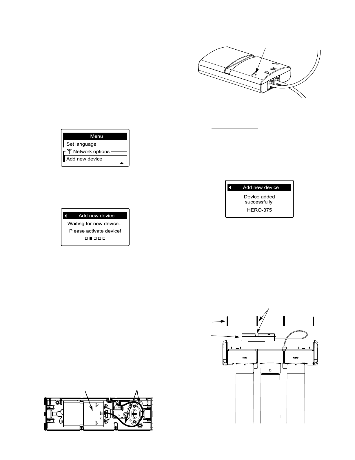
CONNECT THE HYDROLINK®RO MODULE TO THE REMOTE (Model HERO-375 Only)
NOTE: If you do not have a Hydrolink®-equipped water
conditioner (with remote), skip this procedure. The RO
electronics and the indicator light on the faucet base will
function normally, as described on Page 18.
®
1. Locate the remote for your Hydrolink
-equipped
water conditioner or refiner. From any of the rolling status screens, press the SELECT (¡) button to display a
menu.
2. Press the remote’s DOWN (6) button to scroll
through the menu options until Add new device is highlighted.
3. Press the remote’s SELECT (¡) button, and the
screen shown below is displayed. The remote waits two
minutes for the Hydrolink
®
module to be activated (as
described in the next step).
FIGURE 10
Hydrolink
RO Module
®
CONNECT button
(push with ball point pen)
4. Using a ball point pen or similar probe, press the
CONNECT button on the Hydrolink
®
RO Module (See
Figure 10) and hold it down for at least two seconds,
®
until the LED on the Hydrolink
RO Module begins to
flash, then release.
5. When the remote detects a signal from the
®
Hydrolink
RO Module, the display will change to show
the following screen.
POSITION HYDROLINK®RO MODULE UNDER RO COVER (Model HERO-375 Only)
1. Place the Hydrolink®RO Module into the RO mani-
fold assembly, where shown in Figures 11 & 12. Route
the wire as shown in Figure 11 and carefully push it
down into the recesses on the manifold assembly while
holding the Hydrolink
2. Snap the cover onto the RO manifold assembly,
making sure that the Hydrolink
as shown in Figure 12.
FIGURE 11
®
Hydrolink
RO Module
RO Module in place.
®
RO Module is lined up
®
Route wire
as shown
6. If another message appears instead, indicating a
device was not added successfully, press the remote’s
LEFT (
3) button to return to the screen shown under
Step 2. Repeat Steps 3 and 4.
FIGURE 12
Cover
Hydrolink
RO Module
®
Line up when placing Hydrolink
RO Module under cover
®
13
Page 14
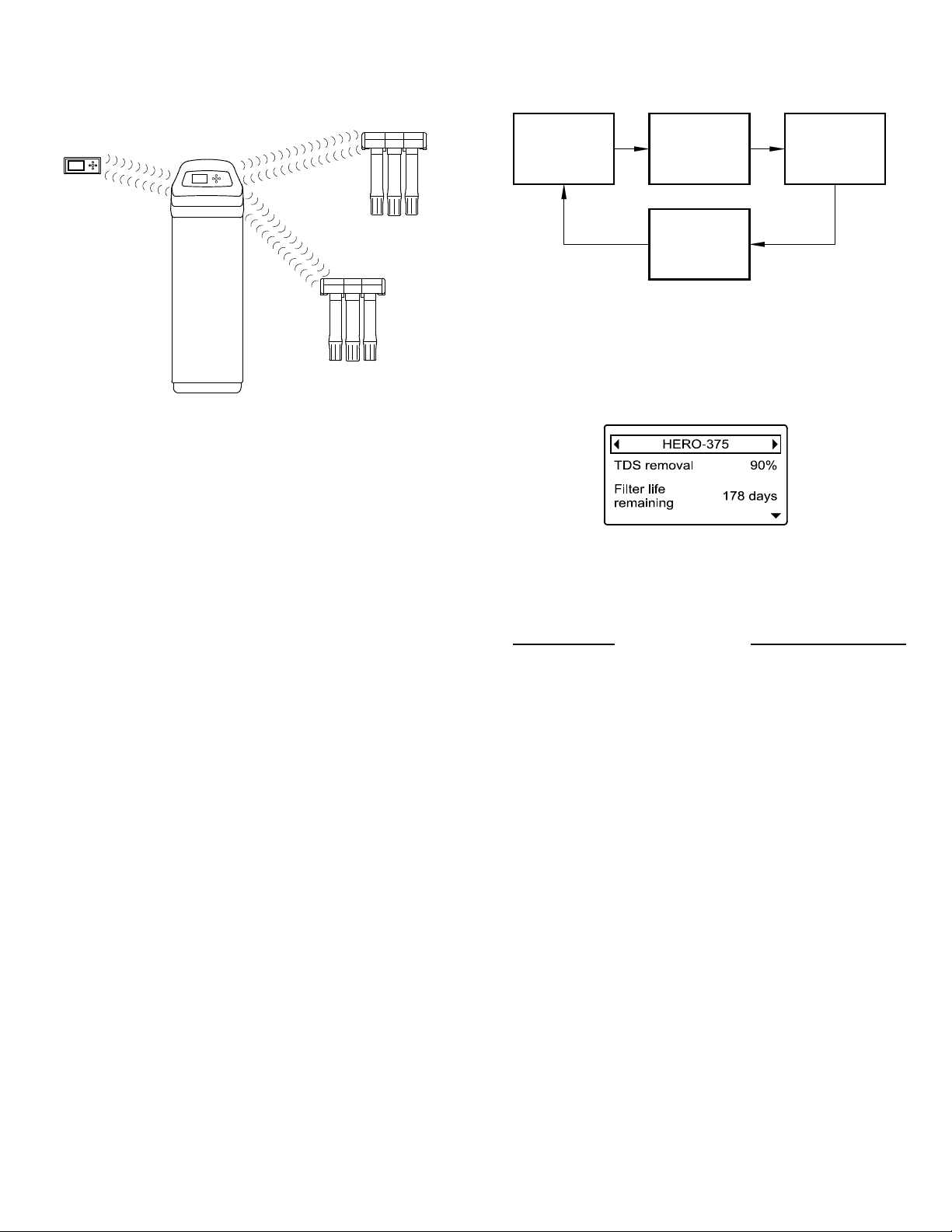
HOW THE HYDROLINK®RO MODULE WORKS (Model HERO-375 Only)
Softener
Remote
Water
System 1
Water
Drinking
Drinking
System 2
Water
System 1
Water
status
System 2
Water
status
Softener
status
Active Alerts
(if any)
Water
Drinking Drinking
FIGURE 13
HYDROLINK®RO MODULE
The EcoWater Systems Hydrolink
®
RO Module is part of
a wireless system which monitors multiple water treatment devices in a home. These water treatment devices
include water softener(s) and drinking water filter(s)
equipped to communicate with this type of system (See
Figure 13). The remote displays, in a convenient, central
location, useful operating information.
Once devices capable of communicating with the system
have been added to the remote (See “Connect the
®
Hydrolink
RO Module to the Remote” on Page 13), the
remote’s normal operating mode displays a sequence of
screens showing the status of each device in the system
(See Figure 14), and any active alerts, such as “Replace
filters.”
HYDROLINK
®
COMMUNICATION SYSTEM
The devices in the system exchange information in a
loosely coupled network. AC powered devices, such as
softeners, listen for new data all the time and act as data
hubs. Battery powered devices like the remote check for
information at regular intervals. Battery powered
devices like drinking water systems do not communicate
directly with each other or the remote, but pass along
information through AC powered devices. Up to 6
devices may be added to one remote, including no more
than 3 EcoWater Systems 3500 series water softeners.
An AC powered device with a transmitter must be part of
any network (usually a water softener).
It is not necessary for every device in a network to be in
radio range of all others. Information one device communicates to any other device will be passed along (like
gossip) to all devices in the network.
14
FIGURE 14
STATUS SCREEN ON REMOTE
®
When the Hydrolink
RO Module has been connected to
the remote it will have a status screen on the remote that
alternates with other devices in the system as shown
above.
The normal status screen will look like the one shown
above, and will display the following data items from the
RO:
REMOTE DISPLAY
DATA ITEM
=TDS* removal (%) . . . . . . . . . . . . . . 2 hours
=Filter life remaining (days) . . . . . . . . 2 hours
=Average daily use (gallons/liters) . . . 2 hours
=Water dispensed** (gallons/liters) . . 2 hours
UPDATED EVERY
*Total dissolved solids.
**Water output through faucet since the last filter
change, not including water currently stored in tank.
Use the remote’s DOWN (6) and UP (5) buttons to
scroll through the entire list of items.
ACTIVE ALERTS
The normal status screen, described above, will not be
displayed in a rolling sequence when one of the following active alert messages is displayed:
=Replace filters (See Page 19 for filter replacement
instructions)
=Replace membrane (See Page 19 for membrane
replacement instructions)
=Replace batteries (See Page 12 for battery replace-
ment instructions)
=No RO system found (May indicate that the cable
between the Hydrolink
®
Module and RO electronics
is not properly connected, as shown on Page 12).
Page 15
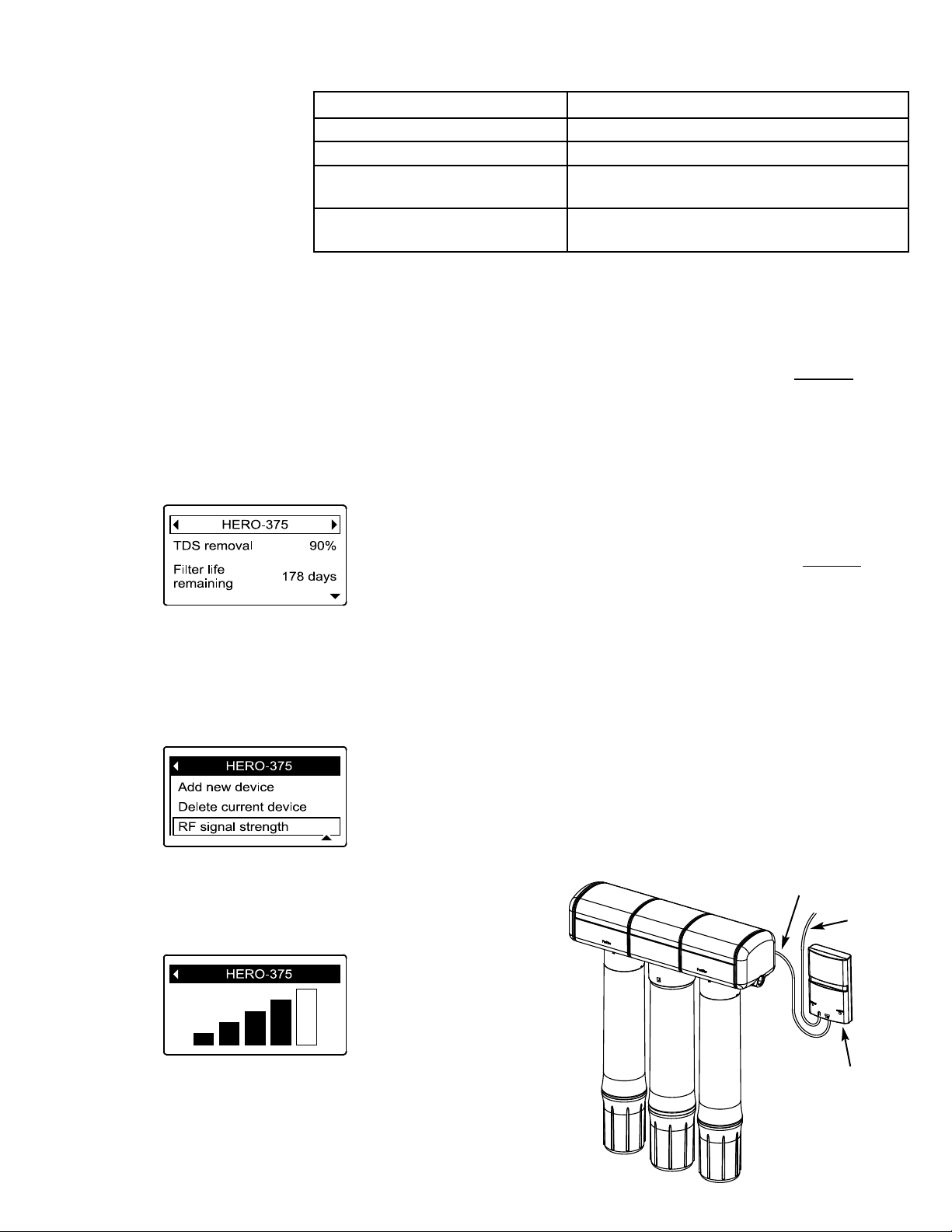
STATUS LED ON THE HYDROLINK®RO MODULE (Model HERO-375 Only)
The LED on the Hydrolink
RO Module indicates status of
the unit’s operations, as shown
in the table:
®
LED Indication Status
Not Flashing Batteries dead or RO electronics not detected
Short Flash every 15 seconds Normal operation
Steady Flashing once per second
Fast Flashing (twice per second)
for 5 seconds
CHECKING THE RF SIGNAL STRENGTH (Model HERO-375 Only)
After the Hydrolink
remote, it is useful to check the signal strength on the
remote:
1. Have the remote in its intended location.
2. Press the remote’s RIGHT (4) or LEFT (3) buttons
to advance to the status screen for the HERO-375.
3. With the HERO-375 status screen displayed, press
the SELECT (¡) button to display the HERO-375 menu.
4. Press the DOWN (
menu options until RF signal strength is highlighted in
a box (as shown below).
®
RO Module has been added to the
6) button to scroll through the
Busy (normal at startup and when connecting
to remote)
Error (RO electronics not detected)
If the signal strength is weak (2 bars or less on the display), check the RF signal strength of the softener
described on Page 14 (Hydrolink
®
Communication
. As
System), during normal operation the RO communicates
indirectly with the remote, using the softener to relay
information. Checking the signal between the softener
and remote may help to identify which is the “weak link”
in the chain.
Check the softener’s RF signal strength by going back to
the rolling status screens, advancing to the softener
status
screen, pressing SELECT (¡) and repeating steps 4 and
5. Since the RO communicates with the remote through
the softener, the link between the softener and remote
may be the weak one. Remedies for low signal strength
include moving the remote to a different location and
checking again.
If the signal strength of the RO is very weak compared
with the softener’s signal, it may be necessary to take the
Hydrolink
®
RO Module out from under the RO system
cover and mount it to the wall vertically (See Figure 15)
There is a recess on the back of the module for hanging
it from a fastener (not included).
5. Press the SELECT (¡) button, and the screen shown
below will appear. The more bars that are filled in black,
the stronger the signal. The signal strength display
updates every 15 seconds.
6. To exit this screen, press the LEFT (3) button.
FIGURE 15
Feed wire through slit in
rear panel of RO cabinet
Faucet
wire
Mount Hydrolink
Module vertically
®
15
RO
Page 16
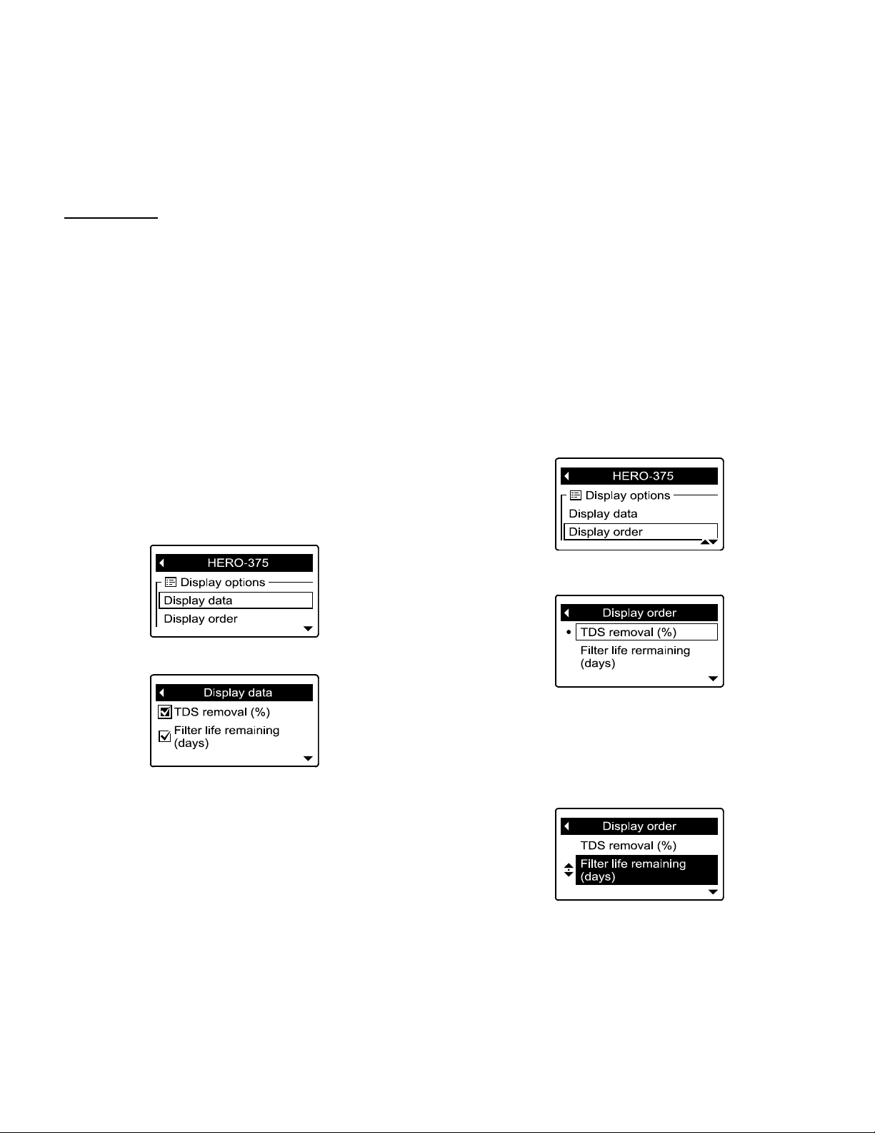
CHANGING THE REMOTE DISPLAY (Model HERO-375 Only)
CHANGING WHICH DATA ITEMS ARE DISPLAYED IN THE STATUS SCREEN
The HERO-375 status screen on the remote (See Page
14) may be customized to turn on or off any or all of the
items listed below:
DATA ITEM
=TDS* removal (%)
=Filter life remaining (days)
=Average daily use (gallons/liters)
=Water dispensed** (gallons/liters)
*Total dissolved solids.
**Water output through faucet since the last filter
change, not including water currently stored in tank.
To turn data items on or off:
1. Press the remote’s LEFT (3) or RIGHT (4) buttons
to manually advance to the HERO-375 status screen.
2. Press the remote’s SELECT (¡) button to display
the HERO-375 menu.
3. Press the DOWN (6) button to scroll through the
menu until Display data is highlighted in a box.
NOTE: If you turn off all data items, there will still be a
status screen for the HERO-375 on the remote, but it will
be blank below the header.
CHANGING THE ORDER OF DATA ITEMS DISPLAYED IN THE STATUS SCREEN
In addition to changing which data items the remote displays during normal operation, the order of these items
may be customized, as follows:
1. Press the remote’s LEFT (
3) or RIGHT (4) buttons
to manually advance to the HERO-375 status screen.
2. Press the remote’s SELECT (
¡) button to display
the HERO-375 menu.
3. Press the DOWN (6) button to scroll through the
menu until Display order is highlighted in a box.
4. Press the SELECT (
¡) button to display the display
data screen.
5. Press the DOWN (6) or UP (5) buttons to scroll
through the list of display data items. Items with a check
mark in the box next to them will be displayed during
normal operation.
6. To select an unchecked display data item, make sure
the box next to the item’s name is highlighted (box is
black inside). Then press the SELECT (
¡) button. The
check mark will appear in the box.
7. To un-select a checked display data item, make sure
the box next to the item’s name is highlighted (box is
black inside). Then press the SELECT (
¡) button. The
check mark will disappear.
8. When selections are complete, exit this menu by
pressing the LEFT (3) button twice.
4. Press the SELECT (
¡) button to display the display
order screen.
5. Press the DOWN (
6) or UP (5) buttons to scroll
through the list of display data items. Stop when the
item you want to move is highlighted in a box.
6. Press the SELECT (¡) button. Arrows will appear
next to the item.
7. Press the UP (5) or DOWN (6) buttons to move
the item higher or lower in the list.
8. When the item is where you want it in the list, press
the SELECT (
¡) button. The arrows next to the item
will disappear.
9. To move another item, return to Step 5. When fin-
ished moving items, press the LEFT (
3) button twice.
16
Page 17
CHANGING THE REMOTE DISPLAY (Model HERO-375 Only)
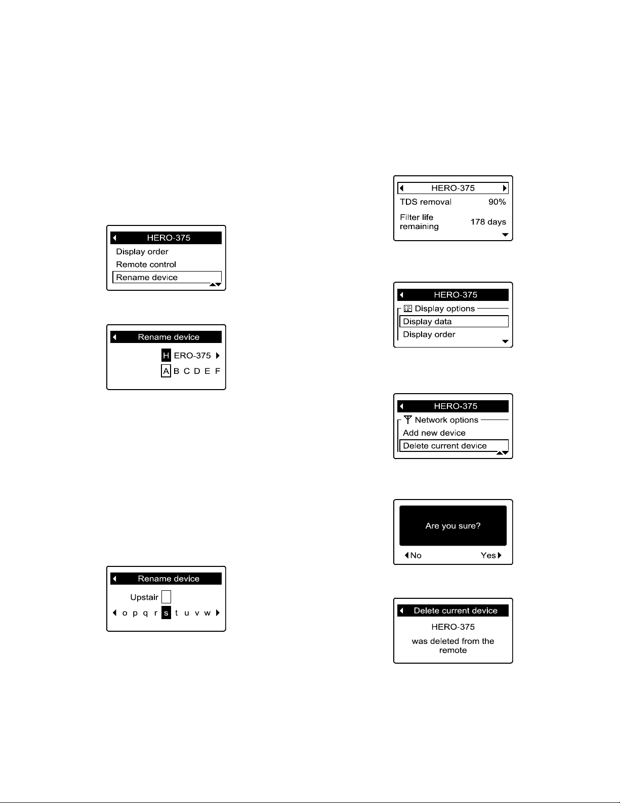
RENAMING A DEVICE
“HERO-375” is the default name in the RO status screen
on the remote. This name may be customized (up to 20
characters long) as follows:
1. Press the remote’s LEFT (
3) or RIGHT (4) buttons
to manually advance to the HERO-375 status screen.
2. Press the remote’s SELECT (¡) button to display
the HERO-375 menu.
3. Press the DOWN (6) button to scroll through the
menu until Rename device is highlighted in a box.
4. Press the SELECT (
¡) button to display the rename
device screen.
DELETING A DEVICE
To delete a device from the remote (possible reasons for
deleting a device include replacing or upgrading the
Hydrolink®RO Module):
1. Press the remote’s LEFT (3) or RIGHT (4) buttons
to manually advance to the status screen for the device to
delete. The device name will show in the header.
2. Press the remote’s SELECT (¡) button to display
the device menu.
5. Two lines are displayed below the header. The
upper line shows the device name. The lower line is the
list of available characters (upper and lower case alphabets, space character, numbers and common punctuation
marks). Use the RIGHT (
4) or LEFT (3) buttons to
highlight the first character you want to replace in the
old device name.
6. Press DOWN (6) to switch to the lower line.
7. Press the RIGHT (4) or LEFT (3) buttons to scroll
through the character list. Stop when the character you
want to select is highlighted.
8. Press the SELECT (
¡) button. The character you
picked is added to the upper line.
3. Press the DOWN (6) button to scroll through the
menu options until Delete current device is highlighted
in a box.
4. Press the SELECT (¡) button. The following screen
will appear.
5. Press the RIGHT (
4) button. The following screen
will appear.
9. To select the next character, return to Step 7. When
finished entering the device name, press the UP (5) button to switch to the upper line, then press SELECT (
¡)
followed by LEFT (3).
6. To exit this screen, press the LEFT (
3) button.
17
Page 18
HOW THE RO SYSTEM WORKS
PREFILTER
Water from the cold supply pipe enters the RO assembly
sediment prefilter first. The replaceable sediment cartridge reduces chlorine, sand, silt, dirt, other sediments to
clean the feed water before entering the RO cartridge and
postfilter.
REVERSE OSMOSIS (RO) CARTRIDGE
The cartridge, inside the RO housing, includes a tightly
wound, special membrane. Water is forced through the
cartridge and the membrane reduces the dissolved solids
and organic matter. High quality product water exits the
RO housing and goes to the storage tank, or to the postfilter and RO faucet. Reject water, with the dissolved
solids and organic matter, is routed through the flow control and to the drain.
STORAGE TANK
The storage tank holds product water. A diaphragm
inside the tank keeps water pressurized when the tank is
full, to provide fast flow from the RO faucet. The tank is
charged with 5-7 psi air.
POSTFILTER
After leaving the storage tank, but before going to the
RO faucet, product water goes through the postfilter. The
postfilter is an activated carbon type filter. Any remaining tastes, odors and sediments are reduced from the
product water. Clean, high quality drinking water is
available for use.
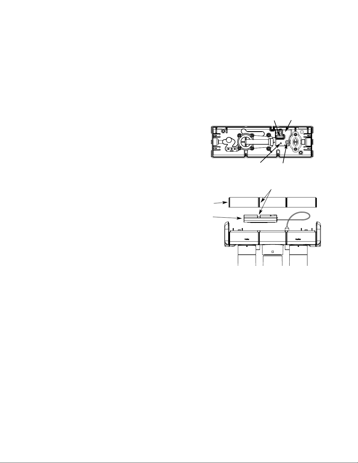
sequence. All timers and counters are reset to zero. In
order to reset the time and gallon count feature, push the
the button on the RO electronics enclosure and hold until
the LED flashes, then release.
Model ERO-375E only: the battery needs to be replaced
at the time of filter replacement. Use only lithium batteries (CR 2032). Improper placement of battery could
damage electronics. Use care when inserting the battery
to align it correctly on the PWA with proper polarity.
FIGURE 16
FIGURE 17
Cover
Hydrolink
RO Module
(HERO-375
only)
Battery (ERO-375E only)
®
LED
RO electronics enclosure
RESET button
Line up when placing Hydrolink
RO Module under cover
®
FAUCET
The sink or countertop faucet vends the drinking water
when opened. It is opened and closed by turning the
knob.To comply with plumbing codes, an air-gap is built
into the faucet drain water connection.
ELECTRONICS (ERO-375E or HERO-375)
The RO system will monitor the total product flow of the
unit and also length of time the filters have been
installed. The faucet base has an indicator light that
flashes to inform you of the status of the RO membrane
and filters.
Green - RO membrane and filters are good.
Amber - Warning, filters need replacing. Filters need
replacing, when water has been drawn, after 6 months
time (or 650 gallons have been used).
Red - RO membrane needs to be replaced.
When the batteries are first installed at initial start up, the
LED indicator light will flash in a red, amber, green
18
SHUTOFF ASSEMBLY
To conserve water, the drinking water system has an
automatic shutoff system. When the storage tank has
filled to capacity, and the drinking water faucet is closed,
pressure closes the shutoff to stop flow into the RO.
After drinking water is used, and pressure in the system
drops, the shutoff opens to allow water flow again.
CHECK VALVE
A check valve is located in the RO manifold, above the
center cartridge. The check valve prevents a backward
flow of product water from the storage tank. A backward
flow could rupture the RO membrane.
FLOW CONTROL
Water flow through the RO membrane is regulated by the
flow control. It maintains the desired flow rate to obtain
the highest quality drinking water. The flow control is
located in the 1/4" red drain tube. A small cone-shaped
screen fits over the end of the flow control to help prevent plugging with drain water sediments.
Page 19
CARE OF YOUR REVERSE OSMOSIS SYSTEM
To keep your reverse osmosis system operating and producing high quality water, you must make sure supply
water is always within the limits shown in the specifications. Good supply water helps to assure longer life from
the RO membrane cartridge, prefilter and postfilter cartridges. However, each of these will wear out in time and
need replacement.
This reverse osmosis system contains a replaceable
treatment component critical for effective reduction
of total dissolved solids. The monitor faucet feature
provides continuous analysis of the systems performance. For systems not equipped with the monitor faucet function, it is highly recommended that
you have your water tested at least every 6 months
to verify your system is performing properly. Test
kits are available by calling 1-800-949-8220, or
check the water testing section of your local phone
directory.
If the RO assembly is wall mounted, you may be able to
replace parts with the assembly left on the wall. If not,
simply lift the RO assembly from the mounting washers
and lay on the cabinet floor when replacing the prefilter
and post filter cartridges and RO membrane.
FIGURE 18
PREFILTER AND POST FILTER CARTRIDGES
You must replace the prefilter cartridge often to protect
the RO membrane from being destroyed by chlorine,
and/or from plugging with sediments in your water supply. If the water supply contains both chlorine and sediments, replace the prefilter cartridge at least every 6
months of product water use. Replace more often than 6
months if it begins to plug with sediments.
If the water has sediments only, with no chlorine, you
may notice a slower making of product water as the prefilter collects the sediments. When this occurs, replace
the prefilter cartridge. Also replace the post filter cartridge.
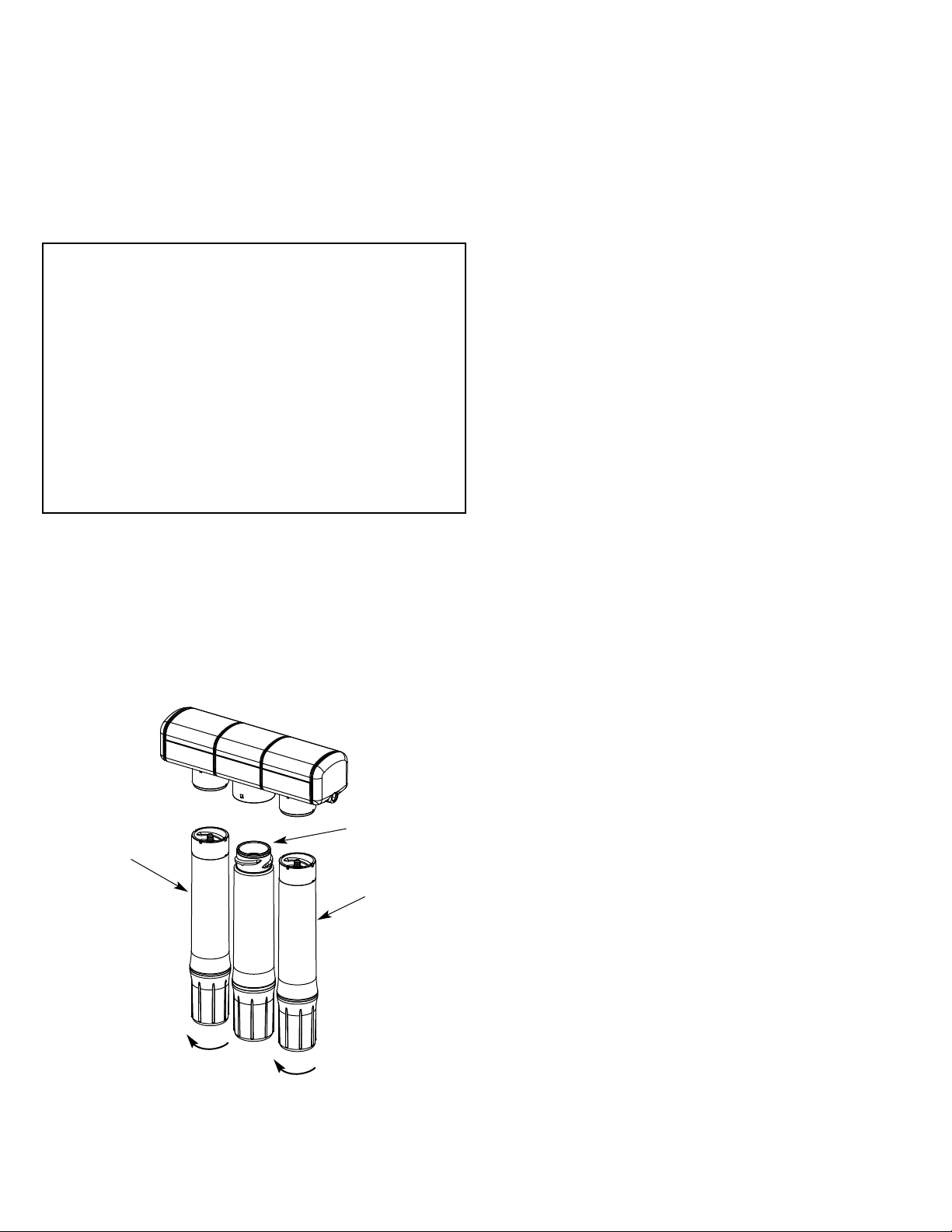
To replace the filter cartridges, see Figure 18:
1. Remove (turn to the left) the prefilter cartridge from
the filter head.
2. Remove the postfilter cartridge (turn to the left) the
postfilter cartridge from the filter head.
3. Discard both cartridges in a proper manner.
4. Insert new cartridges, starting with the post filter,
turning to the right to reattach the cartridges.
5. Model ERO-375E only: replace the battery with new
(CR 2032 or equivalent).
6. On the ERO-375E or HERO-375, press and hold the
button on the RO electronics enclosure until the green
light begins flashing. Release the button during the 3 seconds that the light flashes.
7. It is recommended to discard the first full tank after
the filters have been changed to minimize carbon fines.
prefilter
cartridge
remove
Turn cartridges in the direction of
the arrow to remove. Turn them
in the opposite direction to install.
remove
RO cartridge
postfilter
cartridge
RO MEMBRANE CARTRIDGE
This reverse osmosis system contains a replaceable component critical to the efficiency of the system.
Replacement of the reverse osmosis component should
be one with identical specifications, as defined by the
manufacturer, to assure the same efficiency and contaminant reduction performance.
The life of the RO membrane cartridge depends mostly
on the pH and hardness of the supply water to the RO
system (see specifications). Cartridge life is shorter with
higher pH. For example, if supply water pH is from 6.8
to 7.7, the cartridge may last for well over one year.
However, cartridge life may be as short as 6 months if
the pH is as high as 8.5 to 10. Higher pH weakens the
cartridge membrane and causes pin-hole leaks.
It's time to replace the RO cartridge when the red LED
continued on Page 20
19
Page 20
CARE OF YOUR REVERSE OSMOSIS SYSTEM
continued from Page 19
flashes or the production rate and/or quality of product
water drops. Product water may begin to taste different
or bad, indicating solids and organics are passing through
the RO membrane. When replacing the RO cartridge,
replace the prefilter and postfilter cartridges as well.
To replace the RO cartridge (see Figure 18):
1. Remove (turn to the left) the pre filter cartridge from
the filter head to relieve pressure on the Reverse
Osmosis cartridge.
2. Remove the RO cartridge.
3. Remove the post filter cartridge.
4. Discard the cartridges in a proper manner.
5. Install new cartridges in reverse order (post filter,
Reverse Osmosis and then prefilter). Turn cartridges to
the right to re-attach to the filter heads.
6. Model ERO-375E only: replace the battery with new
(CR 2032 or equivalent).
7. On the ERO-375E or HERO-375, press and hold the
button on the RO electronics enclosure until the green
light begins flashing. Release the button during the 3 seconds that the light flashes.
8. Purge the RO membrane cartridge following instructions on Page 11.
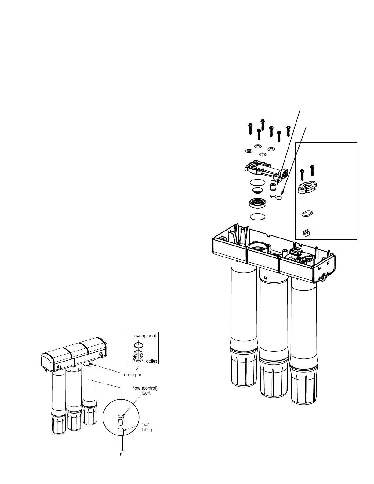
AUTOMATIC SHUTOFF / PADDLEWHEEL
SERVICE
If either the shutoff assembly or paddlewheel requires
service, be sure to reassemble parts exactly as shown
below.
FIGURE 20
check valve, assemble
into shut off cover
o-ring (2) assemble
onto manifold
screw (6)
washer (4)
automatic
shutoff cover
diaphragm
plunger
spacer ring
diaphragm
ERO-375E or
HERO-375
screw (2)
paddlewheel
cover
o-ring
paddlewheel
FLOW CONTROL
The flow control is vital for proper operation of the RO
membrane cartridge. The control keeps water flow
through the membrane at the needed rate to obtain the
best quality product water.
Periodically check the flow control to be sure the small
hole through it is clean and unrestricted.
FIGURE 19
20
TO
DRAIN
Page 21
CARE OF YOUR REVERSE OSMOSIS SYSTEM
FILTER CHANGE ALERT LED (ERO-375E or
HERO-375)
The ERO375E and HERO-375 provide the option of
alerting you to the need for a filter change at either 6 or
12 month intervals. The timer is factory set to 6 months.
The recommended interval is 6 months, but certain water
conditions may allow a 12 month setting. Consult a
water professional to determine the proper interval.
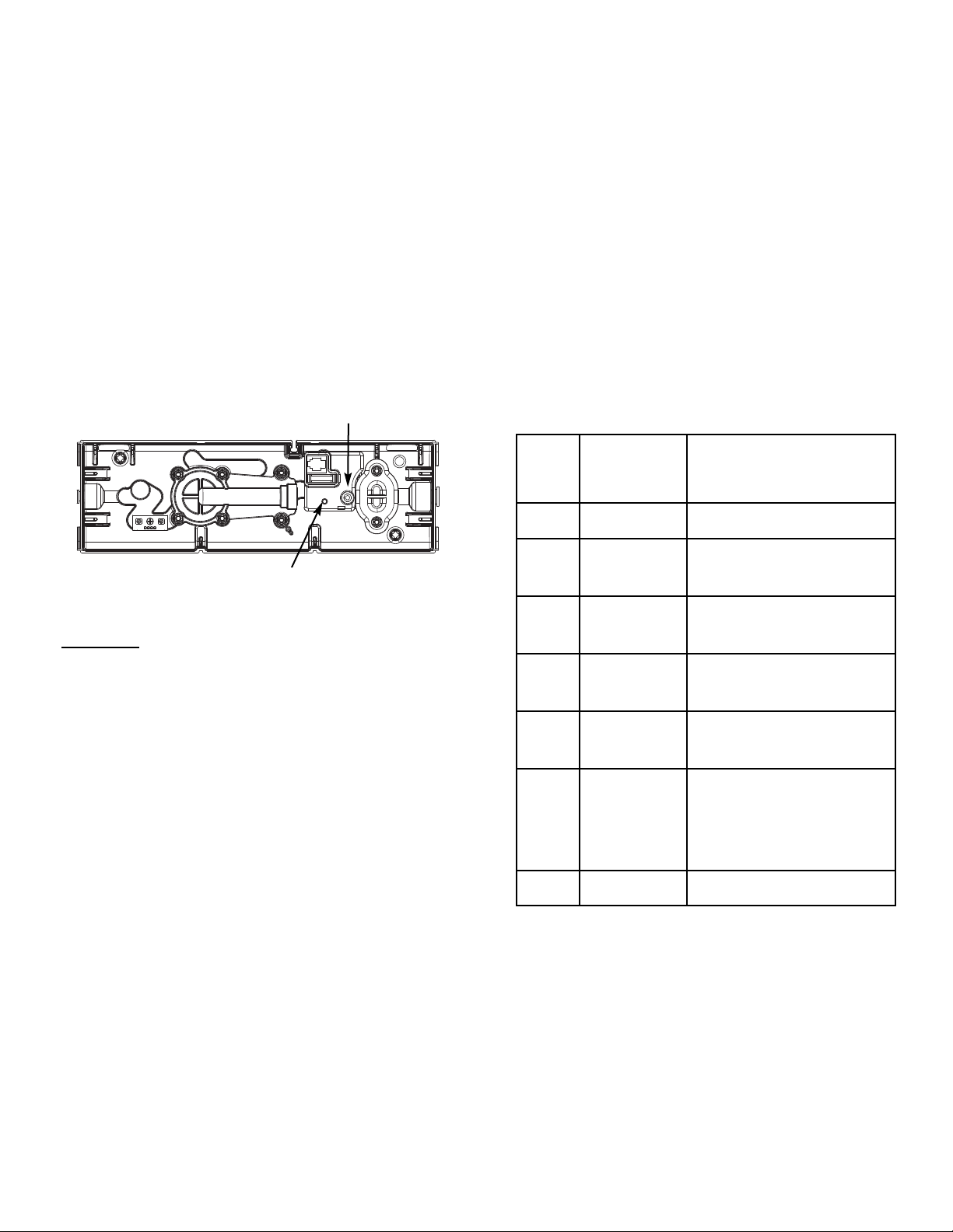
NOTE: Please read the following 3 steps and study the
order of events in the table at right before starting.
1. Remove the top cover and locate the RESET button
on the PWA board.
FIGURE 21
LED
RESET button
2. To change from 6 to 12 months, press and continue
to hold down
the RESET button. Watch the LED dur-
ing this process. The LED will go on steady, then flicker, then go off for 6 seconds (See chart at right). When
the LED begins to blink (after button has been held
down for about 12 seconds), immediately release the button.
3. Once the button is released, the LED will show several double blinks to indicate that the timer has been set
to 12 months.
To change back to 6 months:
To change the unit back to 6 months, repeat the
sequence, holding down the RESET button for 12-15
seconds, until the light begins to blink. Once the button
is released, the light will show several single blinks to
indicate that the timer has been set to 6 months.
Order
1 -
2
3
4
5
6 -
7 -
RESET
Button
Press
& Hold
Continue
Holding
Continue
Holding
Release
Now
LED
l OFF
¡ ON (Steady)
ï¡ðFlicker
l OFF (for 6 sec.)
ï¡ðSingle Blink or
Double Blink
ï¡ðDouble Blink
(set for 12 mo.)
or Single Blink
(set for 6 mo.)
l OFF
21
Page 22
CARE OF YOUR REVERSE OSMOSIS SYSTEM
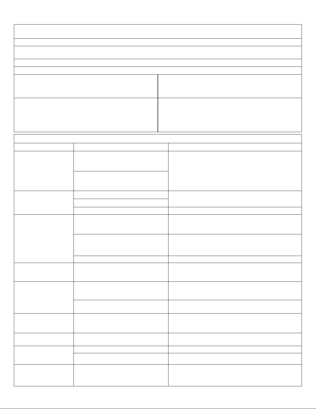
REVERSE OSMOSIS SYSTEM CARE GUIDE
MODEL NOs. ERO-375, ERO-375E & HERO-375
1. AT LEAST every 6 months, replace the prefilter and postfilter cartridges or when yellow LED flashes or remote indicates “Replace filters”.
2. Replace the RO membrane cartridge when the percent rejection of total dissolved solids (TDS) is less than shown in the specifications
(see B, below) or when red LED flashes or remote indicates “Replace membrane”.
3. Replace the batteries once per year or when remote indicates “Replace batteries”.
If any of the following occur before the 6 months, replace as directed.
A. Slow Making of Product Water: Replace the prefilter cartridge. If the
production rate does not improve, replace the post filter cartridge and RO
membrane cartridge.
B. High Total Dissolved Solids (TDS) in Product Water: If water quality is in
question, contact your local dealer for testing. It is important to test both
the treated and untreated water to determine system performance. If the
TDS is not within the system's performance guidelines, replace the prefilter, post filter and RO membrane cartridges.
OTHER TROUBLESHOOTING
PROBLEM CAUSE CORRECTION
Chlorine taste and/or odor
in the RO product water.
The amount of chlorine in your water supply exceeds maximum limits, and has
destroyed the RO membrane.
The prefilter is no longer removing chlorine
from the water supply.
C. Chlorine Taste and/or Odor: Replace the prefilter, post filter and RO
membrane cartridges.
If the water supply contains more than 2.0 ppm of chlorine,
additional filtering of the water supply to the RO is needed.
Correct this condition before doing maintenance on the RO
system.
Replace the prefilter, post filter and RO membrane cartridges.
Other taste and/or odor. Post filter expended. Replace the post filter cartridge. If taste and odor persists,
RO membrane cartridge expended.
replace the prefilter cartridge and RO membrane cartridge.
Contamination in product water storage. Use sanitizing procedures. Replace the post filter cartridge.
System makes product
water too slowly.
Water supply to the RO system not within
specifications.
Prefilter or RO membrane cartridges
plugged with sediments or fouled.
Increase water pressure, precondition the water, etc., as needed to conform before doing maintenance on the RO system.
Replace the prefilter cartridge. If rate does not increase,
replace the postfilter cartridge and RO membrane cartridge.
Flow Control Insert plugged. Check and clean Flow Control Insert.
System makes lower
amount of product water
than usual.
High total dissolved solids
(TDS) in product water -
Storage tank air-charge less than 5 - 7 psi. Open RO faucet and drain tank until flow slows to a drip.
Keep faucet open and check tank pressure. If low, pressurize
to 6 psi. Close faucet to refill the tank.
Water supply to the RO system not within
specifications.
Increase water pressure, precondition the water, etc., as need-
ed to conform before doing maintenance on the RO system.
flashing red LED.
RO membrane cartridge expended. Replace the prefilter, postfilter and RO membrane cartridges,
flow control, and screen.
Water leaking from faucet
airgap hole.
Drain side of faucet airgap (3/8” tubing)
plugged, restricted, or incorrectly connected
Inspect and eliminate restriction or plug. Refer to installation
instructions for proper drain connection.
to drain point.
Continual water flow to
drain.
Faucet LED indicator light
does not function after bat-
Check valve or automatic shutoff assembly
Clean, repair or replace as needed.
plugged, restricted or parts worn.
Battery dead. Replace with new battery.
Battery installed incorrectly. Install battery correctly.
tery change.
Continual high water flow
to drain and no product
Missing flow restrictor in red drain tube or
its corresponding port.
Replace flow restrictor.
water.
22
Page 23
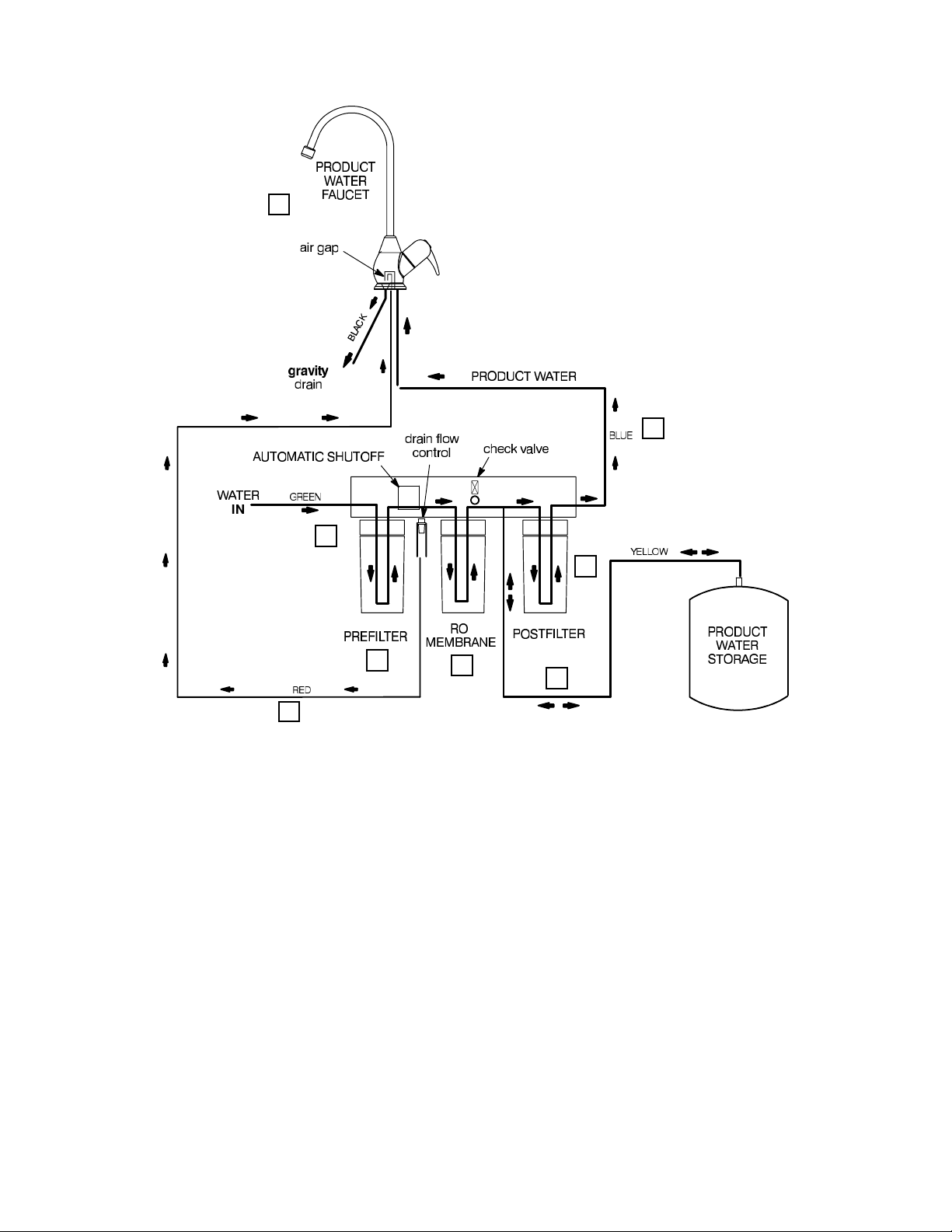
FIGURE 22
REVERSE OSMOSIS SCHEMATIC
6
8
1
7
2
5
3
4
Water Flow Description
1. Water enters prefilter. Sand, silt and other sediments are reduced. Chlorine is also reduced.
2. Water leaves prefilter and proceeds to the Reverse Osmosis Cartridge.
3. Water enters the Reverse Osmosis membrane. Dissolved solids are reduced.
4. Processed water leaves the Reverse Osmosis Membrane and flows to the storage tank.
5. Waste water with dissolved solids leave the Reverse Osmosis membrane and flows to the drain.
6. Faucet is activated.
7. Processed water leaves the storage tank and flows to the post filter filtered to ensure fresh taste.
8. Water flows to the Reverse Osmosis faucet.
23
Page 24
INSTALLATION OF OPTIONAL FITTINGS (not included)
SADDLE VALVE, not available from EcoWater
NOTE: This type of valve pierces a hole in copper tub-
ing or plastic pipe. If installing on iron pipe, you have to
drill a 1/8" pilot hole for the piercing pin. Be sure to turn
off water to the pipe and to drain water from it before
drilling. READ THE FOLLOWING DANGER NOTE.
DANGER (IF DRILLING METAL PIPE): To protect
yourself from serious injury or fatal shock, use a battery
powered hand drill only to make the hole. Do not use an
electric drill.
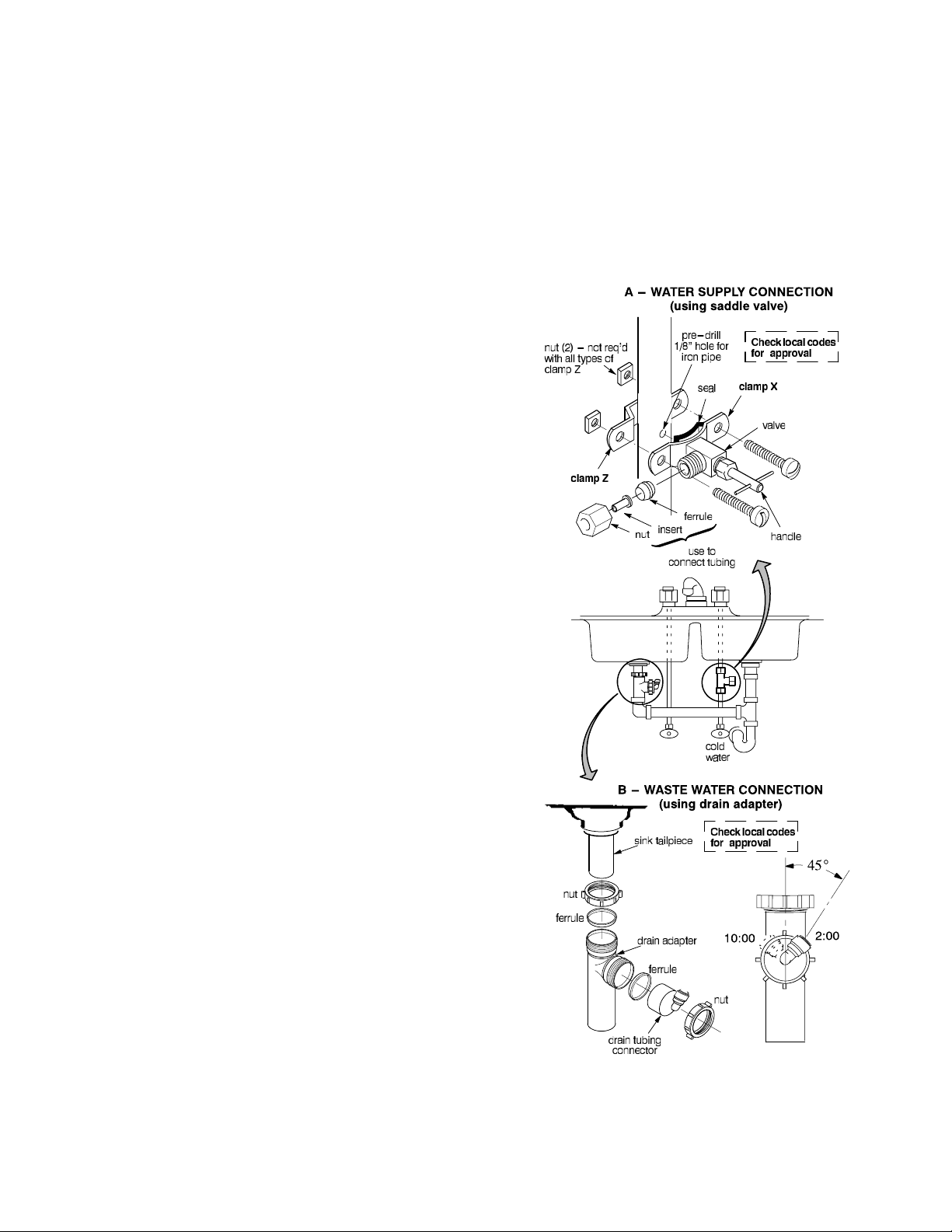
1. Looking at Figure 23, turn the valve into clamp X
and tighten (may be preassembled). Turn the valve handle all the way out.
2. Place the seal on the inside of clamp X as shown. Be
sure the piercing pin does not stick out beyond the seal.
3.Place clamp X and Z around the pipe and secure in
place with two screws. Tighten both screws evenly, but
do not overtighten. Clamp Z will either have threaded
screw holes, or two nuts are included.
3. Install the drain adapter onto the sink tailpiece, using
a ferrule and nut. Snug the nut, but do not tighten.
4. Assemble the p-trap to the drain adapter, and other
drain pipe fittings as required (check codes) to complete
the drain run.
5. Tighten all connections, but do not overtighten and
break plastic fittings.
FIGURE 23
4. Carefully turn the handle inward to pierce a hole in
the copper or plastic pipe.
DRAIN ADAPTER, part no. 7192230
¢ The optional drain adapter installs in the sink drain
pipe, always above or ahead of the p-trap. Be sure to
comply with your local plumbing codes. Other drain pipe
fittings, in addition to the adapter, may be needed.
¢ The drain adapter fits 1-1/2" sink drain pipe.
¢ The adapter installs directly onto the sink tailpiece as
typically shown in Figure 23.
¢ Locate so drain tubing from the faucet makes a
straight run to the adapter, without dips, loops, low spots
or kinks.
NOTE: Consult a plumber if you are not familiar with
plumbing procedures.
1. Use a ferrule and nut to assemble the drain tubing
connector to the drain adapter. Turn the connector to
about 45° from the 12:00 position, as shown (to 10:00 or
2:00 position as needed). Tighten the nut securely.
2. Carefully disassemble the sink drain pipe and clean
the tailpiece to assure a leak-tight fit.
24
NOTE: Codes in the state of Massachusetts require
installation by a licensed plumber, and do not permit the
use of a saddle valve. For installation, use plumbing code
248-CMR of the Commonwealth of Massachusetts.
Page 25
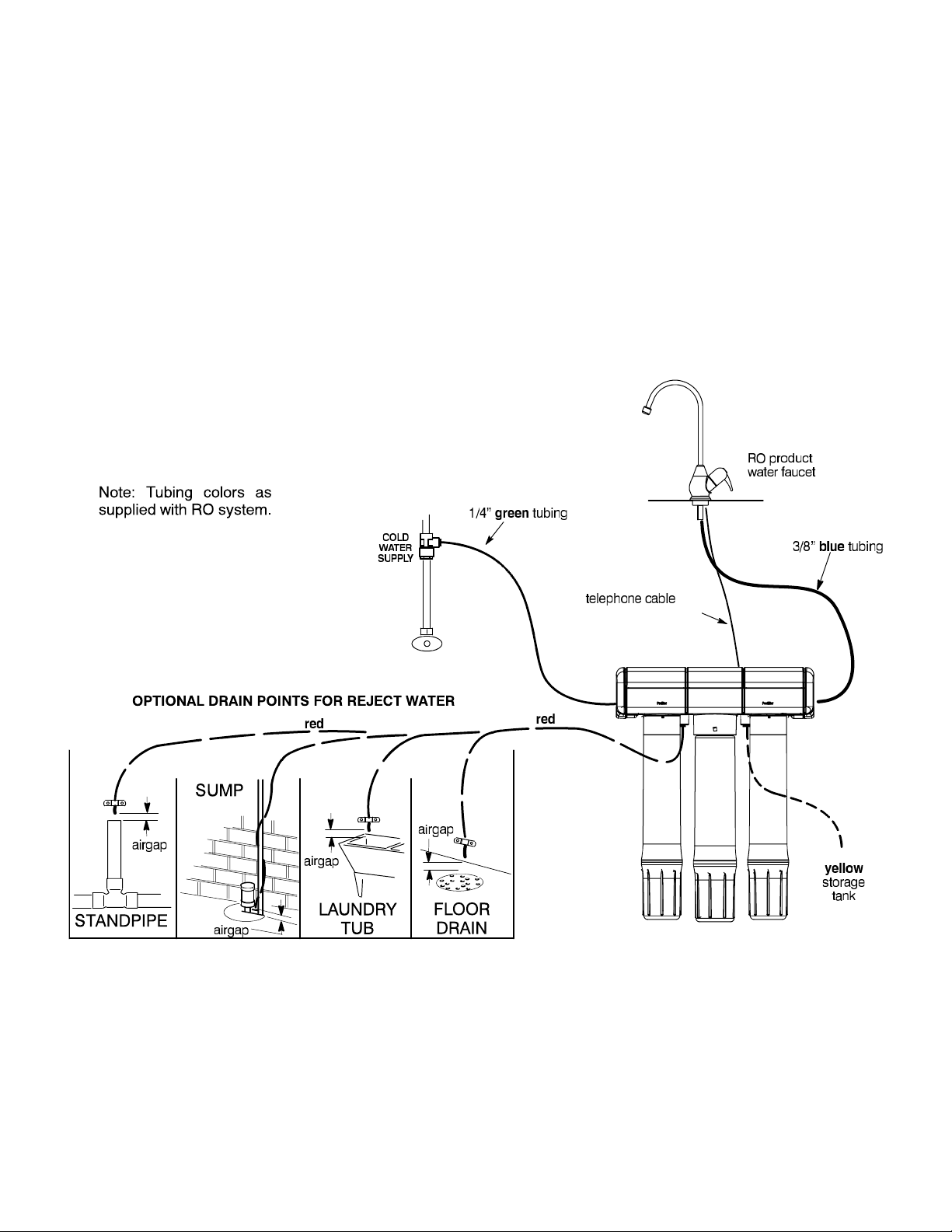
REMOTE LOCATION FOR REVERSE OSMOSIS SYSTEM
Possible remote locations for the RO nearby the kitchen
or bathroom sink include;
(1) a basement area underneath the sink, and
(2) an adjacent room or closet.
Longer lengths of tubing (see parts list) and telephone
cable extension (purchase locally*) may be needed.
FIGURE 24
You can run the drain tubing directly to one of several
suitable open drain points, as shown below, bypassing
the faucet airgap and p-trap drain. This type of drain is
the preferred over the p-trap drain adapter. Check your
local codes. Always be sure to provide an air gap
between the end of the hose and the drain point of
2 pipe diameters or 1 inch, whichever is larger.
*Telephone cable extension must consist of a male connector on one end and a female connector on the other to
keep proper polarity. Polarity may be reversed if a coupler is used and monitor will not work.
(monitored models only)
25
Page 26
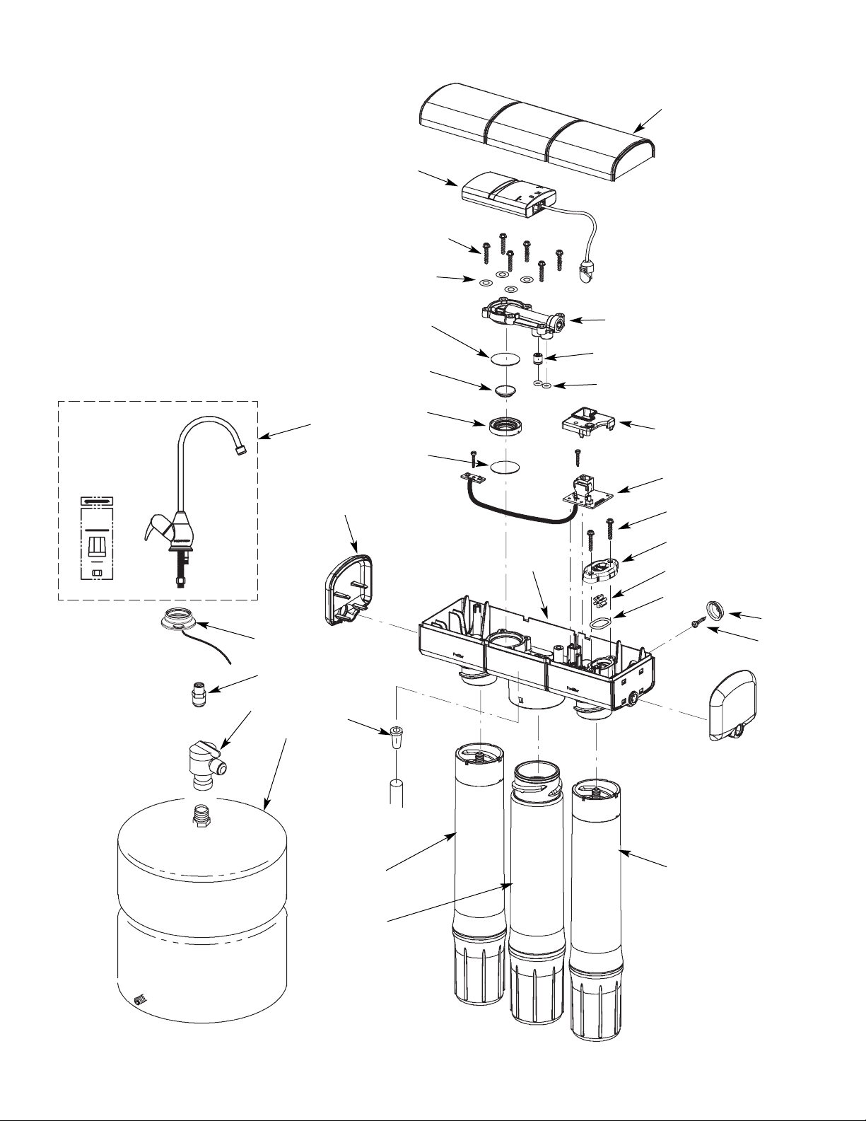
REPAIR PARTS
26
25
24
27
22
21
20
29
22
4
11
30
1
2
5
3
23
19
18
17
16
15
14
13
12
10
9
26
6
7
8
Page 27
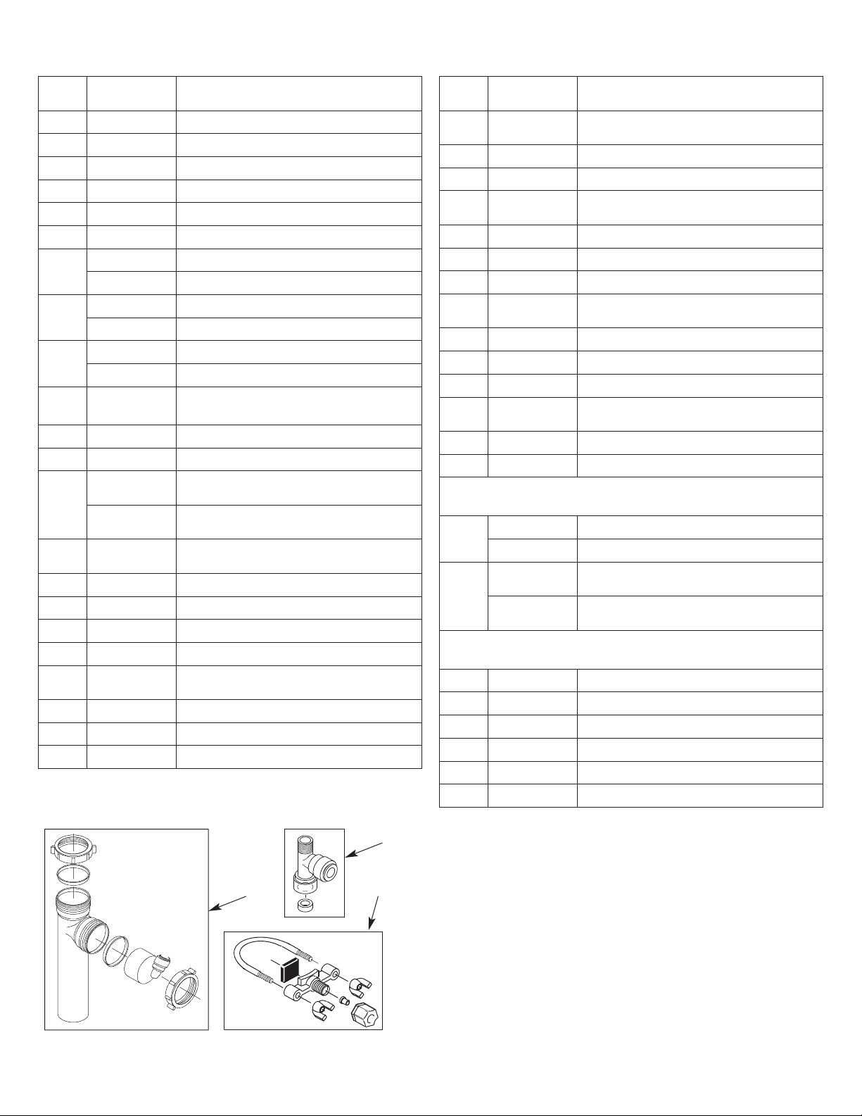
REPAIR PARTS
Key
No.
1 7
2 7
3 7256018 Storage Tank
4 7273379 End Cap (2 req’d)
¢
5 7199486 Flow Control Insert
6
7
8
– 7333129
9
10
11
– 7333200
12
13
14
15
16 7280156
– 7333195 PWA Kit (includes Key No. 17 & decal)
17
¢ á
art No.
P
207920
251034
7095030 Cone Screen
7278913 Pre Filter Cartridge, CTO
7273484
7278905 RO Membrane Cartridge, 50 gpd
7273264
7278913 Post Filter Cartridge, CTO
7273183
á
á
7285376
7285384
á
á
á
á
á
onnector, 7/16-24 x 3/8 Q.C. Tube
C
onnector, 1/4 NPT x 3/8 Q.C. Tube
C
Pre Filter Cartridge, Sediment v
RO Membrane Cartridge, 75 gpd v
Post Filter Cartridge, VOC v
Mounting Hardware Kit
(includes 2 ea. of Key Nos. 9 & 10)
Screw (2 req’d)
Hanger Washer (2 req’d)
Manifold Asm, ERO-375E or HERO-375
(includes Key Nos. 12-25, assembled)
Manifold Assembly, ERO-375
(includes Key Nos. 18-25, assembled)
Paddlewheel Kit, ERO-375E or
HERO-375 (includes. Key Nos. 12-15)
O-Ring, Paddlewheel
Paddlewheel
Cover, Paddlewheel
Screw (2 req’d)
Rep’l Electronic Board (PWA), including screws, ERO-375E or HERO-375
Cover, PWA, ERO-375E or HERO-375
Decal, PWA Cover, ERO-375E or HERO-375
escription
D
Key
No.
– 7333137
18
19
– 7333179
20
21
22
– 7333145
23
24
25
26 7298400
27 7272763 Cover
¢
29
30
31 119-8600084
32 7208489
33 7079791
¢
¢
¢
art No.
P
Check Valve Kit
includes Key No. 19 & 2 of Key No. 18)
(
á
á
á
á
á
á
á
á
7314183 Battery, CR 2032 or eq., ERO-375E only
FAUCET OPTIONS (packaged separately)
7272959 Faucet, Chrome
7277187 Faucet, Brushed Nickel
7261500
7278230
OPTIONAL ACCESSORIES and TUBING
7301203
7161823
7157280
O-Ring, Auto. Shutoff Cover (2 req’d)
Check Assembly
Diaphragm Kit (includes Key Nos. 20, 21
& 2 of Key No. 22)
Spacer Ring
Plunger
Diaphragm (2 req’d)
Automatic Shutoff Kit (includes Key No.
23, 4 of Key No. 24 & 6 of Key No. 25)
Automatic Shutoff Cover Assembly
Washer (4 req’d)
Screw (6 req’d)
Hydrolink®RO Module, with batteries &
cable, HERO-375 only
Electronic Monitor Kit, Chrome,
ERO-375E or HERO-375
Electronic Monitor Kit, Brushed Nickel,
ERO-375E or HERO-375
Water Supply Fitting, 1/4” Q.C. v
Drain Adaptor v
Drain Clamp v
Sanitization Kit v
Tubing, 1/4” x 20’ - white v =
Tubing, 3/8” x 20’ - white v =
escription
D
32
33
31
¢ Not illustrated.
v Not included.
= Tubing lengths for remote installations and for direct
replacement for colored lengths of tubing.
To order parts call your local EcoWater dealer or go to
www.ecowater.com to locate a dealer in your area.
27
 Loading...