

Ecotherm BISOLID Series, Bisolid 30, Bisolid 18, Bisolid 25 Installation, Operation And Maintenance Manual
INSTALLATION, OPERATION AND MAINTENANCE MANUAL
MANUAL
FOR INSTALLATION, OPERATION AND MAINTENANCE OF PELLET
BOILER OF SERIES BISOLID
Pellet boiler Bisolid 20 July 2017 OM-PBBV02/07/2017/EN

INSTALLATION, OPERATION AND MAINTENANCE MANUAL
CONTENT page.
1. IMPORTANT INFORMATION ABOUT THE PELLET BOILER OPERATION .............................. 3
1.1. SAFETY INSTRUCTIONS ............................................................................................................. 3
2. PELLET BOILER BISOLID DESIGNATION .................................................................................. 5
3. DESCRIPTION OF PELLET BOILER FROM SERIES BISOLID .................................................. 6
3.1. MAIN INFORMATION ON THE PELLET BURNER BISOLID GP XX_B HC> .............................. 7
3.2. MAIN INFORMATION ON THE FUEL HOPPER .......................................................................... 9
4. BISOLID PELLET BOILER’S TECHNICAL DATA....................................................................... 11
5. MOUNTING AND INSTALLATION OF PELLET BOILER BISOLID ............................................ 24
5.1. REQUIREMENTS FOR INSTALLATION OF PELLET BOILER BISOLID .................................. 24
5.2. REQUIREMENTS FOR INSTALLATION OF PELLET BURNER BISOLID GP XX_B HC> TO
BOILER BISOLID .................................................................................................................................. 24
5.3. MOUNTING OF HOT WATER PELLET BOILER BISOLID ........................................................ 25
5.3.1. POSITIONING OF THE BOILER ................................................................................................. 25
5.4. METHODIC FOR INSTALLATION OF BOILER .......................................................................... 26
5.4.1. CONNECTION TO A CHIMNEY.................................................................................................. 26
5.4.2. CONNECTING TO THE HEATING INSTALLATION................................................................... 27
5.4.3. INSTALLATION OF PELLET BURNER FROM SERIES BISOLID GP XX_B HC> .................... 27
5.4.4. MOUNTING THE FIRE-CLAY MADE DIRECTING BRICKS ...................................................... 28
5.4.5. POSITIONING/CHECK OF THE ASH CLEANING SECTION COVER ...................................... 29
5.4.6. MOUNTING OF THE COVER PLATE IN FRONT OF THE FLUE GAS OUTLET ...................... 29
5.4.7. MOUNTING OF THE BOILER’S HORIZONTAL COVERS ......................................................... 31
5.4.8. MOUNTING OF THE COVER OVER THE BOILER’S CONVECTION TRACT .......................... 31
5.4.9. MOUNTING OF THE COVER OVER THE BOILER’S COMBUSTION CHAMBER ................... 32
5.4.10. CONNECTING THE PELLET BURNER TO THE BOILER ............................................. 32
5.4.11. MOUNTING OF THE FUEL TRANSPORT AUGER TO THE BURNER ......................... 33
5.4.12. FILLING UP THE FUEL TRANSPORT AUGER .............................................................. 34
5.4.13. CONNECTING OF THE BOILER TO THE MAIN POWER SUPPLY .............................. 34
5.4.14. EXEMPLAR HYDRAULIC DIAGRAM ............................................................................. 34
6. INITIALIZATION OF THE SYSTEM TO OPERATION ................................................................ 36
6.1. MAIN REQUIREMENTS ABOUT THE USED FUEL ................................................................... 36
6.2. INITIALIZATION TO OPERATION OF THE BOILER BISOLID .................................................. 37
6.2.1. GENERAL CONDITIONS ............................................................................................................ 37
6.2.2. POWERING OF THE PELLET BOILER FROM SERIES BISOLID............................................. 37
6.2.3. SWITCHING OF THE SYSTEM ON ........................................................................................... 38
6.2.4. PARAMETERS FOR BOILER OPERATION ADJUSTMENT ..................................................... 38
6.2.5. PARAMETERS FOR ADJUSTMENT OF PELLET BURNER BISOLID GP XX_B HC> ............. 39
6.2.6. NOMINAL OPERATION MODE OF THE BOILER ...................................................................... 39
6.3. ADJUSTMENT OF THE BOILER HEATING OUTPUT ............................................................... 40
6.4. DECREASING THE BOILER HEATING OUTPUT ..................................................................... 40
6.5. INCREASING THE BOILER HEATING OUTPUT ....................................................................... 40
6.6. ADJUSTMENT OF THE COMBUSTION PROCESS .................................................................. 40
6.7. SWITCHING THE BOILER OPERATION OFF ........................................................................... 41
6.8. EMERGENCY BOILER SHUT DOWN ........................................................................................ 41
6.9. SERVICING AND MAINTENANCE OF THE PELLET BOILER BISOLID .................................. 42
6.10. WARRANTY AND WARRANTY CONDITIONS .......................................................................... 44
6.11. ACTIONS AFTER EXPIRY OF THE BOILER LIFE CYCLE ....................................................... 45
7. TROUBLESHOOTING ................................................................................................................. 46
8. WIRING DIAGRAM OF PELLET BOILER BISOLID IN A SYSTEM WITH PELLET BURNER
BISOLID GP XX_B HC> ........................................................................................................................ 49
Pellet boiler Bisolid OM-PBBV02/07/2017/EN
2

INSTALLATION, OPERATION AND MAINTENANCE MANUAL
1. IMPORTANT INFORMATION ABOUT THE PELLET BOILER OPERATION
Dear Bisolid pellet boiler owners,
We would like to congratulate you for your new pellet boiler. By purchasing this quality
product from the manufacturer you have chosen a system that ensures higher comfort level
and optimized fuel consumption in environmentally protecting and natural resource saving
way. Your pellet boiler is manufactured under strict ISO 9001 standards.
On the next pages we have introduced specific information and important advices about the
system operation, its functions and methods of maintenance. Please pay special attention to
this manual. Good knowledge of this document content will give you the pleasure of longterm and trouble-free operation of the pellet boiler.
1.1. SAFETY INSTRUCTIONS
The hot water pellet boiler from series Bisolid and its accessories correspond to all applicable
directions for safety techniques. Your pellet boiler and all of its accessories operate under
variable electricity 230 VAC. Improper electrical installation or repair may endanger user’s life
from electrical shock. Installation works must be performed only by qualified technicians.
This manual is intended for authorized service specialists only. It is important to know that:
Works on the heating installation should be performed only by technicians who had
acquired such rights by law.
Works on the electrical installation should be performed by qualified electricians only.
Initial operation start up including installation visual checks, adjustments and starting
must be performed by the manufacturer authorized personal.
LEGAL PROVISIONS
While operating with the appliance please observe:
Legal provisions for safety techniques.
Legal provisions for environment protection.
Provisions for proper installation.
Applicable provisions of the European community.
SAFETY INSTRUCTIONS
Danger
Please observe these safety instructions in order to prevent the people from
risks and harms, as well as damage to properties and environment.
Safety instructions explanation:
Please pay attention to the following symbols in this manual:
Pellet boiler Bisolid OM-PBBV02/07/2017/EN
3
INSTALLATION, OPERATION AND MAINTENANCE MANUAL
Danger
This symbol warns the user about health risks.
Warning
This symbol warns the user about possible risks and harms to properties and
environment.
Information
This symbol presents text with additional information for the user.
WORKS OR ACTIVITIES FOR SETTING THE APPLIANCE IN PROPER TECHNICAL
WORKING ORDER
Repairs of constructional elements which functions are related to the technical
safety may compromise the safely operation of the installation. Damaged or
faulty elements must be replaced with genuine spare parts provided by the
manufacturer.
After carefully reading of the installation and operation manual, you will
acquire all necessary information about design, controls and safety operation
of the pellet boiler. After unpacking the pellet boiler please check its
completeness and delivered elements. Check whether the pellet boiler size
corresponds to the desired designation.
If any failures or troubles occur the pellet boiler must be led out from operation and removing
of the faults/troubles must be provided by specialized company. For proper functioning, safe
and long-term operation of the pellet boiler, a regular check ups and prophylaxis must be
performed at least once per year. Such technical care guarantees your investment.
Repairs should be performed only with genuine spare parts. In case of faults or troubles
caused by unqualified installation, non-compliance with the requirements or the operation
manual, the manufacturer company is not responsible and does not provide warranty for the
product.
The current manual for operation, installation and maintenance uses notation
of pellet boiler Bisolid includes the model of pellet boilers modification Bisolid
18 (18kW), Bisolid 25 (25kW) и Bisolid 30 (30kW).
Pellet boiler Bisolid OM-PBBV02/07/2017/EN
4

INSTALLATION, OPERATION AND MAINTENANCE MANUAL
Bisolid
2. PELLET BOILER BISOLID DESIGNATION
Type designation of boiler series: Bisolid 18
Example
Boiler trade name
Nominal heating output*, kW
* Similar to other models of hot water boilers Bisolid 25 and Bisolid 30.
The pellet boilers from series Bisolid are designated to utilize wood pellets as the boiler has a
steel made construction. These boilers are used for local heating systems and also for
heating of domestic water. The boiler utilizes wood pellets, as described below, as the
generated heat is accumulated by the heat exchanging surfaces of the boiler body and is
transferred to the heat carrier in the heating system.
The hot water pellet boiler from series Bisolid standard delivery kit includes:
Heat exchanger – 1 unit.
Automated pellet burner with manually mechanically cleaning from series Bisolid GP
xx_B hc> – 1kit.
Ash container (tray) – 1pc.
Boiler’s bottom cover panel (between the second and third pass).
Fire-clay made bricks – 2 pcs.
Flap – 1pc.
Door handle – 1pc.
Cleaning kit (scraper – 1pc, hook – 1pc).
Electrical connector for room thermostat – 1pc.
Power supply cable – 1pc.
Nut and washer M10 – 2 pcs.
Manual for installation, operation and maintenance of the boiler – 1pc.
The pellet boiler from series Bisolid is designated to utilize wood pellets with diameter Ø 68mm, from class A1 according to standard EN ISO 17225-2:2014.
Boiler’s advantages:
Compact and simple steel structure that allows dynamic operation, easy installation
and operation - plug & play.
Compact control, interface panel and exported in the back end of the boiler
connectors.
Ability to work with a room thermostat (weekly programmable).
Meets the most stringent European requirements and standards (EN 303-5:2012).
High efficiency and low emissions.
Ability to providing domestic hot water (DHW).
Minimum operating costs.
The boilers are available in two versions for left or right side burner adjustment.
18
Pellet boiler Bisolid OM-PBBV02/07/2017/EN
5
INSTALLATION, OPERATION AND MAINTENANCE MANUAL
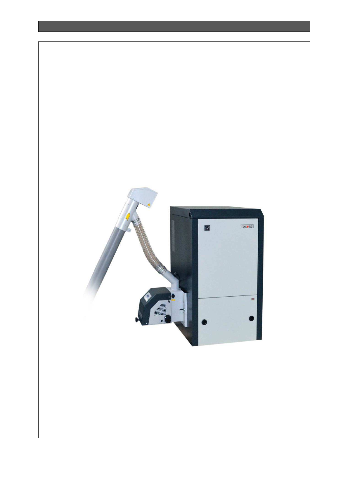
3. DESCRIPTION OF PELLET BOILER FROM SERIES BISOLID
The steel made hot water pellet boiler from series Bisolid is designated for heating of local
installations with natural or forced water circulation performed with or without circulations
pump. The heat exchanger unit is module of the system designated for automatic utilization
of pellets and for heating of the circulations water. The cleaning of the ash from the burning
process can be performed manually through the combustion chamber’s lower front door, by
taking out the ash-tray and gathering its content in proper for the purpose containers. The
combustion process organization and the heat exchanging with the boiler body internal
surfaces ensures high efficiency. The operation of the system: hot water pellet boiler from
series Bisolid and automated pellet burner with manually cleaning from series Bisolid GP
xx_B hc> depend on the chimney draught. The chimney draught depends on the chimney
condition and on the flue gas temperature.
The hot water boiler’s Bisolid heat exchanger construction complies with the resistance
requirements for such type of appliances: EN 303-5:2012 - "Heating boilers. Part 5: Heating
boilers for solid fuels, manually and automatically stoked, nominal heat output of up to 500
kW. Terminology, requirements, testing and marking.
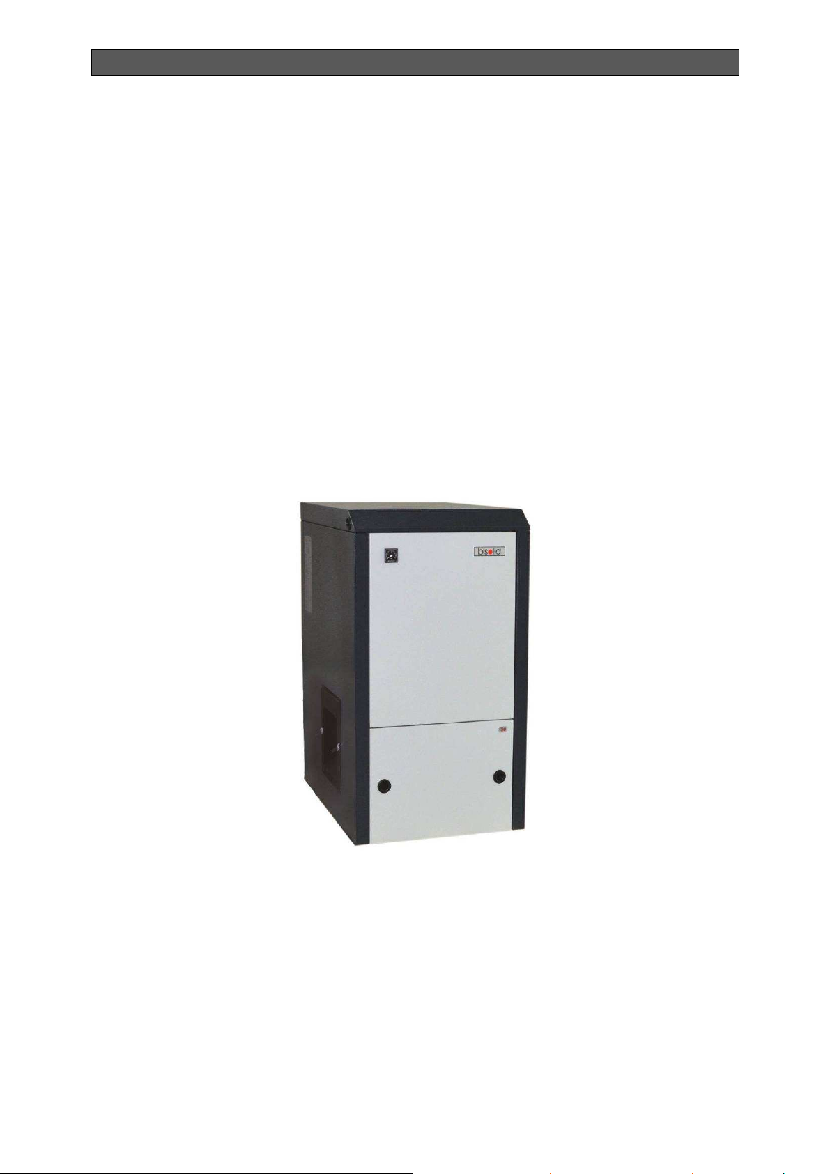
Figure 3.1. External view of steel made hot water pellet boiler from series Bisolid.
The boiler consists of the following components/modules:
The main module of the hot water boiler is the boiler body (heat exchanger), as the
automated burner from series Bisolid GP xx_B hc> is mounted on its side. The heat
exchanger is offered in two versions: so called “left” and “right” mounting. The
automated pellet burner with manually mechanically cleaning can be mounted only on
the left or only on the right side of the boiler body.
The heat exchanger unit construction is made of steel plates. The combustion
chamber is designed in the front lower part of the heat exchanger, as the ash
container is below it. The heat exchanger is with compact size related to the achieved
heating output, because it has three pass design, which provides optimal heat
exchanging and high efficiency.
Pellet boiler Bisolid OM-PBBV02/07/2017/EN
6

INSTALLATION, OPERATION AND MAINTENANCE MANUAL
Fire clay made components mounted in the combustion chamber, which ensure
optimal burning process and complete fuel combustion.
The ash-tray is positioned at the bottom of the combustion chamber. The ash
residues are gathered in it providing easy cleaning.
The water inlet and outlet muffs are positioned at the boiler’s back side and are inner
threaded with size G1½”, as through them the appliance can be connected to the
heating system.
The flue outlet (with external diameter Φ149 mm) is positioned centrally in the top
rear side of the boiler and serves for extraction of the flue gasses to the chimney.
The steel made heat exchanger, its cover and doors are isolated with mineral wool,
which limits the heating losses to the local environment.
Manometer, positioned on the boiler body’s front panel, indicates the circulations
water pressure in the heat exchanger.
External decoration side cover panels made of steel plates and painted with high
quality color coating materials.
3.1. MAIN INFORMATION ON THE PELLET BURNER BISOLID GP XX_B HC>
The pellet burner with manually cleaning from series Bisolid GP xx_B hc> is mounted
horizontally and laterally ("left" or "right" installation) of the hot water boiler from series Bisolid
and it is a separate (standalone) module.
The kit of the pellet burner with manually cleaning from series Bisolid GP xx_B includes:
Main module – 1pc.
Fuel transport auger – 1 pc.
Flexible pipe – 1 pc. with brackets – 2 pcs.
Manual for installation, maintenance and operation of pellet burner from series Bisolid
GP xx_B hc> – 1 pc.
The main module of automated pellet burner with manually cleaning from series Bisolid GP
xx_B hc> consists of the following components:
Combustion chamber, that provides conditions for optimal burning process and is
made of high quality fire-proof steel.
Fire-grate of the combustion chamber, that can be easily removed and provides
availability for easy cleaning of the ash.
Air distribution tract, that provides equal firing air distribution and cooling of the
burner’s components.
Electrical heating element, used for initial fuel firing and positioned under the
combustion chamber’s fire-grate.
Fresh (firing) air fan, equipped with sensor for determining the rotation velocity and
providing availability for adjustment.
Photo-sensor for monitoring of the burning process, positioned sideways for easier
cleaning.
Emergency temperature sensor for prevention of the so called “back fire” in the
pellets inlet pipe.
Control module, for monitoring and controlling of the burner operation.
Fuel transport auger connector, used for powering the auger.
Interface panel, equipped with display and keyboard for easy adjustment.
Linkages handle for manually mechanical cleaning of the grate in the combustion
chamber of the burner.
The pellet burner kit includes electrical powered external auger used for transportation of the
fuel from the hopper to the burner. The auger consists of compact size motor-gear equipped
Pellet boiler Bisolid OM-PBBV02/07/2017/EN
7
INSTALLATION, OPERATION AND MAINTENANCE MANUAL
with integrated overheating protection, pipe in which the fuel is transported to the flexible
pipe drop zone.
The flexible pipe made of special transparent thermo-resistant inflammable material (it melts
but does not separate toxic substances) that connects the auger and the burner’s main
module.
The main advantages of the pellet burner from series Bisolid GP xx_B hc> are:
The pellet burner’s are fully automated – ignition, flame control, combustion chamber
blowing. It is also equipped with intuitive LCD display for easy operation.
Automatic adjustment of fresh air and fuel feed rates according to the selected
operating temperature, which feature provides high efficiency of the appliance at
minimum fuel consumption.
Automatic modulation of the burning process decreasing the number of stops and
ignitions, respectively fuel and electricity consumption.
Manually mechanical cleaning of the fire-grate, through leverage without opening the
boiler and without interruption of the operation.
Circulations pump control according to heat carrier (water) temperature.
Quiet operation and low electric power consumption.
Protection from back-fire and from heat carrier (water) freezing.
Circulations pump protection against blocking.
Possibility for control of extractor (flue gas) fan.
Possibility for operation with room thermostat and week programmer.
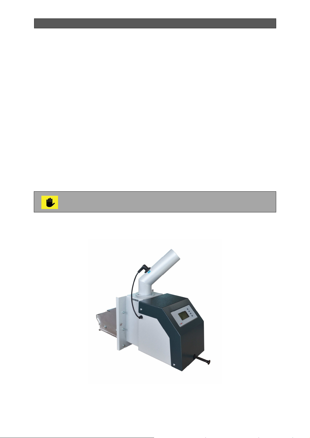
The actual and detailed information on the construction and technical data of
the pellet burner with manually cleaning from series Bisolid GP xx_B hc> is
given in its manual for operation.
Figure 3.2. External view of automated pellet burner with manually cleaning from series
Bisolid GP xx_B hc>.
Pellet boiler Bisolid OM-PBBV02/07/2017/EN
8
INSTALLATION, OPERATION AND MAINTENANCE MANUAL
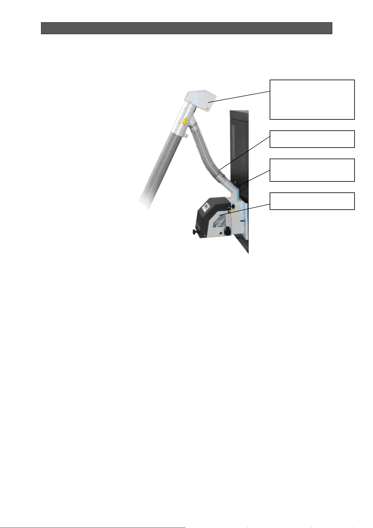
Figure 3.3. Arrangement of the main modules of the pellet burner
(side view).
External auger for fuel
transport from hopper to
the main burner’s
module
Flexible pipe
Pipe for pellets feeding
Main module
3.2. MAIN INFORMATION ON THE FUEL HOPPER
The pellet hopper is the “reservoir” of the pellet kit that provides conditions for compact
storing of the fuel, needed for long-term operation of the system and optimal conditions for
operation of the burner’s transport auger. In case the hopper is build/constructed at the
customer’s site then its construction must provide free (gravity) fuel flow to the auger’s intake
zone, easy refueling, cleaning and enough capacity for longer operation of the system.
The manufacture company produces sectional (assembled) pellets hoppers, made of
galvanized steel plates, with capacity: 250, 450 и 650 kg.
Pellet boiler Bisolid OM-PBBV02/07/2017/EN
9

INSTALLATION, OPERATION AND MAINTENANCE MANUAL
Figure 3.4. Sectional (assembled) sheet metal pellets hopper with 250kg capacity.
Figure 3.5. Sheet metal pellets hopper with capacity of 300 l.
Pellet boiler Bisolid OM-PBBV02/07/2017/EN
10

INSTALLATION, OPERATION AND MAINTENANCE MANUAL
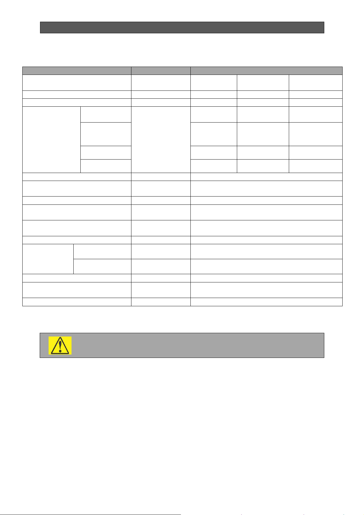
4. BISOLID PELLET BOILER’S TECHNICAL DATA
The technical heating data for hot water pellet boiler from series Bisolid are presented in
Table 4.1.
Table 4.1. Technical heating data for hot water pellet boiler from series Bisolid.
PARAMETER DIMENSION VALUE
Pellet boiler model
Nominal heat output kW 18 25 30
Heating output adjustment
range
Used fuel Wood pellets
Suitable wood pellets class
according to standard
EN ISO 17225-2:2014
-
kW 7.5 - 18 7.5 – 25 9 - 30
- A1
Bisolid 18
Bisolid 25 Bisolid 30
Required air quantity to
achieve effective burning
process
Flue gas mass flow rate g/s 9.4 15.6 19.8
Energy efficiency class
according to regulation
(ЕU) 2015/1187
Efficiency at nominal operation
mode
Excess air ratio coefficient
Flue gas temperature at
nominal operation mode
Residues from the burning
process
The technical data for hot water pellet boiler from series Bisolid are presented in Table 4.2.
kg/h 27 – 30 45 – 50 57 - 64
m3/h 24 – 27 39 – 44 50 - 56
-
℅ 92.4 91.5 91.0
λ 1.5 – 1.7
ºC 160 170 180
Ash
The quantity depends on the fuel’s ash
content
Pellet boiler Bisolid OM-PBBV02/07/2017/EN
11
INSTALLATION, OPERATION AND MAINTENANCE MANUAL
-
Table 4.2. Technical data for hot water pellet boiler from series Bisolid.
PARAMETER DIMENSION VALUE
Hot water pellet boiler model
Boiler weight kg 192 212 222
Boiler water volume dm³ 44 50 60
Overall
dimensions of
the system:
W х D х H
W1- Length of
boiler body
W – Length
with pellet
burner
D - Depth
-
mm
Bisolid 18
580 580 580
954 954 954
770 770 770
Bisolid 25 Bisolid 30
H -Height
Boiler class - 5
Operation water overpressure in
the boiler
Boiler test overpressure
Recommended operation water
temperature in the boiler
Minimum boiler inlet water
temperature
Chimney draught *
Connection
pipes
Power supply voltage - L1, N, PE, 50Hz; 230VАС;
Electrical consumption (with
ignition)
System electrical protection
* If the chimney draught operation parameters are lower than the above presented values it
is necessary to install flue gas extraction fan.
The technical parameters of hot water solid fuel boilers series Bisolid according to the
delegated Regulation (EU) 2015/1187 are presented in Table 4.3.
Inlet/outlet water
Flue outlet
The selection, installation and connection to the flue gas extraction fan have to
be made by the technically trained and qualified person.
bar 2.5
bar 4
ºC 80
ºC 60
Pa 12-15*
G 1½”
mm 149
W
885 965 1044
+1100
<100
IP20
Pellet boiler Bisolid OM-PBBV02/07/2017/EN
12

INSTALLATION, OPERATION AND MAINTENANCE MANUAL
no
no
no
no
no
no
no
no
no
no
no
no
no
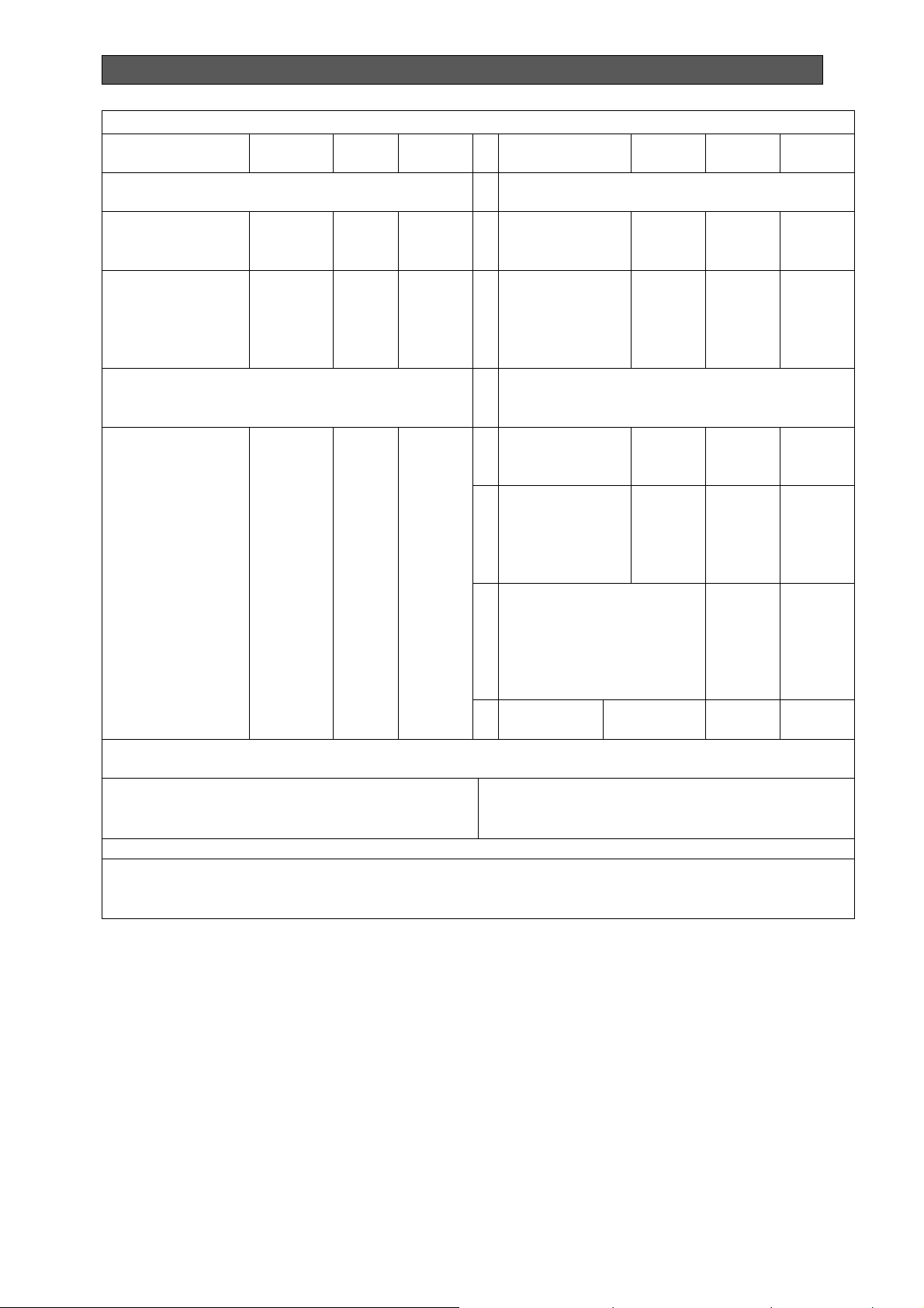
Characteristics when operating with the preferred fuel:
Table 4.3 Technical parameters of hot water solid fuel boilers series Bisolid according to the
delegated Regulation (EU) 2015/1187.
Model identifier: Hot water pellet boiler Bisolid 18.
Stoking mode: Automatic: it is recommended that the boiler be operated with a hot water storag e
tank of a volume of at least 360 litre (**)
Condensing boiler: no
Solid fuel cogeneration boiler: no
Combination boiler: no
Fuel
Log wood, moisture content ≤ 25 % no no
Chipped wood, moisture content 15-35 % no
Chipped wood, moisture content > 35 % no
Compressed wood in the form of pellets or briquettes yes no
Sawdust, moisture content ≤ 50 % no
Other woody biomass no
Non-woody biomass no
Bituminous coal no
Preferred
fuel (only one):
Other suitable
fuel(s):
Brown coal (including briquettes) no
Coke no
Anthracite no
Blended fossil fuel briquettes no
Other fossil fuel no
Blended biomass (30-70 %) and fossil fuel briquettes no
Other blend of biomass and fossil fuel no
Seasonal space heating energy efficiency ƞs [%]: 87
Pellet boiler Bisolid OM-PBBV02/07/2017/EN
13
INSTALLATION, OPERATION AND MAINTENANCE MANUAL
Auxiliary electricity consumption
Energy efficiency index EEI: А+
Item Symbol Value Unit Item Symbol Value Unit
Useful heat output Useful efficiecny
At rated heat
Pn (***) 18 kW
output
At [30 %/50%] of
Рр 11 kW
rated heat
output, if
applicable
For solid fuel cogeneration boilers: Electrical
efficiency
At rated heat
output
Ƞ
el,n
-
%
At rated heat
output
At [30 %/50%]
of rated heat
output, if
applicable
At rated heat
output
At [30 %/50%]
of rated heat
output, if
applicable
Of incorporated
secondary emission
abatement equipment,
if applicable
ƞn 92,4 %
ƞp 92,6 %
el
0,156 kW
max
el
0,134 kW
min
- kW
PSB 0,0048 kW
Contact details
In standby
mode
Ekoterm Proekt EAD / ZMM Haskovo AD
6300, Haskovo
67 Saedinenie Blvd.
(*) Tank volume = 45 × Pr × (1 – 2,7/Pr) or 300 litres whichever is higher, with Pr indicated in kW
(**) Tank volume = 20 × Pr with Pr indicated in kW
(***) For the preferred fuel Pn equals Pr
Pellet boiler Bisolid OM-PBBV02/07/2017/EN
14

INSTALLATION, OPERATION AND MAINTENANCE MANUAL
Characteristics when operating with the preferred fuel:
Model identifier: Hot water pellet boiler Bisolid 25.
Stoking mode: Automatic: it is recommended that the boiler be operated with a hot water storag e
tank of a volume of at least 500 litre (**)
Condensing boiler: no
Solid fuel cogeneration boiler: no
Combination boiler: no
Fuel
Log wood, moisture content ≤ 25 % no no
Chipped wood, moisture content 15-35 % no no
Chipped wood, moisture content > 35 % no no
Compressed wood in the form of pellets or briquettes yes no
Sawdust, moisture content ≤ 50 % no no
Other woody biomass no no
Non-woody biomass no no
Bituminous coal no no
Preferred
fuel (only one):
Other suitable
fuel(s):
Brown coal (including briquettes) no no
Coke no no
Anthracite no no
Blended fossil fuel briquettes no no
Other fossil fuel no no
Blended biomass (30-70 %) and fossil fuel briquettes no no
Other blend of biomass and fossil fuel no no
Seasonal space heating energy efficiency ƞs [%]: 89
Energy efficiency index EEI: А+
Pellet boiler Bisolid OM-PBBV02/07/2017/EN
15

INSTALLATION, OPERATION AND MAINTENANCE MANUAL
Auxiliary electricity consumption
Item Symbol Value Unit Item Symbol Value Unit
Useful heat output Useful efficiecny
At rated heat
Pn (***) 25 kW
output
At [30 %/50%] of
Рр 18 kW
rated heat
output, if
applicable
For solid fuel cogeneration boilers: Electrical
efficiency
At rated heat
output
Ƞ
el,n
-
%
At rated heat
output
At [30 %/50%]
of rated heat
output, if
applicable
At rated heat
output
At [30 %/50%]
of rated heat
output, if
applicable
Of incorporated
secondary emission
abatement equipment,
if applicable
ƞn 93,9 %
ƞp 94,1 %
el
0,156 kW
max
el
0,134 kW
min
- kW
PSB 0,0048 kW
Contact details
In standby
mode
Ekoterm Proekt EAD / ZMM Haskovo AD
6300, Haskovo
67 Saedinenie Blvd.
(*) Tank volume = 45 × Pr × (1 – 2,7/Pr) or 300 litres whichever is higher, with Pr indicated in kW
(**) Tank volume = 20 × Pr with Pr indicated in kW
(***) For the preferred fuel Pn equals Pr
Pellet boiler Bisolid OM-PBBV02/07/2017/EN
16
 Loading...