

Page 1

Instruction Manual
MP40w
Protecting your VorTech
Protect the pump from water
The VorTech’s motor housing and
driver are NOT WATERPROOF. Any
water allowed into these components
can damage them enough to require
replacement. This kind of damage is
NOT covered in the VorTech’s warranty.
Protect these components from splashes
of any kind.
Maintenance
Wear of the drive shaft
The VorTech pump features a wear
component in the form of the drive shaft.
This part is designed with a special
engineering grade plastic which extends
the part’s lifetime. The plastic drive
shaft can be expected to last for years,
depending on the speed, frequency, and
alignment of the pump.
The wet magnet and drive shaft should
be observed periodically to monitor
wear. If the magnet begins to how signs
of rapid oxidation in the form of bubbles
on the magnet surface, they may need
to be replaced. Replacements can be
purchased directly from EcoTech Marine.
Cleaning your VorTech
The VorTech may need thorough cleaning
of the components periodically to
keep it running optimally. This can be
accomplished by disassembling the wet
half of the pump and gently brushing
the components with a soft brush under
running water. Soaking these par ts in
a mild acid solution such as vinegar
may be necessary if there is an extreme
amount of calcium buildup. Do not use
strong acids as this may damage the
components.
Troubleshooting
Break-in
The VorTech pump is engineered to adapt
to its aqueous environment. During the first
week of use, your pump may run noisier or
stall. The noise should quiet dramatically over
night and any stall conditions can safely be
reset by manually cycling the power to your
pump.
Driver Error Codes
Over Temperature Condition
In the event of a motor overheating, the
pump will automatically shut down for a
period to allow for cooling. Once the motor
has cooled, the driver will automatically
restart and resume normal operation. You
may experience an overheating error from a
misalignment.
Stall Condition
In the event of a motor stall, the pump may
have stopped for a few possible reasons. You
should first check that there is not something
blocking the propeller from spinning. Next,
check to make sure the magnets are not
rubbing on either the pin spacer or the frame
cover.
Miscellaneous Error
This error could be attributed to a
communication error between pumps or an
unidentified error in the wave driver.
FCC Warnings:
Operation is subject to the following two
conditions: (1) this device may not cause
interference, and (2) this device must accept
any interference including interference that
may cause undesired operation of the device.
Changes or modifications not expressly
approved by EcoTech Marine could void
the user’s authority to operate the VorTech
Wireless Wave Driver.
Customer Support
service@ecotechmarine.com
(610) 954-8480
OR visit our forum at www.ReefCentral.com
Sales inquiries please contact:
sales@ecotechmarine.com
(800) 785-0338
ErrorCodes:
Stall
Condition
OverTemp
Condition
MiscError
Normal Oxidized
Page 2
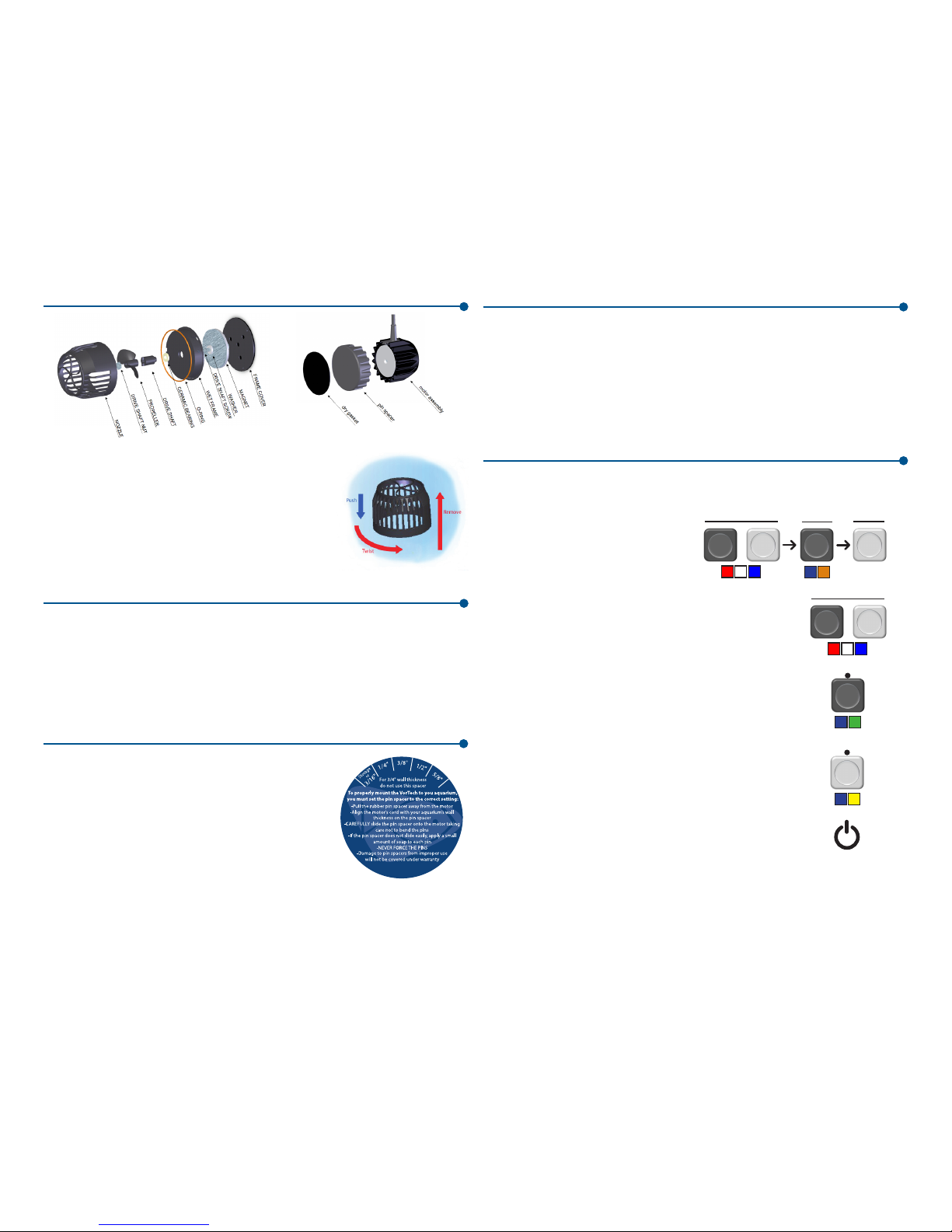
To remove the nozzle from the wet-frame, remove the entire
wet-half of the pump from the aquarium and place it on a nonmetallic surface. Gently but firmly press down on the nozzle
with your palm and twist counter clockwise. The nozzle should
become free of the wet-frame. It may then be cleaned of any
obstructions
Specifications and Operating Parameters
Flow: 200-3,000 gallons/hour, Power: 12-23 watts,
Maximum Motor Temp: 50-60 degrees C
Aquarium Wall Thickness: 3/16” to 3/4”
Your VorTech propeller pump
Before you start
Preparation
Once you have chosen the location where you wish to install your VorTech pump, clean •
away any algae, calcified or otherwise, using a razor blade.
Notes on placement
The VorTech creates over 3,000 gallons per hour of low velocity flow within your aquarium.
Take care to place the VorTech in a suitable location where corals are not directly in the
line of flow. Place the pump sufficiently high enough above a fine sand bed so that sand is
not blown around by the output or undertow created by the VorTech.
Adjust the pin spacer
The VorTech pump is designed to operate with a constant
gap between both halves of the device. The pin spacer is
used to ensure the proper spacing for various aquarium wall
thicknesses.
Make sure to measure your aquarium’s glass thickness us-•
ing a ruler or contact the aquarium manufacturer in order
to determine the exact thickness.
To adjust for the proper aquarium thickness, pull the pin •
spacer from the motor housing. Then align the VorTech’s
power cord emerging from the motor with your aquarium’s wall thickness to achieve the proper offset from your
aquarium.
Note: 5/8” and 3/4” thick aquariums do not use the pin spacer at all.
IMPORTANT: When adjusting the pin spacer, be sure not to bend the pins as they are
inserted into the holes within the heat sink as this may permanently damage your
VorTech. Bent pins WILL NOT be covered under warranty.
Sync Mode
When a slave pump is entered into sync mode, it will replicate exactly what the master
pump is doing. This function can be used with a master pump that is currently in any
general mode of operation.
Anti-Sync Mode
When a slave pump is entered into Anti-Sync Mode, it will inversely replicate the master
pump. For example, when the master pump is at high speed, the slave pump will be at low
speed. This function can be used with a master pump that is currently in lagoon, reefcrest, or pulse modes. In constant speed mode, the anti-sync pumps will operate at the
same speed as the master pump.
Slave Modes
Step 1: Clear Driver Memory
The internal memory of each unit must be
cleared before setting up a group.
Programming Multiple Pumps
A pump group consists of one master pump and at least one slave pump. There can only
be one master pump per group which can include an unlimited number of slave pumps. It
is possible to have up to eight groups in one area each with a unique master pump.
Step 2: Enter Configuration Mode
All pumps in a group must then be set into configuration mode
before the assignment of slave or master status. This configuration
must be performed with the drivers in close proximity to ensure
proper assignment. The drivers will blink red, white and blue in this
mode.
Step 3: Assign the Master
Set the master pump by pressing the mode button. The LED will
then blink blue and green.
+
Step 4: Assign the Slaves
Set all the slave pumps by pressing the set button on each driver.
The LED will then blink blue and yellow.
Step 5: Cycle the Power
Pull the power cord from the driver box to reset each pump. They
will restart in their respective slave or master modes. Alternatively,
hold mode on any one pump to rest them all.
Cycle
Power
Step 6: Program Subsequent Groups
Now that the first group is programmed, repeat steps 1-5 on then next group of pumps if
so desired.
NOTE: The subsequent pump groups must be programmed near the original group. For
example, if running two different groups in separate areas of your house, the second
group must be programmed near the first group to ensure proper communication.
Pump
Resets
+
hold
hold
hold
hold
tap
tap
Page 3

Your VorTech Wireless Wave Driver
General Operational Modes
Constant Speed Mode
When a pump is in constant speed mode, the dial is used to set the operational speed. If
this pump is a master, the associated slave pumps will replicate the master.
Reef-Crest Random Mode
When a pump is in Reef-Crest Random Mode, the dial is used to set the maximum
operational speed, and the driver will automatically randomize the pumps output to
simulate a high energy reef-crest environment. If this pump is a master pump, the
associated slave pumps will replicate the master in sync or anti-sync modes.
Lagoonal Random Mode
When a pump is in Lagoonal Random Mode, the dial is used to set the maximum
operational speed, and the driver will automatically randomize the pumps output to
simulate a low energy lagoonal reef environment. If this pump is a master, the associated
slave pumps will replicate the master in sync or anti-sync modes.
Pulse Mode
When a pump is first entered into Pulse Mode, you must set the maximum pump speed
by adjusting the dial. When the desired speed is achieved, press the Set button to lock
this speed. The LED will now begin to blink. This blinking LED represents the pulsing
frequency. Now adjust the dial to make the pump pulse faster or slower.
Feed Mode
To enter Feed Mode, press and hold the mode button for three seconds. The LED will
now blink white indicating that the pumps are in feed mode. Regardless of your system’s
master/slave pump configuration, all pumps will enter feed mode when that mode is
selected on any one pump. The pumps will spin very slowly for ten minutes and then
resume their prior operating conditions.
Battery Backup Mode
When a battery backup accessory is added to the VorTech pump the pump will
automatically switch to Battery Backup mode during a power outage. The pumps will run
at the minimum speed to maximize their run time during this critical period.
The wireless wave driver has seven different modes of
operation, and can be assigned to a master or a slave
pump configuration. If you assign a pump to be a
master, it will communicate wirelessly with the slave
pumps.
There are two buttons and one dial on your driver.
Use the mode button to switch between the different
modes of operation. The dial and set button will be
used to adjust the speeds and frequencies of the
different modes.
The VorTech utilizes very powerful magnets and can cause severe personal injury.•
NEVER connect the two halves of this device without a proper spacer in-between.•
NEVER place either half of this device near magnetically attractive surfaces or sensitive •
electronics.
The motor and driver can become HOT. Be cautious around these surfaces.•
Never run the pump dry as the heat buildup may cause damage to your components.•
Warnings
Attach the VorTech
Attach the motor assembly
Apply the rubber gasket at the chosen location for the VorTech •
pump, on the outside of your aquarium.
Apply the cord mounting tab approximately 2” above this loca-•
tion. Make sure the glass is clean and free of any grease or
dirt prior to applying this tab.
Place the VorTech motor, with or without the pin spacer at-•
tached, upon the black gasket, and secure the cord to the
mounting tab using one of the provided wire-ties.
The cord must be positioned pointing upwards so that if the •
VorTech were to fall off the aquarium, it does not swing and
damage your aquarium. When operating, make sure the gasket
is properly recessed within the pin spacer.
Attach the propeller housing
Apply the wet gasket/cover to the rear of the propeller housing. •
Place this into the aquarium, making sure to allow ALL air to •
escape from the propeller housing.
Carefully connect both halves of the pump together and visually •
align both halves of the pump.
Align the VorTech
Turn the speed up to the maximum speed by using the •
speed control knob on the driver.
Plug the power supply into the driver. If vibration or •
noise is detected, carefully adjust the propeller housing by moving it VERY slightly left, right, up or down,
until the noise/vibration is eliminated or minimized as
much as possible.
After alignment has been ensured, turn the speed •
control knob to achieve the desired flow rate within
your aquarium.
IMPORTANT: If the VorTech is not properly aligned, a strong vibration will be heard. If the
alignment is not corrected, this can cause increased electrical consumption, excessive wear
on the components, excessive heat and excessive noise.
Protect the Pump From falling
Due to the nature of the magnetically coupled design, it is possible for the VorTech to
become dislodged from the aquarium glass and fall to the ground. The cord should be
positioned vertically above the pump with the mounting tab directly above the motor to
ensure that the motor does not move in the event of a decoupling of the magnets.
The provided cord-mounting tab MUST be used to prevent damage to the motor or the •
surrounding environment.
The motor will shut down automatically if either half of the pump is removed.•
SlavePumpModes:
Sync AntiͲSync
Mode
Set
Constant
Speed
Lagoon
Random
ReefͲCrest
Random
Pulse
speed
SinglePumpModeorMasterModes:
OperationalModes
Holdtoenter
andexit
FeedMode:
Pulse
frequency
Battery
Backup
Blinking
White
 Loading...