

ECOSTAR ECO 50 NG, ECO 55 NG, ECO 60 NG, ECO 65 NG, ECO 70 NG Installation, Operating And Maintenance Manual
Page 1
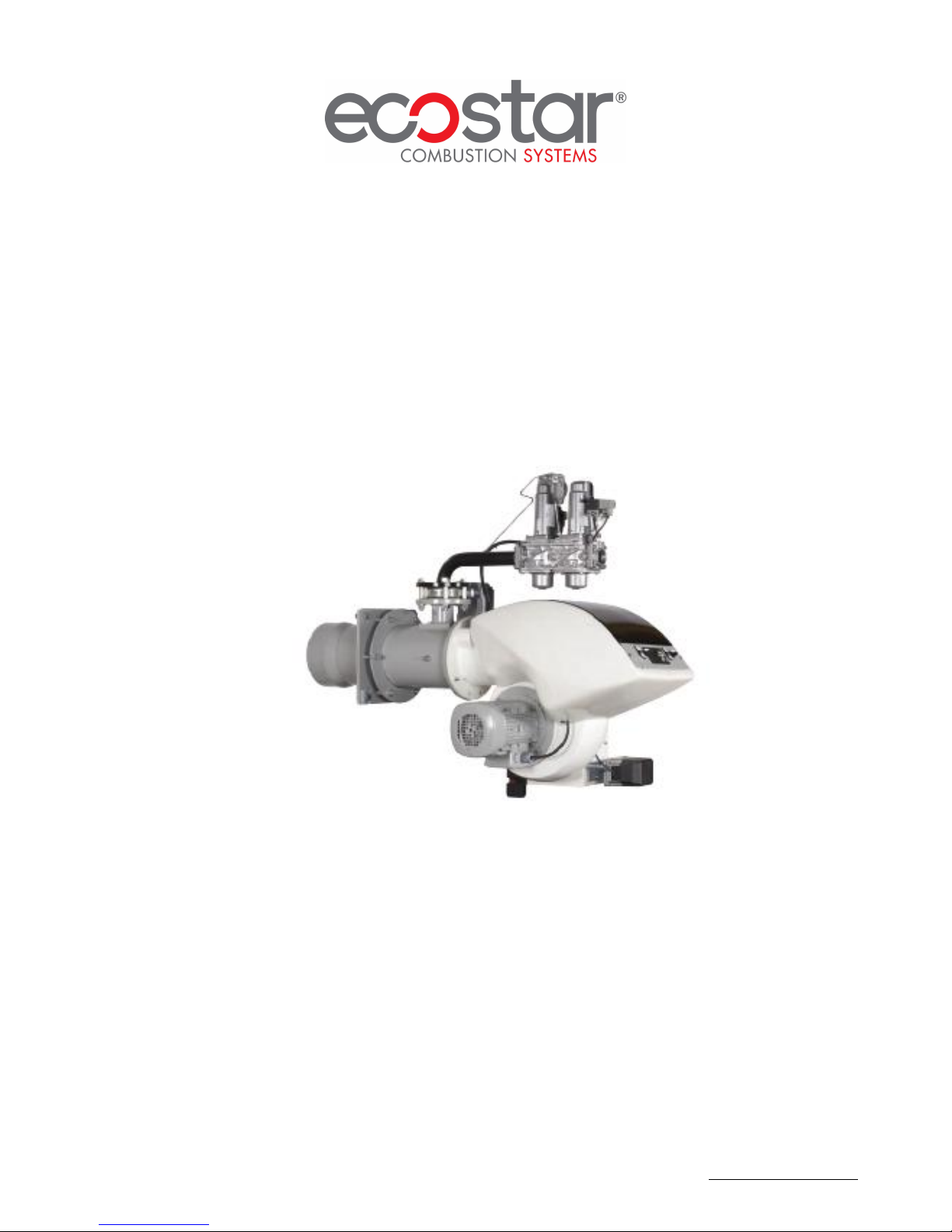
MONOBLOCK NG SERIES GAS BURNERS
INSTALLATION, OPERATING AND MAINTENANCE
MANUAL
MODULATING OPERATION
ECO 50 NG
ECO 55 NG
ECO 60 NG
ECO 65 NG
ECO 70 NG
www.ecostar.com.tr
Page 2

DEAR USER,
ECOSTAR ECO 50 NG, ECO 55 NG, ECO 60 NG, ECO 65 NG, ECO 70 NG
Series Gas burners are prepared and manufactured according to the latest technical
developments and safety rules. It is easy to use for our customers.
We recommend that you read this manual and safety warnings thoroughly before the
use of the device in order to ensure safe, cost effective and environmental-friendly use.
If you encounter any issue that is not explained clearly in this manual or you could
not understand, please contact with our service department.
We thank you for choosing ECOSTAR brand.
This Operating Manual is an integral part of the burner and must be maintained in a
plastic dossier and hung at a clearly visible place in the burner room.
TERMO ISI SİSTEMLERİ SAN.VE TİC.A.Ş.
Kartal Monumento Plaza
Kartal/İSTANBUL/TÜRKİYE
www.ecostar.com.tr
13.06.2017 Rev. 01 1
Esentepe Mah.Milangaz Cad. No:75 K:3
Tel: +90 216 442 93 00
Fax: +90 216 370 45 03
e-mail:[email protected]
Page 3

CONTENTS
WARNINGS ............................................................................................................................................... 3
Warning Symbols and Descriptions ........................................................................................................ 3
General Safety Rules .............................................................................................................................. 4
TERMS OF WARRANTY ......................................................................................................................... 6
Out of Warranty Conditions ................................................................................................................... 6
BURNER’S GENERAL FEATURES ........................................................................................................ 7
Purpose of Use and Work Limits of Burners .......................................................................................... 7
Code Key ................................................................................................................................................ 7
TECHNICAL DATA .................................................................................................................................. 8
Capacity Table ........................................................................................................................................ 8
Back Pressure-Capacity Diagrams .......................................................................................................... 9
Burner Dimensions ............................................................................................................................... 10
Flame Length and Diameter .................................................................................................................. 11
Noise Level ........................................................................................................................................... 11
BURNER HANDLING INFORMATION ................................................................................................ 11
INSTALLATION ..................................................................................................................................... 12
Burner Installation Picture .................................................................................................................... 12
COMMISSIONING .................................................................................................................................. 13
Before Commissioning ......................................................................................................................... 13
General Controls ................................................................................................................................... 13
Combustion Adjustment ....................................................................................................................... 14
Gas Adjustment .................................................................................................................................... 14
VGD 40… Series Gas Valve ................................................................................................................ 14
Air pressure switch adjustment ............................................................................................................. 15
BT 300 ...................................................................................................................................................... 15
Operating Control and Displays ............................................................................................................ 16
Leakage Test for Main Gas Valves ....................................................................................................... 17
Servomotors .......................................................................................................................................... 18
Function Controls and Adjustments ...................................................................................................... 19
Final Checks ......................................................................................................................................... 19
Pilot Ignition System ............................................................................................................................ 20
Emission Measurement ......................................................................................................................... 20
Gas Pass Equipment Required in Gas Line ........................................................................................... 21
MAINTENANCE ..................................................................................................................................... 22
Monthly Maintenance ........................................................................................................................... 22
Seasonal Maintenance ........................................................................................................................... 22
PERIODICAL FLUE GAS MEASUREMENT REPORT ........................................................................ 23
AFTER-SALES SERVICES .................................................................................................................... 24
NOTES ..................................................................................................................................................... 25
13.06.2017 Rev. 01 2
Page 4
WARNINGS
Warning Symbols and Descriptions
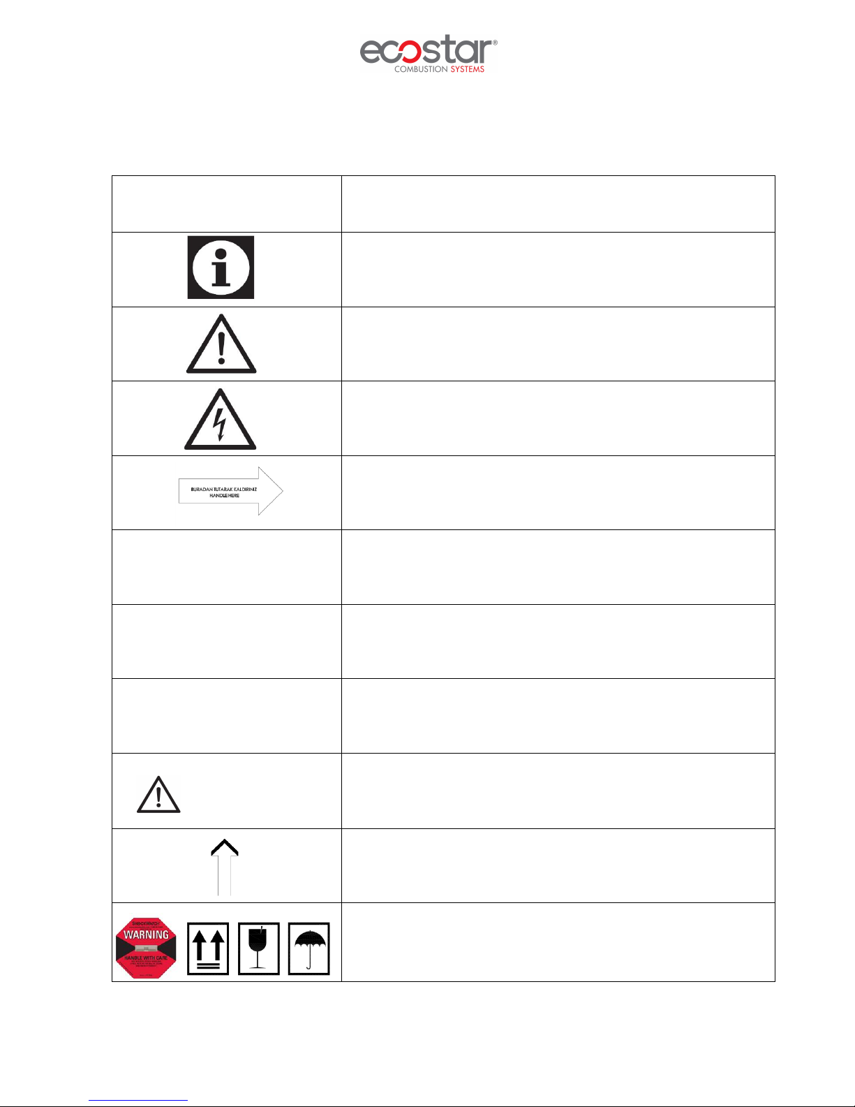
Symbols Symbol Descriptions
Important information and useful hints.
Warning of danger to life or property.
Warning of electrical voltage.
Product handling information.
PF Impulse connection detecting combustion chamber pressure
P
L
P
BR
Impulse connection detecting combustion air pressure
Impulse connection detecting burner gas head
CLEAN THE GAS BURNER.
CLEAN GAS LINE.
ЧИСТАЯ ЛИНИЯ ГАЗ.
13.06.2017 Rev. 01 3
"Clean the gas line" warning on gas line.
Electric motor direction of rotation
Carry in an upright position. Fragile Item. Protect against water.
Page 5

General Safety Rules
• All personnel engaged in installation, disassembly, commissioning, operation, control,
maintenance and repair should have received the necessary training and fully read and understood
this manual.
• No changes that might damage the safety of the burner unit must be made by persons and/or
organizations on the burner unit.
• All operation, commissioning and installation works (except for burning adjustment) should be
carried out when the burner is not operating and after disconnecting the power supply.
Noncompliance with these rules may lead to serious bodily injuries and even death by electrical
shocks or uncontrolled flame formation.
• Repairs concerned with safety elements should be carried out only by the manufacturing company.
• The device should never be used by children, mentally handicapped and inexperienced persons.
• Children must not be allowed to play with the device.
• Keep the device away from explosive and flammable materials.
• Device must intake air, and ventilation and air discharge holes must not be closed.
If you sense gas leakage;
• Shut down valves of all gas devices.
• Open all doors and windows.
• Do not turn on electric devices or do not turn them off if they are working.
• Do not use burner derived tools such as match and lighter.
• Inform the gas company.
Do not store any inflammable materials in boiler room.
Wear hearing protectors if there is noise in boiler room.
In case of fıre or other emergency;
● Switch off the main switch
● Close the main fuel shut-off valve outside the plant.
● Take appropriate actions
13.06.2017 Rev. 01 4
Page 6

The burner installation must be carried out in accordance with the instructions. Vibration can
damage the burner and its components.
Keep boiler doors closed while starting burner and during burner operation.
Check combustion values to be correct by using flue gas analyzer at the whole adjustment range
between minimum, full load, and ignition load.
Use lifting device or belt for lifting fan motor, if necessary.
During the first commissioning of the burner or in case of any revision carried out in the electrical
system or motor cables by any reason, direction of the fan rotation must certainly be checked by
the authorized technical service.
13.06.2017 Rev. 01 5
Page 7

TERMS OF WARRANTY
Main and auxiliary equipment and all components used in Ecostar gas burners are guaranteed for 1
year by TERMO ISI SİST. A.Ş starting from the date of commissioning under the maintenance,
adjustment, operating conditions and relevant mechanic, chemical and thermal effects explained herein.
Please note that this warranty is only valid if the device(s) is commissioned and maintained by our
authorized services.
Our company reserves the right to make any modifications on the product and all instructions
thereof for improvement purposes.
Out of Warranty Conditions
• Any damage arising out of or in relation to customers’ non-compliance to their responsibilities
with regards to installation, commissioning, operation and maintenance,
• Any damage arising out of or in relation to commissioning, repairs and maintenance carried out by
unauthorized services,
• Any damage that may occur during transportation or storage of the product,
• Not preserving the product in its original packaging until the installation stage,
• Incorrect and poor electrical connections, Failures due to incorrect voltage applications, frequent
repetition of voltage fluctuations,
• Any damage that may occur as a result of incorrect fuel usage or, foreign substances in the fuel
used or using of the product without any fuel,
• Any damage that may occur due to foreign particles entered into the product during installation
and operation,
• Failures due to incorrect device selection,
• Any damage to unit due to natural disasters,
• Devices without any warranty certificates,
• Warranty Certificates without the stamp and signature of the authorized dealer or service,
• Devices with any falsification on the warranty certificate or without an original serial number.
• The risks during transportation of device under the responsibility of customer belong to the
customer.
• Presence of misuse faults are indicated in the reports issued by authorized service stations or our
authorized agent, dealer, representative or our factory in case of unavailability of authorized
service stations.
• Customers may apply consumer protection arbitrator committee with regards to this report and
request for an expert report.
13.06.2017 Rev. 01 6
Page 8
BURNER’S GENERAL FEATURES
ECOSTAR gas burners are manufactured such that they operate in gas pressure of min. 20 mbar
and max. 300mbar. at 15%...+10% of nominal voltage, between the ambient temperature range of
-15ºC….+60˚C and declared capacity and boiler pressure ranges with Natural Gas and Liquid Petrol Gas.
Purpose of Use and Work Limits of Burners
• This product works at any load value equivalent to its max. capacity or covered by its capacity
range;
- In hot water and steam boilers,
- In direct and indirect hot air generators,
- Industrial appliances operating at temperature below 600 0C,
- -15 0C…+60 0C ambient temperature range,
- 1N 230 VAC/3N 380VAC /50 Hz feed voltage (-%15…+%10) values,
- Max. 95% relative humidity,
- In well-ventilated open and closed spaces compatible with protection class IP 40.
- Operation with Natural gas and LPG.
This device must never be operated with open flame!
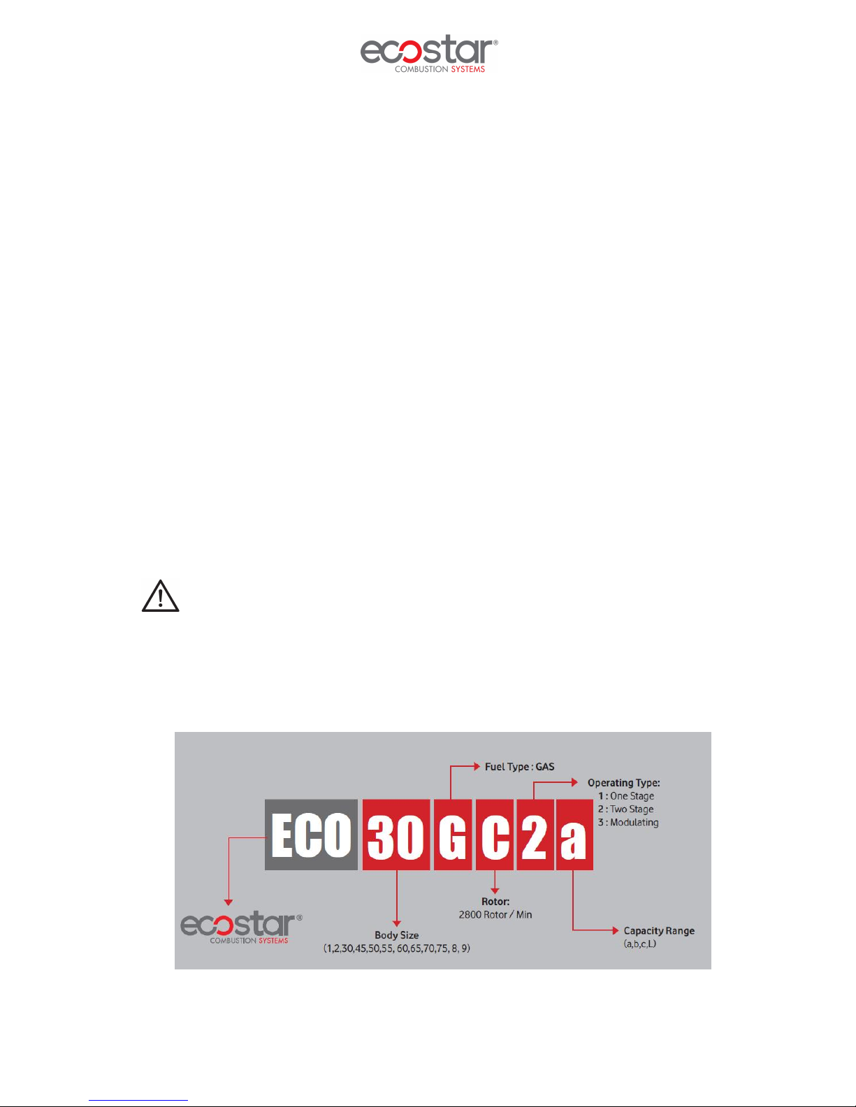
Code Key
13.06.2017 Rev. 01 7
Page 9

Min.
Max.
TECHNICAL DATA
Capacity Table
NEW GENARATION MODULATING GAS BURNERS CAPACITY TABLE
BURNER TYPE CAPACITY CAPACITY
ECO 50 G C 3 NG
ECO 55 G C 3 NG
ECO 55 G C 3a NG
ECO 60 G C 3 NG
ECO 65 G C 3 NG
ECO 70 G C 3 NG
Min.
kcal/h
215.000 1.290.000 250 1.500 26,1 156,4 9,6 57,3 2,20 3N 380
258.000 1.720.000 300 2.000 31,3 208,5 11,5 76,4 3,00 3N 380
258.000 2.150.000 300 2.500 31,3 260,6 11,5 95,6 3,00 3N 380
369.800 2.580.000 430 3.000 44,8 312,7 16,4 114,7 4 3N 380
430.000 3.010.000 500 3.500 52,1 364,8 19,1 133,8 5,5 3N 380
498.800 3.500.200 580 4.070 60,5 424,3 22,2 155,6 7,5 3N 380
Max.
kcal/h
kW
Hu Natural Gas =8250 kcal/Nm
3
Hu LPG=22500 kcal/Nm3
kW
NATURAL GAS
CONSUMPTION
Min.
Nm³/h
Nm³/h
Max.
LPG
CONSUMPTION
Min.
Nm³/h
Max.
Nm³/h
FAN MOTOR
POWER
kW VAC
MAIN
SUPPLY
13.06.2017 Rev. 01 8
Page 10
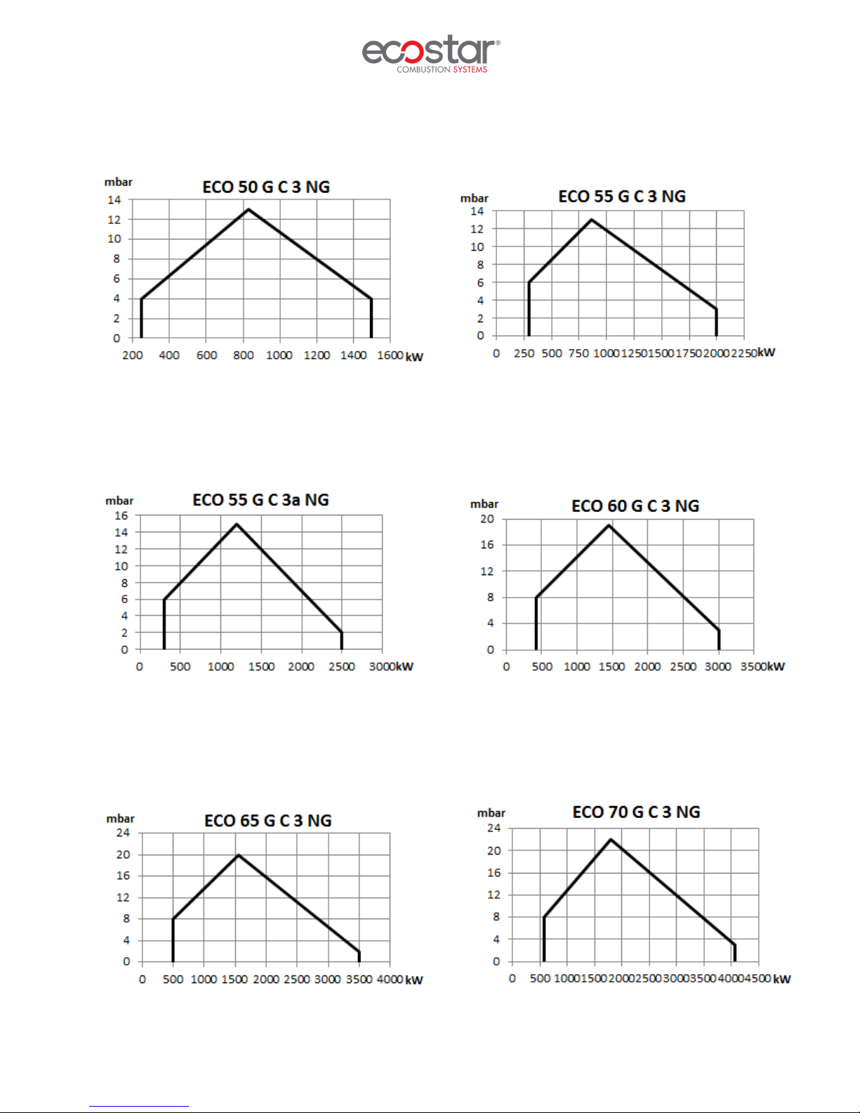
Back Pressure-Capacity Diagrams
13.06.2017 Rev. 01 9
Page 11
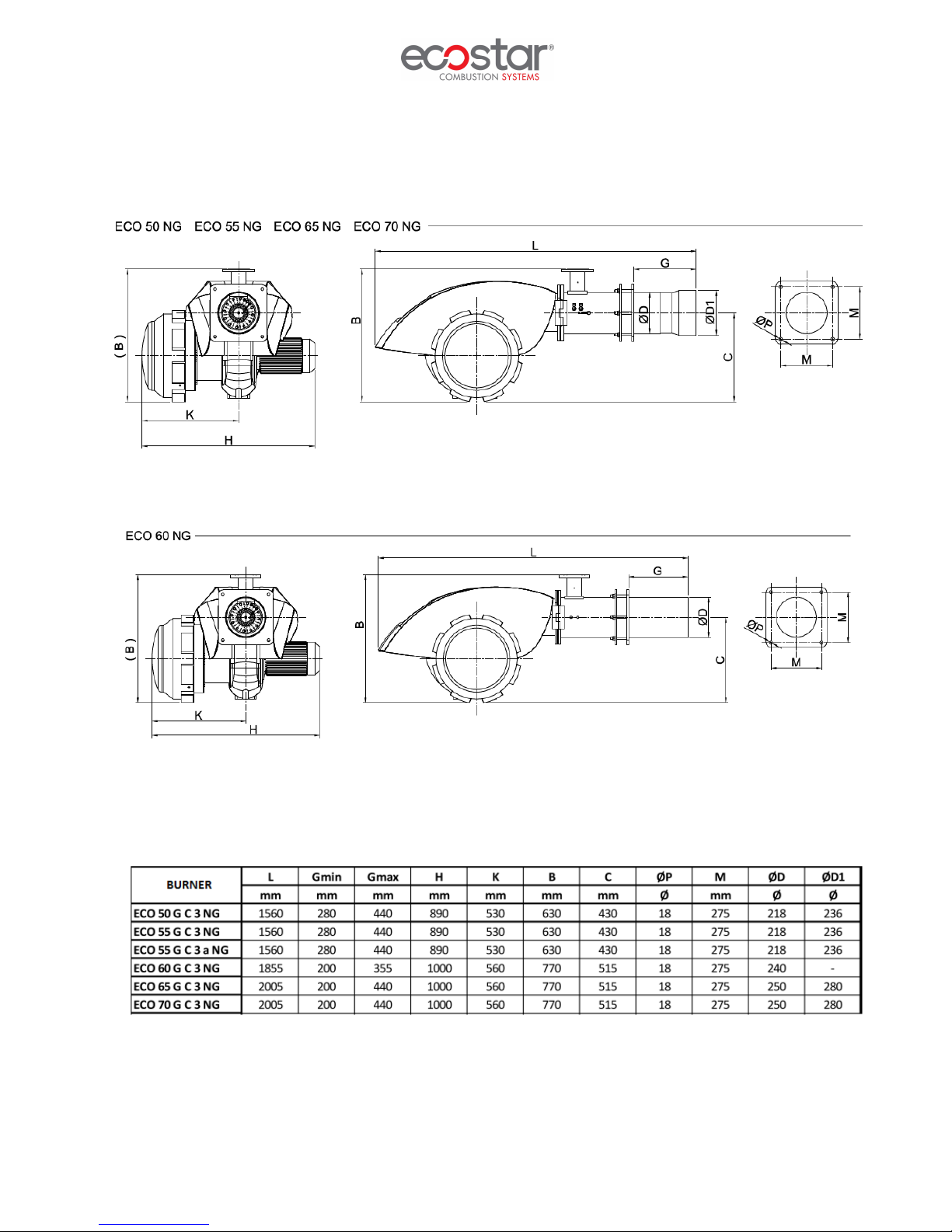
Burner Dimensions
13.06.2017 Rev. 01 10
Page 12
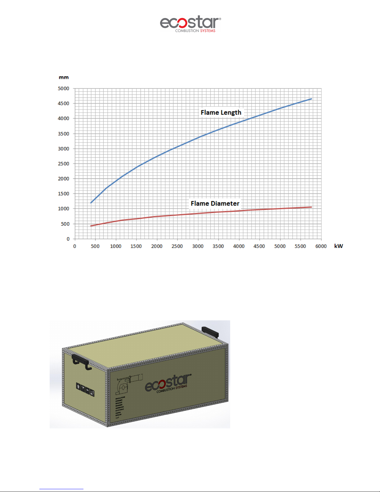
Flame Length and Diameter
Noise Level
Product operates within the range of 75 decibels max. and 85 decibels.
BURNER HANDLING INFORMATION
• Lift the product by holding the handles as seen in the picture.
• Prevent strong impacts on top of the product and vibration while handling the product.
• Do not leave the product in wet environment.
13.06.2017 Rev. 01 11
Page 13
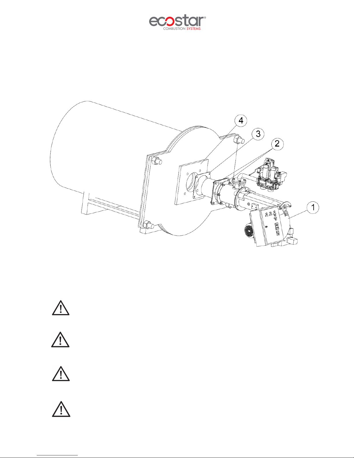
INSTALLATION
Burner Installation Picture
1- Burner
2- Boiler Connection Flange
3- Gasket
4- Boiler Flange
You must definitely ensure sealing between boiler and burner!
Device must be shipped in original packaging!
Do not lift the device holding from servomotor, gas valve, impulse pipes or pressure switch
during installation!
Clean the inside of fuel line thoroughly before installing the burner to the fuel line. Any
damage that may occur due to solid objects and metal particles from the fuel line shall not be
covered by our company.
13.06.2017 Rev. 01 12
Page 14
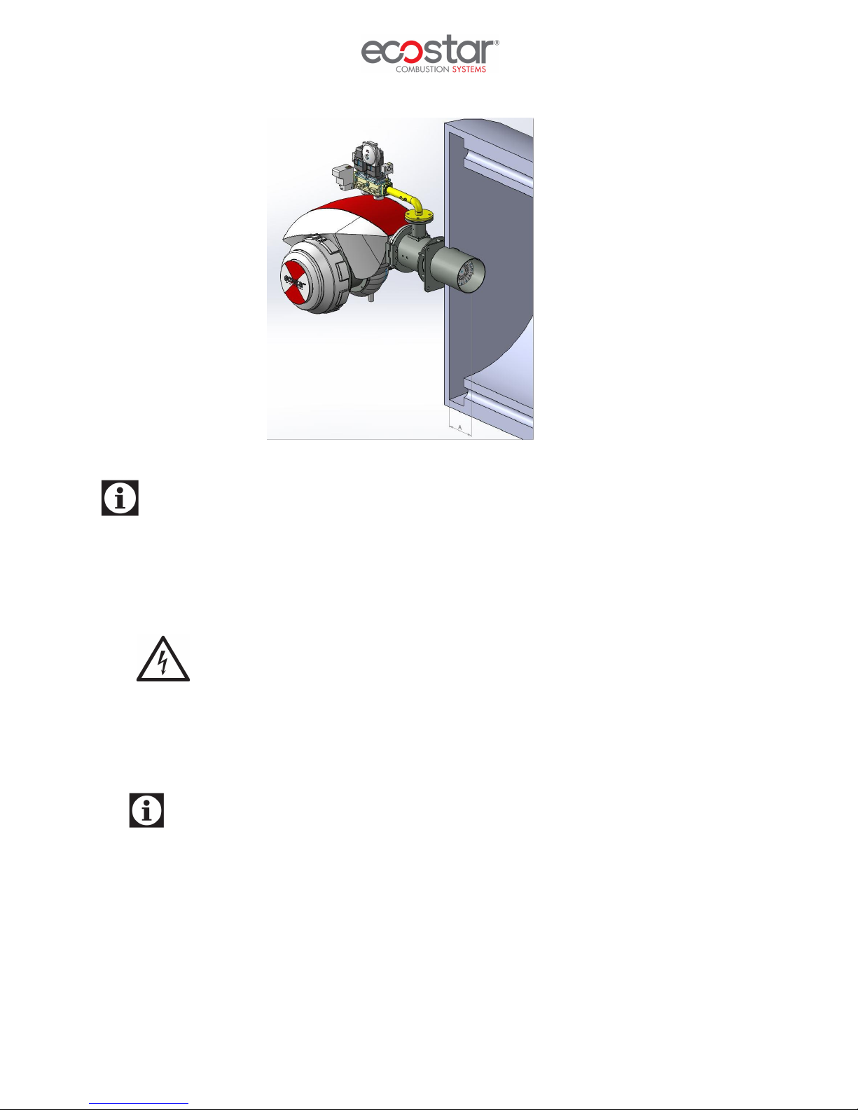
While installing the burner in reverse flame front mirror boilers, flame tube tip must be adjusted
such that it gets inside by 50 mm-100 mm from flue pipes (50mm≤A≤100mm). Otherwise flue gas
temperature will rise and fuel consumption will increase.
COMMISSIONING
Before Commissioning
Electrical connection
Perform electrical connections according to the diagram provided with the burner. Follow general
security rules during installation of electric wiring and making connections. Connect the earthing terminal
in electric panel to the earthing installation.
General Controls
Make sure to perform the following controls before commissioning the burner.
Ø Are the electrical connections correct?
Ø Is there electricity current?
Ø Is there gas?
Ø Has the heating system been filled with water?
Ø Is the thermostat set at the required temperature?
Ø Has the boiler explosion lid been controlled?
Ø Is there sufficient air in boiler room (ventilation section cm² = boiler capacity kW x 7)
Ø Has the boiler been installed correctly? Has the boiler cover been closed properly?
Ø Has the air of the gas line been removed? Has a sealing test been made?
13.06.2017 Rev. 01 13
Page 15
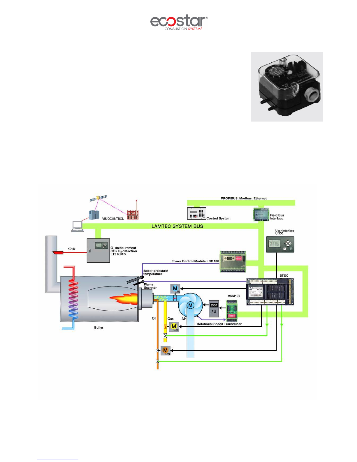
Operation of a modulating burner
Ø Open the main gas valve; check max 300 mbar gas pressure from the manometer.
Ø Open operating switch on the burner panel.
Ø Switch on the modulating control switch.
Ø Switch automatic-hand switch to automatic.
Ø Check the temperature and pressure set values from the modulating control unit.
Ø Ignition will take place at the end of pre-purge process.
Ø 3 sec. later, the gas valve will be opened and combustion will occur.
Ø Flame control system (ionization) will start flame control.
Ø In modulating burner, the burner goes into max. capacity according to the signal from the
modulating control unit.
Ø When the boiler water temperature or steam pressure increase, the modulating control unit will
cause burner to run with min. capacity.
Ø If the boiler water temperature or steam pressure increases despite the operation of burner with
min. capacity, the modulating control unit will stop the burner.
Combustion Adjustment
Gas Adjustment
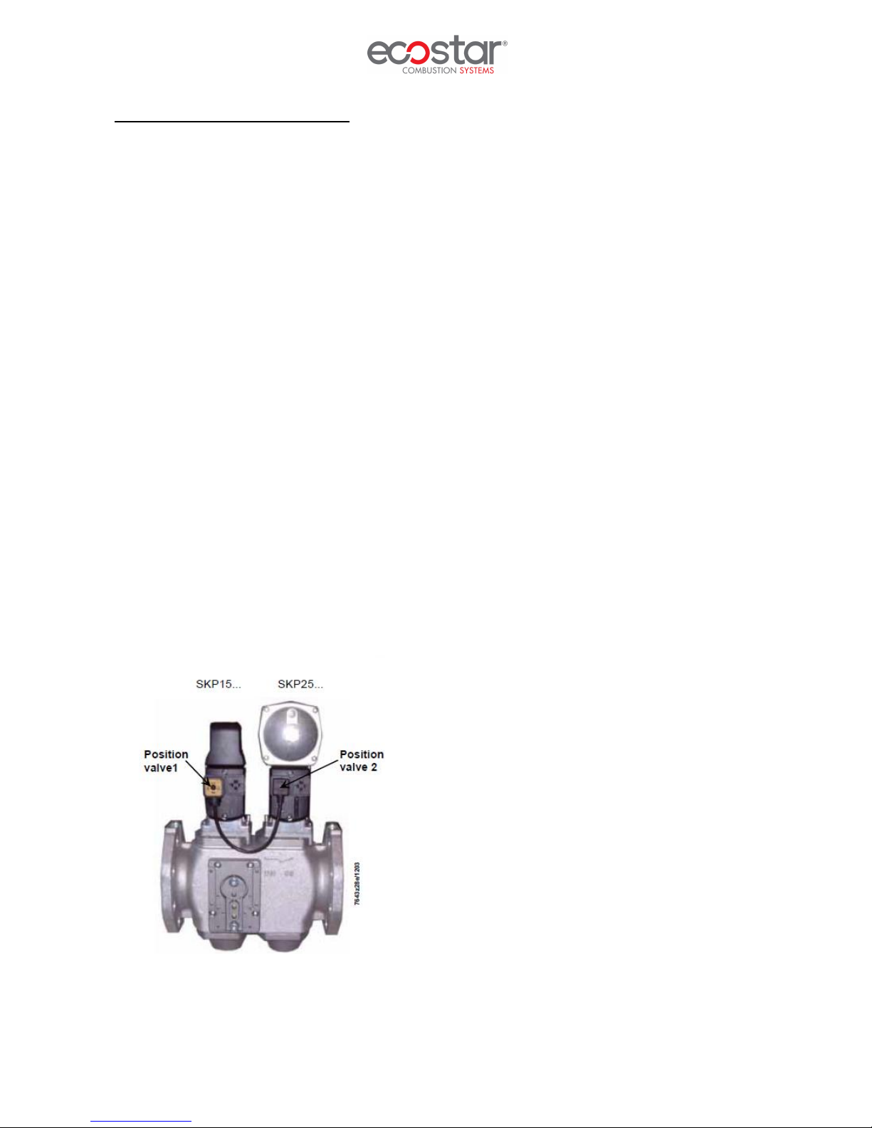
Follow the instructions of the valve manufacturer during installation, dismantling and adjustment of the
gas valve
VGD 40… Series Gas Valve
13.06.2017 Rev. 01 14
Page 16
Air pressure switch adjustment
While the burner is working without any problem, the air pressure switch
is adjusted to desired minimum pressure as follows.
Ø Unscrew the screw of the transparent cover and remove the cover.
Ø Turn the adjustment wheel in the direction to increase the pressure,
note the pressure value at which the burner is failed.
Ø Set the pressure switch to a value 1 mbar lower than the pressure
value at which the burner failed and close the pressure switch lid.
Ø It is recommended that this adjustment is carried out when the
burner is at minimum load.
BT 300
13.06.2017 Rev. 01 15
Page 17
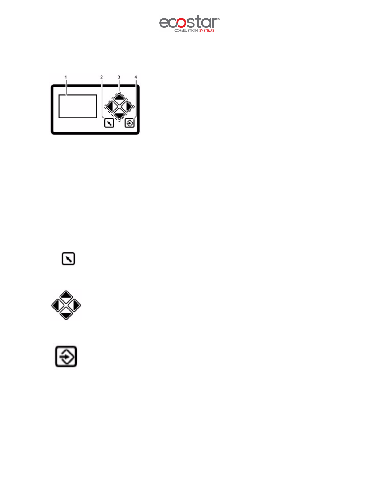
Operating Control and Displays
1 Display
2 Back key
3 Cursor keys
4 Enter key
Display: The display shows in pictograms:
1 - The menu structure
2 - Operating status
3 - Parameters
4 - Error messages
Back key: Jump to previous window.
Cursor keys: You navigate in the menu using the cursor keys. You use the "left'' and
''right'' keys to move step by step to the selected row. At the end of the selected row, the
cursor jumps to the next row down, if possible If the menu has multiple rows, you can use
the "up" and "down" keys to switch rows To display the parameters, switch between the
individual fields.
Enter key: Press ENTER to call up the menu on the start screen. You open the selected
submenu from a menu window. By pressing the ENTER key, you transfer the setting values
from a parameter window.
13.06.2017 Rev. 01 16
Page 18
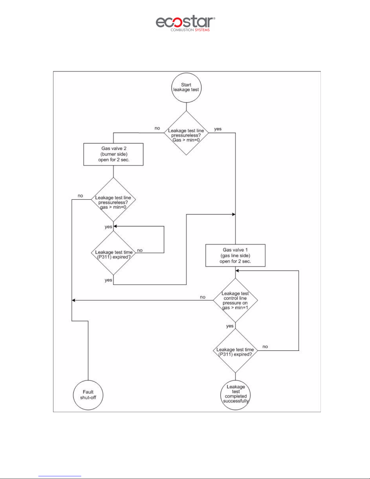
Leakage Test for Main Gas Valves
13.06.2017 Rev. 01 17
Page 19
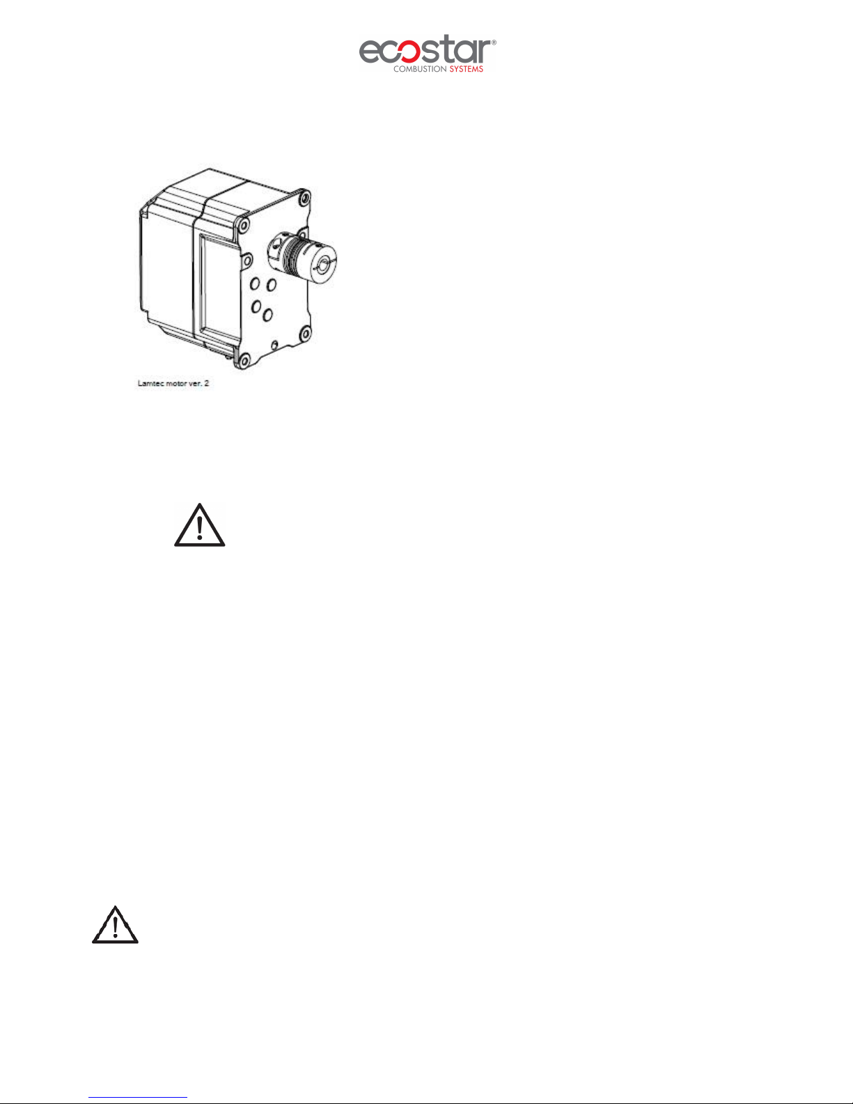
Servomotors
Servomotors drive air dampers, gas butterfly valve and oil regulator. With the help of servomotors
electronic air and fuel ratio control is carried out, controlled by burner control.
Ø Static electricity can damage servomotor.
Ø Do not open servomotor. Do not interfere with or modify unit or equipment connected to it. It may
damage servomotor or change burner settings.
Ø Completely isolate equipment from the main supply before performing any wiring changes in
servomotor connection area.
Ø Check that wiring is in an orderly state.
Ø Protect equipment from condensation, water and ice.
Ø Fall or shock can adversely affect safety functions. Such servomotors may not be put into
operation.
Do not open servomotor. Do not interfere with. It may damage servomotor or change burner
settings.
13.06.2017 Rev. 01 18
Page 20

Function Controls and Adjustments
The BT300 combines the benefits of an electronic fuel-air ratio control system with up to three
motorized actuating devices and an optional module like an analogue output for speed control of the
combustion air fan with an electronic burner control unit. The leakage test, flame monitoring system,
power control unit and (optional) CO/O2 controller for control and optimization of an oil or gas-fired
forced-draught burner are all integrated. The BT300 is suitable for virtually all combustion plants. Safety
interlock chains, monitors (e.g. gas and air pressure) and sensors are wired directly to the BT300. This
greatly reduces the cost of additional relays and wiring. The BT300 was designed to be attached to the
burner. The short wiring paths also save money. As a result, the BT300 is particularly suitable as standard
equipment for monoblock burners. The compact design of the BT300 burner control system also has its
advantages during commissioning. Standardizing the wiring and the unified operator interface minimizes
sources of errors from the start, while intelligent information in the display makes searching for errors
much easier.
Magnetic valves must not be energized during pre-purge. Check if valves are in closed
position!
Final Checks
Ø Switch of all purges after completion of all necessary measurements.
Ø Start and stop the burner at least 3 times to check the operation of the program.
Ø Make sure that all safety circuits on the burner and boiler operate properly before leaving the
installation site.
13.06.2017 Rev. 01 19
Page 21
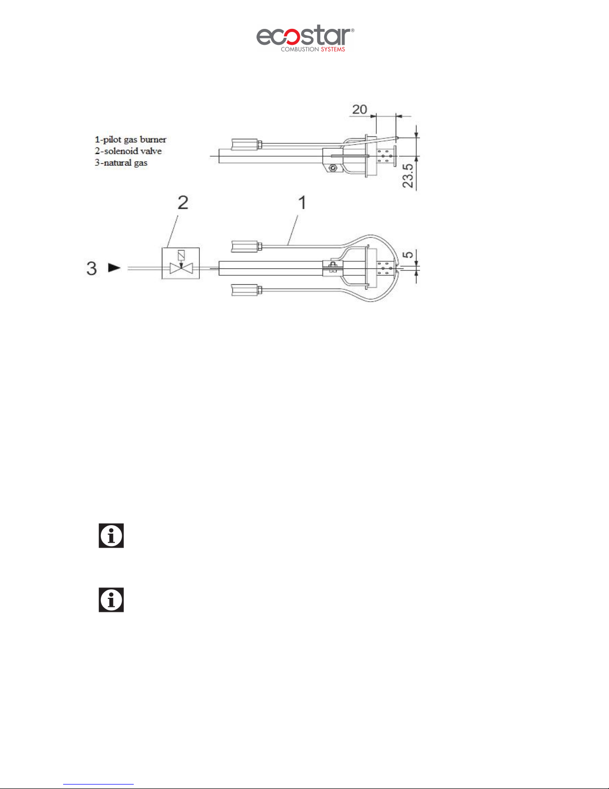
Pilot Ignition System
Pilot gas burner inlet pressure Pmax= 200 mbar
Emission Measurement
In emission measurements, the following values are accepted as reference according to TS EN 676 +A2
standard.
Ø CO < 100 mg/ kWh
Ø %3 ≤ O2 ≤ %5
Ø NOx < 170 mg/ kWh
Ø Excess air ratio 1,2≤ λ ≤ 1,3
It is important for the boiler to be sealed in order to avoid incorrect measurements during
emission measurements.
Boiler water temperature must be between 40 C˚ and 80 C˚ while making emission
measurement in hot water boilers.
13.06.2017 Rev. 01 20
Page 22
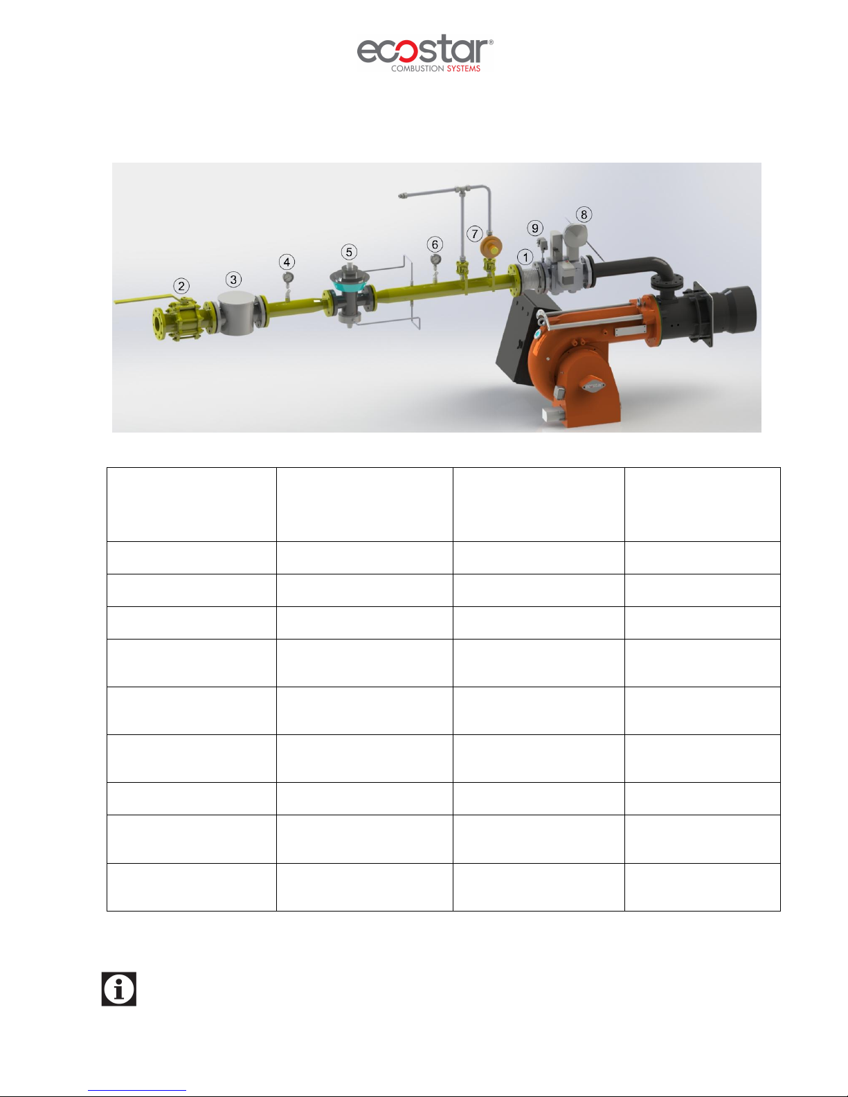
Gas Pass Equipment Required in Gas Line
Pe < 300 mbar
Q<1200kW
1- Compensator 1- Compensator 1- Compensator 1- Compensator
2- Ball valve 2- Ball valve 2- Ball valve 2- Ball valve
3- Gas filter 3- Gas filter 3- Gas filter 3- Gas filter
4- Inlet manometer + valve 4- Inlet manometer + valve 4- Inlet manometer + valve 4- Inlet manometer +
8– Multi-block (safety and
operation solenoids)
9- Sealing Control Set 6- Outlet manometer + valve 9- Sealing Control Set 6- Outlet manometer +
7- Safety discharge valve 7- Safety discharge valve
8– Multi-block (safety and
9- Sealing Control Set 9- Sealing Control Set
Pe > 300 mbar
Q<1200kW
5- Regulator 8– Multi-block (safety and
operation solenoids)
Pe < 300 mbar
Q>1200kW
operation solenoids))
8– Multi-block (safety
Pe > 300 mbar
Q>1200kW
valve
5- Regulator
valve
and operation solenoids)
Threaded and flanged connections may vary depending on the gas pressure and consumption.
13.06.2017 Rev. 01 21
Page 23

MAINTENANCE
Monthly Maintenance
Monthly maintenance is a comprehensive process where general checks of burner and peripheral
components are performed to prevent possible faults. After completion of maintenance and adjustment
processes, make sure to perform an emission analysis.
Ø Clean the filters on the main line and multiblock.
Ø Check the burner gas tip.
Ø Perform insulation measurements of ignition and ionization electrodes; replace electrodes should
there be leakage to the body.
Ø Check ignition cables and sockets.
Ø Check all wiring points. Tighten loose connections.
Ø Clean the dust and layers accumulated on the fan and air damper.
Ø Check gas line pressure, it must be the same with the first adjusted pressure, otherwise burner load
and emission values will also have changed.
Ø Check all bolts of the burner. Tighten loose bolts.
Ø After starting the burner and adjusting air damper, perform flue gas emission measurement and
check if there is an ideal combustion.
Seasonal Maintenance
Comprehensive maintenance work when the burner is restarted after long periods of shut-down or
interruptions. After completion of maintenance and adjustment processes, make sure to perform a
combustion analysis.
Ø Check insulation resistance of electric motor.
Ø Replace ignition and ionization electrodes with new ones.
Ø Clean air fan and clamps.
Ø Check the operating function.
Ø Check boiler thermostats.
Ø Check cleanliness of boiler inside and clean if necessary.
Follow installation directions during maintenance.
13.06.2017 Rev. 01 22
Page 24

PERIODICAL FLUE GAS MEASUREMENT REPORT
Fuel
Consumption
(m³/h)
CO
(ppm)
O
2
(%)
CO
2
(ppm)
NO
X
(ppm)
Yield
(%)
Flue
Temp.
Date
(ºC)
Signature
13.06.2017 Rev. 01 23
Page 25

AFTER-SALES SERVICES
Dear Customer,
We believe that providing a good service is as important as providing a good product. Therefore, we
continue offering wide range of comprehensive services to our conscious customers.
Our contact details for your requests and complaints
Esentepe Mah.Milangaz Cad. No:75 K:3
Kartal Monumento Plaza
KARTAL/İSTANBUL/TÜRKİYE
Tel: +90 216 442 93 00
Fax: +90 216 370 45 03
Factory Contact Details
Türkgücü OSB
Bülent Ecevit Bulvarı No:11
ÇORLU/TEKİRDAĞ/TÜRKİYE
Tel: +90 282 685 44 80-81
Fax: +90 282 685 42 09
Also you can contact with us:
Web site : www.ecostar.com.tr
E - mail : [email protected]
Please observe the following recommendations.
• Use the product in accordance with the principles of this manual.
• For any service demands regarding the product, please contact our Service Center from the
abovementioned phone numbers.
• Upon your purchase, register your warranty certificate during installation.
13.06.2017 Rev. 01 24
Page 26

NOTES
Please record and forward your measurements and observations to us
www.ecostar.com.tr
13.06.2017 Rev. 01 25
 Loading...